WO2017217037A1 - ワイパーブレード及びその製造方法 - Google Patents
ワイパーブレード及びその製造方法 Download PDFInfo
- Publication number
- WO2017217037A1 WO2017217037A1 PCT/JP2017/009207 JP2017009207W WO2017217037A1 WO 2017217037 A1 WO2017217037 A1 WO 2017217037A1 JP 2017009207 W JP2017009207 W JP 2017009207W WO 2017217037 A1 WO2017217037 A1 WO 2017217037A1
- Authority
- WO
- WIPO (PCT)
- Prior art keywords
- leaf spring
- wiper blade
- blade
- leaf
- blade body
- Prior art date
- Legal status (The legal status is an assumption and is not a legal conclusion. Google has not performed a legal analysis and makes no representation as to the accuracy of the status listed.)
- Ceased
Links
Images

Classifications
-
- B—PERFORMING OPERATIONS; TRANSPORTING
- B60—VEHICLES IN GENERAL
- B60S—SERVICING, CLEANING, REPAIRING, SUPPORTING, LIFTING, OR MANOEUVRING OF VEHICLES, NOT OTHERWISE PROVIDED FOR
- B60S1/00—Cleaning of vehicles
- B60S1/02—Cleaning windscreens, windows or optical devices
- B60S1/04—Wipers or the like, e.g. scrapers
- B60S1/32—Wipers or the like, e.g. scrapers characterised by constructional features of wiper blade arms or blades
- B60S1/38—Wiper blades
Definitions
- the present invention relates to a wiper blade used for a wiper for wiping automobile window glass and the like, and a method for manufacturing the wiper blade.
- an aero type wiper blade made of a combination of a bow-shaped leaf spring and rubber (elastomer) is used without a link portion as in Patent Document 1.
- the above aero-type wiper blades can be compactly designed, have less wind noise, and have no link part, so the link part will not freeze and move.
- the present invention has been made in view of the above points, and an object of the present invention is to make it compact, free from wind noise, and easy to ensure strength.
- the entire circumference of the leaf spring is covered with the blade body.
- a leaf spring extending in the longitudinal direction; A blade body covering the entire circumference including both longitudinal ends of the leaf spring; And a tongue that is integrally formed with the blade body and extends in the longitudinal direction to contact the window glass.
- the blade body covers the entire circumference including both ends in the longitudinal direction of the leaf spring that generates the down force so as not to be lifted during high speed operation, so the appearance is good and the durability is high. Since the tongue portion and the blade body are integrally formed, the number of parts is reduced, and there is no boundary and there is little wind noise. Moreover, since there is no link part like a general tournament structure, it can prevent that a link part freezes and a wiper does not move.
- the blade body and the tongue are made of the same rubber or elastomer.
- the leaf spring can be insert-molded by vulcanization if it is rubber, and the leaf spring is easily insert-molded by heating if it is a thermoplastic elastomer.
- the plate spring is composed of two plate members and is provided side by side in the width direction of the blade body.
- the strength is increased by providing two leaf springs, and it is easy to prevent the wiper blade from being damaged even when snow is frozen on the window glass.
- Both ends in the longitudinal direction of the leaf spring are integrally covered with the same material constituting the blade body.
- the number of parts is reduced as compared with the case where both ends in the longitudinal direction are covered with a cap or the like different from the blade body, the assembly is easy, there is no boundary, the wind noise is small, and the compact.
- the manufacturing method of the wiper blade of the fifth invention is configured such that the blade body is molded so that the entire circumference including both longitudinal ends of the leaf spring extending in the longitudinal direction is embedded.
- the intermediate molded body is extruded so as to have leaf spring insertion openings for inserting the leaf springs on both sides in the width direction, After inserting the leaf springs from the leaf spring insertion ports, Each of the leaf spring insertion ports is closed with the rubber during vulcanization.
- plate spring can be each inserted from a corresponding leaf
- the blade body is formed so that the entire circumference including the both ends in the longitudinal direction of the leaf spring extending in the longitudinal direction is embedded, so that it is compact and has no wind noise. The strength can be easily secured. Further, since the entire circumference of the leaf spring is embedded in the blade body, the glass to be wiped is not damaged.
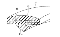
- FIG. 2 is a perspective view showing a wiper blade broken along line II-II in FIG. 1.
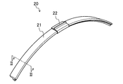
- FIG. 1 shows a wiper blade 20 according to an embodiment of the present invention.
- this wiper blade 20 is attached to a wiper arm (not shown) provided on a windshield of an automobile as a window glass to wipe off the windshield. is there.
- the wiper blade 20 includes a pair of leaf springs 15 extending in the longitudinal direction, and a blade body 21 that covers the entire circumference of the pair of leaf springs 15.
- the leaf spring 15 is composed of two plate members, and is provided side by side in the width direction of the blade body 21.
- the blade body 21 is integrally formed with a tongue 21a that extends in the longitudinal direction and contacts the windshield.
- the blade body 21 and the tongue 21a are made of the same rubber material 9.
- both end portions in the longitudinal direction of the leaf spring are also covered with the same rubber material 9 constituting the blade body 21.
- the blade body 21 covers the entire circumference including both longitudinal ends of the leaf spring 15 formed in an arc shape so as to generate a down force that prevents the surface from being lifted during high-speed operation.
- the nature is also high. Since the tongue portion 21a and the blade main body 21 are integrally formed, the number of parts is reduced, and there is no boundary and there is little wind noise, and the device becomes compact. Moreover, since there is no link part like a general tournament structure, it can prevent that a link part freezes and a wiper does not move. Further, since the entire circumference of the leaf spring 15 is embedded in the blade body 21, the glass to be wiped is not damaged.
- a wiper arm coupling adapter 22 is provided at the longitudinal center of the blade body 21.
- the shape, material, and the like of the wiper arm connection adapter 22 are not particularly limited.
- the blade body 21 is formed so that the leaf spring 15 extending in the longitudinal direction is embedded. As a result, the leaf spring 15 is completely embedded in the blade body 21, so that the appearance is good and the quality is stable.
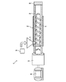
- an unmolded rubber material 9 is extruded by an extruder 1 to form an intermediate molded body 21 ′ that becomes a blade body 21.
- the extruder 1 includes an extruder main body 2, and the extruder main body 2 has a cylindrical cylinder 3.
- a screw 4 is rotated by a motor 6 via a gear 5.
- a die 8 is provided at the tip of the cylinder 3.
- the die 8 is provided with an opening 8a corresponding to the shape of the intermediate molded body 21 '.
- FIG. 3 As shown in FIG. 3, an unmolded rubber material 9 is extruded by an extruder 1 to form an intermediate molded body 21 ′ that becomes a blade body 21.
- the extruder 1 includes an extruder main body 2, and the extruder main body 2 has a cylindrical cylinder 3.
- a screw 4 is rotated by a motor 6 via a gear 5.
- a die 8 is provided at the tip of the cylinder 3.
- the die 8 is provided with an opening 8a corresponding to the shape of
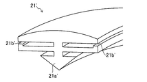
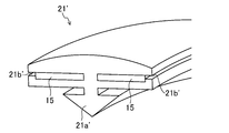
- the intermediate molded body 21 ′ is pushed out so that the tongue portion 21 a ′ is disposed at the center in the width direction and the leaf spring insertion openings 21 b ′ into which the leaf springs 15 are inserted on both sides in the width direction. It is.
- the cylinder 3 is configured such that a rubber material 9 can be input from a hopper 7.
- the rubber material 9 is made of, for example, natural rubber, silicone rubber, graphite rubber or the like, but the material is not particularly limited, but urethane rubber is advantageous because it can take a wide variety of colors.
- blending rubber materials 5 parts of zinc oxide, 1 part of stearic acid, 4.5 part of anti-aging agent, 35 part of HAF carbon black, 5 part of naphthenic oil, 1 part of sulfur are added to 100 parts by weight of natural rubber. Each 2.5 parts by weight of a sulfur accelerator is blended.
- the blending amount is not particularly limited, and the antiaging agent and the vulcanization accelerator are not particularly limited, and may be appropriately adjusted.
- the extruder may be a general-purpose extruder with a gear pump.
- the screw rotation speed is 20 rpm
- the cylinder set temperature is 60 ° C.
- the screw set temperature is 60 ° C.
- the head set temperature is 70 ° C.
- the die set temperature is 80 ° C.
- these temperatures are not limited to this.
- the extrusion molding is performed in this way, it is possible to mold an intermediate molded body 21 ′ having a stable cross-sectional shape of the blade body 21. Further, compared with molding using a mold, the mold cost is not required, which is advantageous in terms of cost.
- a metal coil material 11 having appropriate rigidity and elasticity such as spring steel is prepared.
- heat treatment is performed in the furnace 13 to create a leaf spring coil 14.
- the heat treatment conditions are not particularly limited, and may be determined from the material of the coil material 11, the plate thickness, the width, the cross-sectional shape, the necessary spring constant, and the like.
- the leaf spring coil 15 is cut by a predetermined length to prepare a leaf spring member 15 '.
- a plate spring 15 is formed by forming a through hole 15a at the center in the longitudinal direction of the plate spring member 15 'by drilling.
- the leaf spring 15 is formed into an arc shape so as to generate a down force that prevents the leaf spring 15 from floating during high-speed operation.
- the leaf spring 15 is inserted into the intermediate molded body 21 ′.
- the plate springs 15 are respectively inserted from the plate spring insertion openings 21 b ′ provided on both sides in the width direction of the intermediate molded body 21 ′. Since the leaf springs 15 can be respectively inserted from the corresponding leaf spring insertion openings 21b ', the leaf springs 15 are surely arranged at fixed positions, and thereafter, the intermediate molded body 21' is bridged so that both longitudinal ends of the leaf springs 15 are connected. The entire circumference can be reliably covered.
- the intermediate molded body 21 ′ into which the leaf spring 15 is inserted is put into a vulcanizer (not shown), the rubber material 9 is cross-linked, and each leaf spring insertion port 21 b ′ is closed.
- a vulcanizer not shown
- the primary vulcanization may be performed at 260 ° C. for 2 minutes and the secondary vulcanization may be performed at 200 ° C. for 20 minutes, but this is not particularly limited.
- a blade body 21 made of a single rubber material 9 covers the entire circumference of the leaf spring 15 as shown in a cross section. Since the entire circumference including both longitudinal ends of the leaf spring 15 is covered during vulcanization, it is easy to provide a leaf spring insertion port 21b 'for inserting the leaf spring 15 at the stage of the intermediate molded body 21'. In addition, the number of parts is small compared to a conventional product in which both ends in the longitudinal direction are sealed with separate members, and assembly is extremely easy.
- the blade body 21 is formed so that the entire circumference including the both longitudinal ends of the leaf spring 15 extending in the longitudinal direction is embedded, so that it is compact and wind-cut. There is no sound and the strength can be easily secured. Further, since the entire circumference of the leaf spring 15 is embedded in the blade body 21, the glass to be wiped is not damaged.
- the present invention may be configured as follows with respect to the above embodiment.
- the wiper blade 20 wipes the windshield.
- the wiper blade 20 may be used for a rear glass other than the windshield, or may be used for wiping a window glass other than an automobile.
- the blade body 21 is made of the rubber material 9, but if this rubber material 9, the leaf spring 15 can be insert-molded by vulcanization.
- the blade body 21 may be made of a thermoplastic elastomer. In this case, there is a merit that the leaf spring 15 can be easily insert-molded by heating.
Landscapes
- Engineering & Computer Science (AREA)
- Mechanical Engineering (AREA)
- Extrusion Moulding Of Plastics Or The Like (AREA)
Abstract
長手方向に延びる板バネ(15)の長手方向両端を含む全周が埋設されるようにブレード本体(21)を成形する。例えば、押出機で未架橋状態のゴム材料を押し出してブレード本体(21)となる中間成形体を成形し、中間成形体に板バネ(15)を差し込み、板バネ(15)が差し込まれた中間成形体を加硫して板バネ(15)の長手方向両端を含む全周を覆ってワイパーブレードを製造する。
Description
本発明は、自動車の窓ガラス等を拭き取るワイパーに使用されるワイパーブレード及びその製造方法に関する。
従来より、ワイパーアームに取り付けられるプレス成形品を用いたリンク構造のワイパーブレードは知られている。このトーナメント構造では、風切り音が生じたり、低温地域ではリンク部が凍結して動かなかったりする、という欠点がある。
近年、このトーナメントタイプを改善したデザインワイパーも登場している。
一方、例えば、特許文献1のようなリンク部を有さず、弓形の板バネとゴム(エラストマー)の組み合わせからなるエアロタイプのワイパーブレードが用いられている。
上記エアロタイプのワイパーブレードは、コンパクトな設計が可能で風切り音が少なく、また、リンク部を有さないので、リンク部が凍って動かないということはない。
しかしながら、従来のワイパーブレードでは、ウインドーに接するワイパーリップ部と、支持要素を覆うケースイングとを別の材料で構成しているので、構造が複雑になると共に、製造工程が増える、という問題がある。
本発明は、かかる点に鑑みてなされたものであり、その目的とするところは、コンパクトで、風切り音もなく、強度確保しやすいものにすることにある。
上記の目的を達成するために、この発明では、板バネの全周をブレード本体で覆うようにした。
具体的には、第1の発明では、長手方向に延びる板バネと、
上記板バネの長手方向両端部を含む全周を覆うブレード本体と、
上記ブレード本体に一体に成形され、長手方向に延びて窓ガラスに接する舌部とを備えている。
上記板バネの長手方向両端部を含む全周を覆うブレード本体と、
上記ブレード本体に一体に成形され、長手方向に延びて窓ガラスに接する舌部とを備えている。
上記の構成によると、高速運転時に浮き上がらないようにするダウンフォースを発生させる板バネの長手方向両端部を含む全周をブレード本体で覆っているので、外観がよくて耐久性も高い。舌部とブレード本体とを一体に成形してあるので、部品点数が減ると共に、境目がなく風切り音が少なくてコンパクトなものとなる。また、一般的なトーナメント構造のようにリンク部がないので、リンク部が凍結してワイパーが動かないということを防止できる。
第2の発明では、第1の発明において、
上記ブレード本体と上記舌部とは、同一のゴム又はエラストマーよりなる。
上記ブレード本体と上記舌部とは、同一のゴム又はエラストマーよりなる。
上記の構成によると、ゴムであれば加硫により板バネをインサート成形でき、熱可塑性のエラストマーであれば加熱により板バネをインサート成形しやすい。
第3の発明では、第1又は第2の発明において、
上記板バネは、2本の板部材よりなり、上記ブレード本体の幅方向に並んで設けられている。
上記板バネは、2本の板部材よりなり、上記ブレード本体の幅方向に並んで設けられている。
上記の構成によると、板バネを2本設けることで強度が上がり、窓ガラスに雪が凍り付いたような場合でもワイパーブレードが損傷するのを防止しやすい。
第4の発明では、第1から第3のいずれか1つの発明において、
上記板バネの長手方向両端部は、上記ブレード本体を構成する同一の材料で一体に覆われている。
上記板バネの長手方向両端部は、上記ブレード本体を構成する同一の材料で一体に覆われている。
上記の構成によると、長手方向両端部をブレード本体とは異なるキャップ等で覆うものに比べて部品点数が減り、組立が容易で、しかも境目がなく風切り音が少なくてコンパクトなものとなる。
第5の発明のワイパーブレードの製造方法は、長手方向に延びる板バネの長手方向両端を含む全周が埋設されるようにブレード本体を成形する構成とする。
上記の構成によると、板バネの長手方向両端を含む全周が完全にブレード本体に埋設されるので、見映えがよく、品質も安定し、風切り音も発生しにくい。
第6の発明では、第5の発明において、
押出機で未架橋状態のゴムを押し出して上記ブレード本体となる中間成形体を成形し、
上記中間成形体に上記板バネを差し込み、
上記板バネが差し込まれた上記中間成形体を加硫して該板バネの長手方向両端を含む全周を覆う。
押出機で未架橋状態のゴムを押し出して上記ブレード本体となる中間成形体を成形し、
上記中間成形体に上記板バネを差し込み、
上記板バネが差し込まれた上記中間成形体を加硫して該板バネの長手方向両端を含む全周を覆う。
上記の構成によると、押し出し成形なので、安定したブレード本体の断面形状の中間成形体を成形できる。また、加硫時に板バネの長手方向両端を含む全周を覆うようにしているので、中間成形体の段階では板バネを挿入するための開口等を設けやすい。
第7の発明では、第6の発明において、
上記中間成形体は、幅方向両側に上記板バネを挿入する板バネ挿入口をそれぞれ有するように押し出され、
それぞれの上記板バネ挿入口から上記板バネをそれぞれ挿入した後、
加硫時にそれぞれの上記板バネ挿入口を上記ゴムで閉じる。
上記中間成形体は、幅方向両側に上記板バネを挿入する板バネ挿入口をそれぞれ有するように押し出され、
それぞれの上記板バネ挿入口から上記板バネをそれぞれ挿入した後、
加硫時にそれぞれの上記板バネ挿入口を上記ゴムで閉じる。
上記の構成によると、板バネを対応する板バネ挿入口からそれぞれ挿入できるので、確実に板バネを定位置に配置して、その後、中間成形体を架橋させて板バネの長手方向両端を含む全周を確実に覆うことができる。
以上説明したように、本発明によれば、長手方向に延びる板バネの長手方向両端を含む全周が埋設されるようにブレード本体を成形するようにしたことにより、コンパクトで、風切り音もなく、強度確保しやすいものにすることができる。また、板バネの全周がブレード本体に埋設されているので、拭き取り対象のガラスを傷付けない。
以下、本発明の実施形態を図面に基づいて説明する。
-ワイパーブレードの構成-
図1は本発明の実施形態のワイパーブレード20を示し、例えば、このワイパーブレード20は、図示しない、窓ガラスとしての自動車のフロントガラスに設けられたワイパーアームに取り付けられてフロントガラスを拭き取るものである。
図1は本発明の実施形態のワイパーブレード20を示し、例えば、このワイパーブレード20は、図示しない、窓ガラスとしての自動車のフロントガラスに設けられたワイパーアームに取り付けられてフロントガラスを拭き取るものである。
図2にも示すように、ワイパーブレード20は、長手方向に延びる一対の板バネ15と、これら一対の板バネ15の全周を覆うブレード本体21とを備えている。板バネ15は、2本の板部材よりなり、ブレード本体21の幅方向に並んで設けられている。板バネ15を2本設けることで強度を向上させることができ、窓ガラスに雪が凍り付いたような場合でもワイパーブレードが損傷するのを防止しやすくなっている。
このブレード本体21には、長手方向に延びてフロントガラスに接する舌部21aが一体に成形されている。ブレード本体21と舌部21aとは、同一のゴム材料9よりなる。特に、板バネの長手方向両端部もブレード本体21を構成する同一のゴム材料9で覆われている。
このように、高速運転時に浮き上がらないようにするダウンフォースを発生させるように弓形に成形された板バネ15の長手方向両端を含む全周をブレード本体21で覆っているので、外観がよくて耐久性も高い。舌部21aとブレード本体21とを一体に成形してあるので、部品点数が減ると共に、境目がなく風切り音が少なくてコンパクトなものとなる。また、一般的なトーナメント構造のようにリンク部がないので、リンク部が凍結してワイパーが動かないということを防止できる。また、板バネ15の全周がブレード本体21に埋設されているので、拭き取り対象のガラス等を傷付けない。
なお、ブレード本体21の長手方向中央には、ワイパーアーム連結用アダプタ22が設けられている。このワイパーアーム連結用アダプタ22の形状、材質等は、特に限定されない。
-ワイパーブレードの製造方法-
次に、本実施形態に係るワイパーブレード20の製造方法について説明する。
次に、本実施形態に係るワイパーブレード20の製造方法について説明する。
この製造方法では、長手方向に延びる板バネ15が埋設されるようにブレード本体21を成形する。このことで、板バネ15が完全にブレード本体21に埋設されるため、見映えがよく、品質も安定する。
具体的には、まず、図3に示すように、押出機1で未架橋状態のゴム材料9を押し出してブレード本体21となる中間成形体21’を成形する。押出機1は、押出機本体2を備え、この押出機本体2は、円筒状のシリンダ3を有する。このシリンダ3内に、スクリュー4がギア5を介してモータ6により回転されるようになっている。シリンダ3の先端には、ダイ8が設けられており、図4に示すように、このダイ8には、中間成形体21’の形状に対応した開口8aが設けられている。図5に示すように、中間成形体21’は、幅方向中央に舌部21a’が配置されると共に、幅方向両側に板バネ15を挿入する板バネ挿入口21b’をそれぞれ有するように押し出される。シリンダ3には、ホッパー7からゴム材料9が投入可能に構成されている。ゴム材料9は、例えば、天然ゴム、シリコーンゴム、グラファイトゴム等よりなるが材料は特に限定されないが、ウレタンゴムであれば、豊富なカラーバリエーションをとることができて有利である。
ゴム材料の配合例としては、天然ゴム100重量部に対し、酸化亜鉛を5、ステアリン酸を1、老化防止剤を4.5、HAFカーボンブラックを35、ナフテンオイルを5、硫黄を1、加硫促進剤を2.5重量部それぞれ配合する。この配合量は特に限定されず、老化防止剤や加硫促進剤は特に限定されず、適宜調整すればよい。
押出機は、汎用のギアポンプ付押出機を使用すればよく、例えば、スクリュー回転数20rpm、シリンダ設定温度60℃、スクリュー設定温度60℃、ヘッド設定温度70℃、ダイ設定温度80℃とすればよいが、これらの温度はこれに限定されない。
このように押し出し成形なので、安定したブレード本体21の断面形状の中間成形体21’を成形できる。また、金型を利用した成型に比べると、金型費が不要となるので、コスト面でも有利である。
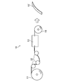
一方、図7に示すように、板バネ製造工程において、バネ鋼等の適度な剛性及び弾性を有する金属のコイル材11を準備する。
次いで、このコイル材11からバネ鋼を引き出しながら、曲げロール12で曲げ加工を行う。
次いで、炉13で熱処理を行って板バネコイル14を作成する。熱処理条件は、特に限定されず、コイル材11の材質、板厚、幅、断面形状、必要なバネ定数等より決定すればよい。
次いで、この板バネコイル14から所定長さ分カットして板バネ部材15’を準備する。
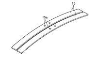
次いで、図8に示すように、孔開け加工で板バネ部材15’の長手方向中央に貫通孔15aを形成して板バネ15を作成する。板バネ15は、高速運転時に浮き上がらないようにするダウンフォースを発生させるように弓形に成形される。
次いで、中間成形体21’に板バネ15を差し込む。具体的には、図6に示すように、中間成形体21’の幅方向両側に設けた板バネ挿入口21b’から板バネ15をそれぞれ挿入する。板バネ15を対応する板バネ挿入口21b’からそれぞれ挿入できるので、確実に板バネ15を定位置に配置して、その後、中間成形体21’を架橋させて板バネ15の長手方向両端を含む全周を確実に覆うことができる。
次いで、板バネ15が差し込まれた中間成形体21’を図示しない加硫機に入れ、ゴム材料9を架橋させ、それぞれの板バネ挿入口21b’を閉じる。加硫機での加熱温度、加熱時間等は、ゴム材料9の特性等により設定すればよい。例えば、一次加硫を260℃で2分行い、二次加硫を200℃で20分行えばよいが、これは特に限定されない。
図2に断面を示すように、単一のゴム材料9よりなるブレード本体21が板バネ15の全周を覆う。加硫時に板バネ15の長手方向両端を含む全周を覆うようにしているので、中間成形体21’の段階では板バネ15を挿入するための板バネ挿入口21b’を設けやすい。また、長手方向両端を別部材で封じるような従来品に比べて部品点数が少なく、組立も極めて容易である。
したがって、本実施形態に係るワイパーブレード20によると、長手方向に延びる板バネ15の長手方向両端を含む全周が埋設されるようにブレード本体21を成形するようにしたことにより、コンパクトで、風切り音もなく、強度確保しやすいものにすることができる。また、板バネ15の全周がブレード本体21内に埋設されているので、拭き取り対象であるガラスを傷付けない。
(その他の実施形態)
本発明は、上記実施形態について、以下のような構成としてもよい。
本発明は、上記実施形態について、以下のような構成としてもよい。
すなわち、上記実施形態では、ワイパーブレード20は、フロントガラスを拭き取るものとしたが、フロントガラス以外のリアガラス等に用いられてもよいし、自動車以外の窓ガラスを拭き取るために用いられてもよい。
上記実施形態では、ブレード本体21は、ゴム材料9で構成したが、このゴム材料9であれば加硫により板バネ15をインサート成形できる。一方、ブレード本体21を熱可塑性のエラストマーで構成してもよく、この場合は、加熱により板バネ15をインサート成形しやすい、というメリットはある。
なお、以上の実施形態は、本質的に好ましい例示であって、本発明、その適用物や用途の範囲を制限することを意図するものではない。
1 押出機
2 押出機本体
3 シリンダ
4 スクリュー
5 ギア
6 モータ
7 ホッパー
8 ダイ
8a 開口
9 ゴム材料
11 コイル材
12 ロール
13 炉
14 板バネコイル
15 板バネ
15' 板バネ部材
15a 貫通孔
20 ワイパーブレード
21 ブレード本体
21' 中間成形体
21a',21a 舌部
21b' 板バネ挿入口
22 ワイパーアーム連結用アダプタ
2 押出機本体
3 シリンダ
4 スクリュー
5 ギア
6 モータ
7 ホッパー
8 ダイ
8a 開口
9 ゴム材料
11 コイル材
12 ロール
13 炉
14 板バネコイル
15 板バネ
15' 板バネ部材
15a 貫通孔
20 ワイパーブレード
21 ブレード本体
21' 中間成形体
21a',21a 舌部
21b' 板バネ挿入口
22 ワイパーアーム連結用アダプタ
Claims (7)
- 長手方向に延びる板バネと、
上記板バネの長手方向両端部を含む全周を覆うブレード本体と、
上記ブレード本体に一体に成形され、長手方向に延びて窓ガラスに接する舌部とを備えている
ことを特徴とするワイパーブレード。 - 請求項1に記載のワイパーブレードにおいて、
上記ブレード本体と上記舌部とは、同一のゴム又はエラストマーよりなる
ことを特徴とするワイパーブレード。 - 請求項1又は2に記載のワイパーブレードにおいて、
上記板バネは、2本の板部材よりなり、上記ブレード本体の幅方向に並んで設けられている
ことを特徴とするワイパーブレード。 - 請求項1から3のいずれか1つに記載のワイパーブレードにおいて、
上記板バネの長手方向両端部は、上記ブレード本体を構成する同一の材料で一体に覆われている
ことを特徴とするワイパーブレード。 - 長手方向に延びる板バネの長手方向両端を含む全周が埋設されるようにブレード本体を成形する
ことを特徴とするワイパーブレードの製造方法。 - 請求項5に記載のワイパーブレードの製造方法において、
押出機で未架橋状態のゴムを押し出して上記ブレード本体となる中間成形体を成形し、
上記中間成形体に上記板バネを差し込み、
上記板バネが差し込まれた上記中間成形体を加硫して該板バネの長手方向両端を含む全周を覆う
ことを特徴とするワイパーブレードの製造方法。 - 請求項6に記載のワイパーブレードの製造方法において、
上記中間成形体は、幅方向両側に上記板バネを挿入する板バネ挿入口をそれぞれ有するように押し出され、
それぞれの上記板バネ挿入口から上記板バネをそれぞれ挿入した後、
加硫時にそれぞれの上記板バネ挿入口を上記ゴムで閉じる
ことを特徴とするワイパーブレードの製造方法。
Applications Claiming Priority (2)
| Application Number | Priority Date | Filing Date | Title |
|---|---|---|---|
| JP2016-117785 | 2016-06-14 | ||
| JP2016117785A JP2017222223A (ja) | 2016-06-14 | 2016-06-14 | ワイパーブレード及びその製造方法 |
Publications (1)
| Publication Number | Publication Date |
|---|---|
| WO2017217037A1 true WO2017217037A1 (ja) | 2017-12-21 |
Family
ID=60664575
Family Applications (1)
| Application Number | Title | Priority Date | Filing Date |
|---|---|---|---|
| PCT/JP2017/009207 Ceased WO2017217037A1 (ja) | 2016-06-14 | 2017-03-08 | ワイパーブレード及びその製造方法 |
Country Status (2)
| Country | Link |
|---|---|
| JP (1) | JP2017222223A (ja) |
| WO (1) | WO2017217037A1 (ja) |
Families Citing this family (1)
| Publication number | Priority date | Publication date | Assignee | Title |
|---|---|---|---|---|
| JP2025180473A (ja) * | 2024-05-30 | 2025-12-11 | 株式会社三田 | 一体型ラバーワイパー |
Citations (6)
| Publication number | Priority date | Publication date | Assignee | Title |
|---|---|---|---|---|
| JPS5094639A (ja) * | 1973-12-10 | 1975-07-28 | ||
| JPH0939743A (ja) * | 1995-07-26 | 1997-02-10 | Asmo Co Ltd | ワイパブレード |
| JPH11129870A (ja) * | 1997-10-30 | 1999-05-18 | Asmo Co Ltd | ブレードラバーおよびそれを用いたワイパブレード |
| JP2008529883A (ja) * | 2005-02-14 | 2008-08-07 | テネコ オートモティブ オペレーティング カンパニー インコーポレイテッド | ワイパーブレードアセンブリ |
| JP2009535259A (ja) * | 2006-05-03 | 2009-10-01 | ローベルト ボツシユ ゲゼルシヤフト ミツト ベシユレンクテル ハフツング | ワイパブレード |
| JP2013538737A (ja) * | 2010-09-30 | 2013-10-17 | フェデラル−モグル エス.エー. | フロントガラスワイパ装置 |
-
2016
- 2016-06-14 JP JP2016117785A patent/JP2017222223A/ja active Pending
-
2017
- 2017-03-08 WO PCT/JP2017/009207 patent/WO2017217037A1/ja not_active Ceased
Patent Citations (6)
| Publication number | Priority date | Publication date | Assignee | Title |
|---|---|---|---|---|
| JPS5094639A (ja) * | 1973-12-10 | 1975-07-28 | ||
| JPH0939743A (ja) * | 1995-07-26 | 1997-02-10 | Asmo Co Ltd | ワイパブレード |
| JPH11129870A (ja) * | 1997-10-30 | 1999-05-18 | Asmo Co Ltd | ブレードラバーおよびそれを用いたワイパブレード |
| JP2008529883A (ja) * | 2005-02-14 | 2008-08-07 | テネコ オートモティブ オペレーティング カンパニー インコーポレイテッド | ワイパーブレードアセンブリ |
| JP2009535259A (ja) * | 2006-05-03 | 2009-10-01 | ローベルト ボツシユ ゲゼルシヤフト ミツト ベシユレンクテル ハフツング | ワイパブレード |
| JP2013538737A (ja) * | 2010-09-30 | 2013-10-17 | フェデラル−モグル エス.エー. | フロントガラスワイパ装置 |
Also Published As
| Publication number | Publication date |
|---|---|
| JP2017222223A (ja) | 2017-12-21 |
Similar Documents
| Publication | Publication Date | Title |
|---|---|---|
| US10793114B2 (en) | Windscreen wiper device | |
| US9714006B2 (en) | Wiper blade | |
| JP5123167B2 (ja) | ワイパブレード | |
| EP2103490B1 (en) | Windscreen wiper device | |
| CA1231209A (en) | Wiper blade rubber | |
| US20160159322A1 (en) | Windscreen wiper device for a vehicle | |
| US8443483B2 (en) | Wiper blade for vehicle window wiper | |
| WO2017217037A1 (ja) | ワイパーブレード及びその製造方法 | |
| CN111301350A (zh) | 旋转式雨刮以及雨刮器 | |
| US9227599B2 (en) | Mounting assembly for wiper blade and wiper arm | |
| US9616854B2 (en) | Mounting assembly for wiper blade and wiper arm | |
| CN106794823B (zh) | 能够锁定的鳍条刮水器 | |
| KR101684724B1 (ko) | 차창 와이퍼 장치 | |
| US20180370494A1 (en) | Rear wiper and method of forming the same | |
| US10207682B2 (en) | Rubber wiper blade element with friction reducing agent that continuously migrates to the surface | |
| KR20080006534U (ko) | 스포일러 부재 및 이를 구비한 와이퍼 블레이드 | |
| JP4672477B2 (ja) | 自動車用ウエザーストリップの製造方法 | |
| CN104691509B (zh) | 雨刮器/臂连接装置、挡风玻璃雨刮器和雨刮组件 | |
| EP2448792A1 (en) | Windscreen wiper device | |
| JP2007515516A (ja) | ゴム材料 | |
| KR20010091609A (ko) | 자동차 와이퍼 블레이드용 실리콘조성물과 그 제조방법 및조성물을 이용한 와이퍼 블레이드 | |
| DE102018251716A1 (de) | Wischblattvorrichtung |
Legal Events
| Date | Code | Title | Description |
|---|---|---|---|
| 121 | Ep: the epo has been informed by wipo that ep was designated in this application |
Ref document number: 17812943 Country of ref document: EP Kind code of ref document: A1 |
|
| NENP | Non-entry into the national phase |
Ref country code: DE |
|
| 122 | Ep: pct application non-entry in european phase |
Ref document number: 17812943 Country of ref document: EP Kind code of ref document: A1 |