WO2017212969A1 - 複合シートの製造装置および製造方法 - Google Patents
複合シートの製造装置および製造方法 Download PDFInfo
- Publication number
- WO2017212969A1 WO2017212969A1 PCT/JP2017/019880 JP2017019880W WO2017212969A1 WO 2017212969 A1 WO2017212969 A1 WO 2017212969A1 JP 2017019880 W JP2017019880 W JP 2017019880W WO 2017212969 A1 WO2017212969 A1 WO 2017212969A1
- Authority
- WO
- WIPO (PCT)
- Prior art keywords
- sheet
- anvil drum
- introduction
- cooling
- horn
- Prior art date
- Legal status (The legal status is an assumption and is not a legal conclusion. Google has not performed a legal analysis and makes no representation as to the accuracy of the status listed.)
- Ceased
Links
Images

Classifications
-
- A—HUMAN NECESSITIES
- A61—MEDICAL OR VETERINARY SCIENCE; HYGIENE
- A61F—FILTERS IMPLANTABLE INTO BLOOD VESSELS; PROSTHESES; DEVICES PROVIDING PATENCY TO, OR PREVENTING COLLAPSING OF, TUBULAR STRUCTURES OF THE BODY, e.g. STENTS; ORTHOPAEDIC, NURSING OR CONTRACEPTIVE DEVICES; FOMENTATION; TREATMENT OR PROTECTION OF EYES OR EARS; BANDAGES, DRESSINGS OR ABSORBENT PADS; FIRST-AID KITS
- A61F13/00—Bandages or dressings; Absorbent pads
- A61F13/15—Absorbent pads, e.g. sanitary towels, swabs or tampons for external or internal application to the body; Supporting or fastening means therefor; Tampon applicators
-
- A—HUMAN NECESSITIES
- A61—MEDICAL OR VETERINARY SCIENCE; HYGIENE
- A61F—FILTERS IMPLANTABLE INTO BLOOD VESSELS; PROSTHESES; DEVICES PROVIDING PATENCY TO, OR PREVENTING COLLAPSING OF, TUBULAR STRUCTURES OF THE BODY, e.g. STENTS; ORTHOPAEDIC, NURSING OR CONTRACEPTIVE DEVICES; FOMENTATION; TREATMENT OR PROTECTION OF EYES OR EARS; BANDAGES, DRESSINGS OR ABSORBENT PADS; FIRST-AID KITS
- A61F13/00—Bandages or dressings; Absorbent pads
- A61F13/15—Absorbent pads, e.g. sanitary towels, swabs or tampons for external or internal application to the body; Supporting or fastening means therefor; Tampon applicators
- A61F13/51—Absorbent pads, e.g. sanitary towels, swabs or tampons for external or internal application to the body; Supporting or fastening means therefor; Tampon applicators characterised by the outer layers of the pads
- A61F13/511—Topsheet, i.e. the permeable cover or layer facing the skin
-
- A—HUMAN NECESSITIES
- A61—MEDICAL OR VETERINARY SCIENCE; HYGIENE
- A61F—FILTERS IMPLANTABLE INTO BLOOD VESSELS; PROSTHESES; DEVICES PROVIDING PATENCY TO, OR PREVENTING COLLAPSING OF, TUBULAR STRUCTURES OF THE BODY, e.g. STENTS; ORTHOPAEDIC, NURSING OR CONTRACEPTIVE DEVICES; FOMENTATION; TREATMENT OR PROTECTION OF EYES OR EARS; BANDAGES, DRESSINGS OR ABSORBENT PADS; FIRST-AID KITS
- A61F13/00—Bandages or dressings; Absorbent pads
- A61F13/15—Absorbent pads, e.g. sanitary towels, swabs or tampons for external or internal application to the body; Supporting or fastening means therefor; Tampon applicators
- A61F13/51—Absorbent pads, e.g. sanitary towels, swabs or tampons for external or internal application to the body; Supporting or fastening means therefor; Tampon applicators characterised by the outer layers of the pads
- A61F13/515—Absorbent pads, e.g. sanitary towels, swabs or tampons for external or internal application to the body; Supporting or fastening means therefor; Tampon applicators characterised by the outer layers of the pads characterised by the interconnection of the topsheet and the backsheet
Definitions
- the present invention relates to a composite sheet manufacturing apparatus and manufacturing method.
- a top sheet of a worn article is known as a kind of the composite sheet (Patent Document 1).
- the top sheet contacts the skin surface of the wearing article. For this reason, the top sheet is required to have a texture that provides a smooth surface.
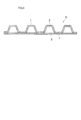
- FIG. 4 shows an example of a top sheet disclosed in Patent Document 1.
- the composite sheet S constituting the top sheet is formed by laminating a first sheet 1 formed with a large number of convex portions 3 and a flat second sheet 2 having no such convex portions 3. The welded portion 7 is joined.
- the first sheet 1 having the plurality of convex portions 3 is in contact with the skin surface, and thus the texture is excellent.
- the so-called heat seal is used as a joining means.
- the joining is executed by pressing a heated roll or the like against the sheet and melting the material of the sheet. At that time, parts of the sheet other than the welded part 7 are also heated, and the texture of the sheet is impaired.
- the gap between the ultrasonic horn and the anvil drum affects the bonding state.
- the anvil drum will be heated by the heat generated by the joining. In that case, the anvil drum expands due to heat, the outer diameter of the anvil drum increases, and the joining state decreases.
- an object of the present invention is to improve the texture of the composite sheet and improve the bonding state of the composite sheet in the composite sheet manufacturing apparatus and method.
- the composite sheet manufacturing apparatus of the present invention comprises means T for conveying the first sheet 1; Shaping means for forming irregularities on the first sheet 1; Introducing means for introducing the second sheet 2 into the shaped transport path CP of the first sheet 1 and superimposing the second sheet 2 on the first sheet 1; Ultrasonic bonding means as means for intermittently bonding the first sheet 1 and the second sheet 2 to generate a composite sheet S; And a cooling means for cooling the joined portion of the first sheet 1 and the second sheet 2 and / or the joined portion.
- the ultrasonic bonding means includes an ultrasonic horn H that performs the bonding in cooperation with the anvil drum AD
- the cooling means includes a first cooling means for cooling the first region A1 from the introduction point P1 of the second sheet 2 to the horn H by the introduction means in the anvil drum AD, and / or the horn H
- a second cooling means is provided for cooling the second region A2 from the facing portion of the anvil drum AD to the derivation point P2 where the composite sheet S is led out from the anvil drum AD.
- the manufacturing method includes a step of conveying the first sheet 1; A shaping step of forming irregularities on the first sheet 1; An introduction step of introducing the second sheet 2 into the shaped transport path CP of the first sheet 1 and superimposing the second sheet 2 on the first sheet 1; An ultrasonic bonding step as a step of intermittently bonding the first sheet 1 and the second sheet 2 to generate a composite sheet S; A cooling step of cooling in advance the joined portion or the joined portion of the first sheet 1 and the second sheet 2 that are overlapped.
- the cooling means cools the joined portion (first region) or the joined portion (second region) of the first and second sheets. Therefore, not only the first and second sheets can be cooled, but also when the anvil drum, which is a part of the ultrasonic bonding means, is heated by friction with the horn, it can be cooled. Therefore, it can suppress that the site
- the expansion of the anvil drum due to heat can be suppressed, so that the increase in the outer diameter of the anvil drum can be suppressed. Therefore, the gap (distance) between the anvil drum and the ultrasonic horn is maintained at an appropriate value, and an improvement in the joining state can be expected.
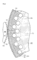
- FIG. 1 is a schematic configuration diagram of a manufacturing apparatus showing an embodiment of the present invention.
- FIG. 2 is an enlarged sectional view showing the shaping means.
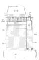
- FIG. 3 is a cross-sectional view showing the negative pressure portion.
- FIG. 4 is an enlarged sectional view showing an example of the composite sheet.
- a more specific structure of the manufacturing apparatus includes a shaping roller MR that forms irregularities on the first sheet 1 conveyed from upstream to downstream along the surface of the anvil drum AD; An introduction roller IR that introduces the second sheet 2 into the conveyance path CP of the first sheet 1 downstream of the shaping roller MR and superimposes the second sheet 2 on the first sheet 1; An ultrasonic horn H that generates a composite sheet S by intermittently joining the first sheet 1 and the second sheet 2 in cooperation with the anvil drum AD downstream of the introduction roller IR.
- the composite sheet S is derived from the first area A1 from the introduction point P1 of the second sheet 2 to the horn H by the introduction roller IR in the anvil drum AD and / or the horn H in the anvil drum AD. Cooling means for cooling the second region A2 up to the derivation point P2.
- the present manufacturing method includes a shaping step of forming irregularities with the shaping roller MR on the first sheet 1 conveyed from upstream to downstream along the surface of the anvil drum AD; An introduction step in which the introduction roller IR introduces the second sheet 2 into the conveyance path CP of the first sheet 1 downstream of the shaping roller MR and overlaps the second sheet 2 on the first sheet 1; The step of generating the composite sheet S by intermittently joining the first sheet 1 and the second sheet 2 in cooperation with the anvil drum AD and the ultrasonic horn H downstream of the introduction roller IR.
- the composite sheet S is derived from the first area A1 from the introduction point P1 of the second sheet 2 to the horn H by the introduction roller IR in the anvil drum AD and / or the horn H in the anvil drum AD.
- the cooling means cools the second region A2 up to the derivation point P2.
- the cooling means is configured to blow the gas G toward the first and second sheets 1 and 2 in the first area A1, and the first area C2 in the second area A2.
- each gas spraying device sprays gas on the first and second sheets in the first or second region in the vicinity of the horn, whereby the first and second sheets are cooled, and the anvil drum is Cooled in the first and / or second region.
- the first and second sheets 1 and 2 have air permeability
- a negative pressure part B for adsorbing the first and second sheets 1 and 2 with a negative pressure is formed inside the anvil drum AD that conveys the first and second sheets 1 and 2.
- the first and / or second blowing devices C1 and C2 define a gas discharge port J through which the gas G is blown toward the negative pressure part B.
- the negative pressure part is not provided, after the gas from the blowing device is blown onto the sheets, most of the gas is reflected by the sheets and does not pass through both sheets, and reaches the surface of the anvil drum AD. It will flow in the atmosphere without turbulence. In that case, the cooling effect of both the sheets and the anvil drum AD may not be sufficiently obtained.
- the gas discharged from the gas discharge port of the spraying device is sucked into the negative pressure portion inside the anvil drum. Therefore, the gas blown onto the first and second sheets is sucked into the negative pressure part and passes through the fine holes in both sheets, cooling both sheets and cooling the heated surface layer portion of the anvil drum. Therefore, the cooling effect of both sheets and the anvil drum is enhanced.
- the ratio of the gas that passes through the first and second sheets and contacts the anvil drum is remarkably increased. That is, after the gas has contacted the surface layer portion of the anvil drum through the air-permeable sheet, the gas is sucked into the negative pressure portion of the anvil drum. Thus, the proportion of gas that contacts the anvil drum is significantly increased.
- the composite sheet S may be a top sheet of a disposable wearing article, for example.
- the convex portion 3 may have a trapezoidal cross section, a hemispherical shell shape, or the like.
- the top sheet absorbs liquid and is liquid permeable and has air permeability to prevent stuffiness. Therefore, both the first and second sheets 1 and 2 constituting the top sheet have air permeability.
- the first and second sheets having air permeability may be, for example, thermoplastic non-woven fabrics, or may exhibit air permeability through through holes formed in the welded portion 7.
- the manufacturing apparatus includes an anvil drum AD, a shaping roller MR, ultrasonic bonding means, and first and second introduction rollers 10, IR.
- the anvil drum AD constitutes a conveying means T together with the first introduction roller 10 for introducing the first sheet 1.
- the conveying means T conveys the first sheet 1 from upstream to downstream along the surface of the anvil drum AD.
- the anvil drum AD and the shaping roller MR constitute shaping means for forming irregularities on the first sheet 1.
- a large number of concave portions D1 are provided on the outer peripheral surface of the anvil drum AD in FIG. 2, while a large number of convex portions M1 are provided on the outer peripheral surface of the shaping roller MR.
- the first sheet 1 (FIG. 1) is sandwiched between the concave portion D1 and the convex portion M1, the concave portions D1 are fitted into the convex portions M1 one after another, and are applied like the first sheet 1 in FIG. Shaped to form irregularities.
- the second introduction roller IR shown in FIG. 1 constitutes (second) introduction means, and introduces the second sheet 2 into the conveyance path CP of the first sheet 1 downstream of the shaping roller MR to introduce the first sheet.
- the second sheet 2 is overlaid on the sheet 1.
- the introduction roller IR and the anvil drum AD constitute another conveying means for conveying the second sheet 2.
- the ultrasonic joining means includes an anvil drum AD, an ultrasonic horn H that applies vibration energy to the two sheets S1 and S2 in cooperation with the anvil drum AD, and ultrasonic vibration to the ultrasonic horn H, respectively. And a sonic device 20 to be generated.
- the horn H is loaded with high-frequency mechanical vibration, and the two sheets 1 and 2 passing between the ultrasonic horn H and the anvil drum AD are welded to each other by friction heat and joined. That is, the horn H generates the composite sheet S by intermittently joining the first sheet 1 and the second sheet 2 in cooperation with the anvil drum AD downstream of the introduction roller IR.
- ultrasonic horn H for example, an ultrasonic horn described in JP-T-10-513128 may be used.
- a seal pattern may be formed on the surface of the anvil drum AD.
- the first sheet 1 is introduced from the introduction point PO into the conveyance path CP along the anvil drum AD.
- the second sheet 2 is introduced from the introduction point P1 into the conveyance path CP along the anvil drum AD.
- the generated composite sheet S is derived from the derived point P2.
- route CP is comprised by the outer peripheral surface of the anvil drum AD, for example.
- the horn H is close to the anvil drum AD through the both sheets 1 and 2 at the tip of the ultrasonic bonding apparatus.
- First and second blowing devices C1 and C2 are arranged in the vicinity of the anvil drum AD so that the gas G is blown immediately upstream and immediately downstream of the horn H in the conveyance path CP of the first sheet 1, respectively. Yes. As will be described later, the first and second blowing devices C1 and C2 cool the first region A1 and the second region A2 of the anvil drum AD, respectively.
- the first region A1 is a region from the introduction point P1 of the second sheet 2 by the introduction roller IR to the upstream end of the horn H in the anvil drum AD.
- the second region A2 is a region from the downstream end of the horn H in the anvil drum AD to a derivation point P2 where the composite sheet S is derived.
- the first and second blowing devices C1 and C2 blow the gas G onto the first and second sheets 1 and 2 in the first and / or second regions A1 and A2, respectively.
- the gas from the blowing devices C1 and C2 may be air or nitrogen, or may be a gas cooled with another refrigerant.
- the first and second blow-out devices C1 and C2 have a gas discharge port J that blows the gas G toward a negative pressure portion B described later. Further, the discharge ports J of the blowing devices C1 and C2 may be formed long in the axial direction of the rotating wheel D2 of the anvil drum AD as shown in FIG.
- the negative pressure part B indicated by a broken line in FIG. 1 is formed inside the anvil drum AD, and adsorbs the first and second sheets 1 and 2 with negative pressure.
- the details of the negative pressure part B will be described.
- the anvil drum AD includes a rotating wheel D2 and a fixed wheel D3.
- the rotating wheel D2 rotates around the rotation center D4, and the fixed wheel D3 is fixed to a frame (not shown).
- the fixed ring D3 is formed with a cavity C3 to which an introduction pipe Cp for sucking a negative pressure of gas is connected. As indicated by a broken line in FIG. 1, the cavity C3 is provided in a part of the fixed ring D3. That is, the cavity C3 is provided in an arc shape corresponding to a section from the introduction point PO to the derivation point P2.
- each suction hole B1 extends in the radial direction of the anvil drum AD and communicates with the lateral hole D5, and communicates with the cavity C3 (FIG. 3) in the section of the negative pressure part B of FIG. That is, each suction hole B1 in FIG. 3 constitutes the negative pressure part B while communicating with the cavity C3.
- the negative pressure portion B in FIG. 1 prevents the first sheet 1 from being displaced relative to the anvil drum AD and retains the convex portion 3 (FIG. 4).
- the first sheet 1 shown in FIG. 1 is guided to the first introduction roller 10 and introduced into the anvil drum AD at the introduction point PO, and is conveyed from upstream to downstream along the surface of the anvil drum AD. Concavities and convexities are formed on the first sheet 1 by the shaping roller MR shown in FIG.
- the introduction roller IR introduces the second sheet 2 into the conveyance path CP of the first sheet 1, and the unevenness is formed on the first sheet.
- the second sheet 2 is stacked on the first sheet.
- the anvil drum AD and the ultrasonic horn H cooperate with each other downstream of the introduction roller IR in FIG. 1 to form the first sheet 1 and the second sheet 2 in FIG. It joins intermittently in parts (welding part 7) other than the part to be done. Thereby, the composite sheet S is generated.
- the composite sheet S is continuously generated from the introduction of the first sheet 1 and the second sheet 2 in FIG. 1, the negative pressure in the cavity C3 in FIG. 3 is always maintained during operation.
- the gas G is always ejected from the first blowing device C1 and the second blowing device C2 in FIG.
- the first area A1 and the second area A2 are cooled by the cooling means.
- the gas G ejected from the first blowing device C1 is blown to the first region A1 from the introduction point P1 of the second sheet 2 by the introduction roller IR in the anvil drum AD to the horn H.
- the gas G ejected from the second blowing device C2 is blown to the second region A2 from the horn H to the derivation point P2 where the composite sheet S is led out in the anvil drum AD.
- the gas G passes through the first and second sheets 1 and 2 having air permeability and is sucked into the negative pressure part B. Therefore, both the sheets 1 and 2 and the anvil drum AD can be cooled immediately upstream of the horn H.
- the gas G passes through the air-permeable composite sheet S and is sucked into the negative pressure part B. Therefore, it is possible to cool both the sheets 1 and 2 and the portion of the anvil drum AD that are heated immediately downstream of the horn H.
- the worn article may be a sanitary product instead of pants or diapers.
- the composite sheet S may not be a top sheet.
- the negative pressure part B is not always necessary.
- the anvil drum may be provided with a heater for temperature control. Accordingly, such changes and modifications are to be construed as within the scope of the present invention as defined by the claims.
- the present invention can be employed for a top sheet of a disposable wearing article.
- First sheet 2 Second sheet 20: Sonic device A1: First region A2: Second region AD: Anvil drum B: Negative pressure part C1: First blowing device C2: Second blowing device CP: Conveyance path G : Gas H: Ultrasonic horn IR: Introduction roller MR: Shaping roller P1: Introduction point P2: Derivation point S: Composite sheet
Landscapes
- Health & Medical Sciences (AREA)
- Life Sciences & Earth Sciences (AREA)
- Engineering & Computer Science (AREA)
- Biomedical Technology (AREA)
- Heart & Thoracic Surgery (AREA)
- Vascular Medicine (AREA)
- Epidemiology (AREA)
- Animal Behavior & Ethology (AREA)
- General Health & Medical Sciences (AREA)
- Public Health (AREA)
- Veterinary Medicine (AREA)
- Absorbent Articles And Supports Therefor (AREA)
- Lining Or Joining Of Plastics Or The Like (AREA)
Abstract
本発明の複合シートは第1シート(1)を搬送する手段(T)と、第1シート(1)に凹凸を形成する賦形手段と、賦形された第1シート(1)の搬送経路(CP)に第2シート(2)を導入して第1シート(1)に第2シート(2)を重ねる導入手段と、第1シート(1)と第2シート(2)とを間欠的に接合して複合シート(S)を生成する手段としての超音波接合手段と、重ねられた第1シート(1)および第2シート(2)の接合部分あるいは接合される部分を冷却する冷却手段とを備える。
Description
本発明は複合シートの製造装置および製造方法に関する。
従来より、前記複合シートの一種として、例えば着用物品のトップシートは公知である(特許文献1)。前記トップシートは着用物品の肌面に接触する。そのため、トップシートには肌ざわりの良い表面となるような風合いが要求される。
図4は前記特許文献1に開示された、トップシートの一例を示す。この図において、前記トップシートを構成する複合シートSは多数の凸部3が賦形された第1シート1と、そのような凸部3を有しない平坦な第2シート2とが互いに積層された溶着部分7で接合されている。
かかる複合シートTは前記多数の凸部3を有する第1シート1が肌面に接し、そのため、前記風合いに優れる。
接合の手段としては、いわゆるヒートシールが用いられている。しかし、ヒートシールでは加熱したロール等をシートに押し付け、シートの材料を溶融することで前記接合を実行する。その際、溶着部分7以外のシートの部分も加熱されてしまい、シートの風合いが損なわれる。
一方、接続手段として超音波接合を用い場合、シートに対する熱の影響を低減することができる。しかし、熱の影響を受けやすい素材では同様の問題が生じる。
また、超音波接合では、超音波ホーンとアンビルドラムとの隙間が接合状態に影響する。接合により生じた熱でアンビルドラムが加熱されるだろう。その場合、アンビルドラムが熱により膨張して、アンビルドラムの外径が大きくなり、接合状態が低下する。
したがって、本発明の目的は、複合シートの製造装置および製造方法において、複合シートの風合いを向上させ、また、複合シートの接合状態を向上させることである。
本発明の複合シートの製造装置は、第1シート1を搬送する手段Tと、
前記第1シート1に凹凸を形成する賦形手段と、
賦形された前記第1シート1の搬送経路CPに第2シート2を導入して前記第1シート1に前記第2シート2を重ねる導入手段と、
前記第1シート1と前記第2シート2とを間欠的に接合して複合シートSを生成する手段としての超音波接合手段と、
重ねられた前記第1シート1および前記第2シート2の接合部分、および/または、接合される部分を冷却する冷却手段とを備える。
前記第1シート1に凹凸を形成する賦形手段と、
賦形された前記第1シート1の搬送経路CPに第2シート2を導入して前記第1シート1に前記第2シート2を重ねる導入手段と、
前記第1シート1と前記第2シート2とを間欠的に接合して複合シートSを生成する手段としての超音波接合手段と、
重ねられた前記第1シート1および前記第2シート2の接合部分、および/または、接合される部分を冷却する冷却手段とを備える。
本製造装置において好ましくは、前記超音波接合手段はアンビルドラムADと協働して前記接合を実行する超音波ホーンHを備え、
前記冷却手段は、前記アンビルドラムADにおける前記導入手段による前記第2シート2の導入ポイントP1から前記ホーンHまでの第1領域A1を冷却する第1冷却手段、、および/または、前記ホーンHが対向する前記アンビルドラムADの部分から前記複合シートSが前記アンビルドラムADから導出される導出ポイントP2までの第2領域A2を冷却する第2冷却手段を備える。
前記冷却手段は、前記アンビルドラムADにおける前記導入手段による前記第2シート2の導入ポイントP1から前記ホーンHまでの第1領域A1を冷却する第1冷却手段、、および/または、前記ホーンHが対向する前記アンビルドラムADの部分から前記複合シートSが前記アンビルドラムADから導出される導出ポイントP2までの第2領域A2を冷却する第2冷却手段を備える。
かかる製造装置を用いて、複合シートは以下のように製造される。すなわち、本製造方法は第1シート1を搬送する工程と、
前記第1シート1に凹凸を形成する賦形工程と、
賦形された前記第1シート1の搬送経路CPに第2シート2を導入して前記第1シート1に前記第2シート2を重ねる導入工程と、
前記第1シート1と前記第2シート2とを間欠的に接合して複合シートSを生成する工程としての超音波接合工程と、
重ねられた前記第1シート1および前記第2シート2の接合部分あるいは接合される部分を予め冷却する冷却工程とを備える。
前記第1シート1に凹凸を形成する賦形工程と、
賦形された前記第1シート1の搬送経路CPに第2シート2を導入して前記第1シート1に前記第2シート2を重ねる導入工程と、
前記第1シート1と前記第2シート2とを間欠的に接合して複合シートSを生成する工程としての超音波接合工程と、
重ねられた前記第1シート1および前記第2シート2の接合部分あるいは接合される部分を予め冷却する冷却工程とを備える。
本発明において、冷却手段は第1および第2シートの接合部分(第1領域)または接合される部分(第2領域)を冷却する。そのため、第1および第2シートを冷却できるだけでなく、超音波接合手段の一部であるアンビルドラムがホーンとの摩擦で昇温しても、これを冷却することができる。
したがって、前記接合部分以外の複合シートの部位が熱により変質するのを抑制でき、複合シートの風合いが損なわれるのを抑制できる。
したがって、前記接合部分以外の複合シートの部位が熱により変質するのを抑制でき、複合シートの風合いが損なわれるのを抑制できる。
また、アンビルドラムの熱による膨張を抑制でき、そのため、アンビルドラムの外径が大きくなるのを抑制できる。したがって、アンビルドラムと超音波ホーンとの間のギャップ(距離)が適切な値に保たれ、接合状態の向上が期待できる。
より具体的な本製造装置の構造は、アンビルドラムADの表面に沿って上流から下流に搬送される第1シート1に凹凸を形成する賦形ローラMRと、
前記賦形ローラMRよりも下流において前記第1シート1の搬送経路CPに第2シート2を導入して前記第1シート1に前記第2シート2を重ねる導入ローラIRと、
前記導入ローラIRよりも下流において前記アンビルドラムADと協働して前記第1シート1と前記第2シート2とを間欠的に接合することで複合シートSを生成する超音波ホーンHとを備えた複合シートの製造装置において、
前記アンビルドラムADにおける前記導入ローラIRによる前記第2シート2の導入ポイントP1から前記ホーンHまでの第1領域A1、および/または、前記アンビルドラムADにおける前記ホーンHから前記複合シートSが導出される導出ポイントP2までの第2領域A2を冷却する冷却手段を備える。
前記賦形ローラMRよりも下流において前記第1シート1の搬送経路CPに第2シート2を導入して前記第1シート1に前記第2シート2を重ねる導入ローラIRと、
前記導入ローラIRよりも下流において前記アンビルドラムADと協働して前記第1シート1と前記第2シート2とを間欠的に接合することで複合シートSを生成する超音波ホーンHとを備えた複合シートの製造装置において、
前記アンビルドラムADにおける前記導入ローラIRによる前記第2シート2の導入ポイントP1から前記ホーンHまでの第1領域A1、および/または、前記アンビルドラムADにおける前記ホーンHから前記複合シートSが導出される導出ポイントP2までの第2領域A2を冷却する冷却手段を備える。
より具体的な本製造方法は、アンビルドラムADの表面に沿って上流から下流に搬送される第1シート1に賦形ローラMRで凹凸を形成する賦形工程と、
前記賦形ローラMRよりも下流において前記第1シート1の搬送経路CPに導入ローラIRが第2シート2を導入して前記第1シート1に前記第2シート2を重ねる導入工程と、
前記導入ローラIRよりも下流において前記アンビルドラムADと超音波ホーンHとが協働して前記第1シート1と前記第2シート2とを間欠的に接合することで複合シートSを生成する工程とを備えた複合シートSの製造方法において、
前記アンビルドラムADにおける前記導入ローラIRによる前記第2シート2の導入ポイントP1から前記ホーンHまでの第1領域A1、および/または、前記アンビルドラムADにおける前記ホーンHから前記複合シートSが導出される導出ポイントP2までの第2領域A2を冷却手段が冷却する冷却工程を備える。
前記賦形ローラMRよりも下流において前記第1シート1の搬送経路CPに導入ローラIRが第2シート2を導入して前記第1シート1に前記第2シート2を重ねる導入工程と、
前記導入ローラIRよりも下流において前記アンビルドラムADと超音波ホーンHとが協働して前記第1シート1と前記第2シート2とを間欠的に接合することで複合シートSを生成する工程とを備えた複合シートSの製造方法において、
前記アンビルドラムADにおける前記導入ローラIRによる前記第2シート2の導入ポイントP1から前記ホーンHまでの第1領域A1、および/または、前記アンビルドラムADにおける前記ホーンHから前記複合シートSが導出される導出ポイントP2までの第2領域A2を冷却手段が冷却する冷却工程を備える。
これらの場合において、好ましくは、前記冷却手段は、前記第1領域A1における前記第1および第2シート1,2に向かって気体Gを吹き出す第1吹出装置C1と、前記第2領域A2における前記第1および第2シート1,2に向って気体Gを吹出す第2吹出装置C2とを備える。
この場合、気体の各吹付装置はホーンの近傍の第1または第2領域において第1および第2シートに気体を吹き付け、これにより、第1および第2シートが冷却されると共に、アンビルドラムが第1および/または第2領域において冷却される。
好ましくは、前記第1および第2シート1,2は通気性を有し、
前記第1および第2シート1,2を搬送する前記アンビルドラムADの内部には前記第1および第2シート1,2を負圧で吸着する負圧部Bが形成され、
前記第1および/または第2吹出装置C1,C2は前記負圧部Bに向かって前記気体Gを吹き出す気体吐出口Jを規定する。
前記第1および第2シート1,2を搬送する前記アンビルドラムADの内部には前記第1および第2シート1,2を負圧で吸着する負圧部Bが形成され、
前記第1および/または第2吹出装置C1,C2は前記負圧部Bに向かって前記気体Gを吹き出す気体吐出口Jを規定する。
仮に、前記負圧部を設けていないと、前記吹出装置からの気体がシートに吹き付けられた後に、シートで反射され気体の大半は両シートを通過せず、また、アンビルドラムADの表面に到達せずに雰囲気中に乱流となって流れるであろう。その場合、気体による両シートやアンビルドラムADの冷却効果が十分に得られないかもしれない。
これに対し、本実施形態では、吹付装置の気体吐出口から吐出された気体はアンビルドラムの内部の負圧部に吸引される。そのため、第1および第2シートに吹き付けられた気体は、負圧部に吸引されて両シートの微細な孔を通過し、両シートを冷却すると共にアンビルドラムの昇温した表層部分を冷却する。したがって、両シートおよびアンビルドラムの冷却効果が高まる。
特に、吹出装置からの気体がアンビルドラムの内部の負圧部に吸引されるので、気体が第1および第2シートを通過して前記アンビルドラムに接触する気体の割合が著しく増大する。
すなわち、通気性を有するシートを通って気体がアンビルドラムの表層部に接触した後に、アンビルドラムの負圧部に吸引される。したがって、アンビルドラムに接触する気体の割合が著しく増大する。
すなわち、通気性を有するシートを通って気体がアンビルドラムの表層部に接触した後に、アンビルドラムの負圧部に吸引される。したがって、アンビルドラムに接触する気体の割合が著しく増大する。
その結果、複合シートの風合いが向上し、また、複合シートの接合状態が向上する。
1つの前記各実施態様または下記の実施例に関連して説明および/または図示した特徴は、1つまたはそれ以上の他の実施態様または他の実施例において同一または類似な形で、および/または他の実施態様または実施例の特徴と組み合わせて、または、その代わりに利用することができる。
本発明は、添付の図面を参考にした以下の好適な実施例の説明からより明瞭に理解されるであろう。しかし、実施例および図面は単なる図示および説明のためのものであり、本発明の範囲を定めるために利用されるべきものではない。本発明の範囲は請求の範囲によってのみ定まる。添付図面において、複数の図面における同一の部品番号は、同一または相当部分を示す。
本発明の実施例の説明に先立って本発明により生成される複合シートSの一例について図4を用いて説明する。
図4において複合シートSは例えば使い捨て着用物品のトップシートであってもよい。なお、凸部3の形状は断面台形状であってもよいし、半球殻状等であってもよい。
図4において複合シートSは例えば使い捨て着用物品のトップシートであってもよい。なお、凸部3の形状は断面台形状であってもよいし、半球殻状等であってもよい。
前記トップシートは吸液するため液透過性で、かつ、ムレ防止のための通気性を有する。したがって、前記トップシートを構成する第1および第2シート1、2は共に通気性を有する。通気性を有する第1および第2シートは例えば熱可塑性の不織布であってもよいし、溶着部分7に形成された貫通孔を介して通気性を発揮するものであってもよい。
つぎに、本製造装置の一例を図1~図3に基づいて説明する。
図1に示すように、本製造装置はアンビルドラムADと、賦形ローラMRと、超音波接合手段と第1および第2導入ローラ10,IRを備える。
図1に示すように、本製造装置はアンビルドラムADと、賦形ローラMRと、超音波接合手段と第1および第2導入ローラ10,IRを備える。
前記アンビルドラムADは第1シート1を導入する第1導入ローラ10と共に搬送手段Tを構成する。搬送手段TはアンビルドラムADの表面に沿って上流から下流に向かって第1シート1を搬送する。
前記アンビルドラムADと前記賦形ローラMRは第1シート1に凹凸を形成する賦形手段を構成する。本実施例の場合、図2のアンビルドラムADの外周面には多数の凹部D1が設けられ、一方、前記賦形ローラMRの外周面には多数の凸部M1が設けられている。前記凹部D1と凸部M1との間に第1シート1(図1)を挟みながら、前記各凹部D1が凸部M1に次々に嵌まり込んで、図4の第1シート1のように賦形されて凹凸が形成される。
図1の前記第2導入ローラIRは(第2)導入手段を構成し、前記賦形ローラMRよりも下流において前記第1シート1の搬送経路CPに第2シート2を導入して前記第1シート1に前記第2シート2を重ねる。前記導入ローラIRとアンビルドラムADとは第2シート2を搬送する別の搬送手段を構成する。
前記超音波接合手段は、アンビルドラムADと、前記アンビルドラムADと協働して前記両シートS1,S2に振動エネルギーを印加する超音波ホーンHと、前記超音波ホーンHに各々超音波振動を発生させるソニック装置20とを備える。
前記ホーンHには周波数の高い機械的振動が負荷されて、前記超音波ホーンHとアンビルドラムADとの間を通過する2枚のシート1,2同士を摩擦熱で互いに溶着して接合する。すなわち、前記ホーンHは前記導入ローラIRよりも下流において前記アンビルドラムADと協働して前記第1シート1と前記第2シート2とを間欠的に接合することで複合シートSを生成する。
前記超音波ホーンHとしては、たとえば、特表平10-513128号に記載の超音波ホーンが用いられてもよい。アンビルドラムADの表面にシールパターンが形成されていてもよい。
前記第1シート1は導入ポイントPOから前記アンビルドラムADに沿った搬送経路CPに導入される。前記第2シート2は導入ポイントP1から前記アンビルドラムADに沿った搬送経路CPに導入される。生成された複合シートSは導出ポイントP2から導出される。なお、前記搬送経路CPは、例えば、アンビルドラムADの外周面で構成される。
前記ホーンHは超音波接合装置の先端部分で前記両シート1,2を介してアンビルドラムADに近接している。前記第1シート1の搬送経路CPにおける前記ホーンHの直上流と直下流に気体Gが吹き付けられるように、それぞれ、第1および第2吹出装置C1,C2がアンビルドラムADの近傍に配置されている。後述するように、第1および第2吹出装置C1,C2は、各々、アンビルドラムADの第1領域A1および第2領域A2を冷却する。
前記第1領域A1は前記アンビルドラムADにおける前記導入ローラIRによる前記第2シート2の導入ポイントP1から前記ホーンHの上流端までの領域である。前記第2領域A2は前記アンビルドラムADにおける記ホーンHの下流端から前記複合シートSが導出される導出ポイントP2までの領域である。
第1および第2吹出装置C1,C2は、それぞれ、前記第1および/または第2領域A1,A2において前記第1および第2シート1,2に気体Gを吹き付ける。前記吹出装置C1,C2からの気体はエアーやチッ素であってもよく、また、別の冷媒で冷却された気体であってもよい。
前記第1および第2吹出装置C1,C2は後述する負圧部Bに向かって前記気体Gを吹き付ける気体吐出口Jを有する。また、前記吹出装置C1,C2の吐出口Jは図3のようにアンビルドラムADの回転輪D2の軸方向に長く形成されていてもよい。
前記第1および第2吹出装置C1,C2は後述する負圧部Bに向かって前記気体Gを吹き付ける気体吐出口Jを有する。また、前記吹出装置C1,C2の吐出口Jは図3のようにアンビルドラムADの回転輪D2の軸方向に長く形成されていてもよい。
図1の破線で示す前記負圧部Bは前記アンビルドラムADの内部に形成され、前記第1および第2シート1,2を負圧で吸着する。以下、前記負圧部Bの詳細について説明する。
図3に示すように、前記アンビルドラムADは回転輪D2および固定輪D3を備える。回転輪D2は回転中心D4のまわりを回転し、固定輪D3は図示しないフレームに固定されている。
前記固定輪D3には気体を負圧吸引する導入パイプCpが連結された空洞部C3が形成されている。図1の破線で示すように前記空洞部C3は前記固定輪D3の一部に設けられている。すなわち、前記空洞部C3は前記導入ポイントPO~導出ポイントP2に至る区間に対応して円弧状に設けられている。
図3の前記回転輪D2には前記固定輪D3に連通するマニホールドDmが形成されている。図2のように、前記マニホールドDmは多数の横孔D5と多数の吸引孔B1とを備える。前記各吸引孔B1はアンビルドラムADの径方向に延び前記横孔D5に連通し、図1の負圧部Bの区間において前記空洞部C3(図3)に連通する。すなわち、図3の前記各吸引孔B1は前記空洞部C3に連通している間において前記負圧部Bを構成する。図1の負圧部BはアンビルドラムADに対し第1シート1が位置ズレするのを防止すると共に凸部3(図4)を保形する。
つぎに、複合シートSの製造方法について説明する。
図1の第1シート1が第1導入ローラ10に案内されて導入ポイントPOでアンビルドラムADに導入され、アンビルドラムADの表面に沿って上流から下流に搬送される。第1シート1は図2の賦形ローラMRにより凹凸が形成される。
図1の第1シート1が第1導入ローラ10に案内されて導入ポイントPOでアンビルドラムADに導入され、アンビルドラムADの表面に沿って上流から下流に搬送される。第1シート1は図2の賦形ローラMRにより凹凸が形成される。
図1の前記賦形ローラMRよりも下流の導入ポイントP1において、前記第1シート1の搬送経路CPに導入ローラIRが第2シート2を導入して、前記凹凸が形成された前記第1シート1に前記第2シート2を重ねる。
図1の前記導入ローラIRよりも下流において、前記アンビルドラムADと超音波ホーンHとが協働して、図4の前記第1シート1と前記第2シート2とを、凸部3が形成される部分以外の部分(溶着部分7)において間欠的に接合する。これにより複合シートSが生成される。
図1の前記第1シート1および第2シート2の導入から複合シートSの生成は連続的に行われるが、運転中は常時、図3の前記空洞部C3の負圧が維持される。一方、運転中は常時、図1の第1吹出装置C1および第2吹出装置C2から気体Gが噴出される。これによって、第1領域A1および第2領域A2が冷却手段により冷却される。
すなわち、前記アンビルドラムADにおける前記導入ローラIRによる前記第2シート2の導入ポイントP1から前記ホーンHまでの第1領域A1には、第1吹出装置C1から噴出された気体Gが吹き付けられる。一方、前記アンビルドラムADにおける前記ホーンHから前記複合シートSが導出される導出ポイントP2までの第2領域A2には、第2吹出装置C2から噴出された気体Gが吹き付けられる。
前記第1領域A1において、前記気体Gは通気性を有する第1および第2シート1、2を通過して負圧部Bに吸引される。そのため、ホーンHの直上流において両シート1,2およびアンビルドラムADを冷却することができる。
一方、前記第2領域A2において、前記気体Gは通気性を有する複合シートSを通過して負圧部Bに吸引される。そのため、ホーンHの直下流において昇温した両シート1,2およびアンビルドラムADの部分を冷却することができる。
以上のとおり、図面を参照しながら好適な実施例を説明したが、当業者であれば本明細書を見て、自明な範囲で種々の変更および修正を容易に想定するであろう。
たとえば、着用物品はパンツやオムツではなく、生理用品であってもよい。また、複合シートSはトップシートでなくてもよい。
また、第1吹出装置C1または第2吹出装置C2のいずれか一方のみを設けてもよい。更に、負圧部Bは必ずしも必要ではない。
また、アンビルドラムには温調のためのヒータが設けられていてもよい。
したがって、そのような変更および修正は、請求の範囲から定まる本発明の範囲内のものと解釈される。
たとえば、着用物品はパンツやオムツではなく、生理用品であってもよい。また、複合シートSはトップシートでなくてもよい。
また、第1吹出装置C1または第2吹出装置C2のいずれか一方のみを設けてもよい。更に、負圧部Bは必ずしも必要ではない。
また、アンビルドラムには温調のためのヒータが設けられていてもよい。
したがって、そのような変更および修正は、請求の範囲から定まる本発明の範囲内のものと解釈される。
本発明は使い捨て着用物品のトップシートなどに採用することができる。
1:第1シート 2:第2シート
20:ソニック装置 A1:第1領域 A2:第2領域
AD:アンビルドラム B:負圧部
C1:第1吹出装置 C2:第2吹出装置 CP:搬送経路
G:気体 H:超音波ホーン IR:導入ローラ MR:賦形ローラ
P1:導入ポイント P2:導出ポイント S:複合シート
20:ソニック装置 A1:第1領域 A2:第2領域
AD:アンビルドラム B:負圧部
C1:第1吹出装置 C2:第2吹出装置 CP:搬送経路
G:気体 H:超音波ホーン IR:導入ローラ MR:賦形ローラ
P1:導入ポイント P2:導出ポイント S:複合シート
Claims (7)
- 第1シート1を搬送する手段Tと、
前記第1シート1に凹凸を形成する賦形手段と、
賦形された前記第1シート1の搬送経路CPに第2シート2を導入して前記第1シート1に前記第2シート2を重ねる導入手段と、
前記第1シート1と前記第2シート2とを間欠的に接合して複合シートSを生成する手段としての超音波接合手段と、
重ねられた前記第1シート1および前記第2シート2の接合部分、および/または、接合される部分を冷却する冷却手段とを備える、複合シートの製造装置。 - 請求項1において、前記超音波接合手段はアンビルドラムADと協働して前記接合を実行する超音波ホーンHを備え、
前記冷却手段は、前記アンビルドラムADにおける前記導入手段による前記第2シート2の導入ポイントP1から前記ホーンHまでの第1領域A1を冷却する第1冷却手段、および/または、前記ホーンHが対向する前記アンビルドラムADの部分から前記複合シートSが前記アンビルドラムADから導出される導出ポイントP2までの第2領域A2を冷却する第2冷却手段を備える、製造装置。 - アンビルドラムADの表面に沿って上流から下流に搬送される第1シート1に凹凸を形成する賦形ローラMRと、
前記賦形ローラMRよりも下流において前記第1シート1の搬送経路CPに第2シート2を導入して前記第1シート1に前記第2シート2を重ねる導入ローラIRと、
前記導入ローラIRよりも下流において前記アンビルドラムADと協働して前記第1シート1と前記第2シート2とを間欠的に接合することで複合シートSを生成する超音波ホーンHとを備えた複合シートの製造装置において、
前記アンビルドラムADにおける前記導入ローラIRによる前記第2シート2の導入ポイントP1から前記ホーンHまでの第1領域A1、および/または、前記アンビルドラムADにおける前記ホーンHから前記複合シートSが導出される導出ポイントP2までの第2領域A2を冷却する冷却手段を備える、ことを特徴とする複合シート2の製造装置。 - 請求項2もしくは3において、前記冷却手段は、
前記第1領域A1における前記第1および第2シート1,2に向かって気体Gを吹き出す第1吹出装置C1と、前記第2領域A2における前記第1および第2シート1,2に向って気体Gを吹出す第2吹出装置C2とを備える、製造装置。 - 請求項4において、前記第1および第2シート1,2は通気性を有し、
前記第1および第2シート1,2を搬送する前記アンビルドラムADの内部には前記第1および第2シート1,2を負圧で吸着する負圧部Bが形成され、
前記第1および/または第2吹出装置C1,C2は前記負圧部Bに向かって前記気体Gを吹き出す気体吐出口Jを規定する、製造装置。 - 第1シート1を搬送する工程と、
前記第1シート1に凹凸を形成する賦形工程と、
賦形された前記第1シート1の搬送経路CPに第2シート2を導入して前記第1シート1に前記第2シート2を重ねる導入工程と、
前記第1シート1と前記第2シート2とを間欠的に接合して複合シートSを生成する工程としての超音波接合工程と、
重ねられた前記第1シート1および前記第2シート2の接合部分および/または接合される部分を予め冷却する冷却工程とを備える、複合シートの製造方法。 - アンビルドラムADの表面に沿って上流から下流に搬送される第1シート1に賦形ローラMRで凹凸を形成する賦形工程と、
前記賦形ローラMRよりも下流において前記第1シート1の搬送経路CPに導入ローラIRが第2シート2を導入して前記第1シート1に前記第2シート2を重ねる導入工程と、
前記導入ローラIRよりも下流において前記アンビルドラムADと超音波ホーンHとが協働して前記第1シート1と前記第2シート2とを間欠的に接合することで複合シートSを生成する工程とを備えた複合シートSの製造方法において、
前記アンビルドラムADにおける前記導入ローラIRによる前記第2シート2の導入ポイントP1から前記ホーンHまでの第1領域A1、および/または、前記アンビルドラムADにおける前記ホーンHから前記複合シートSが導出される導出ポイントP2までの第2領域A2を冷却手段が冷却する冷却工程を備える、ことを特徴とする複合シートの製造方法。
Priority Applications (1)
| Application Number | Priority Date | Filing Date | Title |
|---|---|---|---|
| JP2018522429A JP6956715B2 (ja) | 2016-06-08 | 2017-05-29 | 複合シートの製造装置および製造方法 |
Applications Claiming Priority (2)
| Application Number | Priority Date | Filing Date | Title |
|---|---|---|---|
| JP2016-114204 | 2016-06-08 | ||
| JP2016114204 | 2016-06-08 |
Publications (1)
| Publication Number | Publication Date |
|---|---|
| WO2017212969A1 true WO2017212969A1 (ja) | 2017-12-14 |
Family
ID=60579029
Family Applications (1)
| Application Number | Title | Priority Date | Filing Date |
|---|---|---|---|
| PCT/JP2017/019880 Ceased WO2017212969A1 (ja) | 2016-06-08 | 2017-05-29 | 複合シートの製造装置および製造方法 |
Country Status (2)
| Country | Link |
|---|---|
| JP (1) | JP6956715B2 (ja) |
| WO (1) | WO2017212969A1 (ja) |
Citations (4)
| Publication number | Priority date | Publication date | Assignee | Title |
|---|---|---|---|---|
| JP2004137655A (ja) * | 2002-09-25 | 2004-05-13 | Kao Corp | 不織布の嵩回復方法 |
| JP2013126528A (ja) * | 2011-11-15 | 2013-06-27 | Kao Corp | パンツ型着用物品の製造方法 |
| WO2014084066A1 (ja) * | 2012-11-30 | 2014-06-05 | 株式会社瑞光 | 複合シート材とこれを用いた使い捨て着用物品および複合シート材の製造方法と製造装置 |
| JP2016087423A (ja) * | 2015-06-04 | 2016-05-23 | ユニ・チャーム株式会社 | 凹凸シートの製造方法、及び、凹凸シートの製造装置 |
-
2017
- 2017-05-29 WO PCT/JP2017/019880 patent/WO2017212969A1/ja not_active Ceased
- 2017-05-29 JP JP2018522429A patent/JP6956715B2/ja active Active
Patent Citations (4)
| Publication number | Priority date | Publication date | Assignee | Title |
|---|---|---|---|---|
| JP2004137655A (ja) * | 2002-09-25 | 2004-05-13 | Kao Corp | 不織布の嵩回復方法 |
| JP2013126528A (ja) * | 2011-11-15 | 2013-06-27 | Kao Corp | パンツ型着用物品の製造方法 |
| WO2014084066A1 (ja) * | 2012-11-30 | 2014-06-05 | 株式会社瑞光 | 複合シート材とこれを用いた使い捨て着用物品および複合シート材の製造方法と製造装置 |
| JP2016087423A (ja) * | 2015-06-04 | 2016-05-23 | ユニ・チャーム株式会社 | 凹凸シートの製造方法、及び、凹凸シートの製造装置 |
Also Published As
| Publication number | Publication date |
|---|---|
| JPWO2017212969A1 (ja) | 2019-04-04 |
| JP6956715B2 (ja) | 2021-11-02 |
Similar Documents
| Publication | Publication Date | Title |
|---|---|---|
| JP6228814B2 (ja) | シート融着体の製造装置及び製造方法 | |
| JP6078561B2 (ja) | 基材を継ぎ合わせるための、装置及び方法 | |
| EP3473414B1 (en) | A method and apparatus for producing a breathable web and related web | |
| JP2013124428A5 (ja) | 積層不織布の製造方法 | |
| JP5766252B2 (ja) | パンツ型着用物品及びその製造方法 | |
| WO2013088969A1 (ja) | 積層不織布およびその製造方法 | |
| JP2008231609A (ja) | 吸引装置、シートの搬送方法、吸収体の製造方法及び不織布の嵩回復方法 | |
| WO2019054314A1 (ja) | 着用物品の製造装置および製造方法 | |
| JP2012120775A (ja) | 超音波接合装置、それを用いたウエブの接合方法及びそれを用いたパンツ型着用物品の製造方法 | |
| JP2015008943A (ja) | パンツ型着用物品及びその製造方法 | |
| JP2019183343A (ja) | シート状マスクの製造方法 | |
| WO2015064606A1 (ja) | 使い捨ておむつ | |
| JP6389113B2 (ja) | シート融着体の製造方法及び製造装置 | |
| JP6956715B2 (ja) | 複合シートの製造装置および製造方法 | |
| WO2016076224A1 (ja) | 着用物品の製造方法および製造装置 | |
| JP6247899B2 (ja) | シート融着体の製造装置及び製造方法 | |
| CN111629702B (zh) | 片体、片体的制造装置以及片体的制造方法 | |
| JP7092954B1 (ja) | 伸縮積層シート、使い捨て着用物品、伸縮積層シートの製造方法および製造装置 | |
| CN112972121A (zh) | 一种复合片材的制造装置、系统及其制造方法 | |
| JP2011120745A (ja) | 吸収性物品の製造方法 | |
| JP5838285B1 (ja) | 吸収性物品の製造方法、及び、吸収性物品の製造装置 | |
| JP2012251274A (ja) | 網状体及びその製造方法 | |
| JP2026014015A (ja) | 不織布製造方法および不織布製造装置 | |
| WO2019151064A1 (ja) | 弾性シートの製造方法及び製造装置、伸縮複合シートの製造方法及び製造装置、並びに伸縮複合シート | |
| CN112972120A (zh) | 复合片材的制造装置、系统及其制造方法 |
Legal Events
| Date | Code | Title | Description |
|---|---|---|---|
| ENP | Entry into the national phase |
Ref document number: 2018522429 Country of ref document: JP Kind code of ref document: A |
|
| 121 | Ep: the epo has been informed by wipo that ep was designated in this application |
Ref document number: 17810148 Country of ref document: EP Kind code of ref document: A1 |
|
| NENP | Non-entry into the national phase |
Ref country code: DE |
|
| 122 | Ep: pct application non-entry in european phase |
Ref document number: 17810148 Country of ref document: EP Kind code of ref document: A1 |