WO2017212801A1 - 熱式流量計 - Google Patents
熱式流量計 Download PDFInfo
- Publication number
- WO2017212801A1 WO2017212801A1 PCT/JP2017/015839 JP2017015839W WO2017212801A1 WO 2017212801 A1 WO2017212801 A1 WO 2017212801A1 JP 2017015839 W JP2017015839 W JP 2017015839W WO 2017212801 A1 WO2017212801 A1 WO 2017212801A1
- Authority
- WO
- WIPO (PCT)
- Prior art keywords
- passage
- flow
- flow meter
- thermal
- measurement
- Prior art date
- Legal status (The legal status is an assumption and is not a legal conclusion. Google has not performed a legal analysis and makes no representation as to the accuracy of the status listed.)
- Ceased
Links
Images










Classifications
-
- G—PHYSICS
- G01—MEASURING; TESTING
- G01F—MEASURING VOLUME, VOLUME FLOW, MASS FLOW OR LIQUID LEVEL; METERING BY VOLUME
- G01F1/00—Measuring the volume flow or mass flow of fluid or fluent solid material wherein the fluid passes through a meter in a continuous flow
- G01F1/68—Measuring the volume flow or mass flow of fluid or fluent solid material wherein the fluid passes through a meter in a continuous flow by using thermal effects
- G01F1/684—Structural arrangements; Mounting of elements, e.g. in relation to fluid flow
- G01F1/6842—Structural arrangements; Mounting of elements, e.g. in relation to fluid flow with means for influencing the fluid flow
-
- F—MECHANICAL ENGINEERING; LIGHTING; HEATING; WEAPONS; BLASTING
- F02—COMBUSTION ENGINES; HOT-GAS OR COMBUSTION-PRODUCT ENGINE PLANTS
- F02M—SUPPLYING COMBUSTION ENGINES IN GENERAL WITH COMBUSTIBLE MIXTURES OR CONSTITUENTS THEREOF
- F02M35/00—Combustion-air cleaners, air intakes, intake silencers, or induction systems specially adapted for, or arranged on, internal-combustion engines
- F02M35/10—Air intakes; Induction systems
- F02M35/10373—Sensors for intake systems
- F02M35/10386—Sensors for intake systems for flow rate
-
- G—PHYSICS
- G01—MEASURING; TESTING
- G01F—MEASURING VOLUME, VOLUME FLOW, MASS FLOW OR LIQUID LEVEL; METERING BY VOLUME
- G01F1/00—Measuring the volume flow or mass flow of fluid or fluent solid material wherein the fluid passes through a meter in a continuous flow
-
- G—PHYSICS
- G01—MEASURING; TESTING
- G01F—MEASURING VOLUME, VOLUME FLOW, MASS FLOW OR LIQUID LEVEL; METERING BY VOLUME
- G01F1/00—Measuring the volume flow or mass flow of fluid or fluent solid material wherein the fluid passes through a meter in a continuous flow
- G01F1/68—Measuring the volume flow or mass flow of fluid or fluent solid material wherein the fluid passes through a meter in a continuous flow by using thermal effects
- G01F1/684—Structural arrangements; Mounting of elements, e.g. in relation to fluid flow
Definitions
- the present invention relates to a thermal flow meter.
- the conventional flow rate measuring device includes a first fluid passage portion and a second fluid passage portion.
- the first fluid passage portion includes a surface on which the flow rate measuring element is mounted and a passage forming surface of the sub passage.
- the second fluid passage portion includes a surface opposite to a surface on which the flow rate measuring element is mounted and a passage forming surface of the sub passage.
- the passage forming surface of the first fluid passage portion facing the upstream side of the fluid flow with respect to the flow measuring element directs the fluid flow to the flow measuring element. It has such an inclined surface.
- This inclined surface is composed of two or more surfaces in different directions.
- the pattern of the heating resistor rides on the fluid flow. It can suppress flowing toward. For this reason, it is possible to suppress damage or contamination of the flow rate measuring element composed of the heating resistor pattern, and it is excellent in dust resistance even in an unsteady flow field such as pulsating flow, and it is difficult to cause characteristic errors and is reliable.
- a high flow rate measuring device can be provided (see the same document, paragraph 0009, etc.).
- the conventional thermal flow meter is measured by a flow rate measuring element when a fluid pulsation causes a flow velocity of the fluid flowing through the first fluid passage portion to be lower than a flow velocity of the fluid flowing through the second fluid passage portion. There is a possibility that the measured flow rate is lower than the actual flow rate, and the measurement error increases.
- This invention is made in view of the said subject, and it aims at providing the thermal type flow meter which can reduce the measurement error at the time of the pulsation of a fluid compared with the past.
- a thermal flow meter includes a sub-passage that takes in a part of a fluid flowing through the main passage, and a flow rate measurement unit disposed in the sub-passage.
- the sub-passage includes a first passage provided on the measurement surface side of the flow rate measurement unit, a second passage provided on the back side of the flow rate measurement unit, and an inlet of the first passage.
- An inclined passage provided on the upstream side in the forward flow direction of the fluid in the first passage, and the inclined passage is closer to the second passage side than the flow rate measuring unit with respect to the forward flow direction. It has the 1st inclined surface which inclines toward the 1st channel
- the thermal flow meter of the present invention when the fluid pulsates, the fluid flowing in the sub passage is caused to flow by the first inclined surface of the inclined passage provided upstream in the forward flow direction from the inlet of the first passage. Deflection can be performed from the passage side toward the first passage side. As a result, the flow rate of the fluid flowing in the forward flow direction through the first passage can be increased more than before, and the measured flow velocity can be suppressed from lowering than the actual flow velocity, and the measurement error can be reduced more than before.
- FIG. 2B is a left side view of the thermal flow meter shown in FIG. 2A.
- FIG. 2B is a rear view of the thermal flow meter shown in FIG. 2A.
- FIG. 2B is a right side view of the thermal flow meter shown in FIG. 2A.
- FIG. 2C is a cross-sectional view of the thermal flow meter shown in FIG.
- FIG. 4 is a cross-sectional view of the thermal flow meter shown in FIG. 2C taken along line IVA-IVA.
- FIG. 4 is a cross-sectional view of the thermal flow meter shown in FIG. 2C taken along line IVB-IVB. The typical expanded view of the subchannel
- FIG. 2B is a front view of the front cover of the thermal flow meter shown in FIG. 2A.
- FIG. 6B is a rear view of the front cover of the thermal flow meter shown in FIG. 6A.
- the front view of the back cover of the thermal type flow meter shown in FIG. 2C The rear view of the back cover of the thermal type flow meter shown to FIG. 7A.
- path of the thermal type flow meter shown in FIG. The figure which shows the flow velocity of the fluid which flows through the subchannel
- path of the thermal type flow meter which concerns on Embodiment 2 of this invention.
- path of the thermal type flow meter which concerns on Embodiment 3 of this invention.
- path of the thermal type flow meter which concerns on Embodiment 4 of this invention.
- path of the thermal type flow meter which concerns on Embodiment 5 of this invention.
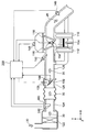
- FIG. 1 is a schematic diagram showing an example of an electronic fuel injection type internal combustion engine control system including a thermal type flow meter 300 according to Embodiment 1 of the present invention.
- the intake air is sucked from the air cleaner 122 as the measurement target gas 30, and is a main passage 124 such as an intake pipe, a throttle body 126, and an intake manifold. It is guided to the combustion chamber of the engine cylinder 112 through 128.
- the flow rate of the gas 30 to be measured which is the intake air led to the combustion chamber, is measured by the thermal flow meter 300, and fuel is supplied from the fuel injection valve 152 based on the measured flow rate, and the gas to be measured is the intake air.
- the gas 30 is introduced into the combustion chamber in the state of an air-fuel mixture.
- the fuel injection valve 152 is provided in the intake port of the internal combustion engine, and the fuel injected into the intake port is mixed with the measured gas 30 as intake air to become an air-fuel mixture. It is led to the combustion chamber through and burns to generate mechanical energy.
- the thermal flow meter 300 can be used not only for the method of injecting fuel into the intake port of the internal combustion engine shown in FIG. 1 but also for the method of directly injecting fuel into each combustion chamber.
- the basic concept of the control parameter measurement method including the method of using the thermal flow meter 300 and the control method of the internal combustion engine including the fuel supply amount and the ignition timing are substantially the same.
- a system for injecting fuel into an intake port is shown.
- the fuel and air led to the combustion chamber are in a mixed state of fuel and air, and are explosively burned by spark ignition of the spark plug 154 to generate mechanical energy.
- the burned gas is guided from the exhaust valve 118 to the exhaust pipe, and is exhausted from the exhaust pipe to the outside as exhaust 24.
- the flow rate of the gas 30 to be measured which is the intake air led to the combustion chamber, is controlled by the throttle valve 132 whose opening degree changes based on the operation of the accelerator pedal.
- the fuel supply amount is controlled based on the flow rate of the intake air guided to the combustion chamber, and the driver controls the flow rate of the intake air guided to the combustion chamber by controlling the opening degree of the throttle valve 132, thereby
- the mechanical energy generated by the engine can be controlled.
- the flow rate and temperature of the gas 30 to be measured which is taken in from the air cleaner 122 and flows through the main passage 124, are measured by the thermal flow meter 300, and an electrical signal representing the measured flow rate and temperature of the intake air is a thermal type.
- the output of the throttle angle sensor 144 that measures the opening degree of the throttle valve 132 is input to the control device 200, and the positions and states of the engine piston 114, the intake valve 116, and the exhaust valve 118 of the internal combustion engine, and the rotation of the internal combustion engine.
- the output of the rotation angle sensor 146 is input to the control device 200.
- the output of the oxygen sensor 148 is input to the control device 200 in order to measure the state of the mixture ratio between the fuel amount and the air amount from the state of the exhaust 24.
- the control device 200 outputs the fuel injection amount and the ignition timing based on the output of the thermal flow meter 300, for example, the flow rate, humidity, and temperature of the intake air and the rotational speed of the internal combustion engine from the rotation angle sensor 146. Is calculated. Based on these calculation results, the amount of fuel supplied from the fuel injection valve 152 and the ignition timing ignited by the spark plug 154 are controlled. In actuality, the fuel supply amount and the ignition timing are the intake air temperature measured by the thermal flow meter 300, the change state of the throttle angle, the change state of the engine speed, and the state of the air-fuel ratio measured by the oxygen sensor 148. Is controlled based on.
- the control device 200 further controls the amount of air that bypasses the throttle valve 132 by the idle air control valve 156 in the idle operation state of the internal combustion engine, and controls the rotational speed of the internal combustion engine in the idle operation state.
- the fuel supply amount and ignition timing which are the main control amounts of the internal combustion engine, are all calculated using the output of the thermal flow meter 300 as a main parameter. Therefore, improvement in measurement accuracy of the thermal flow meter 300, suppression of changes over time, and improvement in reliability are important for improving vehicle control accuracy and ensuring reliability.
- improvement in measurement accuracy of the thermal flow meter 300, suppression of changes over time, and improvement in reliability are important for improving vehicle control accuracy and ensuring reliability.
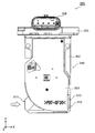
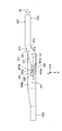
- FIG. 2A is a front view of the thermal flow meter 300 according to the present embodiment.
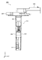
- 2B, 2C, and 2D are a left side view, a rear view, and a right side view of the thermal type flow meter shown in FIG. 2A, respectively.
- the thermal flow meter 300 includes a housing 310 including a housing 302, a front cover 303, and a back cover 304.
- the front cover 303 and the back cover 304 are formed in a thin plate shape and have a wide flat cooling surface. For this reason, the thermal flow meter 300 has a configuration in which the air resistance is reduced and the casing 310 is easily cooled by the gas to be measured flowing through the main passage 124.
- the housing 310 has, for example, a substantially rectangular parallelepiped flat shape, and is inserted into the intake pipe and disposed in the main passage 124 as shown in FIG. Although details will be described later, the casing 310 defines a sub-passage that takes in a part of the measurement target gas 30 that is a fluid flowing through the main passage 124.
- the length direction of the casing 310 that is substantially parallel to the flow of the gas 30 to be measured in the main passage 124 is the X-axis direction, the casing perpendicular to the length direction and substantially parallel to the radial direction of the main passage 124.
- Each part of the thermal flow meter 300 using an XYZ orthogonal coordinate system in which the height direction of 310 is the Y-axis direction and the thickness direction of the casing 310 perpendicular to the length direction and the height direction is the Z-axis direction. May be explained.
- the casing 310 has a shape that extends long along the axis from the outer wall of the main passage 124 toward the center, but has a flat shape with a small thickness as shown in FIGS. 2B and 2D. . That is, the casing 310 of the thermal flow meter 300 has a thin shape along the side surface and a substantially rectangular shape on the front surface. As a result, the thermal flow meter 300 can be provided with a sufficiently long sub-passage with a reduced fluid resistance with respect to the gas to be measured 30.
- a flange 305 for fixing the thermal flow meter 300 to the intake pipe, and a connector which is an external connection part exposed to the outside of the intake pipe for electrical connection with an external device 306 is provided.
- the housing 302 is supported in a cantilever manner by fixing the flange 305 to the intake pipe.
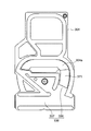
- FIG. 3A is a front view of the thermal flow meter 300 shown in FIG. 2A with the front cover 303 removed.
- 3B is a rear view of the thermal flow meter 300 shown in FIG. 2C with the back cover 304 removed.
- An inlet 311 for taking a part of the measured gas 30 such as intake air that is a fluid flowing through the main passage 124 into the sub-passage 307 is provided at a position on the distal end side of the housing 302 and upstream in the main flow direction. Yes. As described above, the inlet 311 for taking the measured gas 30 flowing through the main passage 124 into the sub-passage 307 is provided on the front end side of the housing 310 extending from the flange 305 toward the center in the radial direction of the main passage 124.
- the inlet 311 is provided at the distal end portion of the thin and long casing 310 extending from the flange 305 toward the center of the main passage 124, so that the flow velocity at the center portion of the main passage 124 is provided. Can be taken into the sub-passage 307.
- a first outlet 312 and a second outlet 313 for returning the measurement target gas 30 from the auxiliary passage 307 to the main passage 124 are provided at a position on the distal end side of the housing 302 and on the downstream side in the main flow direction.
- the first outlet 312 and the second outlet 313 are arranged side by side in the thickness direction (Z-axis direction) of the housing 302.
- the first outlet 312 and the second outlet 313, which are the discharge ports of the auxiliary passage 307 are provided at the distal ends of the casing 310, so that the gas that has flowed through the auxiliary passage 307 is allowed to flow through the main passage 124 having a high flow velocity. It is possible to return to the vicinity of the central part.
- the circuit package 400 provided is molded integrally.
- the housing 302 is formed with auxiliary passage grooves 330 and 331 for defining the auxiliary passage 307.
- the sub-passage grooves 330 and 331 are recessed in the front and back surfaces of the housing 302, respectively.
- the front cover 303 and the back cover 304 are attached to the front and back surfaces of the housing 302, and the auxiliary passage grooves 330 and 331 of the housing 302 are covered with the front cover 303 and the rear cover 304, thereby defining the housing 310 that defines the auxiliary passage 307.
- the housing 302 having such a structure is formed by molding the housing 302 and the auxiliary passage grooves 330 and 331 on the front and back sides using, for example, molds disposed on both surfaces of the housing 302 in a resin molding process for molding the housing 302. Can be collectively performed.
- the auxiliary passage groove 331 provided on the back side of the housing 302 includes a linear groove portion 332 for defining the linear passage 307 ⁇ / b> A in a part of the auxiliary passage 307 and a branch passage in a part of the auxiliary passage 307. And a branch groove portion 333 for defining 307B.
- the straight groove portion 332 extends in a straight line along the main flow direction (X-axis positive direction) of the measurement target gas 30 at the distal end portion of the housing 302, and one end communicates with the inlet 311 of the housing 302. Communicates with the first outlet 312 of the housing 302.
- the straight groove portion 332 includes a straight portion 332A extending from the inlet 311 with a substantially constant cross-sectional shape, and a throttle portion 332B in which the groove width gradually decreases as it moves from the straight portion 332A toward the first outlet 312. Yes.
- the first outlet 312 serves as a discharge port for discharging a fluid flowing through the straight passage 307 ⁇ / b> A of the sub passage 307, that is, a part of the measurement target gas 30.
- the branch groove portion 333 branches from the straight portion 332A of the straight groove portion 332 and proceeds toward the base end side of the housing 302 while being curved, and is provided at the center portion in the height direction (Y-axis direction) which is the longitudinal direction of the housing 302. It communicates with the measurement channel 341.
- the branch groove portion 333 has an upstream end communicating with the side wall surface 332 a positioned on the proximal end side of the housing 302, and the bottom wall surface 333 a is a straight portion 332 A of the straight groove portion 332. It is flush with the bottom wall of the floor.
- the accommodation groove part 333A is provided in the side wall surface inside the curve of the branch groove part 333.
- the accommodation groove 333A has a recess 333B.
- the recess 333B takes in water that has entered the accommodation groove 333A, and discharges it to the outside of the housing 310 through a drain hole 376 formed at a position facing the recess 333B of the back cover 304, as shown in FIG. 2C.
- the measurement channel 341 is formed so as to penetrate the housing 302 from the front side to the back side in the thickness direction.
- a flow path exposed portion 430 of the circuit package 400 is disposed so as to protrude.
- the branch groove 333 communicates with the measurement flow path 341 on the upstream side of the sub-passage 307 with respect to the flow path exposure part 430 of the circuit package 400.
- the auxiliary passage groove 331 that defines the auxiliary passage 307 is a steeply inclined portion that defines an inclined passage, which will be described later, on the upstream side of the flow of the measurement target gas 30 in the measurement channel 341.
- the branch groove portion 333 of the sub passage groove 331 that defines the branch passage 307B of the sub passage 307 is directed from the linear groove portion 332 toward the measurement flow path 341 in the height direction of the housing 302 (Y-axis direction).
- the main passage 124 extends while curving in a direction opposite to the main flow direction of the gas 30 to be measured (X-axis negative direction).
- the branch passage 307B of the sub-passage 307 defined by the branch groove 333 is directed from the distal end side of the housing 302 toward the base end side, which is the flange 305 side, while drawing a curve, and the measurement channel 341 is located closest to the flange 305. Is provided.
- the gas to be measured 30 flowing through the sub-passage 307 flows in the direction opposite to the main flow direction of the main passage 124 (X-axis negative direction).
- the branch groove portion 333 has a three-dimensional shape in which the groove depth in the thickness direction (Z-axis direction) of the housing 302 gradually increases toward the measurement channel 341. (See FIG. 4A).
- the branch groove portion 333 has a steeply inclined portion 333 d that becomes deeper and deeper in front of the measurement channel 341.
- the steeply inclined portion 333d is covered on the surface 431 side of the measurement flow channel 341 on which the measurement surface 451a of the flow rate measurement unit 451 is provided, of the front surface 431 and the rear surface 432 of the flow channel exposure unit 430 of the circuit package 400. It has the effect
- the sub passage groove 330 provided on the front side of the housing 302 shown in FIG. 3A defines a downstream portion of the branch passage 307B of the sub passage 307.
- One end of the downstream portion of the branch passage 307B defined by the sub passage groove 330 communicates with the upstream portion of the branch passage 307B on the back side of the housing 302 via the measurement flow path 341, and the other end of the housing 302. It communicates with the second outlet 313 formed on the tip side of the.
- the sub-passage groove 330 provided on the front side of the housing 302 gradually curves toward the downstream side in the main flow direction as it moves to the front end side of the housing 302, and the gas to be measured at the front end portion of the housing 302. 30 extends linearly toward the downstream side in the main flow direction, and has a shape in which the groove width gradually decreases toward the second outlet 313.
- the measurement target gas 30 and the foreign matter that have passed through the measurement flow path 341 flow through the downstream portion of the branch passage 307 ⁇ / b> B of the sub passage 307 defined by the sub passage groove 330 provided on the front side of the housing 302. It is discharged from the outlet 313 and returned to the main passage 124.
- the channel exposed portion 430 of the circuit package 400 is directed from the wall surface of the branch groove portion 333 of the sub-passage groove 331 that defines the measurement channel 341 toward the front end side of the housing 302 in the height direction of the housing 302 (Y-axis direction). And protrudes into the measurement channel 341.
- the channel exposure part 430 has a thickness in the thickness direction (Z-axis direction) of the housing 302 and is formed in a rectangular plate shape along the flow direction of the measurement target gas 30 flowing through the measurement channel 341.
- the channel exposure unit 430 supports the flow rate measurement unit 451 and functions as a support unit that arranges the flow rate measurement unit 451 in the sub-passage 307.
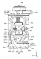
- FIG. 4A is a cross-sectional view taken along line IVA-IVA of the thermal flow meter 300 shown in FIG. 2C.
- 4B is a cross-sectional view taken along line IVB-IVB of the thermal flow meter 300 shown in FIG. 2C.
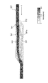
- the sub-passage 307 includes a first passage 351 provided on the measurement surface 451a side of the flow measurement unit 451 and a second passage 352 provided on the back surface 451b side of the flow measurement unit 451 in the measurement flow channel 341. . Further, the sub-passage 307 is an inclination provided upstream of the forward flow direction F of the fluid in the first passage 351 relative to the inlet 351a of the first passage 351, that is, in the forward flow direction F of the measured gas 30 in the first passage 351. A passage 361 is provided.
- the air that is the measurement target gas 30 flows along the forward direction F of the measurement target gas 30 in the first passage 351 of the measurement channel 341.
- heat transfer is performed with the measurement target gas 30 via the measurement surface 451a which is a heat transfer surface provided in the flow rate measurement unit 451, and the flow rate is measured.
- the measurement principle of this flow rate can use a general measurement principle as a thermal type flow meter. If the flow rate of the gas 30 to be measured flowing through the main passage 124 can be measured based on the measurement value measured by the flow rate measurement unit 451 as in the thermal flow meter 300 of the present embodiment, the flow rate measurement unit
- the configuration of 451 is not particularly limited.
- the thermal flow meter 300 of the present embodiment is configured so that the measurement flow path 341 of the sub-passage 307 has a higher flow rate in the first passage 351 than the inlet 351a of the first passage 351 provided on the measurement surface 451a side of the flow measurement unit 451. It has the characteristic in the inclination channel
- FIG. The inclined passage 361 is closer to the second passage 352 than the flow rate measuring unit 451, and the first inclined surface 371 is inclined from the second passage 352 toward the first passage 351 with respect to the forward flow direction F of the measurement target gas 30. have.
- the thermal flow meter 300 of the present embodiment includes the flat casing 310 that is disposed in the main passage 124 and defines the sub-passage 307, but is disposed in the sub-passage 307.
- the measurement surface 451a of the flow rate measurement unit 451 is substantially perpendicular to the thickness direction (Z-axis direction) of the housing 310.
- the sub-passage 307 has a straight passage 307A that takes in a part of the gas 30 to be measured, which is a fluid flowing through the main passage 124 (see FIG. 3B). ).
- the sub-passage 307 includes a first outlet 312 that is a discharge port that discharges a part of the measurement target gas 30 that is a fluid that flows through the straight passage 307A, and a forward flow direction of the fluid that flows through the straight passage 307A from the first outlet 312.
- a branch passage 307B that branches off from the straight passage 307A on the upstream side.
- the first passage 351, the second passage 352, and the inclined passage 361 are all provided in the branch passage 307B.
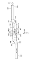
- FIG. 5 is a schematic development view of the auxiliary passage 307 of the thermal flow meter 300 shown in FIGS. 4A and 4B.
- a cross section along the thickness direction (Z-axis direction) of the casing 310 in the portion before and after the measurement flow path 341 of the sub-passage 307 is shown in the thickness direction (Z-axis direction) and length of the casing 310. It expands and represents to the cross section parallel to a direction (X-axis direction).
- the thermal flow meter 300 of the present embodiment includes a sub-passage 307 that takes in a part of the measurement target gas 30 that is a fluid flowing through the main passage 124, and a flow rate measurement unit disposed in the sub-passage 307. 451.
- the sub-passage 307 includes a first passage 351 provided on the measurement surface 451a side of the flow measurement unit 451, a second passage 352 provided on the back surface 451b side of the flow measurement unit 451, and an inlet of the first passage 351.
- an inclined passage 361 provided on the upstream side in the forward flow direction F of the measurement target gas 30 in the first passage 351 with respect to the first passage 351a.
- the inclined passage 361 is closer to the second passage 352 than the flow rate measuring unit 451, and the first inclined surface is inclined from the second passage 352 side toward the first passage 351 side with respect to the forward flow direction F of the measurement target gas 30. 371.
- the inclined passage 361 includes a second inclined surface 372 that faces the first inclined surface 371 in a direction (Z-axis direction) perpendicular to the measurement surface 451 a of the flow rate measuring unit 451. . Similar to the first inclined surface 371, the second inclined surface 372 is inclined from the second passage 352 side toward the first passage 351 side with respect to the forward flow direction F of the measurement target gas 30. As shown in FIG. 3B, the second inclined surface 372 is provided at the bottom of the branch groove portion 333 of the housing 302, and forms a steeply inclined portion 333 d in the branch groove portion 333 of the housing 302.
- the inclination angle ⁇ 2 of the second inclined surface 372 with respect to the forward flow direction F of the measurement target gas 30 is larger than the inclination angle ⁇ 1 of the first inclined surface 371 with respect to the forward flow direction F of the measurement target gas 30. It has become. More specifically, the angle difference between the inclination angle ⁇ 1 of the first inclined surface 371 and the inclination angle ⁇ 2 of the second inclined surface 372 can be, for example, 3 ° or more and 15 ° or less.
- the sub-passage 307 is such that the upstream side of the forward flow direction F of the gas to be measured 30 with respect to the inclined passage 361 is perpendicular to the measurement surface 451 a of the flow rate measurement unit 451 (Z-axis direction). ) Is provided closer to the second passage 352 than the first passage 351.
- the sub-passage 307 is measured with the extension line L1 of the first inclined surface 371 in a cross section that is parallel to the forward flow direction F of the measurement target gas 30 and perpendicular to the measurement surface 451a of the flow rate measurement unit 451.
- the extended line L2 of the surface 451a intersects the upstream side in the forward flow direction F of the measurement target gas 30 with respect to the measurement surface 451a.
- the extension line of the first inclined surface 371 is upstream of the upstream end of the flow path exposure part 430 of the circuit package 400 as the support part of the flow rate measurement part 451. You may make it L1 and the extended line L2 of the measurement surface 451a cross.
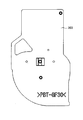
- 6A and 6B are a front view and a rear view of the front cover 303 of the thermal flow meter shown in FIG. 2A, respectively.
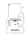
- 7A and 7B are a front view and a rear view, respectively, of the back cover 304 of the thermal flow meter shown in FIG. 2C.
- the front cover 303 and the back cover 304 are components of the housing 310 that defines the sub-passage 307, and each of the sub-passages for defining the sub-passage 307 on the back side facing the housing 302. Grooves 335 and 336 are provided.
- the sub-passage groove 335 of the front cover 303 defines the measurement channel 341 of the sub-passage 307 and the downstream portion thereof together with the sub-passage groove 330 of the housing 302 shown in FIG. 3A.
- the sub-passage groove 336 of the back cover 304 includes a linear groove part 337 for defining a straight passage 307A in a part of the sub-passage 307, A branch groove 338 for defining a branch passage 307B is provided in a part of the sub-passage 307.
- the first inclined surface 371 of the inclined passage 361 shown in FIGS. 4A and 5 is provided at the bottom of the branch groove 338 of the back cover 304 shown in FIG. 7B.
- the first inclined surface 371 is continuously connected to a wall surface 304 a provided at the bottom of the branch groove 338 of the back cover 304.
- the wall surface 304 a defines a measurement channel 341 of the sub-passage 307 and is provided so as to face the second passage 352 on the back surface 451 b side of the flow rate measurement unit 451.
- the wall surface 304a that defines the width of the second passage 352 in the thickness direction (Z-axis direction) of the casing 310, the flow velocity of the measurement target gas 30 flowing through the measurement channel 341 is improved. Can do.
- FIG. 8A is a diagram showing the flow velocity of the fluid flowing through the auxiliary passage 307 of the thermal type flow meter 300 shown in FIG.
- the flow velocity of the gas to be measured 30 flowing through the sub passage 307 is shown in black and white, and the flow velocity of the gas to be measured 30 is higher as the color is darker.
- the gas to be measured 30 is measured by the first inclined surface 371 of the inclined passage 361 provided upstream of the inlet 351a of the first passage 351 of the sub passage 307 in the forward flow direction F.
- the forward flow direction F can be deflected from the second passage 352 side toward the first passage 351 side. Thereby, even at the time of the pulsation of the gas 30 to be measured, the flow velocity of the fluid flowing through the first passage 351 in the forward flow direction F can be increased as compared with the related art.
- FIG. 8B is a diagram showing the flow velocity of the fluid flowing through the sub passage 307 of the thermal flow meter of the comparative example that does not have the first inclined surface 371 shown in FIG. Also in FIG. 8B, similarly to FIG. 8A, the flow velocity of the measurement target gas 30 is indicated by black and white shading.
- the effect of deflecting the flow in the forward flow direction F of the measurement target gas 30 from the second passage 352 side toward the first passage 351 side is small. Therefore, the flow velocity of the gas to be measured 30 flowing through the first passage 351 is smaller than the flow velocity of the gas to be measured 30 flowing through the second passage 352, and the first passage 351 flows in the forward flow direction even when the gas to be measured 30 pulsates. The flow rate of the fluid flowing through F decreases.
- FIG. 9 is a graph showing the flow velocity measurement result by the thermal flow meter 300 of the present embodiment shown in FIG. 8A and the flow velocity measurement result by the thermal flow meter of the comparative example shown in FIG. 8B.
- the horizontal axis is the input flow rate, that is, the actual flow rate of the gas 30 to be measured
- the vertical axis is the output flow rate, that is, the thermal flow meter 300 of the present embodiment and the thermal flow meter of the comparative example.
- the output flow velocity is the input flow rate, that is, the actual flow rate of the gas 30 to be measured.
- the output flow velocity is significantly lower than the input flow velocity in the thermal flow meter of the comparative example, but the output flow velocity is lower in the thermal flow meter 300 of the present embodiment. Is suppressed.
- FIG. 10 is a graph showing an example of the actual fluid flow velocity during pulsation and the fluid flow velocity measured by the thermal flow meter 300 of the present embodiment and the thermal flow meter of the comparative example.
- the horizontal axis represents time
- the vertical axis represents the flow velocity
- the solid line represents the actual flow velocity of the measurement target gas 30, that is, the input flow velocity
- the broken line is measured by the thermal flow meter 300 of the present embodiment.
- the one-dot chain line is the flow rate measured by the thermal flow meter of the comparative example.
- the input flow velocity is changed from 3 [m / s] to a reverse flow state of 0 [m / s] or less with 1 [m / s] as a reference, and the thermal flow meter 300 of the present embodiment.
- the flow velocity of the gas 30 to be measured is measured by the thermal flow meter of the comparative example.
- the thermal type flow meter 300 of the present embodiment as shown in FIG. 8A, the flow rate of the first passage 351 in the forward flow direction F of the gas to be measured 30 increases, and as shown by the broken line in FIG. As a result, the average value V1 of the measured flow velocity becomes substantially equal to the average value V0 of the input flow velocity.
- the flow velocity of the first passage 351 in the forward flow direction F of the gas to be measured 30 decreases and is measured as shown by the one-dot chain line in FIG.
- the maximum value of the flow velocity does not increase sufficiently, and as a result, the measured average value V2 of the flow velocity is lower than the average value V0 of the input flow velocity.
- the average value V1 of the flow velocity is used as the measurement value of the flow velocity, and therefore the average velocity value V1 is smaller than the average velocity value V0 of the actual measurement target gas 30. It is important to suppress this.
- the average value V1 of the flow velocity is shifted to the plus side with respect to the average value V2 of the flow velocity by the thermal flow meter of the comparative example, and the actual measurement target It can approach the average value V0 of the flow velocity of the gas 30.
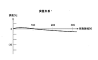
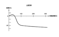
- FIG. 11A and FIG. 11B are graphs showing examples of measurement errors of the thermal flow meter of Embodiment 1 shown in FIG. 8A and the thermal flow meter of the comparative example shown in FIG. 8B, respectively.
- the thermal type flow meter 300 of the present embodiment as shown in FIG. 8A, the flow velocity of the first passage 351 in the forward flow direction F of the measurement target gas 30 increases, so that the measurement target gas 30 Even if the pulsation amplitude of the flow velocity increases, errors in the measured flow velocity can be suppressed.
- the thermal flow meter of the comparative example as shown in FIG.
- the flow velocity of the first passage 351 in the forward flow direction F of the gas to be measured 30 is reduced, so that the pulsation amplitude of the flow velocity of the gas to be measured 30 is reduced.
- the error in the measured flow rate increases.
- the thermal flow meter 300 has the measurement flow path 341 of the sub-passage 307 more than the inlet 351a of the first passage 351 provided on the measurement surface 451a side of the flow measurement unit 451.
- An inclined passage 361 provided on the upstream side in the forward flow direction F of the measurement target gas 30 in the first passage 351 is provided.
- the inclined passage 361 is inclined closer to the second passage 352 than the flow rate measuring unit 451 with respect to the forward flow direction F of the gas 30 to be measured from the second passage 352 toward the first passage 351.
- a surface 371 is provided.
- the thermal flow meter 300 of the present embodiment allows the flow in the forward flow direction F of the measurement target gas 30 from the second passage 352 side to the first passage 351 side by the first inclined surface 371 of the inclined passage 361. Can be deflected towards. Thereby, even at the time of pulsation of the gas to be measured 30, the flow rate of the gas to be measured 30 flowing in the forward flow direction F through the first passage 351 can be increased as compared with the conventional case. Therefore, according to the thermal flow meter 300 of the present embodiment, even when the measurement target gas 30 is pulsating, the flow rate measured by the flow rate measurement unit 451 is suppressed from being lower than the actual flow rate, and the measurement error is reduced. It can be reduced as compared with the prior art.
- the inclined passage 361 faces the first inclined surface 371 in the direction (Z-axis direction) perpendicular to the measurement surface 451a of the flow rate measurement unit 451, as shown in FIG.
- the second inclined surface 372 is provided.
- the second inclined surface 372 is inclined from the second passage 352 side toward the first passage 351 side with respect to the forward flow direction F of the measurement target gas 30, similarly to the first inclined surface 371. This suppresses the generation of vortices in the flow of the measurement target gas 30 deflected by the first inclined surface 371 of the inclination passage 361 and increases the flow rate of the measurement target gas 30 flowing in the forward flow direction F through the first passage 351. Can be made.
- the inclination angle ⁇ 2 of the second inclined surface 372 with respect to the forward flow direction F of the measurement target gas 30 is the inclination angle of the first inclined surface 371 with respect to the forward flow direction F of the measurement target gas 30. It is larger than ⁇ 1. Thereby, it is possible to more effectively suppress vortex generation in the flow of the measurement target gas 30 deflected by the first inclined surface 371 of the inclination passage 361, and the measurement target gas 30 flowing in the forward flow direction F through the first passage 351.
- the flow rate can be increased.
- the angle difference between the inclination angle ⁇ 1 of the first inclined surface 371 and the inclination angle ⁇ 2 of the second inclined surface 372 is, for example, 3 ° or more and 15 ° or less, it is likely to occur in an expanded diameter pipe. Vortices can be suppressed. That is, the angle at which the inclined passage 361 expands is moderated to rectify the flow of the measurement gas 30 in the measurement channel 341 and stabilize the flow of the measurement gas 30 in the first passage 351 and the second passage 352. Can be made.
- the sub-passage 307 has a direction in which the upstream portion in the forward flow direction F of the gas 30 to be measured is perpendicular to the measurement surface 451a of the flow rate measurement unit 451 with respect to the inclined passage 361. It is provided closer to the second passage 352 than the first passage 351 in the (Z-axis direction).
- the flow velocity of the measured gas 30 flowing through the second passage 352 is the flow velocity of the measured gas 30 flowing through the first passage 351.
- the flow velocity of the measurement target gas 30 flowing through the first passage 351 decreases.
- the flow in the forward flow direction F of the gas 30 to be measured is deflected from the second passage 352 side toward the first passage 351 side, and the first passage 351 is forward flowed.
- the flow velocity of the fluid flowing in the direction F can be increased.
- the extension line L1 of the 1st inclined surface 371 and the extension line L2 of the measurement surface 451a are more of the measurement target gas 30 than the measurement surface 451a. It intersects on the upstream side in the forward flow direction F.
- the measurement target gas 30 deflected from the second passage 352 side toward the first passage 351 side by flowing along the first inclined surface 371 can be easily introduced into the first passage 351.
- the extension line L1 of the first inclined surface 371 and the extension line L2 of the measurement surface 451a intersect on the upstream side of the upstream end of the flow path exposed portion 430 of the circuit package 400, the first package is deflected. The measured gas 30 is easily introduced by the first passage 351.
- the thermal flow meter 300 of the present embodiment even when the measurement target gas 30 is pulsating, the flow rate measured by the flow rate measurement unit 451 is suppressed from being lower than the actual flow rate. Measurement errors can be reduced as compared with the prior art.
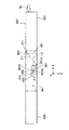
- FIG. 12 is a schematic development view of the auxiliary passage 307 of the thermal flow meter of the present embodiment corresponding to FIG. 5 of the thermal flow meter 300 of the first embodiment.
- the thermal flow meter of the present embodiment will be described focusing on differences from the thermal flow meter 300 of the first embodiment shown in FIG. Except for the configuration described below, the thermal flow meter of the present embodiment has the same configuration as the thermal flow meter of the first embodiment. Therefore, the same parts as those of the thermal flow meter 300 of the first embodiment are denoted by the same reference numerals, and the description thereof is omitted as appropriate.
- the thermal flow meter of the present embodiment has a housing on the wall surface on the second passage 352 side among the wall surfaces of the auxiliary passage 307 facing each other in the thickness direction (Z-axis direction) of the housing 310.
- a convex portion 381 that protrudes in the thickness direction (Z-axis direction) of the body 310 is provided.
- the convex portion 381 has a first inclined surface 371.
- the range in which the first inclined surface 371 is provided is the inclined passage 361 in the sub passage 307 of the thermal type flow meter of the present embodiment.
- the first inclined surface 371 shown in FIG. 12 is provided on the second passage 352 side with respect to the flow rate measurement unit 451, and is similar to the first inclined surface shown in FIG. It inclines toward the 1st channel
- the thermal flow meter of the present embodiment does not have the second inclined surface 372 in the inclined passage 361 of the sub-passage 307, and the upstream portion in the forward flow direction F from the inclined passage 361 of the sub-passage 307 is measured. It is not provided closer to the second passage 352 than the first passage 351 in the direction perpendicular to the surface 451a.
- the thermal flow meter of the present embodiment has the first passage 351, the second passage 352, and the inclined passage 361 in the sub passage 307, and the inclined passage 361.
- the flow in the forward flow direction F of the measurement target gas 30 is directed from the second passage 352 side to the first passage 351 side by the first inclined surface 371 of the inclined passage 361.
- the same effect as that of the thermal flow meter 300 of the first embodiment can be obtained.
- FIG. 13 is a schematic development view of the sub-passage 307 of the thermal flow meter of the present embodiment corresponding to FIG. 5 of the thermal flow meter 300 of the first embodiment.
- the thermal flow meter of the present embodiment will be described focusing on differences from the thermal flow meter 300 of the second embodiment shown in FIG. Except for the configuration described below, the thermal flow meter of the present embodiment has the same configuration as the thermal flow meter of the second embodiment described above. Therefore, the same parts as those of the thermal flow meter of the second embodiment and the thermal flow meter 300 of the first embodiment are denoted by the same reference numerals, and the description thereof is omitted as appropriate.
- the thermal flow meter of the present embodiment has a wall surface 304 a on the second passage 352 side among the wall surfaces of the auxiliary passage 307 facing each other in the thickness direction (Z-axis direction) of the housing 310.
- the casing 310 protrudes in the thickness direction (Z-axis direction).
- the wall surface 304a is provided, for example, by projecting the back surface of the back cover 304.
- a first inclined surface 371 is provided at the end of the upstream wall surface 304 a in the forward flow direction F of the gas to be measured 30 in the sub passage 307.
- the range in which the first inclined surface 371 is provided is the inclined passage 361 in the sub passage 307 of the thermal type flow meter of the present embodiment.
- the thermal flow meter of the present embodiment is similar to the thermal flow meter 300 of the first embodiment shown in FIG. 5 and the thermal flow meter of the second embodiment shown in FIG.
- the inclined passage 361 has a second passage 352 and an inclined passage 361.
- the inclined passage 361 is closer to the second passage 352 than the flow rate measuring unit 451, and from the second passage 352 side to the first passage 351 side with respect to the forward flow direction F. It has the 1st inclined surface 371 which inclines.
- the flow in the forward flow direction F of the measurement target gas 30 is directed from the second passage 352 side to the first passage 351 side by the first inclined surface 371 of the inclined passage 361.
- the same effect as that of the thermal flow meter 300 of the first embodiment and the thermal flow meter of the second embodiment can be obtained.
- FIG. 14 is a schematic development view of the sub-passage 307 of the thermal flow meter of the present embodiment corresponding to FIG. 5 of the thermal flow meter 300 of the first embodiment.
- the thermal flow meter of the present embodiment will be described focusing on differences from the thermal flow meter of the second embodiment shown in FIG. Except for the configuration described below, the thermal flow meter of the present embodiment has the same configuration as the thermal flow meter of the second embodiment described above. Therefore, the same parts as those of the thermal flow meter of the second embodiment and the thermal flow meter 300 of the first embodiment are denoted by the same reference numerals, and the description thereof is omitted as appropriate.
- the flow path exposed portion 430 of the circuit package 400 as the support portion of the flow rate measuring portion 451 is in the forward flow direction F of the measured gas 30 in the first passage 351. Inclined with respect to (X-axis negative direction). More specifically, the surface 431 on the first passage 351 side of the flow path exposed portion 430 is inclined with respect to the forward flow direction F from the second passage 352 side toward the first passage 351 side.
- the first passage 351 is a passage provided on the measurement surface 451a side of the flow measurement unit 451 by the flow passage exposing portion 430 of the circuit package 400 in the sub passage 307. This is a portion overlapping the measurement surface 451a in the thickness direction (Z-axis direction) of the housing 310.
- a portion of the surface 431 of the flow path exposure portion 430 that is inclined with respect to the forward flow direction F is a first inclined surface in a portion upstream of the inlet of the first passage 351 in the forward flow direction F. 371.
- a portion on the upstream side in the forward flow direction F from the inlet 351a of the first passage 351 is an inclined passage 361. .
- the thermal flow meter of the present embodiment has the first passage 351, the second passage 352, and the inclined passage 361 in the sub passage 307, like the thermal flow meters of the second and third embodiments.
- the inclined passage 361 has a first inclined surface 371 inclined toward the first passage 351 side from the second passage 352 side with respect to the forward flow direction F on the second passage 352 side with respect to the flow rate measuring unit 451. .
- the flow in the forward flow direction F of the measurement target gas 30 is directed from the second passage 352 side to the first passage 351 side by the first inclined surface 371 of the inclined passage 361. It can be deflected, and the same effect as the thermal flow meter of the second and third embodiments can be obtained.
- FIG. 15 is a schematic development view of the sub-passage 307 of the thermal flow meter of the present embodiment corresponding to FIG. 5 of the thermal flow meter 300 of the first embodiment.
- the thermal flow meter of the present embodiment will be described focusing on the differences from the thermal flow meter of the first embodiment shown in FIG. Except for the configuration described below, the thermal flow meter of the present embodiment has the same configuration as the thermal flow meter 300 of the first embodiment described above. For this reason, the same parts as those of the thermal flow meter 300 of the first embodiment are denoted by the same reference numerals, and the description thereof is omitted as appropriate.
- the sub passage 307 has a second inclined passage 362 on the downstream side in the forward flow direction F from the outlet 351b of the first passage 351.
- the second inclined passage 362 has a third inclined surface 373 inclined toward the second passage 352 side from the first passage 351 side with respect to the forward flow direction F on the first passage 351 side of the flow rate measuring unit 451. ing.
- the second inclined passage 362 has a fourth inclined surface 374 that faces the third inclined surface 373 in the direction perpendicular to the measurement surface 451a (Z-axis direction). .
- the fourth inclined surface 374 is inclined with respect to the forward flow direction F from the second passage 352 side toward the first passage 351 side.
- the sub-passage 307 has a second passage in a direction (Z-axis direction) in which the downstream side portion of the forward flow direction F from the second inclined passage 362 is perpendicular to the measurement surface 451a. It is provided closer to the first passage 351 than 352.
- the sub-passage 307 has an inclined passage 361 and a second inclined passage 362 having a point-symmetrical configuration with respect to a point on the flow rate measuring unit 451 on the upstream side and the downstream side in the forward flow direction F of the measurement channel 341. And have.
- the thermal flow meter of the present embodiment has the same configuration as the thermal flow meter 300 of the first embodiment, so that the same effect as the thermal flow meter 300 of the first embodiment can be obtained.
- the thermal flow meter of the present embodiment includes the second inclined passage 362, so that the reverse flow direction opposite to the forward flow direction F from the downstream side of the forward flow direction F of the measurement target gas 30 in the measurement channel 341 is provided.
- the measurement target gas 30 flowing in R can be deflected from the first passage 351 side toward the second passage 352 side by the third inclined surface 373.
- the flow rate of the gas to be measured 30 flowing in the second passage 352 in the reverse flow direction R (X-axis positive direction) is increased as compared with the conventional case, and the first passage 351 in the reverse flow direction R.
- the flow velocity of the measurement target gas 30 flowing can be reduced as compared with the conventional method.
- the negative peak of the flow velocity waveform indicated by the broken line in FIG. 10 is shifted to the plus side, and the average velocity V1 measured by the thermal flow meter is changed to the average velocity V0 of the actual measured gas 30. Can be closer.
- the second inclined passage 362 faces the third inclined surface 373 and is inclined with respect to the forward flow direction F from the second passage 352 side toward the first passage 351 side.
- a fourth inclined surface 374 is provided.
- the thermal flow meter of the present embodiment even when the measurement target gas 30 is pulsating, the flow rate measured by the flow rate measurement unit 451 is more effectively suppressed from being reduced than the actual flow rate, The measurement error can be reduced as compared with the conventional case.
Landscapes
- Physics & Mathematics (AREA)
- Fluid Mechanics (AREA)
- Engineering & Computer Science (AREA)
- General Physics & Mathematics (AREA)
- Chemical & Material Sciences (AREA)
- Analytical Chemistry (AREA)
- Combustion & Propulsion (AREA)
- Mechanical Engineering (AREA)
- General Engineering & Computer Science (AREA)
- Measuring Volume Flow (AREA)
Abstract
Description
図1は、本発明の実施形態1に係る熱式流量計300を備えた電子燃料噴射方式の内燃機関制御システムの一例を示す概略図である。このシステムでは、エンジンシリンダ112とエンジンピストン114を備える内燃機関110の動作に基づき、吸入空気が被計測気体30としてエアクリーナ122から吸入され、主通路124であるたとえば吸気管、スロットルボディ126、吸気マニホールド128を介してエンジンシリンダ112の燃焼室に導かれる。
次に、本発明の熱式流量計の実施形態2について、図1から図4Bおよび図6Aから図7Bを援用し、図12を用いて説明する。図12は、前述の実施形態1の熱式流量計300の図5に相当する本実施形態の熱式流量計の副通路307の模式的な展開図である。
次に、本発明の熱式流量計の実施形態3について、図1から図4Bおよび図6Aから図7Bを援用し、図13を用いて説明する。図13は、前述の実施形態1の熱式流量計300の図5に相当する本実施形態の熱式流量計の副通路307の模式的な展開図である。
次に、本発明の熱式流量計の実施形態4について、図1から図4Bおよび図6Aから図7Bを援用し、図14を用いて説明する。図14は、前述の実施形態1の熱式流量計300の図5に相当する本実施形態の熱式流量計の副通路307の模式的な展開図である。
次に、本発明の熱式流量計の実施形態5について、図1から図4Bおよび図6Aから図7Bを援用し、図15を用いて説明する。図15は、前述の実施形態1の熱式流量計300の図5に相当する本実施形態の熱式流量計の副通路307の模式的な展開図である。
124 主通路
300 熱式流量計
307 副通路
307A 直線通路
307B 分岐通路
310 筐体
312 第1出口(排出口)
351 第1通路
351a 入口
351b 第1通路の出口
352 第2通路
361 傾斜通路
362 第2傾斜通路
371 第1傾斜面
372 第2傾斜面
373 第3傾斜面
374 第4傾斜面
451 流量計測部
451a 計測面
451b 背面
F 順流方向
L1 第1傾斜面の延長線
L2 計測面の延長線
θ1 第1傾斜面の傾斜角度
θ2 第2傾斜面の傾斜角度
Claims (9)
- 主通路を流れる流体の一部を取りこむ副通路と、該副通路内に配置された流量計測部と、を備えた熱式流量計であって、
前記副通路は、前記流量計測部の計測面側に設けられた第1通路と、前記流量計測部の背面側に設けられた第2通路と、前記第1通路の入口よりも前記第1通路における前記流体の順流方向の上流側に設けられた傾斜通路と、を有し、
前記傾斜通路は、前記流量計測部よりも第2通路側に、前記順流方向に対して前記第2通路側から第1通路側へ向けて傾斜する第1傾斜面を有することを特徴とする熱式流量計。 - 前記傾斜通路は、前記流量計測部の計測面に垂直な方向において前記第1傾斜面に対向する第2傾斜面を有し、
前記第2傾斜面は、前記順流方向に対して前記第2通路側から前記第1通路側へ向けて傾斜することを特徴とする請求項1に記載の熱式流量計。 - 前記順流方向に対する前記第2傾斜面の傾斜角度は、前記順流方向に対する前記第1傾斜面の傾斜角度よりも大きいことを特徴とする請求項2に記載の熱式流量計。
- 前記副通路は、前記傾斜通路よりも前記順流方向の上流側の部分が、前記流量計測部の計測面に垂直な方向において前記第1通路よりも前記第2通路側に設けられていることを特徴とする請求項1に記載の熱式流量計。
- 前記副通路は、前記順流方向に平行で前記流量計測部の計測面に垂直な断面において、前記第1傾斜面の延長線と前記計測面の延長線とが、前記流計測面よりも前記順流方向の上流側で交差することを特徴とする請求項1に記載の熱式流量計。
- 前記副通路は、前記主通路を流れる前記流体の一部を取りこむ直線通路と、該直線通路を流れる前記流体の一部を排出する排出口と、該排出口よりも前記直線通路を流れる前記流体の順流方向の上流側で前記直線通路から分岐する分岐通路と、を有し、
前記第1通路、前記第2通路、および前記傾斜通路は、前記分岐通路に設けられていることを特徴とする請求項1に記載の熱式流量計。 - 前記主通路内に配置され前記副通路を画定する扁平な筐体を備え、
前記流量計測部の計測面は、前記筐体の厚さ方向に垂直であることを特徴とする請求項1に記載の熱式流量計。 - 前記副通路は、前記第1通路の出口よりも前記順流方向の下流側に第2傾斜通路を有し、
前記第2傾斜通路は、前記流量計測部よりも前記第1通路側に、前記順流方向に対して前記第1通路側から前記第2通路側へ向けて傾斜する第3傾斜面を有することを特徴とする請求項1に記載の熱式流量計。 - 前記第2傾斜通路は、前記流量計測部の計測面に垂直な方向において前記第3傾斜面に対向する第4傾斜面を有し、
前記第4傾斜面は、前記順流方向に対して前記第2通路側から前記第1通路側へ向けて傾斜することを特徴とする請求項8に記載の熱式流量計。
Priority Applications (4)
| Application Number | Priority Date | Filing Date | Title |
|---|---|---|---|
| JP2018522364A JP6654239B2 (ja) | 2016-06-07 | 2017-04-20 | 熱式流量計 |
| CN201780024039.9A CN109196312B (zh) | 2016-06-07 | 2017-04-20 | 热式流量计 |
| DE112017001165.5T DE112017001165B4 (de) | 2016-06-07 | 2017-04-20 | Thermischer Durchflussmesser |
| US16/092,025 US10718647B2 (en) | 2016-06-07 | 2017-04-20 | Thermal flowmeter including an inclined passage |
Applications Claiming Priority (2)
| Application Number | Priority Date | Filing Date | Title |
|---|---|---|---|
| JP2016-113751 | 2016-06-07 | ||
| JP2016113751 | 2016-06-07 |
Publications (1)
| Publication Number | Publication Date |
|---|---|
| WO2017212801A1 true WO2017212801A1 (ja) | 2017-12-14 |
Family
ID=60578508
Family Applications (1)
| Application Number | Title | Priority Date | Filing Date |
|---|---|---|---|
| PCT/JP2017/015839 Ceased WO2017212801A1 (ja) | 2016-06-07 | 2017-04-20 | 熱式流量計 |
Country Status (5)
| Country | Link |
|---|---|
| US (1) | US10718647B2 (ja) |
| JP (1) | JP6654239B2 (ja) |
| CN (1) | CN109196312B (ja) |
| DE (1) | DE112017001165B4 (ja) |
| WO (1) | WO2017212801A1 (ja) |
Citations (3)
| Publication number | Priority date | Publication date | Assignee | Title |
|---|---|---|---|---|
| JPH09329473A (ja) * | 1996-06-12 | 1997-12-22 | Unisia Jecs Corp | 気体流量計測装置 |
| US20140174166A1 (en) * | 2012-12-20 | 2014-06-26 | Robert Bosch Gmbh | Sensor device for detecting at least one flow property of a fluid medium |
| WO2015045435A1 (ja) * | 2013-09-30 | 2015-04-02 | 日立オートモティブシステムズ株式会社 | 熱式流量計 |
Family Cites Families (10)
| Publication number | Priority date | Publication date | Assignee | Title |
|---|---|---|---|---|
| DE19927818C2 (de) * | 1999-06-18 | 2003-10-23 | Bosch Gmbh Robert | Vorrichtung zur Messung der Masse eines strömenden Mediums |
| DE19953776A1 (de) * | 1999-11-09 | 2001-05-10 | Pierburg Ag | Schutzeinrichtung für ein Meßelement einer Meßvorrichtung |
| DE102008042155A1 (de) * | 2008-09-17 | 2010-03-18 | Robert Bosch Gmbh | Sensoranordnung zur Bestimmung eines Parameters eines fluiden Mediums |
| JP5049996B2 (ja) * | 2009-03-31 | 2012-10-17 | 日立オートモティブシステムズ株式会社 | 熱式流量測定装置 |
| JP5542614B2 (ja) | 2010-10-27 | 2014-07-09 | 日立オートモティブシステムズ株式会社 | 流量測定装置 |
| JP5645880B2 (ja) | 2012-06-15 | 2014-12-24 | 日立オートモティブシステムズ株式会社 | 熱式流量計 |
| JP5758850B2 (ja) * | 2012-06-15 | 2015-08-05 | 日立オートモティブシステムズ株式会社 | 熱式流量計 |
| DE102014217870A1 (de) * | 2014-09-08 | 2016-03-10 | Robert Bosch Gmbh | Sensoranordnung zur Bestimmung wenigstens eines Parameters eines durch einen Messkanal strömenden fluiden Mediums |
| EP3199924B1 (en) * | 2014-09-26 | 2020-07-01 | Hitachi Automotive Systems, Ltd. | Thermal flowmeter |
| JP6723075B2 (ja) * | 2016-05-31 | 2020-07-15 | 日立オートモティブシステムズ株式会社 | 熱式流量計 |
-
2017
- 2017-04-20 WO PCT/JP2017/015839 patent/WO2017212801A1/ja not_active Ceased
- 2017-04-20 DE DE112017001165.5T patent/DE112017001165B4/de active Active
- 2017-04-20 JP JP2018522364A patent/JP6654239B2/ja active Active
- 2017-04-20 CN CN201780024039.9A patent/CN109196312B/zh active Active
- 2017-04-20 US US16/092,025 patent/US10718647B2/en active Active
Patent Citations (3)
| Publication number | Priority date | Publication date | Assignee | Title |
|---|---|---|---|---|
| JPH09329473A (ja) * | 1996-06-12 | 1997-12-22 | Unisia Jecs Corp | 気体流量計測装置 |
| US20140174166A1 (en) * | 2012-12-20 | 2014-06-26 | Robert Bosch Gmbh | Sensor device for detecting at least one flow property of a fluid medium |
| WO2015045435A1 (ja) * | 2013-09-30 | 2015-04-02 | 日立オートモティブシステムズ株式会社 | 熱式流量計 |
Also Published As
| Publication number | Publication date |
|---|---|
| US20190162570A1 (en) | 2019-05-30 |
| CN109196312A (zh) | 2019-01-11 |
| DE112017001165T5 (de) | 2018-11-22 |
| JPWO2017212801A1 (ja) | 2019-02-21 |
| CN109196312B (zh) | 2020-12-18 |
| US10718647B2 (en) | 2020-07-21 |
| JP6654239B2 (ja) | 2020-02-26 |
| DE112017001165B4 (de) | 2026-05-13 |
Similar Documents
| Publication | Publication Date | Title |
|---|---|---|
| JP6325679B2 (ja) | 熱式流量計 | |
| WO2015045435A1 (ja) | 熱式流量計 | |
| JP6502573B2 (ja) | 熱式流量計 | |
| JP6114673B2 (ja) | 熱式流量計 | |
| JP6114674B2 (ja) | 熱式流量計 | |
| WO2017208640A1 (ja) | 熱式流量計 | |
| JP6355609B2 (ja) | 熱式流量計 | |
| JP6118700B2 (ja) | 熱式流量計 | |
| JP6463245B2 (ja) | 熱式流量計 | |
| JP6438707B2 (ja) | 熱式流量計 | |
| JP6654239B2 (ja) | 熱式流量計 | |
| JP6433408B2 (ja) | 熱式流量計 | |
| JPWO2020202722A1 (ja) | 物理量検出装置 | |
| JP2016042035A (ja) | 熱式流量計 | |
| JP5542614B2 (ja) | 流量測定装置 | |
| JP2017083319A (ja) | 熱式流量計 |
Legal Events
| Date | Code | Title | Description |
|---|---|---|---|
| ENP | Entry into the national phase |
Ref document number: 2018522364 Country of ref document: JP Kind code of ref document: A |
|
| WWE | Wipo information: entry into national phase |
Ref document number: 112017001165 Country of ref document: DE |
|
| 121 | Ep: the epo has been informed by wipo that ep was designated in this application |
Ref document number: 17809983 Country of ref document: EP Kind code of ref document: A1 |
|
| 122 | Ep: pct application non-entry in european phase |
Ref document number: 17809983 Country of ref document: EP Kind code of ref document: A1 |
|
| WWG | Wipo information: grant in national office |
Ref document number: 112017001165 Country of ref document: DE |