WO2017212796A1 - 制御装置、通信装置、制御方法及びプログラム - Google Patents
制御装置、通信装置、制御方法及びプログラム Download PDFInfo
- Publication number
- WO2017212796A1 WO2017212796A1 PCT/JP2017/015588 JP2017015588W WO2017212796A1 WO 2017212796 A1 WO2017212796 A1 WO 2017212796A1 JP 2017015588 W JP2017015588 W JP 2017015588W WO 2017212796 A1 WO2017212796 A1 WO 2017212796A1
- Authority
- WO
- WIPO (PCT)
- Prior art keywords
- control
- change control
- volume
- sound
- change
- Prior art date
- Legal status (The legal status is an assumption and is not a legal conclusion. Google has not performed a legal analysis and makes no representation as to the accuracy of the status listed.)
- Ceased
Links
Images

Classifications
-
- G—PHYSICS
- G03—PHOTOGRAPHY; CINEMATOGRAPHY; ANALOGOUS TECHNIQUES USING WAVES OTHER THAN OPTICAL WAVES; ELECTROGRAPHY; HOLOGRAPHY
- G03B—APPARATUS OR ARRANGEMENTS FOR TAKING PHOTOGRAPHS OR FOR PROJECTING OR VIEWING THEM; APPARATUS OR ARRANGEMENTS EMPLOYING ANALOGOUS TECHNIQUES USING WAVES OTHER THAN OPTICAL WAVES; ACCESSORIES THEREFOR
- G03B17/00—Details of cameras or camera bodies; Accessories therefor
- G03B17/02—Bodies
-
- H—ELECTRICITY
- H04—ELECTRIC COMMUNICATION TECHNIQUE
- H04N—PICTORIAL COMMUNICATION, e.g. TELEVISION
- H04N23/00—Cameras or camera modules comprising electronic image sensors; Control thereof
- H04N23/60—Control of cameras or camera modules
- H04N23/695—Control of camera direction for changing a field of view, e.g. pan, tilt or based on tracking of objects
-
- G—PHYSICS
- G03—PHOTOGRAPHY; CINEMATOGRAPHY; ANALOGOUS TECHNIQUES USING WAVES OTHER THAN OPTICAL WAVES; ELECTROGRAPHY; HOLOGRAPHY
- G03B—APPARATUS OR ARRANGEMENTS FOR TAKING PHOTOGRAPHS OR FOR PROJECTING OR VIEWING THEM; APPARATUS OR ARRANGEMENTS EMPLOYING ANALOGOUS TECHNIQUES USING WAVES OTHER THAN OPTICAL WAVES; ACCESSORIES THEREFOR
- G03B31/00—Associated working of cameras or projectors with sound-recording or sound-reproducing means
-
- G—PHYSICS
- G06—COMPUTING OR CALCULATING; COUNTING
- G06F—ELECTRIC DIGITAL DATA PROCESSING
- G06F3/00—Input arrangements for transferring data to be processed into a form capable of being handled by the computer; Output arrangements for transferring data from processing unit to output unit, e.g. interface arrangements
- G06F3/16—Sound input; Sound output
- G06F3/165—Management of the audio stream, e.g. setting of volume, audio stream path
-
- H—ELECTRICITY
- H04—ELECTRIC COMMUNICATION TECHNIQUE
- H04N—PICTORIAL COMMUNICATION, e.g. TELEVISION
- H04N23/00—Cameras or camera modules comprising electronic image sensors; Control thereof
- H04N23/60—Control of cameras or camera modules
-
- H—ELECTRICITY
- H04—ELECTRIC COMMUNICATION TECHNIQUE
- H04N—PICTORIAL COMMUNICATION, e.g. TELEVISION
- H04N23/00—Cameras or camera modules comprising electronic image sensors; Control thereof
- H04N23/60—Control of cameras or camera modules
- H04N23/66—Remote control of cameras or camera parts, e.g. by remote control devices
- H04N23/661—Transmitting camera control signals through networks, e.g. control via the Internet
-
- H—ELECTRICITY
- H04—ELECTRIC COMMUNICATION TECHNIQUE
- H04R—LOUDSPEAKERS, MICROPHONES, GRAMOPHONE PICK-UPS OR LIKE ACOUSTIC ELECTROMECHANICAL TRANSDUCERS; ELECTRIC HEARING AIDS; PUBLIC ADDRESS SYSTEMS
- H04R29/00—Monitoring arrangements; Testing arrangements
- H04R29/001—Monitoring arrangements; Testing arrangements for loudspeakers
Definitions
- the present invention relates to a control device, a communication device, a control method, and a program.
- the fixed type that captures the entire viewable field of view is fixed, and a plurality of subjects that are important for monitoring within the viewable field of view are switched or taken while traveling.
- Patent Document 1 discloses a configuration in which pan / tilt is controlled to a preset position during preset movement, and zoom and focus are separately controlled by a user.
- Patent Document 2 discloses a method for controlling a shooting direction and a shooting operation by acquiring information from a dedicated device (individual information transmitter) that transmits position information and audio information.
- a dedicated device individual information transmitter
- Some image pickup devices are equipped with a built-in microphone for grasping the sound situation in order to reduce the size. When the built-in microphone is installed, a function for invalidating the volume detection during the pan / tilt operation is known in order to prevent malfunction of the volume detection due to the pan / tilt operation sound.
- the present invention has been made in view of the above problems, and provides a control technique capable of avoiding malfunction due to volume detection and performing stable imaging control.
- a control device has the following configuration. That is, the control device A determination unit that performs a detection process for detecting the volume of the sound acquired by the sound acquisition unit corresponding to the imaging unit, determines whether the volume is equal to or higher than a threshold, and executes a volume determination process that outputs the determination result
- a first change control for changing an imaging direction in the imaging means when the determination result indicates that the volume is equal to or higher than a threshold
- a first change control for changing the imaging direction in the imaging means regardless of the volume.
- Change control means for executing the change control of 2; The first change control is executed by the change control means so that the first change control is not performed in accordance with the execution of the second change control, and the second change control is executed.
- control means for controlling the control related to the sound volume determination process to be different depending on when the change control is executed.
- FIG. 2 is a diagram illustrating a hardware configuration of a camera server and an imaging apparatus in the present embodiment.
- movement which carries out preset movement at the time of the volume detection in 1st Embodiment. 9 is a flowchart at the time of pan / tilt operation in the second embodiment.
- movement in 2nd Embodiment is other than sound volume detection.
- movement in 2 embodiment is sound volume detection.
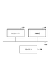
- FIG. 1 is a diagram showing a configuration of an imaging system (monitoring system) of the present embodiment.
- the imaging system (monitoring system) includes a camera server 100, a client 120, and an imaging device 140.
- the camera server 100, the client 120, and the imaging device 140 are connected to each other via the network 130.
- the camera server 100 can distribute the image acquired from the imaging device 140 via the network 130.
- the client 120 can access the camera server 100 and control image quality parameters such as pan / tilt / zoom, focus, and exposure while acquiring images, and can perform preset setting.
- image quality parameters such as pan / tilt / zoom, focus, and exposure while acquiring images, and can perform preset setting.
- one camera server is used for the sake of simplification, but two or more camera servers may be used.
- the network 130 can be composed of a plurality of routers, switches, cables, and the like that satisfy a communication standard such as Ethernet (registered trademark).
- a communication standard such as Ethernet (registered trademark).
- the communication standard, scale, and configuration of the network 130 are not limited as long as communication between the camera server 100 and the client 120 can be performed without any problem.
- the network 130 includes the Internet, a LAN (Local Area Network), a WAN (Wide Area Network), and the like.
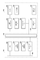
- FIG. 3 is a diagram illustrating a hardware configuration of the camera server 100 and the imaging device 140.
- the camera server 100 includes a CPU (Central Processing Unit) 300, a primary storage device 310, a secondary storage device 320, and a network I / F 305.
- the CPU 300, the primary storage device 310, the secondary storage device 320, and the network I / F (Interface) 305 are connected to the internal bus 302 and can perform data communication with each other.
- the primary storage device 310 is a high-speed writable storage device represented by, for example, a RAM (Random Access Memory), and is loaded with an OS (Operating System), various processing programs, and various data. It can also be used as a work area.
- OS Operating System
- the secondary storage device 320 is a non-volatile storage device represented by a flexible disk device (FDD), a hard disk device (HDD), a flash memory, a CD-ROM drive, etc., and the OS, various programs, and various data are persistent. In addition to being used as a general storage area, it can also be used as a storage area for various short-term data.
- the network I / F 305 functions as a communication unit for connecting to the network 130, and realizes communication with the imaging device 140, the client 120, and the like via a communication medium such as Ethernet (registered trademark).
- an image capture I / F 330, a pan head control I / F 340, a network I / F 360, and an audio input I / F 390 are connected to each other via an internal bus 303.
- the image capture I / F 330 is connected to an image sensor 370 configured by, for example, a CCD or CMOS that functions as an imaging unit.
- the image data acquired from the image sensor 370 via the image capture I / F 330 is processed according to the image quality parameter, converted and compressed into a predetermined format, transferred to the camera server 100 via the network 130, and a primary storage device. Stored in 310.
- the lens / head 380 is connected to the pan head control I / F 340 that controls the change of the photographing position and the photographing angle of view, and the photographing position and the photographing angle of view are changed by controlling the pan / tilt / zoom mechanism.
- the network I / F 360 functions as a communication unit for connecting to the network 130 and realizes communication with the camera server 100, the client 120, and the like via a communication medium such as Ethernet (registered trademark).
- the sound data collected from the sound input device 391 (sound collecting unit) such as a microphone is input to the sound input I / F 390, and the sound input I / F 390 converts the input sound data into digital data.
- the converted audio data is transferred to the camera server 100 via the network 130 and stored in the primary storage device 310.
- control device 200 is configured inside the camera server 100 as an example.
- the gist of the present invention is not limited to this example, and the control device 200 is, for example, a camera.
- the server 100, the client 120, and the imaging device 140 can be arranged inside.
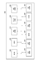
- FIG. 2 is a diagram illustrating a functional configuration of the control device 200.
- an OS which is a basic program for controlling the entire apparatus, and various processing programs are loaded in the storage unit 210
- each functional configuration is realized by executing the OS and the various processing programs by the CPU.
- the imaging processing unit 215 acquires image data captured by the image sensor 370 of the imaging device 140 via the image capture I / F 330, and performs image processing and encoding processing according to the image quality parameter set from the preset control unit 220. I do.
- the preset control unit 220 controls the shooting position via the pan head control I / F 340 in accordance with the preset position, preset tour setting, or preset movement setting by event under the control of the control unit 205.
- the lens / head 380 for changing the shooting angle of view and the pan / tilt / zoom positions are controlled.
- the preset control unit 220 sets image quality parameters such as focus, exposure, white balance, day / night, smart shade correction, noise reduction, sharpness, and color density stored as a preset in the imaging processing unit 215.
- the communication processing unit 225 transmits image data stored in the primary storage unit 113 to various clients via the network 130 in response to requests from various clients. Further, the communication processing unit 225 transfers preset positions and preset patrol settings sent from various clients, preset movement settings by events, pan / tilt / zoom positions and image quality parameters to the preset control unit 220, and also receives the received presets. Settings, preset tour settings, and the like are stored in the secondary storage device 320.
- the voice processing unit 230 acquires the voice data collected from the voice input device 391 and compares it with the threshold value stored in the secondary storage device 320 of the camera server 100. If the acquired audio data is greater than or equal to the threshold value by comparing the audio data with the threshold value, the audio processing unit 230 notifies the preset control unit 220 of a comparison result indicating that the acquired audio data is greater than or equal to the threshold value. By notifying the preset control unit 220 of the comparison result, preset control at the time of sound volume detection is executed. Further, the sound processing unit 230 manages the setting and state of the sound volume detection by holding the sound volume detection setting flag and the sound volume detection state flag in the storage unit 210 or the primary storage device 310 based on the acquired sound data. To do.
- the cooperation between the processing units uses functions provided by the OS as necessary.
- the detection unit 240 detects the volume of sound collected by a sound input device 391 (sound collection unit) such as a microphone.
- the control unit 205 performs first control to change the angle of view in the image sensor 370 (imaging unit) so as to capture an image of a predetermined angle of view when the detection unit 240 detects a volume that is equal to or higher than the threshold, and designation
- an instruction for causing the image sensor 370 (imaging unit) to capture an image of the angle of view that has been input is input, it is possible to execute a second control that changes the angle of view in accordance with the instruction.
- control unit 205 prioritizes the second control over the first control when the volume detection state when the volume higher than the threshold is detected is not changed.
- control can be executed. For example, when the detection unit 240 detects a sound volume equal to or higher than a predetermined threshold, the control unit 205 prioritizes the first control over the second control in a state before the execution of the first control is completed. To do.
- the control unit 205 has not changed the volume detection state in which the detection unit 240 has detected a volume equal to or higher than the threshold before the first control is completed. In this case, the second control is prioritized over the first control.
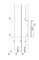
- FIG. 4 is a timing chart of the sound volume and sound processing unit 230.
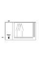
- FIG. 5 is a diagram illustrating an example of a UI screen on the client 120.
- FIG. 6 is a flowchart showing a flow of processing for performing the preset movement when the volume is detected.
- the horizontal axis represents time
- the vertical axis represents the state corresponding to each item of the volume 401, the volume detection state 402, and the volume detection setting 403 as ON / OFF.
- the state holding unit 255 holds the volume detection state (ON / OFF) of the detection unit 240 based on the detection result of the detection unit 240.
- the detection setting unit 245 performs a valid setting for executing the sound volume detection by the detection unit 240 or an invalid setting for not performing the sound volume detection by the detection unit 240.
- the volume 401 represents the state of the volume rang around the camera server 100. The state where the volume is less than the threshold for detecting the volume is turned off, and the state where the volume is greater than or equal to the threshold for detecting the volume is turned on.
- a sound volume detection state 402 held by the state holding unit 255 represents a sound volume detection state. ON indicates a state where the volume is being detected, and OFF indicates a state where the volume is not being detected.
- the sound processing unit 230 stores a flag indicating the sound volume detection state in the storage unit 210 or the primary storage device 310. The state of volume detection can be managed by a flag stored in the storage unit 210 or the primary storage device 310.
- the communication processing unit 225 can transmit a flag stored in the primary storage unit 113 to various clients via the network 130 in response to requests from various clients.
- the client 120 can control the display of the UI screen based on the flag acquired from the camera server 100.
- an identification display (icon 601) indicating whether or not the volume is being detected is displayed on the UI screen (600) of the client 120.
- the display of the identification display (icon 601) such as the display color and blinking, it is possible to identify and display whether the volume is being detected.
- the volume detection setting 403 set by the detection setting unit 245 indicates the state of volume detection setting. ON indicates that volume detection is performed (valid setting), and OFF indicates that volume detection is not performed even when a volume is received (invalid setting).
- the voice processing unit 230 stores a flag indicating the setting state of the volume detection in the storage unit 210 or the primary storage device 310. The state of the volume detection setting can be managed by the flag stored in the storage unit 210 or the primary storage device 310.
- T0 indicates the time in the initial state
- timing 404 indicates the timing at time T1
- timing 405 indicates the timing at time T2
- timing 406 indicates the timing at time T3.
- 4 shows that the imaging apparatus 140 is in the pan / tilt operation (PT operation) 407 from time T2 to time T3.
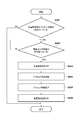
- step S ⁇ b> 601 the sound processing unit 230 acquires information from the storage unit 210 or the primary storage device 310 as to whether or not the preset movement at the time of detecting the volume is set.
- the preset movement at the time of detecting the volume is not set (S601-No)
- this process ends.
- the volume detection setting 403 is initially set to ON and the preset movement setting at the time of volume detection is also valid. If preset movement at the time of volume detection is set (S601-Yes), the process proceeds to step S602.
- step S602 the sound processing unit 230 determines whether or not a sound having a volume equal to or higher than a specific threshold is sounding around the camera server 100.
- step S602 when a sound having a volume higher than the threshold is not sounded (S602-No), the process stands by until a sound having a volume higher than the threshold is sounded.
- the volume 401 in the initial state, the volume 401 is in a state (OFF) below the threshold. Therefore, the sound volume detection state 402 is also a state where the sound volume is not detected (OFF).
- the sound processing unit 230 detects a sound volume equal to or higher than the threshold value at the timing 404 in FIG. 4, the sound volume detection state 402 is switched from OFF to ON. In FIG. 4, it is assumed that a sound equal to or higher than the threshold value is sounded at timing 404 and continues to sound after that.
- step S602 when a sound having a volume equal to or higher than the threshold value is sounded (S602-Yes), the voice processing unit 230 notifies the preset control unit 220 of a comparison result indicating that the acquired voice data is equal to or higher than the threshold value.
- the preset control unit 220 performs preset control at the time of volume detection under the control of the control unit 205, and moves the imaging device 140 to a predetermined position.
- the sound volume detection setting 403 is not changed at the timing 404 and remains ON.
- the audio processing unit 230 sets the volume detection setting 403 even if the volume is received from (ON) indicating that volume detection is to be performed. It switches to (OFF) which shows not performing a detection (S603). This is to prevent the built-in microphone from picking up pan and tilt operation sounds and causing the volume detection to malfunction.
- the setting of the volume detection state 402 is also switched from ON to OFF as the setting of the volume detection setting 403 is switched from ON to OFF.
- the sound processing unit 230 when starting the pan / tilt operation, causes the sound volume detection setting 403 to be turned on. Even when switched to OFF, the sound volume detection state 402 is controlled so as not to switch the state.
- the identification display (icon 601) on the UI screen (600) of the client 120 maintains the display indicating that the volume detection state is the ON state. It will be.
- step S604 under the control of the preset control unit 220, a pan / tilt operation (PT operation) is started at timing 405 (time T2), and the preset control unit 220 preset moves the imaging device 140 to a predetermined position. .
- PT operation pan / tilt operation
- the audio processing unit 230 When the pan / tilt operation ends at timing 406 (time T3) in FIG. 4 (S605), the audio processing unit 230 returns the setting of the volume detection setting 403 to ON in step S606.
- the sound processing unit 230 returns from the state (OFF) indicating that the sound volume detection is not performed even when the sound volume is received (ON) to the state (ON) indicating that the sound volume detection is performed, and the processing in FIG.
- the volume detection state 402 is also switched from OFF to ON at the timing when the volume detection setting 403 is switched from OFF to ON. Therefore, the voice processing unit 230 notifies the preset control unit 220 of the preset movement again, and the preset operation has started.
- the preset movement continues while the sound continues to sound, and manual camera control cannot be performed.
- the volume detection state 402 remains ON and the audio processing unit 230 notifies the preset control unit 220 of the preset movement. Not performed. For this reason, even in a situation where sound continues to sound around the camera server 100, the preset movement is not executed continuously after the preset movement is performed for the first time.
- the manual camera Control can be performed. According to the configuration of the present embodiment, it is possible to avoid malfunction due to volume detection and perform stable imaging control.
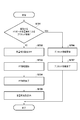
- FIG. 7 is a flowchart for explaining the flow of processing during pan / tilt operation.
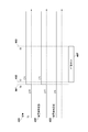
- 8 and 9 are timing charts of the sound volume and sound processing unit 230 in the second embodiment.
- the audio processing unit 230 determines whether the trigger for the pan / tilt operation is due to the preset movement when the volume is detected.
- the determination unit 250 moves the imaging unit to a preset position based on the detection result of the volume by the detection unit 240 and the setting of the detection setting unit 245, and performs the first control. It is determined whether or not to change the angle of view.
- FIG. 8 shows a timing chart of the sound volume and sound processing unit when the pan / tilt operation trigger is other than sound volume detection.
- the horizontal axis represents time
- the vertical axis represents the state corresponding to each item of the volume 401, the volume detection state 402, and the volume detection setting 403. / OFF.
- timing 801 indicates the timing at time T4
- timing 802 indicates the timing at time T5.
- the conditions for pan / tilt operation that are not preset movements based on volume detection are the following three cases.
- the volume detection setting 403 is in a state (ON) indicating that volume detection is performed, and the volume 401 around the camera server 100 is in a state below the threshold (OFF).
- the second case is a case where the sound volume detection setting 403 is in a state (OFF) indicating that sound volume detection is not performed even if a sound volume is received from the beginning.
- the third case is both cases (when the volume detection setting 403 is OFF from the beginning and the volume 401 around the camera server 100 is below the threshold (OFF)).
- the sound volume detection setting 403 is ON indicating that sound volume detection is performed, but the sound volume 401 is in a state indicating a state below the threshold value.
- the case of (OFF) is shown.
- step S701 if the event that triggers the pan / tilt operation is not a preset movement at the time of volume detection (S701-No), the process proceeds to step S702.
- the detection setting unit 245 of the control device 200 performs invalid setting (OFF) in which the volume detection is not performed when the angle of view is changed by the first control without detecting the volume, and the detection setting unit 245 When the change of the angle of view by the first control is completed, the effective setting for executing the sound volume detection is set (ON).
- the state holding unit 255 holds the volume detection state (in FIG. 8, holds the OFF state).
- step S702 the audio processing unit 230 receives the volume from the volume detection setting 403 (ON) indicating that the volume detection is to be performed before starting the pan / tilt operation at the timing 801 (time T4). Is also switched to (OFF) indicating that volume detection is not performed.
- the event that triggers step S702 includes, for example, angle of view control from the client 120.
- step S ⁇ b> 703 the change control unit 235 controls the operation of the lens / head 380 via the head control I / F 340 under the control of the control unit 205.
- a pan / tilt operation PT operation
- the sound volume detection does not malfunction because the sound volume detection setting 403 is OFF.
- step S704 the pan / tilt movement ends at timing 802 (time T5) after timing 801 (time T4).
- step S705 the sound processing unit 230 returns the sound volume detection setting 403 from (OFF) indicating that sound volume detection is not performed even when the sound volume is received to (ON) indicating that sound volume detection is performed, This process ends.
- the sound processing unit 230 since the sound volume 401 is in a state (OFF) indicating a state below the threshold, the sound processing unit 230 does not detect the sound volume. Therefore, the preset movement is not executed again continuously.
- the state where the volume 401 is less than the threshold (OFF) is exemplified. However, when the setting of the volume detection setting 403 is OFF, the sound processing unit 230 does not always detect the volume. Preset movement is not executed.
- step S701 determines whether the pan / tilt operation trigger is a preset movement at the time of volume detection (S701-Yes).
- the process proceeds to step S706.
- the detection setting unit 245 starts the change of the angle of view by the first control and ends the change of the angle of view by the first control.
- the effective setting for executing the volume detection is set (ON).
- the state holding unit 255 holds the volume detection state even when the detection unit 240 continues to detect a volume equal to or higher than the predetermined threshold (in the case of FIG. 9, the state is held ON). Specific processing will be described below.
- FIG. 9 is a timing chart of the sound volume and the sound processing unit when the pan / tilt operation trigger is sound volume detection.
- the horizontal axis represents time
- the vertical axis represents the state corresponding to each item of the volume 401, the volume detection state 402, and the volume detection setting 403. / OFF.
- timing 901 indicates the timing at time T6
- timing 902 indicates the timing at time T7
- timing 903 indicates the timing at time T8.
- the sound processing unit 230 detects a sound volume that is equal to or higher than the threshold value, so the sound volume detection state 402 switches from a sound volume not detected state (OFF) to a sound volume detected state (ON). . Since the volume detection state 402 has been switched from OFF to ON, the audio processing unit 230 notifies the preset control unit 220 of the preset movement.
- the audio processing unit 230 notifies the preset control unit 220 of a comparison result indicating that the acquired audio data is greater than or equal to the threshold value.
- the preset control unit 220 performs preset control at the time of volume detection under the control of the control unit 205, and moves the imaging device 140 to a predetermined position.
- the imaging apparatus 140 starts preset movement to a predetermined position.
- the sound processing unit 230 switches the sound volume detection setting 403 to OFF when starting the pan / tilt operation.
- the sound volume detection setting 403 is set. Is not switched off. Also, the sound volume detection state 402 remains in the ON state.
- the volume detection setting 403 remains ON, so the volume detection state 402 remains ON and remains unchanged. Since there is no change in the state of the sound volume detection state 402, the sound processing unit 230 does not notify the preset control unit 220 of the preset movement. Therefore, even in a situation where sound continues to sound around the camera server 100, the preset movement is not continuously executed after the preset movement is performed for the first time.
- the present invention supplies a program that realizes one or more functions of the above-described embodiments to a system or apparatus via a network or a storage medium, and one or more processors in a computer of the system or apparatus read and execute the program This process can be realized. It can also be realized by a circuit (for example, ASIC) that realizes one or more functions.
- a circuit for example, ASIC
- 215 Imaging processing unit
- 220 Preset control unit
- 225 Communication processing unit
- 230 Audio processing unit
Landscapes
- Engineering & Computer Science (AREA)
- Physics & Mathematics (AREA)
- Multimedia (AREA)
- General Physics & Mathematics (AREA)
- Signal Processing (AREA)
- Theoretical Computer Science (AREA)
- Health & Medical Sciences (AREA)
- General Health & Medical Sciences (AREA)
- Audiology, Speech & Language Pathology (AREA)
- General Engineering & Computer Science (AREA)
- Human Computer Interaction (AREA)
- Otolaryngology (AREA)
- Acoustics & Sound (AREA)
- Studio Devices (AREA)
- Accessories Of Cameras (AREA)
Abstract
制御装置は、撮像部に対応する音取得部によって取得される音の音量を検知する検知処理を行い、その音量が閾値以上の音量であるか判定し、その判定結果を出力する音量判定処理を実行する判定部と、判定結果が音量が閾値以上の音量であることを示す場合に撮像部における撮像方向を変更する第1の変更制御と、音量に係らずに撮像部における撮像方向を変更する第2の変更制御とを実行する変更制御部と、第2の変更制御を実行することに伴って第1の変更制御を行う状態とならないように、変更制御部によって第1の変更制御を実行している場合と、第2の変更制御を実行している場合とで、音量判定処理に係る制御を異ならせるよう制御する制御部とを有する。
Description
本発明は、制御装置、通信装置、制御方法及びプログラムに関するものである。
従来の監視システムで使用される監視カメラには、撮影可能視野の全体を固定で撮影する固定型タイプと、撮影可能視野内の複数の監視上重要な被写体を切り替えながら、若しくは巡回しながら撮影するパン・チルト・ズーム(PTZ)型タイプとがある。
PTZ型タイプでは、重要な被写体の望ましい撮影画角を予め登録することが行われ、撮影画角の登録は一般にプリセットと呼称されている。また、撮影可能視野内の特定の位置(プリセット位置)を登録しておき、ユーザーの操作に応じて登録されたプリセット位置への移動は、プリセット移動と呼称されている。例えば、特許文献1では、プリセット移動時に、パン・チルトは予め設定された位置に制御され、ズームとフォーカスはユーザーが別途制御する構成が開示されている。
監視目的などで運用される撮像装置では、撮像した映像の記録に加え、設置環境の音声状況の把握も重要である。特許文献2では、位置情報や音声情報を発信する専用機器(個別情報発信機)から情報を取得することで、撮影方向や撮影動作を制御する方法が開示されている。また、音量が一定以上の閾値を超えた場合に検知する音量検知機能を搭載した撮像装置も存在する。撮像装置によっては、サイズを小型にするため、音声状況の把握用の内蔵型マイクを搭載しているものがある。内蔵マイクを搭載した場合、パン、チルト動作音による音量検知の誤作動を防ぐため、パン、チルト動作中は音量検知を無効にする機能が知られている。
しかしながら、パン、チルト動作中に音量検知を無効にする機能を実行すると、次のような問題が発生する。前提として、音量検知時に特定の位置に移動するプリセット移動機能が設定されているとする。撮像装置の周囲で音が鳴り続けていると、音量検知の結果、撮像装置はプリセット移動する。パン、チルト移動中は音量検知を無効にしているが、プリセット移動が終わると音量検知は有効に設定される。プリセット移動後に、音量検知が有効になり、再度音が検知されると、プリセット移動が再度実行されてしまう。このため、音が鳴っている間、プリセット移動が実行され続けてしまい、カメラ制御を行えなくなってしまう場合が生じ得る。
本発明は、上記の課題を鑑みてなされたものであり、音量検知による誤動作を回避し、安定した撮像制御を行うことが可能な制御技術を提供する。
本発明の一態様による制御装置は以下の構成を備える。すなわち、制御装置は、
撮像手段に対応する音取得手段によって取得される音の音量を検知する検知処理を行い、その音量が閾値以上の音量であるか判定し、その判定結果を出力する音量判定処理を実行する判定手段と、
前記判定結果が前記音量が閾値以上の音量であることを示す場合に前記撮像手段における撮像方向を変更する第1の変更制御と、前記音量に係らずに前記撮像手段における撮像方向を変更する第2の変更制御とを実行する変更制御手段と、
前記第2の変更制御を実行することに伴って前記第1の変更制御を行う状態とならないように、前記変更制御手段によって前記第1の変更制御を実行している場合と、前記第2の変更制御を実行している場合とで、前記音量判定処理に係る制御を異ならせるよう制御する制御手段とを有することを特徴とする。
撮像手段に対応する音取得手段によって取得される音の音量を検知する検知処理を行い、その音量が閾値以上の音量であるか判定し、その判定結果を出力する音量判定処理を実行する判定手段と、
前記判定結果が前記音量が閾値以上の音量であることを示す場合に前記撮像手段における撮像方向を変更する第1の変更制御と、前記音量に係らずに前記撮像手段における撮像方向を変更する第2の変更制御とを実行する変更制御手段と、
前記第2の変更制御を実行することに伴って前記第1の変更制御を行う状態とならないように、前記変更制御手段によって前記第1の変更制御を実行している場合と、前記第2の変更制御を実行している場合とで、前記音量判定処理に係る制御を異ならせるよう制御する制御手段とを有することを特徴とする。
本発明によれば、音量検知による誤動作を回避し、安定した撮像制御を行うことが可能になる。
本発明のその他の特徴及び利点は、添付図面を参照とした以下の説明により明らかになるであろう。なお、添付図面においては、同じ若しくは同様の構成には、同じ参照番号を付す。
添付図面は明細書に含まれ、その一部を構成し、本発明の実施の形態を示し、その記述と共に本発明の原理を説明するために用いられる。
本実施形態におけるシステム構成図。
本実施形態の制御装置の機能構成を示す図。
本実施形態におけるカメラサーバーおよび撮像装置のハードウェア構成を示す図。
第1実施形態における音量及び音声処理部のタイミングチャート。
第1実施形態におけるクライアントのUI画面を例示する図。
第1実施形態における音量検知時にプリセット移動する動作を示すフローチャート。
第2実施形態におけるパン・チルト動作時のフローチャート。
第2実施形態におけるパン・チルト動作のトリガーが音量検知以外である場合の、音量および音声処理部のタイミングチャート。
2実施形態におけるパン・チルト動作のトリガーが音量検知である場合の、音量および音声処理部のタイミングチャート。
(第1実施形態)
以下、図面を参照して、本発明の実施形態を例示的に詳しく説明する。ただし、この実施形態に記載されている構成要素はあくまで例示であり、本発明の技術的範囲は、特許請求の範囲によって確定されるのであって、以下の個別の実施形態によって限定されるわけではない。
以下、図面を参照して、本発明の実施形態を例示的に詳しく説明する。ただし、この実施形態に記載されている構成要素はあくまで例示であり、本発明の技術的範囲は、特許請求の範囲によって確定されるのであって、以下の個別の実施形態によって限定されるわけではない。
図1は本実施形態の撮像システム(監視システム)の構成を示す図である。撮像システム(監視システム)は、カメラサーバー100、クライアント120および撮像装置140を有している。カメラサーバー100、クライアント120および撮像装置140はネットワーク130を介して相互に接続される。カメラサーバー100は撮像装置140から取得した画像を、ネットワーク130を介して配信することが可能である。クライアント120はカメラサーバー100にアクセスし、画像を取得しながら、パン・チルト・ズーム及びフォーカスや露出等の画質パラメータを制御して、プリセット設定することが可能である。尚、図1に示す撮像システム(監視システム)の構成として、説明の簡略化のためにカメラサーバーは1台としているが、2台以上であっても構わない。また、クライアント120以外にもカメラサーバー100にアクセスして画像の受信や蓄積を行う他のクライアントがあっても構わない。
ネットワーク130は、Ethernet(登録商標)等の通信規格を満足する複数のルータ、スイッチ、ケーブル等から構成することが可能である。本実施形態において、ネットワーク130は、カメラサーバー100、クライアント120間の通信が支障なく行えるものであればその通信規格、規模、構成を問わない。例えば、ネットワーク130は、インターネットやLAN(Local Area Network)やWAN(Wide Area Network)等を含む。
図3はカメラサーバー100および撮像装置140のハードウェア構成を例示する図である。カメラサーバー100は、CPU(Central Processing Unit)300、一次記憶装置310、二次記憶装置320およびネットワークI/F305を有する。CPU300、一次記憶装置310、二次記憶装置320およびネットワークI/F(インタフェース(Interface))305は、内部バス302に接続されており、相互にデータ通信が可能である。一次記憶装置310は、例えば、RAM(Random Access Memory)に代表される書き込み可能な高速の記憶装置で、OS(Operating System)や各種処理プログラム及び各種データがロードされ、またOSや各種処理プログラムの作業領域としても使用可能である。
二次記憶装置320は、フレキシブルディスク装置(FDD)やハードディスク装置(HDD)、フラッシュメモリ、CD-ROMドライブ等に代表される不揮発性を持った記憶装置で、OSや各種プログラム及び各種データの永続的な記憶領域として使用される他に、短期的な各種データの記憶領域としても使用可能である。ネットワークI/F305は、ネットワーク130と接続するための通信部として機能し、Ethernet(登録商標)等の通信媒体を介して、撮像装置140やクライアント120等との通信を実現する。
撮像装置140は、画像キャプチャI/F330、雲台制御I/F340、ネットワークI/F360、音声入力I/F390が内部バス303を介して相互に接続されている。
画像キャプチャI/F330には、例えば、撮像部として機能するCCDやCMOS等により構成される画像センサー370が接続されている。画像キャプチャI/F330を介して、画像センサー370から取得された画像データは、画質パラメータに従って処理され、所定のフォーマットに変換・圧縮され、ネットワーク130を介してカメラサーバー100に転送され、一次記憶装置310に保存される。
撮影位置や撮影画角の変更を制御する雲台制御I/F340には、レンズ/雲台380が接続され、パン・チルト・ズーム機構を制御して撮影位置や撮影画角を変更する。ネットワークI/F360は、ネットワーク130と接続するための通信部として機能し、Ethernet(登録商標)等の通信媒体を介して、カメラサーバー100やクライアント120等との通信を実現する。
マイク等の音声入力デバイス391(収音部)から収音された音声データは、音声入力I/F390に入力され、音声入力I/F390は入力された音声データをデジタルデータに変換処理をして、変換された音声データは、ネットワーク130を経由して、カメラサーバー100に転送され、一次記憶装置310に保存される。
次に、本実施形態に係る制御装置200の機能構成を説明する。以下の説明では、制御装置200は、カメラサーバー100の内部に構成されている場合を例として説明しているが、本発明の趣旨はこの例に限定されず、制御装置200は、例えば、カメラサーバー100、クライアント120、撮像装置140のいずれの内部に配置することが可能である。
図2は、制御装置200の機能構成を示す図である。記憶部210に装置全体を制御する基本プログラムであるOS、及び各種処理プログラムがロードされると、CPUによるOSおよび各種処理プログラムの実行により、各機能構成が実現される。撮像処理部215は、撮像装置140の画像センサー370で撮像された画像データを画像キャプチャI/F330を経由して取得し、プリセット制御部220から設定された画質パラメータに従って、画像処理と符号化処理を行う。プリセット制御部220は、制御部205の制御の下、クライアント120から予め設定されたプリセット位置やプリセット巡回設定、またはイベントによるプリセット移動設定に応じて、雲台制御I/F340を介して、撮影位置や撮影画角を変更するレンズ/雲台380を制御し、パン・チルト・ズーム位置を制御する。また、プリセット制御部220は、プリセットとして保存されているフォーカス、露出、ホワイトバランス、デイナイト、スマートシェード補正、ノイズリダクション、シャープネス、色の濃さ等の画質パラメータを、撮像処理部215に設定する。
通信処理部225は、各種クライアント等からのリクエストに応じて、一次記憶部113に保存されている画像データをネットワーク130を介して各種クライアントへ送信する。また、通信処理部225は、各種クライアントから送られるプリセット位置やプリセット巡回設定、またはイベントによるプリセット移動設定、パン・チルト・ズーム位置や画質パラメータをプリセット制御部220に転送し、また、受信したプリセット設定やプリセット巡回設定等を二次記憶装置320に保存する。
音声処理部230は、音声入力デバイス391から収音された音声データを取得し、カメラサーバー100の二次記憶装置320に保存されている閾値と比較する。音声データと閾値との比較により、取得した音声データが閾値以上だった場合、音声処理部230は、取得した音声データが閾値以上であることを示す比較結果をプリセット制御部220に通知する。比較結果をプリセット制御部220に通知することで、音量検知時のプリセット制御が実行される。また、音声処理部230は、取得した音声データに基づいて、音量検知設定のフラグ及び音量検知状態のフラグを記憶部210または一次記憶装置310に保持することで、音量検知の設定および状態を管理する。各処理部同士の連携は、必要に応じてOSが提供する機能を用いることとする。検知部240は、マイク等の音声入力デバイス391(収音部)によって収音された音の音量を検知する。制御部205は、検知部240によって閾値以上の音量が検知される場合に、所定の画角の画像を撮像するよう画像センサー370(撮像部)における画角を変更する第1の制御と、指定された画角の画像を画像センサー370(撮像部)に撮像させるための指示が入力されると、指示に従って画角を変更する第2の制御と、を実行することが可能である。
制御部205は、第1の制御の実行が終了する場合において、閾値以上の音量が検知されたときの音量検知の状態が変更されていない場合、第1の制御よりも第2の制御を優先して制御を実行することが可能である。例えば、検知部240によって所定の閾値以上の音量が検知される場合において、第1の制御の実行が終了する前の状態では、制御部205は、第2の制御よりも第1の制御を優先する。また、制御部205は、第1の制御の実行が終了する場合において、第1の制御を実行し終わる前から検知部240によって閾値以上の音量が検知された音量検知の状態が変更されていない場合、第1の制御よりも第2の制御を優先する。
次に、図4~図6を参照して、音量検知時にプリセット移動する処理の流れを説明する。図4は、音量および音声処理部230のタイミングチャートである。図5はクライアント120上のUI画面の一例を示す図である。図6は、音量検知時にプリセット移動する処理の流れを示すフローチャートである。
まず、図4のタイミングチャートについて説明する。図4のタイミングチャートにおいて、横軸は時間を表しており、縦軸は、音量401、音量検知状態402、音量検知設定403の各項目に対応した状態をON/OFFで表している。図2に示す機能構成において、状態保持部255は、検知部240の検知結果に基づいて、検知部240の音量検知の状態(ON・OFF)を保持する。検知設定部245は、検知部240による音量検知を実行する有効設定、または、検知部240による音量検知を実行しない無効設定を行う。
音量401はカメラサーバー100の周囲で鳴った音量の状態を表している。音量の大きさが、音量検知用の閾値未満の状態をOFFとし、音量検知用の閾値以上の状態をONとする。状態保持部255により保持される音量検知状態402は、音量検知の状態を表している。ONは音量検知中の状態を示し、OFFは音量検知していない状態を示している。音声処理部230は、音量検知の状態を示すフラグを記憶部210または一次記憶装置310に保存する。記憶部210または一次記憶装置310に保存したフラグにより、音量検知の状態を管理することが可能である。通信処理部225は、例えば、各種クライアントからのリクエストに応じて、一次記憶部113に保存されているフラグを、ネットワーク130を介して各種クライアントへ送信することが可能である。クライアント120は、例えば、カメラサーバー100から取得したフラグに基づいて、UI画面の表示を制御することが可能である。例えば、図6に示すように、クライアント120のUI画面(600)には、音量検知中か否かを示す識別表示(アイコン601)が表示される。識別表示(アイコン601)の表示色、点滅などの表示形態を表示制御することにより、音量検知中か否かを識別表示することが可能である。
説明を図4に戻し、検知設定部245により設定される音量検知設定403は、音量検知の設定の状態を示している。ONは音量検知を実行することを示し(有効設定)、OFFは、音量を受信しても音量検知を実行しないことを示す(無効設定)。音声処理部230は、音量検知の設定の状態を示すフラグを記憶部210または一次記憶装置310に保存する。記憶部210または一次記憶装置310に保存したフラグにより、音量検知の設定の状態を管理することが可能である。
図4において、T0は初期状態の時刻を示し、タイミング404は、時刻T1におけるタイミングを示し、タイミング405は、時刻T2におけるタイミングを示し、タイミング406は、時刻T3におけるタイミングを示している。図4において、時刻T2から時刻T3の間、撮像装置140がパン・チルト動作中(PT動作中)407であることを示している。
次に、図6のフローチャートにより、音量検知時にプリセット移動する処理の流れを説明する。まず、ステップS601において、音声処理部230は、音量検知時のプリセット移動が設定されているかどうかの情報を記憶部210または一次記憶装置310から取得する。音量検知時のプリセット移動が設定されていない場合(S601-No)、本処理は終了する。図4においては、最初、音量検知設定403がONに設定されており、音量検知時のプリセット移動の設定も有効になっているものとする。音量検知時のプリセット移動が設定されている場合(S601-Yes)、処理はステップS602に進められる。
ステップS602において、音声処理部230は、カメラサーバー100の周囲で特定の閾値以上の音量の音が鳴っているかどうかを判定する。ステップS602において、閾値以上の音量の音が鳴っていない場合(S602-No)、閾値以上の音量の音が鳴るまで待機状態となる。図4においては、初期状態において、音量401は閾値未満の状態(OFF)である。そのため、音量検知状態402も音量検知していない状態(OFF)である。
図4のタイミング404において、音声処理部230が閾値以上の音量を検知すると、音量検知状態402はOFFからONに切り替わる。図4において、タイミング404において閾値以上の音声が鳴り、その後も鳴り続けているものとする。
ステップS602において、閾値以上の音量の音が鳴った場合(S602-Yes)、音声処理部230は、取得した音声データが閾値以上であることを示す比較結果をプリセット制御部220に通知することで、プリセット制御部220は、制御部205の制御の下、音量検知時のプリセット制御を実行し、撮像装置140を所定の位置へプリセット移動させる。音量検知設定403については、タイミング404では変化がなくONのままである。
続いて、タイミング404(時刻T1)後のタイミング405(時刻T2)において、音声処理部230は、音量検知設定403を、音量検知を実行することを示す(ON)から音量を受信しても音量検知を実行しないことを示す(OFF)に切り替える(S603)。これは、内蔵マイクがパン、チルト動作音を収音し、音量検知が誤作動することを防ぐためである。従来の構成では、タイミング405において、音量検知設定403の設定がONからOFFに切り替わるのに合わせて音量検知状態402の設定もONからOFFに切り替わる。しかし、音が鳴っている間、カメラ制御を行えなくなってしまう問題を回避するため、本実施形態では、パン・チルト動作を開始する際に、音声処理部230は、音量検知設定403がONからOFFに切り替わっても、音量検知状態402は状態を切り替えないように制御する。図4の場合、パン・チルト動作中(PT動作中407)、クライアント120のUI画面(600)における識別表示(アイコン601)は、音量検知状態がON状態であることを示す表示が維持されることになる。
ステップS604において、プリセット制御部220の制御の下、タイミング405(時刻T2)において、パン・チルト動作(PT動作)が開始され、プリセット制御部220は、撮像装置140を所定の位置へプリセット移動させる。
図4のタイミング406(時刻T3)においてパン・チルト動作が終了すると(S605)、ステップS606において、音声処理部230は、音量検知設定403の設定をONに戻す。音声処理部230は、音量を受信しても音量検知を実行しないことを示す(OFF)から音量検知を実行することを示す状態(ON)に戻し、図6の処理は終了する。従来の構成では、音量検知設定403がOFFからONに切り替わるタイミングで、音量検知状態402もOFFからONに切り替わる。そのため、音声処理部230は、プリセット制御部220に再度プリセット移動の通知を行い、プリセット動作が開始してしまっていた。その後は、S602からS606を繰り返してしまうため、音が鳴り続けている間はプリセット移動し続けてしまい、手動によるカメラ制御ができなかった。本実施形態によれば、音量検知設定403がOFFからONに切り替わるタイミング406においても、音量検知状態402はONのまま変化がないため、音声処理部230はプリセット制御部220にプリセット移動の通知を行わない。そのため、カメラサーバー100の周囲で音声が鳴り続けている状況においても、最初にプリセット移動を行ったあとも続けてプリセット移動が実行されることがない。
このように音量検知状態402をON状態に保持することによって、音量検知時のプリセット移動を実行し終わった後に、所定の閾値以上の音量が検知され続けている場合であっても、手動によるカメラ制御を行うことが可能となる。本実施形態の構成によれば、音量検知による誤動作を回避し、安定した撮像制御を行うことが可能になる。
(第2実施形態)
次に、本発明の第2実施形態の処理を図7~図9により説明する。図7は、パン・チルト動作時の処理の流れを説明するフローチャートである。図8および図9は、第2実施形態における、音量および音声処理部230のタイミングチャートである。
次に、本発明の第2実施形態の処理を図7~図9により説明する。図7は、パン・チルト動作時の処理の流れを説明するフローチャートである。図8および図9は、第2実施形態における、音量および音声処理部230のタイミングチャートである。
S701において、音声処理部230は、パン・チルト動作のトリガーが音量検知時のプリセット移動によるものなのかどうかを判定する。図2の機能構成において、判定部250は、検知部240による音量の検知の結果、および検知設定部245の設定に基づいて、予め設定された位置に撮像部を移動させて第1の制御により画角を変更するか否かを判定する。
図8は、パン・チルト動作のトリガーが音量検知以外である場合の音量および音声処理部のタイミングチャートを示す。図8のタイミングチャートは、図4のタイミグチャートと同様に、横軸は時間を表しており、縦軸は、音量401、音量検知状態402、音量検知設定403の各項目に対応した状態をON/OFFで表している。図8において、タイミング801は、時刻T4におけるタイミングを示し、タイミング802は、時刻T5におけるタイミングを示している。
音量検知によるプリセット移動ではない、パン・チルト動作になる条件は、以下の3の場合がある。一つ目の場合は、音量検知設定403が音量検知を実行することを示す状態(ON)であり、且つ、カメラサーバー100周囲の音量401が閾値未満の状態(OFF)である場合である。二つ目の場合は、音量検知設定403が始めから、音量を受信しても音量検知を実行しないことを示す状態(OFF)である場合である。三つ目の場合は、その両方の場合(音量検知設定403が始めからOFFであり、かつ、カメラサーバー100周囲の音量401が閾値未満の状態(OFF)である場合)である。図8に示すタイミングチャートでは、1つ目の条件に対応する場合の例として、音量検知設定403は、音量検知を実行することを示すONであるが、音量401は閾値未満の状態を示す状態(OFF)である場合を示している。
ステップS701において、パン・チルト動作のトリガーとなるイベントが音量検知時のプリセット移動ではない場合(S701-No)、処理はステップS702に進められる。制御装置200の検知設定部245は、音量の検知によらずに第1の制御により画角を変更する場合に、音量検知を実行しない無効設定(OFF)とし、また、検知設定部245は、第1の制御による画角の変更が終了した場合に、音量検知を実行する有効設定とする(ON)。検知設定部245による音量検知の設定が無効設定(OFF)から有効設定(ON)になる場合に、状態保持部255は、音量検知の状態を保持する(図8ではOFFの状態を保持する)。以下、ステップS702以降の具体的な処理を説明する。ステップS702において、音声処理部230は、タイミング801(時刻T4)において、パン・チルト動作を開始する前に音量検知設定403を、音量検知を実行することを示す(ON)から音量を受信しても音量検知を実行しないことを示す(OFF)に切り替える。ステップS702のトリガーとなるイベントとしては、例えば、クライアント120からの画角制御などがある。
続いて、ステップS703において、変更制御部235は、制御部205の制御の下、雲台制御I/F340を介して、レンズ/雲台380の動作を制御する。この制御により、パン・チルト動作(PT動作)が開始する。パン・チルト動作中に内蔵マイクがパン、チルト動作音を収音したとしても、音量検知設定403がOFFのため、音量検知が誤作動することはない。
ステップS704において、タイミング801(時刻T4)より後のタイミング802(時刻T5)で、パン・チルト移動が終了する。そして、ステップS705において、音声処理部230は、音量検知設定403を、音量を受信しても音量検知を実行しないことを示す(OFF)から音量検知を実行することを示す(ON)に戻し、本処理は終了する。この際、音量401は閾値未満の状態を示す状態(OFF)であるため、音声処理部230が音量検知することがない。従って、続けてプリセット移動が再度実行されることはない。図8のタイミングチャートでは、音量401は閾値未満の状態を示す状態(OFF)を例示したが、音量検知設定403の設定がOFFの場合は、常に音声処理部230が音量検知することがないため、プリセット移動が実行されることがない。
一方、ステップS701の判定で、パン・チルト動作のトリガーが音量検知時のプリセット移動である場合(S701-Yes)、処理はステップS706に進められる。判定結果に基づいて、音量の検知により第1の制御により画角の制御を行う場合、検知設定部245は、第1の制御により画角の変更開始から第1の制御による画角の変更終了まで、音量検知を実行する有効設定とする(ON)。状態保持部255は、検知部240によって所定の閾値以上の音量が検知され続けている場合であっても、音量検知の状態を保持する(図9の場合ではON状態を保持する)。以下、具体的な処理を説明する。
図9は、パン・チルト動作のトリガーが音量検知である場合の、音量および音声処理部のタイミングチャートである。図9のタイミングチャートは、図4のタイミグチャートと同様に、横軸は時間を表しており、縦軸は、音量401、音量検知状態402、音量検知設定403の各項目に対応した状態をON/OFFで表している。図9において、タイミング901は、時刻T6におけるタイミングを示し、タイミング902は、時刻T7におけるタイミングを示し、タイミング903は、時刻T8におけるタイミングを示している。
図9のタイミングチャートにおいては、タイミング901(時刻T6)において閾値以上の音量が鳴り、その後も鳴り続けているものとする。また、タイミング901(時刻T6)において、音声処理部230は、閾値以上の音量を検知したため、音量検知状態402は、音量検知していない状態(OFF)から音量検知中の状態(ON)に切り替わる。音量検知状態402の状態がOFFからONに切り替わったため、音声処理部230は、プリセット制御部220にプリセット移動の通知を行う。そして、タイミング901(時刻T6)の後のタイミング902(時刻T7)において、音声処理部230は、取得した音声データが閾値以上であることを示す比較結果をプリセット制御部220に通知することで、プリセット制御部220は、制御部205の制御の下、音量検知時のプリセット制御を実行し、撮像装置140を所定の位置へプリセット移動させる。ステップS706において、撮像装置140は所定の位置へプリセット移動を開始する。第1実施形態では、タイミング405(時刻T2)において、音声処理部230はパン・チルト動作を開始する際に音量検知設定403をOFFに切り替えたが、本実施形態では、音量検知設定403の設定をOFFに切り替えない。また、音量検知状態402もONの状態のままとなる。
タイミング903(時刻T8)においてパン・チルト動作が終了しても(S707)、音量検知設定403はONのままであるため、音量検知状態402の状態はONのまま変化がない。音量検知状態402の状態に変化が無いため、音声処理部230はプリセット制御部220にプリセット移動の通知を行わない。そのため、カメラサーバー100の周囲で音声が鳴り続けている状況においても、最初にプリセット移動を行った後に、続けてプリセット移動が実行されることがない。
このように、パン・チルト動作のトリガーとなったイベントに応じて音量検知設定403の設定を切り替えることで、音量検知時のプリセット移動を実行し終わった後に、所定の閾値以上の音量が検知され続けている場合であっても、手動によるカメラ制御を優先することが可能となる。
(その他の実施形態)
本発明は、上述の実施形態の1以上の機能を実現するプログラムを、ネットワーク又は記憶媒体を介してシステム又は装置に供給し、そのシステム又は装置のコンピュータにおける1つ以上のプロセッサーがプログラムを読出し実行する処理でも実現可能である。また、1以上の機能を実現する回路(例えば、ASIC)によっても実現可能である。
本発明は、上述の実施形態の1以上の機能を実現するプログラムを、ネットワーク又は記憶媒体を介してシステム又は装置に供給し、そのシステム又は装置のコンピュータにおける1つ以上のプロセッサーがプログラムを読出し実行する処理でも実現可能である。また、1以上の機能を実現する回路(例えば、ASIC)によっても実現可能である。
本発明は上記実施の形態に制限されるものではなく、本発明の精神及び範囲から離脱することなく、様々な変更及び変形が可能である。従って、本発明の範囲を公にするために、以下の請求項を添付する。
本願は、2016年6月10日提出の日本国特許出願特願2016-116458を基礎として優先権を主張するものであり、その記載内容の全てを、ここに援用する。
215:撮像処理部、220:プリセット制御部、225:通信処理部、230:音声処理部
Claims (11)
- 撮像手段に対応する音取得手段によって取得される音の音量を検知する検知処理を行い、その音量が閾値以上の音量であるか判定し、その判定結果を出力する音量判定処理を実行する判定手段と、
前記判定結果が前記音量が閾値以上の音量であることを示す場合に前記撮像手段における撮像方向を変更する第1の変更制御と、前記音量に係らずに前記撮像手段における撮像方向を変更する第2の変更制御とを実行する変更制御手段と、
前記第2の変更制御を実行することに伴って前記第1の変更制御を行う状態とならないように、前記変更制御手段によって前記第1の変更制御を実行している場合と、前記第2の変更制御を実行している場合とで、前記音量判定処理に係る制御を異ならせるよう制御する制御手段と
を有することを特徴とする制御装置。 - 前記制御手段は、前記第2の変更制御を実行することに伴って前記第1の変更制御を行う状態とならないように、前記変更制御手段によって前記第1の変更制御を実行している場合に前記検知処理を無効とせず、前記第2の変更制御を実行している場合に前記検知処理を無効とする
ことを特徴とする請求項1に記載の制御装置。 - 前記制御手段は、
前記第2の変更制御を実行することに伴って前記第1の変更制御を行う状態とならないように、
前記変更制御手段によって前記第1の変更制御を実行している場合、及び、前記変更制御手段によって前記第2の変更制御を実行している場合に、前記検知処理を無効とし、
前記変更制御手段によって前記第1の変更制御を実行している場合は、前記検知処理を無効とした場合であっても、前記判定結果を、前記音量が閾値以上の音量であることに対応する判定結果とする
ことを特徴とする請求項1に記載の制御装置。 - 前記制御手段は、前記第1の変更制御の実行が終了する場合において、前記判定結果が前記音量が閾値以上の音量であることを示す場合、前記第1の変更制御よりも前記第2の変更制御を優先するよう前記音量判定処理に係る制御を異ならせる
ことを特徴とする請求項1に記載の制御装置。 - 前記制御手段は、前記第1の変更制御の実行が終了する前は、前記第2の変更制御よりも前記第1の変更制御を優先するよう前記音量判定処理に係る制御を異ならせる
ことを特徴とする請求項1に記載の制御装置。 - 前記制御手段は、
前記第1の変更制御の実行が終了する場合において、前記第1の変更制御を実行し終わる前から前記検知処理によって閾値以上の音量が検知された音量検知の状態が変化していない場合、前記第1の変更制御よりも前記第2の変更制御を優先するよう前記音量判定処理に係る制御を異ならせる
ことを特徴とする請求項1に記載の制御装置。 - 前記検知処理の検知結果に基づいて、前記判定結果を維持する維持手段を更に備え、
前記制御手段は、前記維持手段により維持されている前記判定結果に基づいて、前記第1の変更制御または前記第2の変更制御のいずれかを優先して実行する
ことを特徴とする請求項1に記載の制御装置。 - 前記検知処理を有効とする有効設定、または、前記検知処理を無効とする無効設定を行う設定手段を更に備え、
前記維持手段は、前記無効設定となる場合に前記判定結果を維持する
ことを特徴とする請求項7に記載の制御装置。 - 請求項1乃至8のいずれか1項に記載の制御装置を有することを特徴とする通信装置。
- 制御装置の制御方法であって、
撮像手段に対応する音取得手段によって取得される音の音量を検知する検知処理を行い、その音量が閾値以上の音量であるか判定し、その判定結果を出力する音量判定処理を実行する判定工程と、
前記判定結果が前記音量が閾値以上の音量であることを示す場合に前記撮像手段における撮像方向を変更する第1の変更制御と、前記音量に係らずに前記撮像手段における撮像方向を変更する第2の変更制御とを実行する変更制御工程と、
前記第2の変更制御を実行することに伴って前記第1の変更制御を行う状態とならないように、前記変更制御工程で前記第1の変更制御を実行している場合と、前記第2の変更制御を実行している場合とで、前記音量判定処理に係る制御を異ならせるよう制御する制御工程と
を有することを特徴とする制御方法。 - コンピュータを、制御装置の各手段として機能させるためのプログラムであって、前記制御装置が、
撮像手段に対応する音取得手段によって取得される音の音量を検知する検知処理を行い、その音量が閾値以上の音量であるか判定し、その判定結果を出力する音量判定処理を実行する判定手段と、
前記判定結果が前記音量が閾値以上の音量であることを示す場合に前記撮像手段における撮像方向を変更する第1の変更制御と、前記音量に係らずに前記撮像手段における撮像方向を変更する第2の変更制御とを実行する変更制御手段と、
前記第2の変更制御を実行することに伴って前記第1の変更制御を行う状態とならないように、前記変更制御手段によって前記第1の変更制御を実行している場合と、前記第2の変更制御を実行している場合とで、前記音量判定処理に係る制御を異ならせるよう制御する制御手段と
を有することを特徴とするプログラム。
Priority Applications (2)
| Application Number | Priority Date | Filing Date | Title |
|---|---|---|---|
| CN201780036028.2A CN109314747B (zh) | 2016-06-10 | 2017-04-18 | 控制设备、通信设备、控制方法和存储介质 |
| US16/205,818 US10863100B2 (en) | 2016-06-10 | 2018-11-30 | Control apparatus, communication apparatus, control method, and storage medium |
Applications Claiming Priority (2)
| Application Number | Priority Date | Filing Date | Title |
|---|---|---|---|
| JP2016-116458 | 2016-06-10 | ||
| JP2016116458A JP6771959B2 (ja) | 2016-06-10 | 2016-06-10 | 制御装置、通信装置、制御方法及びプログラム |
Related Child Applications (1)
| Application Number | Title | Priority Date | Filing Date |
|---|---|---|---|
| US16/205,818 Continuation US10863100B2 (en) | 2016-06-10 | 2018-11-30 | Control apparatus, communication apparatus, control method, and storage medium |
Publications (1)
| Publication Number | Publication Date |
|---|---|
| WO2017212796A1 true WO2017212796A1 (ja) | 2017-12-14 |
Family
ID=60577719
Family Applications (1)
| Application Number | Title | Priority Date | Filing Date |
|---|---|---|---|
| PCT/JP2017/015588 Ceased WO2017212796A1 (ja) | 2016-06-10 | 2017-04-18 | 制御装置、通信装置、制御方法及びプログラム |
Country Status (4)
| Country | Link |
|---|---|
| US (1) | US10863100B2 (ja) |
| JP (1) | JP6771959B2 (ja) |
| CN (1) | CN109314747B (ja) |
| WO (1) | WO2017212796A1 (ja) |
Cited By (1)
| Publication number | Priority date | Publication date | Assignee | Title |
|---|---|---|---|---|
| WO2020034207A1 (en) | 2018-08-17 | 2020-02-20 | SZ DJI Technology Co., Ltd. | Photographing control method and controller |
Citations (2)
| Publication number | Priority date | Publication date | Assignee | Title |
|---|---|---|---|---|
| JP2004336460A (ja) * | 2003-05-08 | 2004-11-25 | Minolta Co Ltd | 撮像装置およびその制御方法 |
| JP2008219227A (ja) * | 2007-03-01 | 2008-09-18 | Oki Electric Ind Co Ltd | 映像監視システムおよび映像監視方法 |
Family Cites Families (9)
| Publication number | Priority date | Publication date | Assignee | Title |
|---|---|---|---|---|
| JPH0983856A (ja) * | 1995-09-07 | 1997-03-28 | Nippon Telegr & Teleph Corp <Ntt> | インテリジェントカメラ装置 |
| JP2000092368A (ja) * | 1998-09-09 | 2000-03-31 | Canon Inc | カメラ制御装置及びコンピュータ読み取り可能な記憶媒体 |
| TWI235358B (en) * | 2003-11-21 | 2005-07-01 | Acer Inc | Interactive speech method and system thereof |
| JP2005277845A (ja) * | 2004-03-25 | 2005-10-06 | Sony Corp | 撮影制御装置 |
| JP2008124654A (ja) * | 2006-11-09 | 2008-05-29 | Fujinon Corp | リモコン雲台システム |
| JP5495612B2 (ja) * | 2008-04-23 | 2014-05-21 | キヤノン株式会社 | カメラ制御装置及び方法 |
| CN101610360A (zh) * | 2008-06-19 | 2009-12-23 | 鸿富锦精密工业(深圳)有限公司 | 自动追踪声源的摄像装置 |
| CN101771814A (zh) * | 2009-12-29 | 2010-07-07 | 天津市亚安科技电子有限公司 | 具有声音识别定位功能的云台摄像机 |
| CN103901782B (zh) * | 2012-12-25 | 2017-08-29 | 联想(北京)有限公司 | 一种声控方法、电子设备及声控装置 |
-
2016
- 2016-06-10 JP JP2016116458A patent/JP6771959B2/ja active Active
-
2017
- 2017-04-18 WO PCT/JP2017/015588 patent/WO2017212796A1/ja not_active Ceased
- 2017-04-18 CN CN201780036028.2A patent/CN109314747B/zh active Active
-
2018
- 2018-11-30 US US16/205,818 patent/US10863100B2/en active Active
Patent Citations (2)
| Publication number | Priority date | Publication date | Assignee | Title |
|---|---|---|---|---|
| JP2004336460A (ja) * | 2003-05-08 | 2004-11-25 | Minolta Co Ltd | 撮像装置およびその制御方法 |
| JP2008219227A (ja) * | 2007-03-01 | 2008-09-18 | Oki Electric Ind Co Ltd | 映像監視システムおよび映像監視方法 |
Cited By (3)
| Publication number | Priority date | Publication date | Assignee | Title |
|---|---|---|---|---|
| WO2020034207A1 (en) | 2018-08-17 | 2020-02-20 | SZ DJI Technology Co., Ltd. | Photographing control method and controller |
| EP3711284A4 (en) * | 2018-08-17 | 2020-12-16 | SZ DJI Technology Co., Ltd. | PHOTOGRAPHIC CONTROL PROCEDURE AND CONTROL |
| US11388343B2 (en) | 2018-08-17 | 2022-07-12 | SZ DJI Technology Co., Ltd. | Photographing control method and controller with target localization based on sound detectors |
Also Published As
| Publication number | Publication date |
|---|---|
| US10863100B2 (en) | 2020-12-08 |
| CN109314747A (zh) | 2019-02-05 |
| CN109314747B (zh) | 2021-07-23 |
| JP6771959B2 (ja) | 2020-10-21 |
| US20190098222A1 (en) | 2019-03-28 |
| JP2017220900A (ja) | 2017-12-14 |
Similar Documents
| Publication | Publication Date | Title |
|---|---|---|
| JP6786378B2 (ja) | 情報処理装置、情報処理方法及びプログラム | |
| JP5991514B2 (ja) | 撮像装置及び撮像システム | |
| KR102427095B1 (ko) | 화상 처리장치, 정보 처리장치, 정보 처리방법, 및 기록매체 | |
| JP2017212682A (ja) | 画像出力装置、画像出力方法及びプログラム | |
| JP2013013066A5 (ja) | ||
| US10462346B2 (en) | Control apparatus, control method, and recording medium | |
| JP5374080B2 (ja) | 撮影装置、その制御方法及びコンピュータプログラム | |
| JP5703788B2 (ja) | 撮像装置、画像処理装置、画像処理プログラム | |
| JP2016058984A (ja) | 監視システム、及びその制御方法 | |
| JP4898407B2 (ja) | 通信装置 | |
| JP6771959B2 (ja) | 制御装置、通信装置、制御方法及びプログラム | |
| JP7064546B2 (ja) | 制御装置、制御方法及びプログラム | |
| JP2016148832A (ja) | カメラ本体及び撮像装置 | |
| JP7746114B2 (ja) | 画像処理装置、画像処理方法、画像処理システム、およびプログラム | |
| JP6261191B2 (ja) | 表示制御装置、表示制御方法、プログラム | |
| JP2012242970A (ja) | 画像処理装置及びその制御方法 | |
| JP7471251B2 (ja) | 電動ズームカメラ及びその制御方法 | |
| JP6362090B2 (ja) | ネットワークカメラのプリセット位置の表示方法 | |
| JP7753057B2 (ja) | 撮像装置 | |
| JP2025182072A (ja) | 情報処理装置、撮像装置の制御方法及びプログラム | |
| JP2014007468A (ja) | 監視カメラシステム及び監視カメラ | |
| JP2012085125A (ja) | ネットワークカメラシステム、サーバ及びその制御方法、プログラム | |
| JP2008228039A (ja) | ネットワークカメラ装置及びその制御方法 | |
| JP6436823B2 (ja) | 撮像装置の制御方法、管理装置の制御方法、撮像装置及び管理装置 | |
| JP2007288265A (ja) | 映像通信装置、映像通信方法及びプログラム |
Legal Events
| Date | Code | Title | Description |
|---|---|---|---|
| 121 | Ep: the epo has been informed by wipo that ep was designated in this application |
Ref document number: 17809978 Country of ref document: EP Kind code of ref document: A1 |
|
| NENP | Non-entry into the national phase |
Ref country code: DE |
|
| 122 | Ep: pct application non-entry in european phase |
Ref document number: 17809978 Country of ref document: EP Kind code of ref document: A1 |