WO2017209495A1 - 리튬 이차전지용 분리막 및 이를 포함하는 리튬 이차전지 - Google Patents
리튬 이차전지용 분리막 및 이를 포함하는 리튬 이차전지 Download PDFInfo
- Publication number
- WO2017209495A1 WO2017209495A1 PCT/KR2017/005651 KR2017005651W WO2017209495A1 WO 2017209495 A1 WO2017209495 A1 WO 2017209495A1 KR 2017005651 W KR2017005651 W KR 2017005651W WO 2017209495 A1 WO2017209495 A1 WO 2017209495A1
- Authority
- WO
- WIPO (PCT)
- Prior art keywords
- lithium secondary
- secondary battery
- lithium
- gas
- separator
- Prior art date
Links
Images


Classifications
-
- C—CHEMISTRY; METALLURGY
- C08—ORGANIC MACROMOLECULAR COMPOUNDS; THEIR PREPARATION OR CHEMICAL WORKING-UP; COMPOSITIONS BASED THEREON
- C08J—WORKING-UP; GENERAL PROCESSES OF COMPOUNDING; AFTER-TREATMENT NOT COVERED BY SUBCLASSES C08B, C08C, C08F, C08G or C08H
- C08J7/00—Chemical treatment or coating of shaped articles made of macromolecular substances
- C08J7/12—Chemical modification
-
- H—ELECTRICITY
- H01—ELECTRIC ELEMENTS
- H01M—PROCESSES OR MEANS, e.g. BATTERIES, FOR THE DIRECT CONVERSION OF CHEMICAL ENERGY INTO ELECTRICAL ENERGY
- H01M50/00—Constructional details or processes of manufacture of the non-active parts of electrochemical cells other than fuel cells, e.g. hybrid cells
- H01M50/40—Separators; Membranes; Diaphragms; Spacing elements inside cells
- H01M50/409—Separators, membranes or diaphragms characterised by the material
-
- H—ELECTRICITY
- H01—ELECTRIC ELEMENTS
- H01M—PROCESSES OR MEANS, e.g. BATTERIES, FOR THE DIRECT CONVERSION OF CHEMICAL ENERGY INTO ELECTRICAL ENERGY
- H01M10/00—Secondary cells; Manufacture thereof
- H01M10/05—Accumulators with non-aqueous electrolyte
- H01M10/052—Li-accumulators
- H01M10/0525—Rocking-chair batteries, i.e. batteries with lithium insertion or intercalation in both electrodes; Lithium-ion batteries
-
- H—ELECTRICITY
- H01—ELECTRIC ELEMENTS
- H01M—PROCESSES OR MEANS, e.g. BATTERIES, FOR THE DIRECT CONVERSION OF CHEMICAL ENERGY INTO ELECTRICAL ENERGY
- H01M10/00—Secondary cells; Manufacture thereof
- H01M10/42—Methods or arrangements for servicing or maintenance of secondary cells or secondary half-cells
-
- H—ELECTRICITY
- H01—ELECTRIC ELEMENTS
- H01M—PROCESSES OR MEANS, e.g. BATTERIES, FOR THE DIRECT CONVERSION OF CHEMICAL ENERGY INTO ELECTRICAL ENERGY
- H01M50/00—Constructional details or processes of manufacture of the non-active parts of electrochemical cells other than fuel cells, e.g. hybrid cells
- H01M50/40—Separators; Membranes; Diaphragms; Spacing elements inside cells
- H01M50/489—Separators, membranes, diaphragms or spacing elements inside the cells, characterised by their physical properties, e.g. swelling degree, hydrophilicity or shut down properties
- H01M50/491—Porosity
-
- H—ELECTRICITY
- H01—ELECTRIC ELEMENTS
- H01M—PROCESSES OR MEANS, e.g. BATTERIES, FOR THE DIRECT CONVERSION OF CHEMICAL ENERGY INTO ELECTRICAL ENERGY
- H01M50/00—Constructional details or processes of manufacture of the non-active parts of electrochemical cells other than fuel cells, e.g. hybrid cells
- H01M50/40—Separators; Membranes; Diaphragms; Spacing elements inside cells
- H01M50/489—Separators, membranes, diaphragms or spacing elements inside the cells, characterised by their physical properties, e.g. swelling degree, hydrophilicity or shut down properties
-
- Y—GENERAL TAGGING OF NEW TECHNOLOGICAL DEVELOPMENTS; GENERAL TAGGING OF CROSS-SECTIONAL TECHNOLOGIES SPANNING OVER SEVERAL SECTIONS OF THE IPC; TECHNICAL SUBJECTS COVERED BY FORMER USPC CROSS-REFERENCE ART COLLECTIONS [XRACs] AND DIGESTS
- Y02—TECHNOLOGIES OR APPLICATIONS FOR MITIGATION OR ADAPTATION AGAINST CLIMATE CHANGE
- Y02E—REDUCTION OF GREENHOUSE GAS [GHG] EMISSIONS, RELATED TO ENERGY GENERATION, TRANSMISSION OR DISTRIBUTION
- Y02E60/00—Enabling technologies; Technologies with a potential or indirect contribution to GHG emissions mitigation
- Y02E60/10—Energy storage using batteries
Definitions
- the present invention relates to a lithium secondary battery separator and a lithium secondary battery comprising the same, and more particularly, to a lithium secondary battery separator and a lithium secondary battery including the same which can improve the life characteristics and safety of the lithium secondary battery.
- Such electric vehicles (EVs) and hybrid electric vehicles (HEVs) use nickel-metal hydride (Ni-MH) secondary batteries or lithium secondary batteries with high energy density, high discharge voltage, and output stability as power sources. Can be used for more than 10 years under severe conditions, with high energy density and high power output in a short time. Therefore, it has much better energy density, safety and longer life than conventional small lithium secondary batteries. Properties are inevitably required.
- Ni-MH nickel-metal hydride
- a lithium secondary battery is assembled by interposing a negative electrode and a cathode, and a separator interposed therebetween.
- Metal oxides such as LiCoO 2 , LiMnO 2 , LiMn 2 O 4, or LiCrO 2 are used as the positive electrode active material constituting the positive electrode of the lithium secondary battery, and metal lithium, graphite (graphite) ), Or carbon-based materials such as activated carbon, or materials such as silicon oxide (SiO x ) are used.
- lithium metal As a negative electrode of a lithium secondary battery, lithium metal, a carbon-based compound capable of intercalation and desorption of reversible lithium ions, and the like are used.
- the lithium metals as the charging and discharging cycles proceed, lithium atoms grow on the metal lithium surface to damage the separators, thereby causing the battery to break more frequently.
- the problem to be solved of the present invention is It is to provide a separator for a lithium secondary battery that can prevent the formation of dendrite on the negative electrode to improve the stability of the lithium secondary battery.
- Another object of the present invention is to provide a lithium secondary battery including the separator for a lithium secondary battery.
- Another object of the present invention is to provide a method of manufacturing the separator for a lithium secondary battery.
- a separator for a lithium secondary battery which is from 0.8 to 0.8: 0.2.
- It provides a lithium secondary battery comprising the separator for a lithium secondary battery.
- the separator for a lithium secondary battery according to the present invention includes a porous resin containing a polar functional group on the surface thereof, the polar functional group can suppress the formation of lithium on the surface of the negative electrode by forming a poorly soluble lithium salt layer on the surface of the negative electrode. In this case, lifespan characteristics and safety of the lithium secondary battery including the same may be improved.
- FIG. 1 is a view showing the step of treating the surface of the porous resin in N 2 gas, O 2 gas or a mixed gas prepared by mixing a mixture thereof, and F 2 gas to form a polar functional group on the surface.
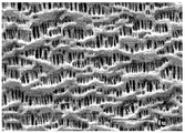
- FIG. 2 is a SEM photograph of the surface of the porous resin that may be included in the separator for a lithium secondary battery.
- Example 3 is a SEM photograph of the surface of the porous resin formed with a polar functional group included in the separator for a lithium secondary battery according to Example 1 of the present invention.
- Figure 6 is a view showing the results of measuring the concentration per area of the polar functional group of the porous separator in which the polar functional groups prepared in Examples 1 and 2, respectively.
- FIG. 7 is a view showing the results of measuring the total amount of the polar functional group of the porous separator in which the polar functional groups prepared in Examples 1 and 2 were introduced.
- reaction formulas (1) to (3) An example of the reaction at this time can be represented by the following reaction formulas (1) to (3).
- the layer of the poorly soluble lithium salt is formed on the negative electrode surface, it is possible to suppress the formation of lithium on the dendrite (dendrite) on the negative electrode surface.
- a lithium secondary battery including a separator for a lithium secondary battery according to an example of the present invention uses lithium metal as a negative electrode, the effective current density when lithium is precipitated at a defect point of the lithium metal.
- the formation of the dendrite can be suppressed.
- the polar functional group included in the porous resin may be 0.7 mol / cm 2 to 6 mol / cm 2 , specifically 1.8 mol / cm 2 to 3 mol / cm 2 , based on the surface area of the porous resin.
- the polar functional group included in the porous resin is 0.7 mol / cm 2 or more in the surface elements of the porous resin, the polar functional group is reduced and decomposed to an appropriate level on the surface of the cathode to form a layer of poorly soluble lithium salt on the lithium metal surface. can do.
- the polar functional group included in the porous resin exceeds 6 mol / cm 2 of the surface element of the porous resin, the layer of poorly soluble lithium salt formed on the surface of the negative electrode may be too thick to hinder the movement of lithium ions. have.
- the polar functional group may be present in an area of 0.01 ⁇ m to 1 ⁇ m toward the center from the surface of the porous resin, specifically, in an area of 0.01 ⁇ m to 0.5 ⁇ m, and more specifically in an area of 0.01 ⁇ m to 0.3 ⁇ m. May exist.
- the separator When the polar functional group is present only in an area of less than 0.01 ⁇ m toward the center from the surface of the porous resin, it is difficult for the separator to contain an appropriate amount of polar functional group, and the polar functional group is 1 ⁇ m toward the center from the surface of the porous resin. When present in excess of the area, it is difficult to form a poorly soluble lithium salt layer on the surface of the negative electrode smoothly.
- the total amount of the polar functional group included in the porous resin may be 0.1% to 2% by weight, specifically 0.2% to 0.8% by weight, based on 100% by weight of the total separator of the lithium secondary battery.
- the polar functional groups included in the porous resin When the total amount of the functional groups included in the porous resin is 0.1% by weight or more based on 100% by weight of the total separator for lithium secondary batteries, the polar functional groups are reduced and decomposed to an appropriate level on the surface of the lithium metal to be poorly soluble to the surface of the lithium metal.
- the layer of the lithium salt can be formed, and the total amount of the functional groups included in the porous resin is 2% by weight or less based on 100% by weight of the total lithium secondary battery separator, the layer of the poorly soluble lithium salt formed on the surface of the lithium metal is too thick. It is possible to prevent the interference of lithium ions.
- the porous resin is high density polyethylene, linear low density polyethylene, low density polyethylene, ultra high molecular weight polyethylene, polypropylene, polyethylene terephthalate, polybutylene terephthalate, polyester, polyacetal, polyamide, polycarbonate, polyimide, polyether ether ketone , Polyether sulfone, polyphenylene oxide, polyphenylene sulfide and polyethylene naphthalene may be formed using any one or a mixture of two or more thereof, and specifically, high density polyethylene, linear low density polyethylene, low density polyethylene , Polyolefin resins such as ultra high molecular weight polyethylene, polypropylene.
- Pore size and porosity of the porous resin is not particularly limited, porosity may be 5 to 95%, pore size (diameter) may be 0.01 to 10 ⁇ m. If the pore size and porosity are more than 0.01 ⁇ m and 5%, respectively, the movement of the electrolyte is smooth and the battery performance is not degraded. If the pore size and porosity are less than 10 ⁇ m and 95%, the mechanical properties can be properly maintained. Internal short circuit of the cathode can be prevented.
- the thickness of the porous resin is not particularly limited, but may be 1 to 300 ⁇ m, preferably 5 to 100 ⁇ m. When it is 1 ⁇ m or more, suitable mechanical properties may be exhibited, and when it is 300 ⁇ m or less, the separator including the porous resin may be prevented from acting as a resistance layer.
- the separator for a lithium secondary battery may be used to manufacture a lithium secondary battery, and thus the present invention provides a lithium secondary battery including the separator for a lithium secondary battery.
- -C-F contained in the surface of the porous resin included in the separator for lithium secondary battery according to the present invention; And at least one polar functional group selected from the group consisting of -C-OOH and -C O can be reductively decomposed during the charging of the lithium secondary battery to form a layer (inorganic protective film) of poorly soluble lithium salt on the surface of the negative electrode. .
- the poorly soluble lithium salt is lithium fluoride (LIF), lithium carbonate (Li 2 CO 3 ), lithium oxide (Li 2 O), lithium oxalate (Li 2 C 2 O 4 ), and lithium hydroxide (LiOH) It may be one or more selected from the group consisting of, specifically, may be lithium fluoride (LIF).
- the poorly soluble lithium salt layer may have a thickness of 0.001 to 0.5 ⁇ m, specifically 0.005 to 0.1 ⁇ m.
- the poorly soluble lithium salt layer When the thickness of the poorly soluble lithium salt layer is 0.001 ⁇ m or more, the poorly soluble lithium salt layer may properly act as an inorganic protective film on the surface of the lithium metal to suppress the formation of lithium dendrites, and When the thickness is 0.5 ⁇ m or less, no problem occurs in smooth movement and passage of lithium transfer.
- the separator for a lithium secondary battery according to the present invention comprises the steps of: (1) preparing a mixed gas by mixing N 2 gas, O 2 gas or a mixture thereof and F 2 gas; And (2) contacting the mixed gas with the porous resin to form a polar functional group on the surface of the porous resin.
- the N 2 gas, O 2 gas or the ratio of the pressure of the F 2 gas to the mixture thereof is 7.5: 2.5 to 9.4: can be 0.6 days, specifically 8: 2 to 9: 1, more specifically 8.5: 1.5 to 9: 1.
- the N 2 gas and O 2 gas is a pressure ratio of 1: 9 to 9: 1, specifically, a pressure ratio of 1.5: 8.5 to 8.5: 1.5, more specifically To a pressure ratio of 8: 2 to 7: 3. That is, the step of preparing the mixed gas of step (1) is a pressure ratio of N 2 gas and O 2 gas 1: 9 to 9: 1, specifically, a pressure ratio of 1.5: 8.5 to 8.5: 1.5, more specifically 8: It can be made by mixing the mixture and the F 2 gas mixture at a pressure ratio of 2 to 7: 3.
- the step of contacting the mixed gas of step (2) with the porous resin includes the step of contacting the mixed gas with respect to the porous resin.
- the step of contacting the mixed gas with the porous resin the porous resin is put in a container such as a pressure chamber, the mixed gas pressure of 1 KPa to 60 KPa, specifically 5 KPa to 50 KPa It may include the step of applying to the container to be a pressure of.
- the surface modification layer modified with this polar functional group can be formed uniformly.
- the surface of the porous resin may not be smoothly modified with a polar functional group, if the pressure of the mixed gas exceeds 60 KPa, process safety due to heat generation, combustion, fire, etc. May cause problems.
- the process of contacting the mixed gas with the porous resin may be made at a temperature of 0 to 100 °C, specifically 20 to 25 °C, contact time is 1 minute to 240 minutes, specifically 10 minutes to 30 minutes Can be.
- step (2) it may be further reacted with a gas containing H 2 O, specifically H 2 O in the gas phase.
- the reaction with the gas containing H 2 O may be made when the mixed gas prepared in the step (1) comprises O 2 gas.
- the mixed gas prepared in step (1) includes O 2 gas
- -CH bond on the surface of the porous resin forms peroxy radical (-OO.)
- FIG. 1 schematically illustrates an example of a process of forming a polar functional group on a surface by treating a porous resin surface with a mixed gas prepared by mixing a N 2 gas, an O 2 gas, or a mixture thereof and an F 2 gas. It is.
- (1) shows a form in which a polar functional group is formed on a surface of a porous resin containing polyolefin when treated with a mixed gas of F 2 gas and N 2 gas, and (2) includes polyolefin.
- a polar functional group is formed on the surface.
- the surface of the porous resin F 2 gas, N 2 gas, and O may be each modified by a second gas, which is formed because the polar functional group are each different depending on the type of gas, It is necessary to treat the porous resin by adjusting the partial pressures of the F 2 gas, the N 2 gas, and the O 2 gas in order to form the desired kind of polar functional group at a desired ratio.
- the lithium secondary battery may include a negative electrode, a separator interposed between the positive electrode and the negative electrode.
- the positive electrode can be prepared by conventional methods known in the art.
- a slurry may be prepared by mixing and stirring a solvent, a binder, a conductive material, and a dispersant in a positive electrode active material, and then applying (coating) to a current collector of a metal material, compressing, and drying the positive electrode to prepare a positive electrode.
- the current collector of the metal material is a metal having high conductivity, and is a metal to which the slurry of the positive electrode active material can easily adhere, and is particularly limited as long as it has high conductivity without causing chemical change in the battery in the voltage range of the battery.
- surface treated with carbon, nickel, titanium, silver, or the like on the surface of stainless steel, aluminum, nickel, titanium, calcined carbon, or aluminum or stainless steel may be used.
- fine unevenness may be formed on the surface of the current collector to increase the adhesion of the positive electrode active material.
- the current collector may be used in various forms such as a film, a sheet, a foil, a net, a porous body, a foam, a nonwoven fabric, and may have a thickness of 3 to 500 ⁇ m.
- the solvent for forming the positive electrode includes an organic solvent such as NMP (N-methyl pyrrolidone), DMF (dimethyl formamide), acetone, dimethyl acetamide or water, and these solvents alone or in combination of two or more. Can be mixed and used. The amount of the solvent used is sufficient to dissolve and disperse the positive electrode active material, the binder, and the conductive material in consideration of the coating thickness of the slurry and the production yield.
- NMP N-methyl pyrrolidone
- DMF dimethyl formamide
- acetone dimethyl acetamide or water
- the binder may be polyvinylidene fluoride-hexafluoropropylene copolymer (PVDF-co-HFP), polyvinylidene fluoride (polyvinylidenefluoride), polyacrylonitrile, polymethylmethacrylate, Polyvinyl alcohol, carboxymethyl cellulose (CMC), starch, hydroxypropyl cellulose, regenerated cellulose, polyvinylpyrrolidone, tetrafluoroethylene, polyethylene, polypropylene, polyacrylic acid, ethylene-propylene-diene monomer (EPDM), Sulfonated EPDM, styrene butadiene rubber (SBR), fluorine rubber, poly acrylic acid and polymers in which hydrogen thereof is replaced with Li, Na, or Ca, or Various kinds of binder polymers such as various copolymers can be used.
- PVDF-co-HFP polyvinylidene fluoride-hexafluoropropylene copolymer
- the conductive material is not particularly limited as long as it has conductivity without causing chemical change in the battery.
- Examples of the conductive material include graphite such as natural graphite and artificial graphite; Carbon blacks such as acetylene black, Ketjen black, channel black, farnes black, lamp black and thermal black; Conductive fibers such as carbon fibers and metal fibers; Conductive tubes such as carbon nanotubes; Metal powders such as fluorocarbon, aluminum and nickel powders; Conductive whiskers such as zinc oxide and potassium titanate; Conductive metal oxides such as titanium oxide; Conductive materials such as polyphenylene derivatives and the like can be used.
- the dispersant may be an aqueous dispersant or an organic dispersant such as N-methyl-2-pyrrolidone.
- the negative electrode may be prepared by conventional methods known in the art.
- the negative electrode may be formed of a carbon material, silicon-based, tin, or the like that may store and release lithium ions as a negative electrode active material, or may be made of lithium metal.
- the lithium metal when the negative electrode includes lithium metal, the lithium metal may be manufactured by a method of depositing a lithium metal foil or a current collector, applying liquid lithium, or attaching a lithium metal film.
- the negative electrode when the negative electrode includes a carbon material, a silicon-based or tin that can absorb and release lithium ions as a negative electrode active material, the negative electrode is a negative electrode active material slurry by mixing and stirring additives such as a negative electrode active material and a binder and a conductive material After the preparation, it can be prepared by applying it to a negative electrode current collector and drying and compressing it.
- both the low crystalline carbon and the high crystalline carbon may be used as the carbon material.
- Soft crystalline carbon and hard carbon are typical low crystalline carbon
- high crystalline carbon is natural graphite, kish graphite, pyrolytic carbon, liquid crystal pitch carbon fiber.
- high temperature calcined carbon such as mesophase pitch based carbon fiber, meso-carbon microbeads, mesophase pitches, and petroleum or coal tar pitch derived cokes.
- Examples of the silicon type include silicon, silicon oxide particles (SiO x , 0 ⁇ x ⁇ 2), Si-metal alloys, and an alloy of Si and silicon oxide particles (SiO x , 0 ⁇ x ⁇ 2).
- the solvent for forming the negative electrode includes an organic solvent such as NMP (N-methyl pyrrolidone), DMF (dimethyl formamide), acetone, dimethyl acetamide or water, and these solvents alone or in combination of two or more. Can be mixed and used. The amount of the solvent used is sufficient to dissolve and disperse the negative electrode active material, the binder, and the conductive material in consideration of the coating thickness of the slurry and the production yield.
- NMP N-methyl pyrrolidone
- DMF dimethyl formamide
- acetone dimethyl acetamide or water
- the binder may be used to bind the negative electrode active material particles to maintain the molded body, and is not particularly limited as long as it is a conventional binder used in preparing a slurry for the negative electrode active material.
- the non-aqueous binder may be polyvinyl alcohol, carboxymethyl cellulose, or hydroxy.
- Any one or a mixture of two or more selected from the group consisting of ronitrile-butadiene rubber, styrene-butadiene rubber and acrylic rubber can be used.
- Aqueous binders are economical and environmentally friendly compared to non-aqueous binders, are harmless to the health of workers, and have excellent binding effects compared to non-aqueous binders.
- Preferably styrene-butadiene rubber may be used.
- the conductive material is not particularly limited as long as it has conductivity without causing chemical change in the battery.
- Examples of the conductive material include graphite such as natural graphite and artificial graphite; Carbon blacks such as acetylene black, Ketjen black, channel black, furnace black, lamp black and summer black; Conductive fibers such as carbon fibers and metal fibers; Metal powders such as carbon fluoride powder, aluminum powder and nickel powder; Conductive whiskers such as zinc oxide and potassium titanate; Conductive metal oxides such as titanium oxide; Or conductive materials such as polyphenylene derivatives.
- the negative electrode current collector used for the negative electrode according to an embodiment of the present invention may have a thickness of 3 ⁇ m to 500 ⁇ m.
- the negative electrode current collector is not particularly limited as long as it has conductivity without causing chemical change in the battery.
- the negative electrode current collector may be formed on the surface of copper, gold, stainless steel, aluminum, nickel, titanium, calcined carbon, copper, or stainless steel. Surface-treated with carbon, nickel, titanium, silver and the like, aluminum-cadmium alloy and the like can be used.
- fine concavities and convexities may be formed on the surface to enhance the bonding strength of the negative electrode active material, and may be used in various forms such as films, sheets, foils, nets, porous bodies, foams, and nonwoven fabrics.
- organic solvent included in the electrolyte solution those conventionally used in the electrolyte for secondary batteries may be used without limitation, and typically propylene carbonate (PC), ethylene carbonate (ethylene carbonate, EC ), Diethyl carbonate (DEC), dimethyl carbonate (DMC), ethylmethyl carbonate (EMC), methylpropyl carbonate, dipropyl carbonate, dimethyl sulfoxide, acetonitrile, dimethoxyethane, diethoxyethane , Vinylene carbonate, sulfolane, gamma-butyrolactone, propylene sulfite, tetrahydrofuran, any one selected from the group consisting of, or mixtures of two or more thereof may be representatively used.
- PC propylene carbonate
- EC ethylene carbonate
- DEC Diethyl carbonate
- DMC dimethyl carbonate
- EMC ethylmethyl carbonate
- methylpropyl carbonate dipropyl carbon
- ethylene carbonate and propylene carbonate which are cyclic carbonates among the carbonate-based organic solvents, may be preferably used because they have high dielectric constants to dissociate lithium salts in the electrolyte, and may be preferably used in such cyclic carbonates.
- a low viscosity, low dielectric constant linear carbonate such as ethyl carbonate is mixed and used in an appropriate ratio, an electrolyte having high electrical conductivity can be prepared, and thus it can be used more preferably.
- the electrolyte solution stored according to the present invention may further include additives such as an overcharge inhibitor included in a conventional electrolyte solution.
- the external shape of the lithium secondary battery is not particularly limited, but may be cylindrical, square, pouch type or coin type using a can.
- the lithium secondary battery may be used in a battery cell used as a power source of a small device, and may be a unit cell of a battery module including a plurality of battery cells or a medium / large battery module used in a medium-large device.
- Preferred examples of the medium-to-large device include, but are not limited to, electric vehicles, hybrid electric vehicles, plug-in hybrid electric vehicles, and electric power storage systems.
- the porous separator was treated with a mixed gas in which F 2 , O 2 and N 2 gas were adjusted at a partial pressure ratio.
- All reaction lines, including reaction chambers or reaction tubes, were made of SUS-316, which is corrosion-resistant at room temperature in F 2 gas.
- a mixed gas of O 2 and N 2 are mixed and F 2 are similarly two to the composition of the atmosphere (air): was mixed in a ratio of 8, F 2 and, O 2 and N 2 1 the partial pressure of the gas mixture: 9
- the mixture was adjusted in a buffer tank to prepare a mixed treatment gas.
- a porous separator (polypropylene / polyethylene / polypropylene) was placed in the reaction chamber, and the mixed treatment gas was added thereto.
- the concentration of the mixed process gas was controlled by a gas valve between the buffer tank and the reaction chamber in a vacuum state to achieve a pressure condition of 30 KPa, and the reaction time was adjusted to 20 minutes.
- the surface of the porous separator was prepared in the same manner as in Example 1, except that the partial pressure of the F 2 , the O 2, and the N 2 mixed gas was adjusted to 2: 8, and mixed in a buffer tank to prepare a mixed process gas.
- a positive electrode mixture slurry was prepared by adding 94 wt% of LiCoO 2 as a cathode active material, 3 wt% of carbon black as a conductive agent, and 3 wt% of PVdF as a binder to N-methyl-2 pyrrolidone (NMP) as a solvent. .
- the positive electrode mixture slurry was applied to a thin film of aluminum (Al), which is a positive electrode current collector having a thickness of about 20 ⁇ m, and dried, followed by roll pressing to prepare a positive electrode.
- Example 2 After interposing the separator prepared in Example 1 (processing time 60 minutes) between the positive electrode and the negative electrode, which is Li metal, ethylene carbonate (EC) and diethyl carbonate (DEC) were mixed in a volume ratio of 50:50.
- a coin-type half cell was prepared by injecting an electrolyte solution in which 1 M LiPF 6 was dissolved in a solvent.
- a coin-type half cell was manufactured in the same manner as in Example 4, except that the separators prepared in Examples 2 and 3 were used instead of the separators prepared in Example 1 as separators.
- Example 1 the surface of the porous separator was prepared in the same manner, except that the partial pressure of the F 2 , the O 2, and the N 2 mixed gas was adjusted to 3: 7 and mixed in a buffer tank to prepare a mixed process gas.
- the surface of the porous separator was prepared in the same manner as in Example 2, except that the partial pressure of the F 2 , O 2, and N 2 mixed gas was adjusted to 0.5: 9.5, and mixed in a buffer tank to prepare a mixed process gas.
- Example 4 except for using a porous separator (polypropylene / polyethylene / polypropylene) without a functional group in place of the separator prepared in Example 1 as a separator, in the same manner as in Example 4 A coin-type half cell was prepared.
- a porous separator polypropylene / polyethylene / polypropylene
- Example 4 a coin-type half-cell was prepared in the same manner, except that the separators prepared in Comparative Examples 1 and 2 were used instead of the separators prepared in Example 1 as separators.
- ATR analysis was performed on the porous membranes in which the polar functional groups prepared in Examples 1 and 2 were introduced, respectively, and the results are shown in FIGS. 4 and 5, respectively, and the polarities prepared in Examples 1 and 2, respectively.
- the concentration per area of the polar functional group of the porous membrane into which the functional group was introduced was measured, and the results are shown in FIG. 6.
- the total amount of the polar functional group was increased as the concentration of the mixed gas and the treatment time increased, and manufactured in Examples 1 and 2, respectively.
- the total amount of the polar functional groups of the porous separator into which the polar functional groups were introduced was found to be 0.2 to 0.8 wt%.
- the coin-type half-cells prepared in Examples 4 to 6 and Comparative Examples 4 to 6, respectively were charged at 25 ° C. with a constant current (CC) of 0.8 C until they became 0.005 V, followed by a constant voltage of 0.005 V (CV). ), And the first charge was performed until the charge current became 0.005 C (cut-off current). Thereafter, the sample was left for 20 minutes and then discharged until it reached 1.5 V at a constant current (CC) of 0.8C. This was repeated for 1 to 70 cycles. Capacity retention after 70 cycles was derived by the following calculation.
- CC constant current
- CV constant voltage
- each of the coin-type half-cells prepared in Examples 4 to 6 shows a significantly better capacity retention after 70 cycles than the coin-type half-cells prepared in Comparative Examples 4 to 6, respectively. Able to know.
Landscapes
- Chemical & Material Sciences (AREA)
- Chemical Kinetics & Catalysis (AREA)
- General Chemical & Material Sciences (AREA)
- Electrochemistry (AREA)
- Engineering & Computer Science (AREA)
- Manufacturing & Machinery (AREA)
- Polymers & Plastics (AREA)
- Organic Chemistry (AREA)
- Medicinal Chemistry (AREA)
- Health & Medical Sciences (AREA)
- Materials Engineering (AREA)
- Secondary Cells (AREA)
- Cell Separators (AREA)
Abstract
본 발명은 표면에 -C-F; 및 -C-OOH 및 -C=O로 이루어진 군으로부터 선택된 1종 이상의 극성 관능기를 포함하는 다공성 수지를 포함하고, 상기 극성 관능기 중 -C-F에 대한 -C-OOH 및 -C=O의 몰비는 0.2:0.8 내지 0.8:0.2인 리튬 이차전지용 분리막 및 이의 제조방법에 관한 것이다.
Description
[관련출원과의 상호 인용]
본 출원은 2016년 05월 30일자 한국 특허 출원 제10-2016-0066720호 및 2017년 05월 30일자 한국 특허 출원 제10-2017-0066899호에 기초한 우선권의 이익을 주장하며, 해당 한국 특허 출원의 문헌에 개시된 모든 내용은 본 명세서의 일부로서 포함된다.
[기술분야]
본 발명은 리튬 이차전지용 분리막 및 이를 포함하는 리튬 이차전지에 관한 것으로, 보다 자세하게는 리튬 이차전지의 수명 특성 및 안전성을 향상시킬 수 있는 리튬 이차전지용 분리막 및 이를 포함하는 리튬 이차전지에 관한 것이다.
모바일 기기에 대한 기술 개발과 수요가 증가함에 따라 에너지원으로서의 이차전지에 대한 수요가 급격히 증가하고 있고, 그러한 이차전지 중에서도 높은 에너지 밀도와 작동 전위를 나타내고, 사이클 수명이 길며, 자기방전율이 낮은 리튬 이차전지가 상용화되어 널리 사용되고 있다.
또한, 최근에는 환경문제에 대한 관심이 커짐에 따라 대기오염의 주요 원인의 하나인 가솔린 차량, 디젤 차량 등 화석연료를 사용하는 차량을 대체할 수 있는 전기자동차(EV), 하이브리드 전기자동차(HEV) 등에 대한 연구가 많이 진행되고 있다.
이러한 전기자동차(EV), 하이브리드 전기자동차(HEV) 등은 동력원으로서 니켈 수소금속(Ni-MH) 이차전지 또는 높은 에너지 밀도, 높은 방전 전압 및 출력 안정성의 리튬 이차전지를 사용하고 있는데, 리튬 이차전지를 전기 자동차에 사용할 경우에는 높은 에너지 밀도와 단시간에 큰 출력을 발휘할 수 있는 특성과 더불어, 가혹한 조건 하에서 10년 이상 사용될 수 있어야 하므로, 기존의 소형 리튬 이차전지보다 월등히 우수한 에너지 밀도, 안전성 및 장기 수명 특성이 필연적으로 요구된다.
리튬 이차 전지는 일반적으로 음극(anode)과 양극(cathode), 이들 사이에 개재된 분리막(separator)을 개재시켜 조립하게 된다.
리튬 이차 전지의 양극을 구성하는 양극 활물질로서는 LiCoO2, LiMnO2, LiMn2O4 또는 LiCrO2와 같은 금속 산화물이 이용되고 있으며, 음극을 구성하는 음극 활물질로서는 금속 리튬(metal lithium), 흑연(graphite) 또는 활성탄(activated carbon) 등의 탄소계 물질(carbon based meterial), 또는 산화실리콘(SiOx) 등의 물질이 사용되고 있다.
리튬 이차 전지의 음극으로는 리튬 금속, 가역적인 리튬 이온의 삽입(intercalation) 및 탈리가 가능한 탄소계 화합물 등이 사용되고 있다. 이중 리튬 금속은 충전 및 방전 사이클이 진행됨에 따라 금속 리튬 표면에 리튬 원자가 성장하여 분리막을 손상시켜 전지를 파손시키는 현상이 더욱 빈번히 발생한다는 문제점이 있다.
따라서, 음극에서의 상기와 같은 문제점을 해결하기 위한 새로운 기술의 개발이 요구되고 있다.
본 발명의 해결하고자 하는 과제는 음극에서의 덴드라이트(dendrite) 상 리튬의 형성을 막아 리튬 이차전지의 안정성을 향상시킬 수 있는 리튬 이차전지용 분리막을 제공하는 것이다.
본 발명의 다른 해결하고자 하는 과제는 상기 리튬 이차전지용 분리막을 포함하는 리튬 이차전지를 제공하는 것이다.
본 발명의 또 다른 해결하고자 하는 과제는 상기 리튬 이차전지용 분리막의 제조방법을 제공하는 것이다.
상기 과제를 해결하기 위하여, 본 발명은
표면에 -C-F; 및 -C-OOH 및 -C=O로 이루어진 군으로부터 선택된 1종 이상의 극성 관능기를 포함하는 다공성 수지를 포함하고, 상기 극성 관능기 중 -C-F에 대한 -C-OOH 및 -C=O의 몰비는 0.2:0.8 내지 0.8:0.2인, 리튬 이차전지용 분리막을 제공한다.
또한, 본 발명은 상기 다른 과제를 해결하기 위하여,
상기 리튬 이차전지용 분리막을 포함하는 리튬 이차전지를 제공한다.
또한, 본 발명은 상기 또 다른 과제를 해결하기 위하여,
(1) N2 가스, O2 가스 또는 이들의 혼합물과 F2 가스를 혼합하여 혼합가스를 제조하는 단계; 및
(2) 상기 혼합가스를 다공성 수지와 접촉시켜 상기 다공성 수지의 표면에 극성 관능기를 형성시키는 단계를 포함하는, 리튬 이차전지용 분리막의 제조방법을 제공한다.
본 발명에 따른 리튬 이차전지용 분리막은 표면에 극성 관능기를 포함하는 다공성 수지를 포함하므로, 상기 극성 관능기가 음극 표면에 난용성 리튬염 층을 형성하여 음극 표면의 덴드라이트 상 리튬의 형성을 억제할 수 있어서, 이를 포함하는 리튬 이차전지의 수명 특성 및 안전성을 개선할 수 있다.
도 1은 다공성 수지 표면을 N2 가스, O2 가스 또는 이들의 혼합물과 F2 가스를 혼합하여 제조된 혼합가스로 처리하여 표면에 극성 관능기를 형성하는 과정을 모식적으로 나타낸 도면이다.
도 2는 리튬 이차전지용 분리막에 포함될 수 있는 다공성 수지 표면의 SEM 사진이다.
도 3은 본 발명의 실시예 1에 따른 리튬 이차전지용 분리막에 포함된 극성 관능기가 형성된 다공성 수지 표면의 SEM 사진이다.
도 4 및 5는 실시예 1 및 2에서 각각 제조된 다공성 분리막의 FT-ATR 결과를 나타낸 도면이다.
도 6은 실시예 1 및 2에서 각각 제조된 극성 관능기가 도입된 다공성 분리막의 극성 관능기의 면적당 농도를 측정한 결과를 나타낸 도면이다.
도 7은 실시예 1 및 2에서 각각 제조된 극성 관능기가 도입된 다공성 분리막의 극성 관능기의 총량을 측정한 결과를 나타낸 도면이다.
이하, 본 발명에 대한 이해를 돕기 위해 본 발명을 더욱 상세하게 설명한다.
본 명세서 및 청구범위에 사용된 용어나 단어는 통상적이거나 사전적인 의미로 한정해서 해석되어서는 아니 되며, 발명자는 그 자신의 발명을 가장 최선의 방법으로 설명하기 위해 용어의 개념을 적절하게 정의할 수 있다는 원칙에 입각하여 본 발명의 기술적 사상에 부합하는 의미와 개념으로 해석되어야만 한다.
본 발명에 따른 리튬 이차전지용 분리막은 표면에 -C-F; 및 -C-OOH 및 -C=O로 이루어진 군으로부터 선택된 1종 이상의 극성 관능기를 포함하는 다공성 수지를 포함하고, 상기 극성 관능기 중 -C-F에 대한 -C-OOH 및 -C=O의 몰비는 0.2:0.8 내지 0.8:0.2인 것이다.
본 발명에 따른 리튬 이차전지용 분리막은 상기 다공성 수지로 이루어진 것일 수 있으며, 상기 다공성 수지는 -C-F; 및 -C-OOH 및 -C=O로 이루어진 군으로부터 선택된 1종 이상의 극성 관능기를 포함하므로, 이를 포함하는 리튬 이차전지가 충전되는 과정에서, 상기 극성 관능기가 약 0.9~1.5 V vs. Li/Li+ 근방에서 환원분해(reduction or electrochemical carbonization) 되어 난용성 리튬염의 층(무기 보호 피막)을 형성할 수 있다.
이때의 반응의 일례는 하기 반응식 (1) 내지 (3)으로 나타낼 수 있다.
표면관능기와 리튬간의 환원반응
(1) mLi++ x(-C-F)@표면→(m-1)Li+ + x(-C-)@표면 + xLiF
(2) mLi+ + x(-C=O)@표면→(m-2)Li+ + x(-C-)@표면 + xLi2
(3) mLi+ + x(-C-00H)@표면→(m-3)Li+ + x(-C-)@표면 + xLi2O + xLiOH
상기 난용성 리튬염의 층이 음극 표면에 형성되어 있을 경우, 음극 표면에 덴드라이트(dendrite) 상의 리튬이 형성되는 것을 억제할 수 있다. 특히, 본 발명의 일례에 따른 리튬 이차전지용 분리막을 포함하는 리튬 이차전지가 리튬 금속을 음극으로 사용할 경우를 예로 들면, 상기 리튬 금속의 점 결함(defect point)에서 리튬이 석출될 경우에는 유효전류밀도의 집중에 의해 덴드라이트(dendrite) 상의 리튬이 주효하게 형성되는 문제점이 있지만, 리튬 금속의 표면에 상기와 같은 난용성 리튬염이 형성될 경우, 상기 덴드라이트의 형성이 억제될 수 있다.
상기 다공성 수지가 포함하는 극성 관능기는 상기 다공성 수지의 표면 면적에 대해 0.7 몰/cm2 내지 6 몰/cm2, 구체적으로 1.8 몰/cm2 내지 3 몰/cm2일 수 있다.
상기 다공성 수지가 포함하는 극성 관능기가 상기 다공성 수지의 표면 원소 중 0.7 몰/cm2 이상일 경우, 상기 극성 관능기가 음극 표면에서 적절한 정도로 환원 분해되어 리튬 금속 표면에 적절한 정도의 난용성 리튬염의 층을 형성할 수 있다. 한편, 상기 다공성 수지가 포함하는 극성 관능기가 상기 다공성 수지의 표면 원소 중 6 몰/cm2를 초과할 경우, 음극 표면에 형성되는 난용성 리튬염의 층이 지나치게 두꺼워져 리튬 이온의 이동을 방해할 수 있다.
상기 극성 관능기는 상기 다공성 수지의 표면으로부터 중심을 향하여 0.01 ㎛ 내지 1 ㎛의 영역에 존재할 수 있고, 구체적으로 0.01 ㎛ 내지 0.5 ㎛의 영역에 존재할 수 있으며, 더욱 구체적으로 0.01 ㎛ 내지 0.3 ㎛의 영역에 존재할 수 있다.
상기 극성 관능기가 상기 다공성 수지의 표면으로부터 중심을 향하여 0.01 ㎛ 미만인 영역에만 존재할 경우, 상기 분리막이 적절한 양의 극성 관능기를 포함하기 어려우며, 상기 극성 관능기가 상기 다공성 수지의 표면으로부터 중심을 향하여 1 ㎛를 초과하는 영역에 존재할 경우, 음극 표면에 원활히 난용성 리튬염 층을 형성하기 어렵다.
또한, 상기 다공성 수지가 포함하는 극성 관능기의 총량은 상기 리튬 이차전지용 분리막 총 100 중량%를 기준으로 0.1 중량% 내지 2 중량%, 구체적으로 0.2 중량% 내지 0.8 중량%일 수 있다.
상기 다공성 수지가 포함하는성 관능기의 총량이 리튬 이차전지용 분리막 총 100 중량%를 기준으로 0.1 중량% 이상일 경우, 상기 극성 관능기가 리튬 금속 표면에서 적절한 정도로 환원 분해되어 리튬 금속 표면에 적절한 정도의 난용성 리튬염의 층을 형성할 수 있고, 상기 다공성 수지가 포함하는 관능기의 총량이 리튬 이차전지용 분리막 총 100 중량%를 기준으로 2 중량% 이하일 경우, 리튬 금속 표면에 형성되는 난용성 리튬염의 층이 지나치게 두꺼워져 리튬 이온의 이동을 방해하게 되는 것을 방지할 수 있다.
상기 극성 관능기 중 -C-F에 대한 -C-OOH 및 -C=O의 몰비는 0.2:0.8 내지 0.8:0.2일 수 있고, 구체적으로 0.3:0.7 내지 0.7:0.3일 수 있으며, 더욱 구체적으로 0.4:0.6 내지 0.6:0.4일 수 있다.
상기 극성 관능기 중 -C-F 0.2 몰에 대해 -C-OOH 및 -C=O의 합계 몰 수가 0.8을 초과할 경우, LiF 리튬염이 충분히 형성되지 않는 문제가 있고, 상기 극성 관능기 중 -C-F 0.8 몰에 대해 -C-OOH 및 -C=O의 합계 몰 수가 0.2 미만일 경우, LiF 리튬염이 과도하게 형성되는 문제가 있다.
상기 다공성 수지는 고밀도 폴리에틸렌, 선형 저밀도 폴리에틸렌, 저밀도 폴리에틸렌, 초고분자량 폴리에틸렌, 폴리프로필렌, 폴리에틸렌테레프탈레이트, 폴리부틸렌테레프탈레이트, 폴리에스테르, 폴리아세탈, 폴리아미드, 폴리카보네이트, 폴리이미드, 폴리에테르에테르케톤, 폴리에테르설폰, 폴리페닐렌옥사이드, 폴리페닐렌설파이드 및 폴리에틸렌나프탈렌으로 이루어진 군으로부터 선택된 어느 하나 또는 이들 중 2종 이상의 혼합물을 이용하여 형성된 것일 수 있고, 구체적으로 고밀도 폴리에틸렌, 선형 저밀도 폴리에틸렌, 저밀도 폴리에틸렌, 초고분자량 폴리에틸렌, 폴리프로필렌과 같은 폴리올레핀 수지일 수 있다.
상기 다공성 수지의 기공 크기 및 기공도는 특별한 제한이 없으나, 기공도는 5 내지 95%일 수 있고, 기공 크기(직경)는 0.01 내지 10 ㎛일 수 있다. 기공 크기 및 기공도가 각각 0.01 ㎛ 및 5% 이상일 경우 전해액의 이동이 원활하여 전지 성능이 저하되지 않으며, 기공 크기 및 기공도가 10 ㎛ 및 95% 이하인 경우 기계적 물성을 적절히 유지할 수 있고, 양극과 음극의 내부 단락을 방지할 수 있다. 또한, 다공성 수지의 두께는 크게 제한이 없으나, 1 내지 300 ㎛일 수 있고, 바람직하게는 5 내지 100 ㎛일 수 있다. 1 ㎛ 이상일 경우 적절한 기계적 물성을 발휘할 수 있고, 300 ㎛ 이하일 경우, 상기 다공성 수지를 포함하는 분리막이 저항층으로 작용하는 것을 방지할 수 있다.
상기 리튬 이차전지용 분리막은 리튬 이차전지의 제조에 사용될 수 있으며, 따라서 본 발명은 상기 리튬 이차전지용 분리막을 포함하는 리튬 이차전지를 제공한다.
전술한 바와 같이, 본 발명에 따른 상기 리튬 이차전지용 분리막이 포함하는 다공성 수지의 표면에 포함된 -C-F; 및 -C-OOH 및 -C=O로 이루어진 군으로부터 선택된 1종 이상의 극성 관능기는 리튬 이차전지가 충전되는 과정에서 환원분해되어 음극 표면에 난용성 리튬염의 층(무기 보호 피막)을 형성할 수 있다.
상기 난용성 리튬염은 리튬플루오라이드(LIF), 리튬카보네이트(Li2CO3), 리튬옥사이드(Li2O), 리튬옥살레이트(Li2C2O4), 및 리튬하이드록사이드(LiOH)로 이루어진 군으로부터 선택된 1종 이상인 것일 수 있고, 구체적으로 리튬플루오라이드(LIF)일 수 있다.
상기 난용성 리튬염 층의 두께는 0.001 내지 0.5 ㎛일 수 있고, 구체적으로 0.005 내지 0.1 ㎛일 수 있다.
상기 난용성 리튬염 층의 두께가 0.001 ㎛ 이상일 경우, 상기 난용성 리튬염 층이 리튬 금속 표면에서 적절히 무기 보호 피막으로서 작용하여 리튬 덴드라이트의 형성을 억제할 수 있으며, 상기 난용성 리튬염 층의 두께가 0.5 ㎛ 이하일 경우, 리튬 이동의 원활한 이동 및 통과에 문제가 발생하지 않는다.
상기 본 발명에 따른 리튬 이차전지용 분리막은 (1) N2 가스, O2 가스 또는 이들의 혼합물과 F2 가스를 혼합하여 혼합가스를 제조하는 단계; 및 (2) 상기 혼합가스를 다공성 수지와 접촉시켜 상기 다공성 수지의 표면에 극성 관능기를 형성시키는 단계를 포함하는 방법에 의해 제조될 수 있다.
상기 단계 (1)의 혼합가스를 제조하는 단계에서, 상기 N2 가스, O2 가스 또는 이들의 혼합물에 대한 상기 F2 가스의 압력의 비는 7.5:2.5 내지 9.4:0.6일 수 있고, 구체적으로 8:2 내지 9:1, 더욱 구체적으로 8.5:1.5 내지 9:1일 수 있다.
상기 단계 (1)의 혼합가스를 제조하는 단계에서, 상기 N2 가스, O2 가스 또는 이들의 혼합물에 대해 상기 F2 가스를 7.5:2.5 내지 9.4:0.6의 압력비가 되도록 혼합할 경우, 상기 리튬 이차전지용 분리막이 포함하는 다공질 수지의 표면에 극성 관능기로서 -C-F가 적절한 양, 즉 -C-F에 대한 -C-OOH 및 -C=O의 몰비가 0.2:0.8 내지 0.8:0.2를 만족하도록 형성될 수 있다.
또한, 상기 단계 (1)의 혼합가스를 제조하는 단계에 있어서, 상기 N2 가스 및 O2 가스는 1:9 내지 9:1의 압력비, 구체적으로 1.5:8.5 내지 8.5:1.5의 압력비, 더욱 구체적으로 8:2 내지 7:3의 압력비로 혼합될 수 있다. 즉, 상기 단계 (1)의 혼합가스를 제조하는 단계는 N2 가스 및 O2 가스를 1:9 내지 9:1의 압력비, 구체적으로 1.5:8.5 내지 8.5:1.5의 압력비, 더욱 구체적으로 8:2 내지 7:3의 압력비로 혼합한 혼합물과 F2 가스를 혼합하여 이루어질 수 있다.
상기 N2 가스 1에 대해 O2 가스가 9를 초과하는 압력을 가질 경우, 발열, 연소, 화재 등에 따른 공정상의 안전성에 문제가 발생할 수 있다.
상기 단계 (2)의 혼합가스를 다공성 수지와 접촉시키는 과정은, 상기 다공성 수지에 대해 상기 혼합가스를 접촉시키는 과정을 포함한다. 본 발명의 일례에 있어서, 상기 혼합가스를 다공성 수지와 접촉시키는 과정은, 상기 다공성 수지를 압력 챔버 등의 용기에 넣고, 상기 혼합가스를 1 KPa 내지 60 KPa의 압력, 구체적으로 5 KPa 내지 50 KPa의 압력이 되도록 상기 용기에 가하는 과정을 포함할 수 있다.
상기 다공성 수지를 압력 챔버 등의 용기에 넣고 상기 혼합가스를 가할 경우, 상기 다공성 수지의 표면에 상기 혼합가스가 확산하여 반응이 이루어지며, 고체 표면에 대한 기체 확산에 의한 반응이므로, 다공성 수지의 표면이 극성 작용기로 개질된 표면 개질층이 균일하게 형성될 수 있다.
상기 혼합가스의 압력이 1 KPa 미만일 경우, 상기 다공성 수지의 표면이 극성 작용기로 원활히 개질되지 않을 수 있고, 상기 혼합가스의 압력이 60 KPa를 초과할 경우, 발열, 연소, 화재 등에 따른 공정상의 안전성에 문제가 발생할 수 있다.
상기 혼합가스를 다공성 수지와 접촉시키는 과정은, 0 내지 100 ℃의 온도, 구체적으로 20 내지 25 ℃의 온도에서 이루어질 수 있으며, 접촉시간은 1분 내지 240분, 구체적으로 10분 내지 30분 동안 이루어질 수 있다.
상기 혼합가스를 다공성 수지와 접촉시키는 과정이 0 내지 100 ℃의 온도를 벗어날 경우, 상기 다공성 분리막의 수축이 발생될 수 있고, 상기 접촉시간이 1분 미만일 경우 관능기의 형성량이 부족할 수 있고, 240분을 초과할 경우 과도한 -C-F가 형성될 수 있다.
상기 단계 (2) 이후 H2O를 포함하는 기체, 구체적으로 기체 상의 H2O와 추가로 반응하는 단계가 이루어질 수 있다.
특히, 상기 H2O를 포함하는 기체와의 반응은 상기 단계 (1)에서 제조되는 혼합가스가 O2 가스를 포함할 경우 이루어질 수 있다. 구체적으로. 상기 단계 (1)에서 제조되는 혼합가스가 O2 가스를 포함할 경우, 상기 다공성 수지 표면의 -C-H 결합이 상기 O2와의 반응을 통하여 퍼옥시 라디칼(-OOㆍ)을 형성하게 되므로, 상기 H2O 기체와의 반응을 통하여 이를 하이드록시 퍼옥사이드(-O-OH) 또는 카르보닐(-C=O)기로 변형하는 단계가 이루어질 수 있다.
도 1에는 다공성 수지 표면을 N2 가스, O2 가스 또는 이들의 혼합물과 F2 가스를 혼합하여 제조된 혼합가스로 처리하여 표면에 극성 관능기를 형성하는 과정의 일례를 모식적으로 나타낸 도면이 도시되어 있다.
도 1을 참조하면, (1)에는 폴리올레핀을 포함하는 다공성 수지를 F2가스와 N2 가스의 혼합가스로 처리하였을 때 표면에 극성 관능기가 형성되는 형태가 나타나 있고, (2)에는 폴리올레핀을 포함하는 다공성 수지를 F2가스와 O2 가스의 혼합가스로 처리하였을 때 표면에 극성 관능기가 형성되는 형태가 나타나 있다. 도 1에 나타낸 바와 같이, 다공성 수지의 표면의 -C-H는 F2 가스, N2 가스, 및 O2 가스에 의해 각각 개질될 수 있으며, 형성되는 극성 관능기는 가스의 종류에 따라 각각 차이가 있으므로, 목적하는 종류의 극성 관능기를 원하는 비율로 형성하기 위하여 F2 가스, N2 가스, 및 O2 가스의 분압을 조절하여 다공성 수지를 처리할 필요가 있다.
한편, 본 발명에 있어서, 상기 리튬 이차전지는 음극, 상기 양극과 음극 사이에 개재된 세퍼레이터를 포함하는 것일 수 있다.
상기 양극은 당 분야에 알려져 있는 통상적인 방법으로 제조할 수 있다. 예를 들면, 양극 활물질에 용매, 필요에 따라 바인더, 도전재, 분산제를 혼합 및 교반하여 슬러리를 제조한 후 이를 금속 재료의 집전체에 도포(코팅)하고 압축한 뒤 건조하여 양극을 제조할 수 있다.
상기 금속 재료의 집전체는 전도성이 높은 금속으로서, 상기 양극 활물질의 슬러리가 용이하게 접착할 수 있는 금속으로 전지의 전압 범위에서 당해 전지에 화학적 변화를 유발하지 않으면서 높은 도전성을 가지는 것이라면 특별히 제한되는 것은 아니며, 예컨대 스테인레스 스틸, 알루미늄, 니켈, 티탄, 소성 탄소, 또는 알루미늄이나 스테리인레스 스틸의 표면에 카본, 니켈, 티탄, 은 등으로 표면 처리한 것 등이 사용될 수 있다. 또한, 집전체 표면에 미세한 요철을 형성하여 양극 활물질의 접착력을 높일 수도 있다. 집전체는 필름, 시트, 호일, 네트, 다공질체, 발포체, 부직포체 등 다양한 형태로 사용 가능하며, 3 내지 500 ㎛의 두께를 갖는 것일 수 있다.
상기 양극 활물질은, 예컨대 리튬 코발트 산화물(LiCoO2); 리튬 니켈 산화물(LiNiO2); Li[NiaCobMncM1
d]O2(상기 식에서, M1은 Al, Ga 및 In으로 이루어진 군에서 선택되는 어느 하나 또는 이들 중 2종 이상의 원소이고, 0.3≤a<1.0, 0≤b≤0.5, 0≤c≤0.5, 0≤d≤0.1, a+b+c+d=1이다); Li(LieM2
f-e-f'M3
f')O2
-
gAg(상기 식에서, 0≤e≤0.2, 0.6≤f≤1, 0≤f'≤0.2, 0≤g≤0.2이고, M2는 Mn과, Ni, Co, Fe, Cr, V, Cu, Zn 및 Ti로 이루어진 군에서 선택되는 1종 이상을 포함하며, M3은 Al, Mg 및 B로 이루어진 군에서 선택되는 1종 이상이고, A는 P, F, S 및 N로 이루어진 군에서 선택되는 1종 이상이다) 등의 층상 화합물이나 1 또는 그 이상의 전이금속으로 치환된 화합물; Li1
+
hMn2
-
hO4(상기 식에서 0≤h≤0.33), LiMnO3, LiMn2O3, LiMnO2 등의 리튬 망간 산화물; 리튬 동 산화물(Li2CuO2); LiV3O8, V2O5, Cu2V2O7 등의 바나듐 산화물; 화학식 LiNi1
-
iM4
iO2(상기 식에서, M4 = Co, Mn, Al, Cu, Fe, Mg, B 또는 Ga이고, 0.01≤i≤0.3)로 표현되는 Ni 사이트형 리튬 니켈 산화물; 화학식 LiMn2
-
jM5
jO2(상기 식에서, M5 Co, Ni, Fe, Cr, Zn 또는 Ta이고, 0.01≤j≤0.1) 또는 Li2Mn3M6O8(상기 식에서, M6 Fe, Co, Ni, Cu 또는 Zn)로 표현되는 리튬 망간 복합 산화물; 화학식의 Li 일부가 알칼리토금속 이온으로 치환된 LiMn2O4; 디설파이드 화합물; LiFe3O4, Fe2(MoO4)3 등을 들 수 있지만, 이들만으로 한정되는 것은 아니다.
상기 양극을 형성하기 위한 용매로는 NMP(N-메틸 피롤리돈), DMF(디메틸 포름아미드), 아세톤, 디메틸 아세트아미드 등의 유기 용매 또는 물 등이 있으며, 이들 용매는 단독으로 또는 2종 이상을 혼합하여 사용할 수 있다. 용매의 사용량은 슬러리의 도포 두께, 제조 수율을 고려하여 상기 양극 활물질, 바인더, 도전재를 용해 및 분산시킬 수 있는 정도이면 충분하다.
상기 바인더로는 폴리비닐리덴플루오라이드-헥사플루오로프로필렌 코폴리머(PVDF-co-HFP), 폴리비닐리덴플루오라이드(polyvinylidenefluoride), 폴리아크릴로니트릴(polyacrylonitrile), 폴리메틸메타크릴레이트(polymethylmethacrylate), 폴리비닐알코올, 카르복시메틸셀룰로오스(CMC), 전분, 히드록시프로필셀룰로오스, 재생 셀룰로오스, 폴리비닐피롤리돈, 테트라플루오로에틸렌, 폴리에틸렌, 폴리프로필렌, 폴리아크릴산, 에틸렌-프로필렌-디엔 모노머(EPDM), 술폰화 EPDM, 스티렌 부타디엔 고무(SBR), 불소 고무, 폴리 아크릴산(poly acrylic acid) 및 이들의 수소를 Li, Na 또는 Ca 등으로 치환된 고분자, 또는 다양한 공중합체 등의 다양한 종류의 바인더 고분자가 사용될 수 있다.
상기 도전재는 당해 전지에 화학적 변화를 유발하지 않으면서 도전성을 가진 것이라면 특별히 제한되는 것은 아니며, 예컨대 천연 흑연이나 인조 흑연 등의 흑연; 아세틸렌 블랙, 케첸 블랙, 채널 블랙, 파네스 블랙, 램프 블랙, 서멀 블랙 등의 카본블랙; 탄소 섬유나 금속 섬유 등의 도전성 섬유; 탄소 나노 튜브 등의 도전성 튜브; 플루오로카본, 알루미늄, 니켈 분말 등의 금속 분말; 산화아연, 티탄산 칼륨 등의 도전성 위스커; 산화 티탄 등의 도전성 금속 산화물; 폴리페닐렌 유도체 등의 도전성 소재 등이 사용될 수 있다. 상기 분산제는 수계 분산제 또는 N-메틸-2-피롤리돈 등의 유기 분산제를 사용할 수 있다.
상기 음극은 당 분야에 알려져 있는 통상적인 방법으로 제조될 수 있다.
상기 음극은 통상적으로 리튬 이온이 흡장 및 방출될 수 있는 탄소재, 실리콘계 또는 주석 등을 음극 활물질로 사용한 것일 수도 있고, 리튬 금속으로 이루어진 것일 수도 있다.
예컨대, 상기 음극이 리튬 금속을 포함할 경우, 상기 리튬 금속은 리튬 금속 호일 형태 또는 집전체 상에 증착, 액상 리튬의 도포, 리튬 금속 막의 부착 등의 방법에 따라 제조될 수 있다.
또한, 상기 음극이 음극 활물질로서 리튬 이온이 흡장 및 방출될 수 있는 탄소재, 실리콘계 또는 주석 등을 포함할 경우, 상기 음극은 음극 활물질 및 바인더 및 도전재 등의 첨가제들을 혼합 및 교반하여 음극 활물질 슬러리를 제조한 후, 이를 음극 집전체에 도포하고 건조한 후 압축하여 제조할 수 있다.
상기 음극이 음극 활물질로서 탄소재를 포함할 경우, 상기 탄소재로는 저결정 탄소 및 고결정성 탄소 등이 모두 사용될 수 있다. 저결정성 탄소로는 연화탄소(soft carbon) 및 경화탄소(hard carbon)가 대표적이며, 고결정성 탄소로는 천연 흑연, 키시흑연(kish graphite), 열분해 탄소(pyrolytic carbon), 액정피치계 탄소섬유(mesophase pitch based carbon fiber), 탄소 미소구체(meso-carbon microbeads), 액정피치(mesophase pitches) 및 석유와 석탄계 코크스 (petroleum or coal tar pitch derived cokes) 등의 고온 소성탄소를 들 수 있다. 상기 실리콘계로는 실리콘, 실리콘 산화물 입자(SiOx, 0<x≤2), Si-금속합금, 및 Si와 실리콘 산화물 입자(SiOx, 0<x≤2)의 합금을 들 수 있다.
상기 음극을 형성하기 위한 용매로는 NMP(N-메틸 피롤리돈), DMF(디메틸 포름아미드), 아세톤, 디메틸 아세트아미드 등의 유기 용매 또는 물 등이 있으며, 이들 용매는 단독으로 또는 2종 이상을 혼합하여 사용할 수 있다. 용매의 사용량은 슬러리의 도포 두께, 제조 수율을 고려하여 상기 음극 활물질, 바인더, 도전재를 용해 및 분산시킬 수 있는 정도이면 충분하다.
상기 바인더는 음극 활물질 입자들을 결착시켜 성형체를 유지하기 위하여 사용될 수 있으며, 음극 활물질용 슬러리 제조 시 사용되는 통상적인 바인더라면 특별히 제한되지 않으나, 예컨대 비수계 바인더인 폴리비닐알코올, 카르복시메틸셀룰로즈, 히드록시프로필렌셀룰로즈, 디아세틸렌셀룰로즈, 폴리비닐클로라이드, 폴리비닐피롤리돈, 폴리테트라플루오로에틸렌(PTFE), 폴리비닐리덴플루오라이드(PVdF), 폴리에틸렌 또는 폴리프로필렌 등을 사용할 수 있고, 또한 수계 바인더인 아크릴로나이트릴-부타디엔고무, 스티렌-부타디엔 고무 및 아크릴 고무로 이루어진 군에서 선택되는 어느 하나 또는 이들 중 2종 이상의 혼합물을 사용할 수 있다. 수계 바인더는 비수계 바인더에 비해 경제적, 친환경적이고, 작업자의 건강에도 무해하며, 비수계 바인더에 비하여 결착 효과가 우수하므로, 동일 체적당 활물질의 비율을 높일 수 있어 고용량화가 가능하며, 수계 바인더로는 바람직하게는 스티렌-부타디엔 고무가 사용될 수 있다.
상기 도전재는 당해 전지에 화학적 변화를 유발하지 않으면서 도전성을 가진 것이라면 특별히 제한되는 것은 아니며, 상기 도전재의 예로서는 천연 흑연이나 인조 흑연 등의 흑연; 아세틸렌 블랙, 케첸 블랙, 채널 블랙, 퍼네이스 블랙, 램프 블랙, 서머 블랙 등의 카본블랙; 탄소 섬유나 금속 섬유 등의 도전성 섬유; 불화 카본, 알루미늄, 니켈 분말 등의 금속 분말; 산화아연, 티탄산 칼륨 등의 도전성 위스커; 산화 티탄 등의 도전성 금속 산화물; 또는 폴리페닐렌 유도체 등의 도전성 소재 등을 들 수 있다.
본 발명의 일 실시예에 따른 상기 음극에 사용되는 음극 집전체는 3 ㎛ 내지 500 ㎛의 두께를 갖는 것일 수 있다. 상기 음극 집전체는, 당해 전지에 화학적 변화를 유발하지 않으면서 도전성을 가진 것이라면 특별히 제한되는 것은 아니며, 예컨대 구리, 금, 스테인리스 스틸, 알루미늄, 니켈, 티탄, 소성 탄소, 구리나 스테인리스 스틸의 표면에 카본, 니켈, 티탄, 은 등으로 표면처리한 것, 알루미늄-카드뮴 합금 등이 사용될 수 있다. 또한, 표면에 미세한 요철을 형성하여 음극 활물질의 결합력을 강화시킬 수도 있으며, 필름, 시트, 호일, 네트, 다공질체, 발포체, 부직포체 등 다양한 형태로 사용될 수 있다.
본 발명에서 사용되는 전해질로서 포함될 수 있는 리튬염은 리튬 이차전지용 전해질에 통상적으로 사용되는 것들이 제한 없이 사용될 수 있으며, 예컨대 상기 리튬염의 음이온으로는 F-, Cl-, Br-, I-, NO3
-, N(CN)2
-, BF4
-, ClO4
-, PF6
-, (CF3)2PF4
-, (CF3)3PF3
-, (CF3)4PF2
-, (CF3)5PF-, (CF3)6P-, CF3SO3
-, CF3CF2SO3
-, (CF3SO2)2N-, (FSO2)2N-, CF3CF2(CF3)2CO-, (CF3SO2)2CH-, (SF5)3C-, (CF3SO2)3C-, CF3(CF2)7SO3
-, CF3CO2
-, CH3CO2
-, SCN- 및 (CF3CF2SO2)2N-로 이루어진 군에서 선택된 어느 하나일 수 있다.
본 발명에서 사용되는 전해액에 있어서, 전해액에 포함되는 유기 용매로는 이차 전지용 전해액에 통상적으로 사용되는 것들이 제한 없이 사용될 수 있으며, 대표적으로 프로필렌 카보네이트(propylene carbonate, PC), 에틸렌 카보네이트(ethylene carbonate, EC), 디에틸 카보네이트(diethyl carbonate, DEC), 디메틸 카보네이트(dimethyl carbonate, DMC), 에틸메틸 카보네이트(EMC), 메틸프로필 카보네이트, 디프로필 카보네이트, 디메틸 설퍼옥사이드, 아세토니트릴, 디메톡시에탄, 디에톡시에탄, 비닐렌 카보네이트, 설포란, 감마-부티로락톤, 프로필렌 설파이트 및 테트라하이드로푸란으로 이루어진 군에서 선택되는 어느 하나 또는 이들 중 2종 이상의 혼합물 등이 대표적으로 사용될 수 있다. 구체적으로, 상기 카보네이트계 유기용매 중 고리형 카보네이트인 에틸렌 카보네이트 및 프로필렌 카보네이트는 고점도의 유기용매로서 유전율이 높아 전해질 내의 리튬염을 잘 해리시키므로 바람직하게 사용될 수 있으며, 이러한 고리형 카보네이트에 디메틸 카보네이트 및 디에틸 카보네이트와 같은 저점도, 저유전율 선형 카보네이트를 적당한 비율로 혼합하여 사용하면 높은 전기 전도율을 갖는 전해액을 만들 수 있어 더욱 바람직하게 사용될 수 있다.
선택적으로, 본 발명에 따라 저장되는 전해액은 통상의 전해액에 포함되는 과충전 방지제 등과 같은 첨가제를 더 포함할 수 있다.
상기 리튬 이차전지의 외형은 특별한 제한이 없으나, 캔을 사용한 원통형, 각형, 파우치(pouch)형 또는 코인(coin)형 등이 될 수 있다.
상기 리튬 이차전지는 소형 디바이스의 전원으로 사용되는 전지셀에 사용되는 것일 수 있고, 다수의 전지셀들을 포함하는 전지모듈 또는 중대형 디바이스에 사용되는 중대형 전지모듈의 단위전지일 수 있다.
상기 중대형 디바이스의 바람직한 예로는 전기자동차, 하이브리드 전기자동차, 플러그-인 하이브리드 전기자동차 및 전력 저장용 시스템 등을 들 수 있지만, 이들 만으로 한정되는 것은 아니다.
실시예
이하, 본 발명을 구체적으로 설명하기 위해 실시예 및 실험예를 들어 더욱 상세하게 설명하나, 본 발명이 이들 실시예 및 실험예에 의해 제한되는 것은 아니다. 본 발명에 따른 실시예는 여러 가지 다른 형태로 변형될 수 있으며, 본 발명의 범위가 아래에서 상술하는 실시예에 한정되는 것으로 해석되어서는 안 된다. 본 발명의 실시예는 당업계에서 평균적인 지식을 가진 자에게 본 발명을 보다 완전하게 설명하기 위해서 제공되는 것이다.
실시예 1
다공성 분리막의 표면에 -C-F, C=O, 및 -C-OOH의 극성 관능기를 도입하기 위해, 다공성 분리막을 F2, O2 및 N2 가스가 부분 압력비로 농도가 조절된 혼합가스로 처리하였다. 반응챔버 또는 반응관을 비롯한 모든 반응라인은 F2가스에 상온에서 내식성이 있는 SUS-316 재질을 사용하였다. F2와 혼합하는 O2 및 N2의 혼합가스는 대기(air)의 조성과 유사하게 2:8의 비율로 혼합하였고, F2와, O2 및 N2 혼합가스의 부분 압력을 1:9로 조절하여 버퍼 탱크에서 혼합하여 혼합 처리 가스를 제조하였다. 반응 챔버안에 다공성 분리막(폴리프로필렌/폴리에틸렌/폴리프로필렌)을 넣고, 상기 혼합 처리 가스를 가하였다. 버퍼 탱크와 진공 상태의 반응 챔버 사이에 있는 가스밸브로 30 KPa의 압력 조건이 되도록 하여 혼합 처리 가스의 농도를 조절하였고, 반응시간은 20분으로 조절하였다. 상기 극성 관능기 중 -C-F에 대한 -C-OOH 및 -C=O의 몰비는 0.6:0.4였다. 도 4에 다공성 분리막의 FT-ATR 결과를 나타내었다.
실시예 2
상기 실시예 1에서 혼합 처리 가스의 압력 조건을 30 KPa 대신 50 KPa로 한 것을 제외하고는, 실시예 1과 마찬가지의 방법으로 다공성 분리막의 표면에 -C-F, C=O, 및 -C-OOH의 극성 관능기를 도입하였다. 상기 극성 관능기 중 -C-F에 대한 -C-OOH 및 -C=O의 몰비는 0.6:0.4였다. 도 5에 다공성 분리막의 FT-ATR 결과를 나타내었다.
실시예 3
상기 실시예 1에서 F2와, O2 및 N2 혼합가스의 부분 압력을 2:8로 조절하여 버퍼 탱크에서 혼합해서 혼합 처리 가스를 제조한 것을 제외하고는, 마찬가지의 방법으로 다공성 분리막의 표면에 -C-F, C=O, 및 -C-OOH의 극성 관능기를 도입하였다. 상기 극성 관능기 중 -C-F에 대한 -C-OOH 및 -C=O의 몰비는 0.8:0.2였다.
실시예 4 : 코인형 반쪽전지의 제조
양극활물질로 LiCoO2 94 중량%, 도전제로 카본 블랙(carbon black) 3 중량%, 결합제로 PVdF 3 중량%를 용제인 N-메틸-2 피롤리돈(NMP)에 첨가하여 양극 혼합물 슬러리를 제조하였다. 상기 양극 혼합물 슬러리를 두께가 20 ㎛ 정도의 양극 집전체인 알루미늄(Al) 박막에 도포 및 건조한 후, 롤 프레스(roll press)를 실시하여 양극을 제조하였다.
상기 양극과 Li 금속인 음극의 사이에 상기 실시예 1에서 제조된 분리막(처리시간 60분)을 개재시킨 후, 에틸렌 카보네이트(EC) 및 디에틸 카보네이트(DEC)를 50:50의 부피비로 혼합한 용매에 1M의 LiPF6가 용해된 전해액을 주입하여 코인형 반쪽전지를 제조하였다.
실시예 5 및 6 : 코인형 반쪽전지의 제조
상기 실시예 4에서 분리막으로서 상기 실시예 1에서 제조된 분리막을 대신하여 각각 실시예 2 및 3에서 제조된 분리막을 사용한 것을 제외하고는, 마찬가지 방법으로 코인형 반쪽전지를 제조하였다.
비교예 1
상기 실시예 1에서 F2와, O2 및 N2 혼합가스의 부분 압력을 3:7로 조절하여 버퍼 탱크에서 혼합해서 혼합 처리 가스를 제조한 것을 제외하고는, 마찬가지의 방법으로 다공성 분리막의 표면에 -C-F, C=O, 및 -C-OOH의 극성 관능기를 도입하였다. 상기 극성 관능기 중 -C-F에 대한 -C-OOH 및 -C=O의 몰비는 0.9:0.1이었다.
비교예 2
상기 실시예 2에서 F2와, O2 및 N2 혼합가스의 부분 압력을 0.5:9.5로 조절하여 버퍼 탱크에서 혼합해서 혼합 처리 가스를 제조한 것을 제외하고는, 마찬가지의 방법으로 다공성 분리막의 표면에 -C-F, C=O, 및 -C-OOH의 극성 관능기를 도입하였다. 상기 극성 관능기 중 -C-F에 대한 -C-OOH 및 -C=O의 몰비는 0.1:0.9였다.
비교예 3: 코인형 반쪽전지의 제조
상기 실시예 4에서, 분리막으로서 실시예 1에서 제조된 분리막을 대신하여 관능기가 도입되지 않은 다공성 분리막(폴리프로필렌/폴리에틸렌/폴리프로필렌)을 사용한 것을 제외하고는, 상기 실시예 4와 마찬가지의 방법으로 코인형 반쪽전지를 제조하였다.
비교예 4 및 5: 코인형 반쪽전지의 제조
상기 실시예 4에서, 분리막으로서 실시예 1에서 제조된 분리막을 대신하여 각각 비교예 1 및 2에서 제조된 분리막을 사용한 것을 제외하고는, 마찬가지 방법으로 코인형 반쪽전지를 제조하였다.
실험예 1
실시예 1 및 2에서 각각 제조된 극성 관능기가 도입된 다공성 분리막에 대해 ATR 분석(FT-ATR)을 하여 그 결과를 각각 도 4 및 5에 나타내었으며, 또한 실시예 1 및 2에서 각각 제조된 극성 관능기가 도입된 다공성 분리막의 극성 관능기의 면적당 농도를 측정하여 그 결과를 도 6에 나타내었다.
도 4 및 5를 참조하면, 혼합가스의 농도 및 처리시간이 길어질수록 -C-F와 -C=O 및 -C-OOH에 해당하는 극성 관능기의 피크가 증가하는 경향을 보였다. 또한, 도 6을 참조하면, 상기 FT-ATR 결과와 마찬가지로 혼합가스의 농도 및 처리시간이 길어질수록 다공성 분리막의 면적당 -C-F와 -C=O 및 -C-OOH에 해당하는 극성 관능기의 몰 농도가 증가하였으며, 이때의 농도 범위는 1.8 내지 3.0 몰/cm2 정도임을 확인할 수 있었다.
실험예 2
한편, 실시예 1 및 2에서 각각 제조된 극성 관능기가 도입된 다공성 분리막의 무게를 측정한 후, 이를 각각 N,N-디메틸아세트아미드 용매에 녹여 극성 관능기를 제거한 다음, 극성 관능기가 제거된 다공성 분리막의 무게를 측정하여, 무게 감소율을 계산하는 방법으로 극성 관능기의 총량을 측정하였다. 이때, 상기 실시예 1에서 혼합 처리 가스의 압력 조건을 30 KPa 대신 5 KPa 및 10 KPa로 각각 달리한 것을 제외하고는, 실시예 1과 마찬가지의 방법으로 다공성 분리막의 표면에 -C-F, C=O, 및 -C-OOH의 극성 관능기를 도입한 추가 실험을 진행한 후, 그 결과를 도 7에 함께 나타내었다.
도 7을 참조하면, 상기 FT-ATR 결과와 극성 관능기의 면적당 몰 농도와 마찬가지로 혼합가스의 농도와 처리시간이 길어질수록 극성관능기의 총량이 증가하는 경향을 나타내었고, 실시예 1 및 2에서 각각 제조된 극성 관능기가 도입된 다공성 분리막의 극성 관능기의 총량은 0.2 내지 0.8 중량%로 확인되었다.
실험예 3
또한, 실시예 4 내지 6, 및 비교예 4 내지 6에서 각각 제조된 코인형 반쪽 전지를 25 ℃에서 0.8C의 정전류(CC)로 0.005 V가 될 때까지 충전하고, 이후 0.005 V의 정전압(CV)으로 충전하여 충전전류가 0.005 C(cut-off current)이 될 때까지 1회째의 충전을 행하였다. 이후 20분간 방치한 다음 0.8C의 정전류(CC)로 1.5 V가 될 때까지 방전하였다. 이를 1 내지 70 회의 사이클로 반복 실시하였다. 70 사이클 후 용량 유지율은 다음과 같은 계산에 의해 도출되었다.
70 사이클 후 용량 유지율(%) = (70회 방전 용량 / 3회 방전 용량)×100
| 70 사이클 후 용량 유지율 | |
| 실시예 4 | 99.4% |
| 실시예 5 | 97.1% |
| 실시예 6 | 95.9% |
| 비교예 4 | 64.7% |
| 비교예 5 | 52.9% |
| 비교예 6 | 58.8% |
상기 표 1에서 확인할 수 있는 바와 같이, 실시예 4 내지 6에서 제조된 각각의 코인형 반쪽 전지는 비교예 4 내지 6에서 각각 제조된 코인형 반쪽 전지에 비해 현저히 우수한 70 사이클 후 용량 유지율을 나타냄을 알 수 있다.
Claims (14)
- 표면에 -C-F; 및 -C-OOH 및 -C=O로 이루어진 군으로부터 선택된 1종 이상의 극성 관능기를 포함하는 다공성 수지를 포함하고,상기 극성 관능기 중 -C-F에 대한 -C-OOH 및 -C=O의 몰비는 0.2:0.8 내지 0.8:0.2인, 리튬 이차전지용 분리막.
- 제 1 항에 있어서,상기 다공성 수지가 포함하는 극성 관능기는 상기 다공성 수지의 표면 면적에 대해 0.7 몰/cm2 내지 6 몰/cm2인, 리튬 이차전지용 분리막.
- 제 1 항에 있어서,상기 극성 관능기는 상기 다공성 수지의 표면으로부터 중심을 향하여 0.01 내지 1 ㎛의 영역에 존재하는, 리튬 이차전지용 분리막.
- 제 1 항에 있어서,상기 다공성 수지가 포함하는 극성 관능기의 총량은 상기 리튬 이차전지용 분리막 총 100 중량%를 기준으로 0.1 내지 2 중량%인, 리튬 이차전지용 분리막.
- 제 1 항에 있어서,상기 다공성 수지는 고밀도 폴리에틸렌, 선형 저밀도 폴리에틸렌, 저밀도 폴리에틸렌, 초고분자량 폴리에틸렌, 폴리프로필렌, 폴리에틸렌테레프탈레이트, 폴리부틸렌테레프탈레이트, 폴리에스테르, 폴리아세탈, 폴리아미드, 폴리카보네이트, 폴리이미드, 폴리에테르에테르케톤, 폴리에테르설폰, 폴리페닐렌옥사이드, 폴리페닐렌설파이드 및 폴리에틸렌나프탈렌으로 이루어진 군으로부터 선택된 어느 하나 또는 이들 중 2종 이상의 혼합물을 이용하여 형성된 것인, 리튬 이차전지용 분리막.
- 제 1 항 내지 제 5 항 중 어느 한 항에 따른 리튬 이차전지용 분리막을 포함하는, 리튬 이차전지.
- 제 6 항에 있어서,상기 리튬 이차전지는 음극 표면에 난용성 리튬염 층이 형성되어 있는 리튬 이차전지.
- 제 7 항에 있어서,상기 난용성 리튬염 층은 상기 난용성 리튬염이 리튬플루오라이드(LIF), 리튬카보네이트(Li2CO3), 리튬옥사이드(Li2O), 리튬옥살레이트(Li2C2O4), 및 리튬하이드록사이드(LiOH)로 이루어진 군으로부터 선택된 1종 이상인, 리튬 이차전지.
- 제 7 항에 있어서,상기 난용성 리튬염 층의 두께는 0.001 내지 0.5 ㎛인, 리튬 이차전지.
- 제 6 항에 있어서,상기 리튬 이차전지는 음극으로서 리튬 금속을 포함하는, 리튬 이차전지.
- (1) N2 가스, O2 가스 또는 이들의 혼합물과 F2 가스를 혼합하여 혼합가스를 제조하는 단계; 및(2) 상기 혼합가스를 다공성 수지와 접촉시켜 상기 다공성 수지의 표면에 극성 관능기를 형성시키는 단계를 포함하는, 리튬 이차전지용 분리막의 제조방법.
- 제 11 항에 있어서,상기 단계 (1)의 혼합가스를 제조하는 단계에서, 상기 N2 가스, O2 가스 또는 이들의 혼합물에 대한 상기 F2 가스의 압력의 비는 8:2 내지 9:1인, 리튬 이차전지용 분리막의 제조방법.
- 제 11 항에 있어서,상기 단계 (1)의 혼합가스를 제조하는 단계는 N2 가스 및 O2 가스를 1:9 내지 9:1의 압력비로 혼합한 혼합물과 F2 가스를 혼합하여 이루어지는, 리튬 이차전지용 분리막의 제조방법.
- 제 11 항에 있어서,상기 단계 (2)의 혼합가스를 다공성 수지와 접촉시키는 과정은, 상기 다공성 수지에 대해 상기 혼합가스를 1 KPa 내지 60 KPa의 압력으로 접촉시키는 과정을 포함하는, 리튬 이차전지용 분리막의 제조방법.
Priority Applications (5)
| Application Number | Priority Date | Filing Date | Title |
|---|---|---|---|
| PL17806988T PL3340344T3 (pl) | 2016-05-30 | 2017-05-30 | Sposób wytwarzania separatora akumulatora litowego |
| JP2018539120A JP6704625B2 (ja) | 2016-05-30 | 2017-05-30 | リチウム二次電池用分離膜及びこれを含むリチウム二次電池 |
| US15/761,724 US10886514B2 (en) | 2016-05-30 | 2017-05-30 | Separator for lithium secondary battery and lithium secondary battery including the same |
| CN201780003457.XA CN108140788B (zh) | 2016-05-30 | 2017-05-30 | 用于锂二次电池的隔板和包括该隔板的锂二次电池 |
| EP17806988.6A EP3340344B1 (en) | 2016-05-30 | 2017-05-30 | Method for manufacturing a lithium secondary battery separator |
Applications Claiming Priority (4)
| Application Number | Priority Date | Filing Date | Title |
|---|---|---|---|
| KR10-2016-0066720 | 2016-05-30 | ||
| KR20160066720 | 2016-05-30 | ||
| KR10-2017-0066899 | 2017-05-30 | ||
| KR1020170066899A KR102143954B1 (ko) | 2016-05-30 | 2017-05-30 | 리튬 이차전지용 분리막 및 이를 포함하는 리튬 이차전지 |
Publications (1)
| Publication Number | Publication Date |
|---|---|
| WO2017209495A1 true WO2017209495A1 (ko) | 2017-12-07 |
Family
ID=60477663
Family Applications (1)
| Application Number | Title | Priority Date | Filing Date |
|---|---|---|---|
| PCT/KR2017/005651 WO2017209495A1 (ko) | 2016-05-30 | 2017-05-30 | 리튬 이차전지용 분리막 및 이를 포함하는 리튬 이차전지 |
Country Status (1)
| Country | Link |
|---|---|
| WO (1) | WO2017209495A1 (ko) |
Citations (5)
| Publication number | Priority date | Publication date | Assignee | Title |
|---|---|---|---|---|
| JP2002194125A (ja) * | 2000-12-26 | 2002-07-10 | Toyo Tanso Kk | 表面改質方法及びその方法による撥水性若しくは親水性の高分子材料並びにこれらを用いた衣料、紙、ゴム及び電池用セパレータ |
| KR20040075199A (ko) * | 2003-02-20 | 2004-08-27 | 한국전자통신연구원 | 표면 개질된 다공성 고분자 분리막을 갖는 리튬 2차전지및 표면 개질된 다공성 고분자막의 제조방법 |
| KR20110003131A (ko) * | 2009-07-03 | 2011-01-11 | 한국생산기술연구원 | 친수성 고분자로 표면개질된 폴리올레핀 미세다공성막, 그의 표면개질방법 및 표면개질된 폴리올레핀 미세다공성막을 구비한 리튬이온폴리머전지 |
| KR101313458B1 (ko) * | 2006-10-13 | 2013-10-01 | 에스 이 아이 가부시키가이샤 | 비수전해질 이차전지용 세퍼레이터, 및 비수전해질 이차전지용 복수층 세퍼레이터 |
| KR101410047B1 (ko) * | 2012-12-24 | 2014-07-02 | 뉴로엘리싯 주식회사 | 이차전지용 유무기 다공성분리막의 제조방법 및 이로부터 제조된 유무기 다공성분리막 |
-
2017
- 2017-05-30 WO PCT/KR2017/005651 patent/WO2017209495A1/ko active Application Filing
Patent Citations (5)
| Publication number | Priority date | Publication date | Assignee | Title |
|---|---|---|---|---|
| JP2002194125A (ja) * | 2000-12-26 | 2002-07-10 | Toyo Tanso Kk | 表面改質方法及びその方法による撥水性若しくは親水性の高分子材料並びにこれらを用いた衣料、紙、ゴム及び電池用セパレータ |
| KR20040075199A (ko) * | 2003-02-20 | 2004-08-27 | 한국전자통신연구원 | 표면 개질된 다공성 고분자 분리막을 갖는 리튬 2차전지및 표면 개질된 다공성 고분자막의 제조방법 |
| KR101313458B1 (ko) * | 2006-10-13 | 2013-10-01 | 에스 이 아이 가부시키가이샤 | 비수전해질 이차전지용 세퍼레이터, 및 비수전해질 이차전지용 복수층 세퍼레이터 |
| KR20110003131A (ko) * | 2009-07-03 | 2011-01-11 | 한국생산기술연구원 | 친수성 고분자로 표면개질된 폴리올레핀 미세다공성막, 그의 표면개질방법 및 표면개질된 폴리올레핀 미세다공성막을 구비한 리튬이온폴리머전지 |
| KR101410047B1 (ko) * | 2012-12-24 | 2014-07-02 | 뉴로엘리싯 주식회사 | 이차전지용 유무기 다공성분리막의 제조방법 및 이로부터 제조된 유무기 다공성분리막 |
Non-Patent Citations (1)
| Title |
|---|
| See also references of EP3340344A4 * |
Similar Documents
| Publication | Publication Date | Title |
|---|---|---|
| WO2015030402A1 (ko) | 리튬 전이금속 복합 입자, 이의 제조방법, 및 이를 포함하는 양극 활물질 | |
| WO2015041450A1 (ko) | 다공성 실리콘계 음극 활물질 및 이를 포함하는 리튬 이차전지 | |
| WO2019088672A1 (ko) | 전기화학소자용 음극 활물질, 상기 음극 활물질을 포함하는 음극 및 이를 포함하는 전기화학소자 | |
| WO2016204565A1 (ko) | 실리콘 산화물-탄소-고분자 복합체, 및 이를 포함하는 음극 활물질 | |
| WO2019078544A1 (ko) | 리튬 이차전지용 음극, 및 이를 포함하는 리튬 이차전지 | |
| WO2014193148A1 (ko) | 비수성 전해액 및 이를 포함하는 리튬 이차전지 | |
| WO2014185750A1 (ko) | 비수성 전해액 및 이를 포함하는 리튬 이차전지 | |
| WO2020149622A1 (ko) | 음극 및 상기 음극을 포함하는 이차 전지 | |
| WO2018212481A1 (ko) | 리튬 이차전지용 음극의 제조방법 | |
| WO2019083330A2 (ko) | 리튬 이차전지용 음극 활물질 및 이를 포함하는 리튬 이차전지 | |
| WO2018164405A1 (ko) | 음극 활물질, 상기 음극 활물질을 포함하는 음극, 및 상기 음극을 포함하는 이차 전지 | |
| KR101895116B1 (ko) | 음극 슬러리의 제조방법 | |
| WO2016148441A1 (ko) | 리튬 금속 산화물 및 이를 포함하는 리튬 이차전지용 음극 활물질, 및 이의 제조방법 | |
| KR102143954B1 (ko) | 리튬 이차전지용 분리막 및 이를 포함하는 리튬 이차전지 | |
| US20220231281A1 (en) | Method for Preparing Positive Electrode Active Material for Lithium Secondary Battery and Positive Electrode Active Material Prepared Thereby | |
| WO2020040613A1 (ko) | 음극 활물질, 이를 포함하는 음극, 및 리튬 이차전지 | |
| WO2019083332A2 (ko) | 실리콘-탄소 복합체 및 이를 포함하는 리튬 이차전지 | |
| WO2019221410A1 (ko) | 전극 보호층을 포함하는 음극 및 이를 적용한 리튬 이차전지 | |
| WO2020071814A1 (ko) | 실리콘계 화합물을 포함하는 다층 구조 음극 및 이를 포함하는 리튬 이차전지 | |
| KR101571602B1 (ko) | 양극 활물질, 이의 제조방법, 및 이를 포함하는 리튬 이차전지 | |
| WO2019059619A2 (ko) | 리튬 이차전지용 전극의 설계 방법 및 이를 포함하는 리튬 이차전지용 전극의 제조방법 | |
| WO2018062883A2 (ko) | 메쉬 형태의 절연층을 포함하는 리튬 이차전지용 음극 및 이를 포함하는 리튬 이차전지 | |
| WO2020149618A1 (ko) | 음극 활물질의 제조 방법 | |
| WO2016122196A1 (ko) | 전극, 전지 및 전극의 제조 방법 | |
| KR101779638B1 (ko) | 양극 활물질, 이의 제조방법, 및 이를 포함하는 리튬 이차전지 |
Legal Events
| Date | Code | Title | Description |
|---|---|---|---|
| WWE | Wipo information: entry into national phase |
Ref document number: 2017806988 Country of ref document: EP |
|
| ENP | Entry into the national phase |
Ref document number: 2018539120 Country of ref document: JP Kind code of ref document: A |
|
| NENP | Non-entry into the national phase |
Ref country code: DE |