WO2017209179A1 - 監視装置、対象装置の監視方法、およびプログラム - Google Patents
監視装置、対象装置の監視方法、およびプログラム Download PDFInfo
- Publication number
- WO2017209179A1 WO2017209179A1 PCT/JP2017/020252 JP2017020252W WO2017209179A1 WO 2017209179 A1 WO2017209179 A1 WO 2017209179A1 JP 2017020252 W JP2017020252 W JP 2017020252W WO 2017209179 A1 WO2017209179 A1 WO 2017209179A1
- Authority
- WO
- WIPO (PCT)
- Prior art keywords
- measurement value
- unit
- target device
- value
- mahalanobis distance
- Prior art date
- Legal status (The legal status is an assumption and is not a legal conclusion. Google has not performed a legal analysis and makes no representation as to the accuracy of the status listed.)
- Ceased
Links
Images




Classifications
-
- F—MECHANICAL ENGINEERING; LIGHTING; HEATING; WEAPONS; BLASTING
- F01—MACHINES OR ENGINES IN GENERAL; ENGINE PLANTS IN GENERAL; STEAM ENGINES
- F01D—NON-POSITIVE DISPLACEMENT MACHINES OR ENGINES, e.g. STEAM TURBINES
- F01D17/00—Regulating or controlling by varying flow
- F01D17/02—Arrangement of sensing elements
- F01D17/08—Arrangement of sensing elements responsive to condition of working-fluid, e.g. pressure
- F01D17/085—Arrangement of sensing elements responsive to condition of working-fluid, e.g. pressure to temperature
-
- G—PHYSICS
- G05—CONTROLLING; REGULATING
- G05B—CONTROL OR REGULATING SYSTEMS IN GENERAL; FUNCTIONAL ELEMENTS OF SUCH SYSTEMS; MONITORING OR TESTING ARRANGEMENTS FOR SUCH SYSTEMS OR ELEMENTS
- G05B23/00—Testing or monitoring of control systems or parts thereof
- G05B23/02—Electric testing or monitoring
- G05B23/0205—Electric testing or monitoring by means of a monitoring system capable of detecting and responding to faults
- G05B23/0218—Electric testing or monitoring by means of a monitoring system capable of detecting and responding to faults characterised by the fault detection method dealing with either existing or incipient faults
- G05B23/0224—Process history based detection method, e.g. whereby history implies the availability of large amounts of data
- G05B23/0227—Qualitative history assessment, whereby the type of data acted upon, e.g. waveforms, images or patterns, is not relevant, e.g. rule based assessment; if-then decisions
- G05B23/0235—Qualitative history assessment, whereby the type of data acted upon, e.g. waveforms, images or patterns, is not relevant, e.g. rule based assessment; if-then decisions based on a comparison with predetermined threshold or range, e.g. "classical methods", carried out during normal operation; threshold adaptation or choice; when or how to compare with the threshold
-
- F—MECHANICAL ENGINEERING; LIGHTING; HEATING; WEAPONS; BLASTING
- F01—MACHINES OR ENGINES IN GENERAL; ENGINE PLANTS IN GENERAL; STEAM ENGINES
- F01D—NON-POSITIVE DISPLACEMENT MACHINES OR ENGINES, e.g. STEAM TURBINES
- F01D25/00—Component parts, details, or accessories, not provided for in, or of interest apart from, other groups
-
- F—MECHANICAL ENGINEERING; LIGHTING; HEATING; WEAPONS; BLASTING
- F02—COMBUSTION ENGINES; HOT-GAS OR COMBUSTION-PRODUCT ENGINE PLANTS
- F02C—GAS-TURBINE PLANTS; AIR INTAKES FOR JET-PROPULSION PLANTS; CONTROLLING FUEL SUPPLY IN AIR-BREATHING JET-PROPULSION PLANTS
- F02C7/00—Features, components parts, details or accessories, not provided for in, or of interest apart form groups F02C1/00 - F02C6/00; Air intakes for jet-propulsion plants
-
- G—PHYSICS
- G01—MEASURING; TESTING
- G01M—TESTING STATIC OR DYNAMIC BALANCE OF MACHINES OR STRUCTURES; TESTING OF STRUCTURES OR APPARATUS, NOT OTHERWISE PROVIDED FOR
- G01M15/00—Testing of engines
- G01M15/14—Testing gas-turbine engines or jet-propulsion engines
-
- G—PHYSICS
- G05—CONTROLLING; REGULATING
- G05B—CONTROL OR REGULATING SYSTEMS IN GENERAL; FUNCTIONAL ELEMENTS OF SUCH SYSTEMS; MONITORING OR TESTING ARRANGEMENTS FOR SUCH SYSTEMS OR ELEMENTS
- G05B19/00—Program-control systems
- G05B19/02—Program-control systems electric
- G05B19/18—Numerical control [NC], i.e. automatically operating machines, in particular machine tools, e.g. in a manufacturing environment, so as to execute positioning, movement or co-ordinated operations by means of program data in numerical form
- G05B19/404—Numerical control [NC], i.e. automatically operating machines, in particular machine tools, e.g. in a manufacturing environment, so as to execute positioning, movement or co-ordinated operations by means of program data in numerical form characterised by control arrangements for compensation, e.g. for backlash, overshoot, tool offset, tool wear, temperature, machine construction errors, load, inertia
-
- G—PHYSICS
- G05—CONTROLLING; REGULATING
- G05B—CONTROL OR REGULATING SYSTEMS IN GENERAL; FUNCTIONAL ELEMENTS OF SUCH SYSTEMS; MONITORING OR TESTING ARRANGEMENTS FOR SUCH SYSTEMS OR ELEMENTS
- G05B23/00—Testing or monitoring of control systems or parts thereof
- G05B23/02—Electric testing or monitoring
-
- F—MECHANICAL ENGINEERING; LIGHTING; HEATING; WEAPONS; BLASTING
- F05—INDEXING SCHEMES RELATING TO ENGINES OR PUMPS IN VARIOUS SUBCLASSES OF CLASSES F01-F04
- F05D—INDEXING SCHEME FOR ASPECTS RELATING TO NON-POSITIVE-DISPLACEMENT MACHINES OR ENGINES, GAS-TURBINES OR JET-PROPULSION PLANTS
- F05D2220/00—Application
- F05D2220/30—Application in turbines
- F05D2220/32—Application in turbines in gas turbines
-
- F—MECHANICAL ENGINEERING; LIGHTING; HEATING; WEAPONS; BLASTING
- F05—INDEXING SCHEMES RELATING TO ENGINES OR PUMPS IN VARIOUS SUBCLASSES OF CLASSES F01-F04
- F05D—INDEXING SCHEME FOR ASPECTS RELATING TO NON-POSITIVE-DISPLACEMENT MACHINES OR ENGINES, GAS-TURBINES OR JET-PROPULSION PLANTS
- F05D2260/00—Function
- F05D2260/80—Diagnostics
-
- F—MECHANICAL ENGINEERING; LIGHTING; HEATING; WEAPONS; BLASTING
- F05—INDEXING SCHEMES RELATING TO ENGINES OR PUMPS IN VARIOUS SUBCLASSES OF CLASSES F01-F04
- F05D—INDEXING SCHEME FOR ASPECTS RELATING TO NON-POSITIVE-DISPLACEMENT MACHINES OR ENGINES, GAS-TURBINES OR JET-PROPULSION PLANTS
- F05D2270/00—Control
- F05D2270/30—Control parameters, e.g. input parameters
- F05D2270/303—Temperature
-
- F—MECHANICAL ENGINEERING; LIGHTING; HEATING; WEAPONS; BLASTING
- F05—INDEXING SCHEMES RELATING TO ENGINES OR PUMPS IN VARIOUS SUBCLASSES OF CLASSES F01-F04
- F05D—INDEXING SCHEME FOR ASPECTS RELATING TO NON-POSITIVE-DISPLACEMENT MACHINES OR ENGINES, GAS-TURBINES OR JET-PROPULSION PLANTS
- F05D2270/00—Control
- F05D2270/30—Control parameters, e.g. input parameters
- F05D2270/306—Mass flow
- F05D2270/3061—Mass flow of the working fluid
-
- F—MECHANICAL ENGINEERING; LIGHTING; HEATING; WEAPONS; BLASTING
- F05—INDEXING SCHEMES RELATING TO ENGINES OR PUMPS IN VARIOUS SUBCLASSES OF CLASSES F01-F04
- F05D—INDEXING SCHEME FOR ASPECTS RELATING TO NON-POSITIVE-DISPLACEMENT MACHINES OR ENGINES, GAS-TURBINES OR JET-PROPULSION PLANTS
- F05D2270/00—Control
- F05D2270/30—Control parameters, e.g. input parameters
- F05D2270/311—Air humidity
-
- F—MECHANICAL ENGINEERING; LIGHTING; HEATING; WEAPONS; BLASTING
- F05—INDEXING SCHEMES RELATING TO ENGINES OR PUMPS IN VARIOUS SUBCLASSES OF CLASSES F01-F04
- F05D—INDEXING SCHEME FOR ASPECTS RELATING TO NON-POSITIVE-DISPLACEMENT MACHINES OR ENGINES, GAS-TURBINES OR JET-PROPULSION PLANTS
- F05D2270/00—Control
- F05D2270/30—Control parameters, e.g. input parameters
- F05D2270/312—Air pressure
-
- F—MECHANICAL ENGINEERING; LIGHTING; HEATING; WEAPONS; BLASTING
- F05—INDEXING SCHEMES RELATING TO ENGINES OR PUMPS IN VARIOUS SUBCLASSES OF CLASSES F01-F04
- F05D—INDEXING SCHEME FOR ASPECTS RELATING TO NON-POSITIVE-DISPLACEMENT MACHINES OR ENGINES, GAS-TURBINES OR JET-PROPULSION PLANTS
- F05D2270/00—Control
- F05D2270/30—Control parameters, e.g. input parameters
- F05D2270/313—Air temperature
Definitions
- the present invention relates to a monitoring device that monitors a target device, a monitoring method for the target device, and a program.
- a system that uses Mahalanobis distance is known as a system for monitoring the operation state of a plant (see, for example, Patent Document 1).
- the system described in Patent Document 1 performs a series of processes from monitoring of a plant abnormality sign to failure diagnosis based on the Mahalanobis distance.
- the Mahalanobis distance and the unit space used for the calculation of the Mahalanobis distance state quantities collected from target devices that are devices constituting the plant are required.
- the state quantity include a value of a control signal for controlling the target device and a measurement value output by a sensor provided in the target device.
- the measurement value output by the sensor provided in the target device includes a measurement error. Therefore, the Mahalanobis distance calculated using the measured value may be affected by an error.
- the objective of this invention is providing the monitoring apparatus which can reduce the influence of the error contained in a measured value, and can calculate Mahalanobis distance, the monitoring method of an object apparatus, and a program.
- the monitoring device is a measurement value of the target device, at least the temperature and flow rate of the input fluid input to the target device, and the output fluid output from the target device.
- An acquisition unit that acquires measurement values including temperature and flow rate, a correction unit that obtains corrected measurement values obtained by correcting the measurement values by thermal equilibrium calculation based on the measurement values, and a Mahalanobis distance based on the corrected measurement values A distance calculating unit.
- the distance calculation unit may calculate the Mahalanobis distance using the measurement value and the corrected measurement value as specifications. .
- the monitoring device includes an atmospheric condition acquisition unit that acquires an atmospheric condition including at least one of atmospheric pressure, atmospheric temperature, and atmospheric humidity, and an acquisition.
- a standardization unit that standardizes the measurement value or the corrected measurement value to a value under a standard atmospheric condition using the atmospheric condition, wherein the distance calculation unit is the standardized measurement value or the standardized measurement value
- the Mahalanobis distance may be calculated based on the corrected measurement value.
- the monitoring device is based on the measured value or the corrected measured value when the Mahalanobis distance is a predetermined value or more.
- a likelihood calculating unit that calculates the likelihood of occurrence of each of a plurality of events that can occur in the target device; a table storage unit that stores a table in which the plurality of events and the cause of occurrence of abnormality of the target device are associated;
- An estimation unit that estimates the generation factor based on the likelihood and the table may be provided.
- the measured value is a unit of the Mahalanobis distance with respect to the measured value related to the temperature acquired by the acquiring unit.
- a linearity determining unit that determines whether or not the measured value related to the temperature constituting the space is not less than the minimum value and not more than the maximum value, and the distance calculation unit uses the linearity determination unit to When it is determined that the measured value related to temperature is not less than the minimum value and not more than the maximum value, the Mahalanobis distance based on the measured value may not be calculated.
- the acquisition unit is configured to pass after a predetermined start period starting from an operation start time of the target device.
- the measurement value obtained at the time point after starting which is the time point of the measurement is acquired, and the distance calculation unit acquires the measurement obtained by the acquisition unit based on the unit space generated using the measurement value at the time point during the starting period.
- the Mahalanobis distance may be calculated based on the value.
- the monitoring device acquires the measurement value of the target device at a time after starting that is a time after a predetermined start time has elapsed from the time when the operation of the target device is started.
- a distance calculation unit that calculates a Mahalanobis distance based on the measurement value acquired by the acquisition unit based on a unit space generated using the measurement value at the time point during the start-up period.
- the start-up period is a period starting from an operation start time of the target device in a new state, and after the start-up
- the time point may be a time point in a predetermined period starting from an operation start time after completion of the periodic inspection of the target device.
- the starting period is the latest time point among the operation start time point in the new state or the operation start time point after completion of the periodic inspection. It may be a period starting from.
- the monitoring method of the target device is a measurement value of the target device, and is output from at least the temperature and flow rate of the input fluid input to the target device, and the target device.
- the monitoring method for the target device may calculate the Mahalanobis distance using the measurement value and the corrected measurement value as specifications.
- the monitoring method of the target device acquires an atmospheric condition including at least one of atmospheric pressure and atmospheric humidity, and the acquired atmospheric condition And standardizing the measured value or the corrected measured value to a value under standard atmospheric conditions, and calculating the Mahalanobis distance based on the standardized measured value or the standardized corrected measured value It may be.
- the monitoring method of the target device acquires the measurement value of the target device at a time after starting, which is a time after a predetermined start time has elapsed from the time when the operation of the target device starts. And calculating the Mahalanobis distance based on the acquired measurement value based on the unit space generated using the measurement value at the time during the start-up period.
- the program is a measurement value of the target device, and at least the temperature and flow rate of the input fluid input to the target device, and the output output from the target device.
- the monitoring device can reduce an error included in the measurement value by correcting the measurement value by performing a thermal equilibrium calculation.
- the monitoring apparatus can calculate the Mahalanobis distance while reducing the influence of the error included in the measurement value.
- the monitoring apparatus 100 monitors the presence or absence of an abnormality in the gas turbine T and identifies the cause of the abnormality.
- the gas turbine T is an example of a target device.
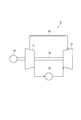
- FIG. 1 is a schematic diagram of a gas turbine that is an example of a target device.
- the gas turbine T includes a compressor T1, a combustor T2, a turbine T3, a rotor T5, a bleed pipe T4, and a generator T6.
- the compressor T1, the turbine T3, and the generator T6 are joined to the rotor T5 and rotate around the axis of the rotor T5.
- the compressor T1 takes in air from the air intake by rotation and compresses the taken-in air to generate compressed air.
- the combustor T2 generates high-temperature and high-pressure combustion gas by injecting fuel into the compressed air generated by the compressor T1. Cooling steam is blown onto the combustor T2 for cooling the combustor T2.
- the turbine T3 converts the thermal energy of the combustion gas generated by the combustor T2 into rotational energy of the rotor T5 to generate a driving force.
- One end of the extraction pipe T4 is connected to the compressor T1, and the other end is connected to the turbine T3.
- the extraction pipe T4 extracts a part of the compressed air generated by the compressor T1, and supplies the extracted compressed air (cooling air) to the turbine T3, thereby cooling the turbine T3.
- the generator T6 converts the rotational energy of the rotor T5 into electric energy.
- a plurality of sensors are attached to the gas turbine T.
- sensor values acquired by each sensor include atmospheric pressure, atmospheric temperature, atmospheric relative humidity, compressor T1 inlet differential pressure, compressor T1 outlet air temperature, compressor T1 outlet air pressure, fuel pressure, Fuel temperature, fuel heating value, fuel composition, fuel flow rate, cooling steam pressure, cooling steam temperature, cooling steam flow rate, cooling air temperature, cooling air flow rate, exhaust temperature, intake pressure loss, exhaust pressure loss, generator T6 Examples include power generation efficiency, generated power, generated current, generated voltage, and generated frequency.
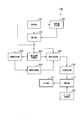
- FIG. 2 is a schematic block diagram illustrating the configuration of the monitoring device according to the first embodiment.
- the monitoring apparatus 100 includes an acquisition unit 101, a characteristic value calculation unit 102, a correction unit 103, a unit space storage unit 104, a distance calculation unit 105, an abnormality determination unit 106, an SN ratio calculation unit 107, a likelihood calculation unit 108, and a table storage unit. 109, an estimation unit 110, and an output unit 111.
- the acquisition unit 101 acquires a sensor value acquired by a sensor provided in the gas turbine T and a control signal value (command value) of the gas turbine T.
- the sensor value acquired by the acquisition unit 101 includes at least the temperature of air and fuel (input fluid) input to the gas turbine T and the temperature of exhaust gas (output fluid) output from the gas turbine T. Including.
- the sensor value is an example of a measured value of the gas turbine T.
- the characteristic value calculation unit 102 calculates a characteristic value indicating the characteristic of the gas turbine T based on the sensor value acquired by the acquisition unit 101. Examples of characteristic values include thermal efficiency, compressor efficiency, combustion efficiency, turbine efficiency, compressor power, turbine output, gas turbine air flow rate, gas turbine exhaust flow rate, compressor pressure ratio, turbine T3 inlet combustion gas temperature. It is done.
- the characteristic value calculation unit 102 divides the difference between the compressor outlet enthalpy and the compressor inlet enthalpy in the isentropic change by the difference between the actual compressor outlet enthalpy and the compressor inlet enthalpy, thereby improving the compressor efficiency (characteristics). Value).
- Enthalpy is calculated using temperature and pressure as sensor values.
- the characteristic value is an example of a measured value of the gas turbine T.
- the characteristic values calculated by the characteristic value calculation unit 102 include at least the flow rate of air input to the gas turbine T and the flow rate of exhaust gas output from the gas turbine T as described above.
- the correction unit 103 obtains a corrected measurement value by correcting the sensor value acquired by the acquisition unit 101 and the characteristic value calculated by the characteristic value calculation unit 102 based on the thermal balance calculation of the gas turbine T. Specifically, the correction unit 103 corrects the measurement value according to the following procedure. First, the correction
- the thermal equilibrium of the entire gas turbine T is represented by the following formula (1).
- the thermal equilibrium of the compressor T1 is represented by the following formula (2).
- the thermal balance of the combustor T2 is expressed by the following formula (3).
- the thermal balance of the turbine T3 is expressed by the following equation (4).
- the left side indicates the amount of heat input, and the right side indicates the amount of heat output.
- the variable G1 indicates the intake flow rate.
- the variable H1C indicates the intake enthalpy.
- the variable G2 indicates the outlet flow rate of the compressor T1.
- the variable H2C indicates the outlet enthalpy of the compressor T1.
- the variable Gf indicates the fuel flow rate.
- a variable LHV indicates the amount of heat generated by the fuel.
- the variable Gst indicates the cooling steam flow rate.
- the variable Hst1 indicates the enthalpy of the cooling steam supplied to the combustor T2.
- the variable Hst2 indicates the enthalpy of the cooling steam discharged from the combustor T2.
- the variable Gc indicates the amount of cooling air.
- the variable Hc represents the cooling air enthalpy.
- the variable G4 indicates the inlet flow rate of the turbine T3.
- the variable H1T indicates the inlet enthalpy of the turbine T3.
- a variable G8 indicates the exhaust gas flow rate.
- the variable H2T indicates the exhaust enthalpy.
- the variable ⁇ GEN indicates the power generation efficiency.
- the variable ⁇ BURN indicates the combustion efficiency.
- the variable KWGEN indicates the generated power.
- the variable KWC indicates the compressor power.
- the variable KWT indicates the turbine output.
- the unit space storage unit 104 has a start period of the gas turbine T (for example, a period of two weeks from the most recent point in time when the gas turbine T starts operating in a new state or when the gas turbine T starts operating after completion of the periodic inspection).
- the combination of the state quantities (measured value, corrected measured value, and command value) of the gas turbine T acquired during () is stored as a unit space of Mahalanobis distance.
- the distance calculation unit 105 uses the sensor values and command values acquired by the acquisition unit 101, the characteristic values calculated by the characteristic value calculation unit 102, and the corrected measurement values corrected by the correction unit 103 as specifications. Based on the stored unit space, a Mahalanobis distance indicating the state of the gas turbine T is calculated.
- the Mahalanobis distance is a measure that represents the magnitude of the difference between a reference sample expressed as a unit space and a newly obtained sample. A method for calculating the Mahalanobis distance will be described later.
- the abnormality determination unit 106 determines whether an abnormality has occurred in the gas turbine T based on the Mahalanobis distance calculated by the distance calculation unit 105. Specifically, the abnormality determination unit 106 determines that an abnormality has occurred in the gas turbine T when the Mahalanobis distance is equal to or greater than a predetermined threshold (for example, 3.5).
- the threshold is usually set to a value of 3 or more.
- the SN ratio calculation unit 107 when the abnormality determination unit 106 determines that an abnormality has occurred in the gas turbine T, the sensor value and command value acquired by the acquisition unit 101, the characteristic value calculated by the characteristic value calculation unit 102, In addition, an SN ratio (Signal-Noise Ratio) related to the Taguchi method is calculated based on the corrected measurement value corrected by the correction unit 103. That is, the likelihood calculating unit 108 obtains a desired SN ratio for the presence / absence of an item by orthogonal table analysis. It can be determined that the higher the S / N ratio, the higher the possibility that there is an abnormality in the item of the state quantity (measured value, command value).
- the likelihood calculating unit 108 calculates the likelihood of occurrence of each of a plurality of events (performance degradation) that can occur in the gas turbine T based on the SN ratio calculated by the SN ratio calculating unit 107.
- events include gas turbine output decline, gas turbine efficiency decline, compressor efficiency decline, turbine efficiency decline, compressor inlet air volume decline, exhaust temperature rise, compressor compression ratio decline, combustion Examples include reduction in efficiency, increase in turbine inlet gas temperature, and increase in exhaust gas pressure.
- the likelihood calculating unit 108 stores, for each event, the relationship between the occurrence of the event and the state quantity that is dominantly involved in the increase / decrease in the SN ratio, and each state quantity associated with each event The likelihood of occurrence of each event is calculated by calculating the weighted sum of the S / N ratios.
- the table storage unit 109 stores a table representing the relationship between the event and the cause of the abnormality. Specifically, the table storage unit 109 stores, for each event and each occurrence factor, the number of times that the event has been confirmed when an abnormality due to the occurrence factor has occurred. For example, when an abnormality due to damage (occurrence factor) of the exhaust diffuser has occurred in the past, and a state (event) in which the deviation of the blade path temperature is large is confirmed nine times, the table storage unit 109 stores the number of times “9” in association with the occurrence factor “damage of the exhaust diffuser” and the event “the state where the deviation of the blade path temperature is large”.
- the table stored in the table storage unit 109 can be generated based on, for example, FTA (Fault Tree Analysis) data generated by maintenance personnel during operation of the gas turbine T.
- FTA ault Tree Analysis
- the estimation unit 110 estimates the cause of the abnormality of the gas turbine T based on the likelihood of occurrence of each event calculated by the likelihood calculation unit 108 and the table stored in the table storage unit 109. Specifically, the estimation unit 110 performs multiplication of a 1-row M-column vector having the likelihood of occurrence of each event as an element and an M-by-N matrix having a table value as an element, An N-by-1 vector having the likelihood of the cause of the abnormality as an element is obtained. M represents the number of events, and N represents the number of occurrence factors. And the estimation part 110 can estimate that the generation factor which concerns on the row
- the output unit 111 outputs the generation factors estimated by the estimation unit 110 in order of likelihood. Examples of output include display on a display, transmission of data to the outside, printing on a sheet, audio output, and the like.
- u be the number of items of a plurality of state quantities (measured values, command values) representing the state of the gas turbine T.
- u is an integer of 2 or more.
- the state quantities of the u item are X 1 to X u respectively.
- the monitoring device 100 operates in the operation state of the gas turbine T serving as a reference (in the first embodiment, the latest operation time of the gas turbine T in a new state or the operation start time of the gas turbine T after completion of the periodic inspection). In the operation state for two weeks from the time), a total of v (2 or more) of state quantities X 1 to X u of each item are collected.
- v 60.
- the j-th state quantities X 1 to X u of each item collected in the operating state are set as X 1j to X uj .
- j takes any value (integer) from 1 to v, meaning that the number of each state quantity is v. That is, the monitoring apparatus 100 collects the state quantities X 11 to X uv .
- the state quantities X 11 to X uv are stored in the unit space storage unit 104.
- the monitoring apparatus 100 obtains the average value M i and the standard deviation ⁇ i (the degree of variation of the reference data) for each item of the state quantities X 11 to X uv according to the expressions (5) and (6).
- i is the number of items (number of state quantities, integer).
- i is set to 1 to u and represents a value corresponding to the state quantities X 1 to X u .
- the standard deviation is the square root of the expected value of the difference between the state quantity and its average value squared.
- the above-mentioned average value M i and standard deviation ⁇ i are state quantities indicating features.
- the monitoring apparatus 100 uses the calculated average value M i and standard deviation ⁇ i to convert the state quantities X 11 to X uv into the standardized state quantities x 11 to x uv according to the following equation (7). Convert. That is, the abnormality monitoring apparatus 10 converts the state quantity X ij of the gas turbine T into a random variable x ij having an average of 0 and a standard deviation of 1.
- j takes any value (integer) from 1 to v. This means that the number of state quantities for each item is v.
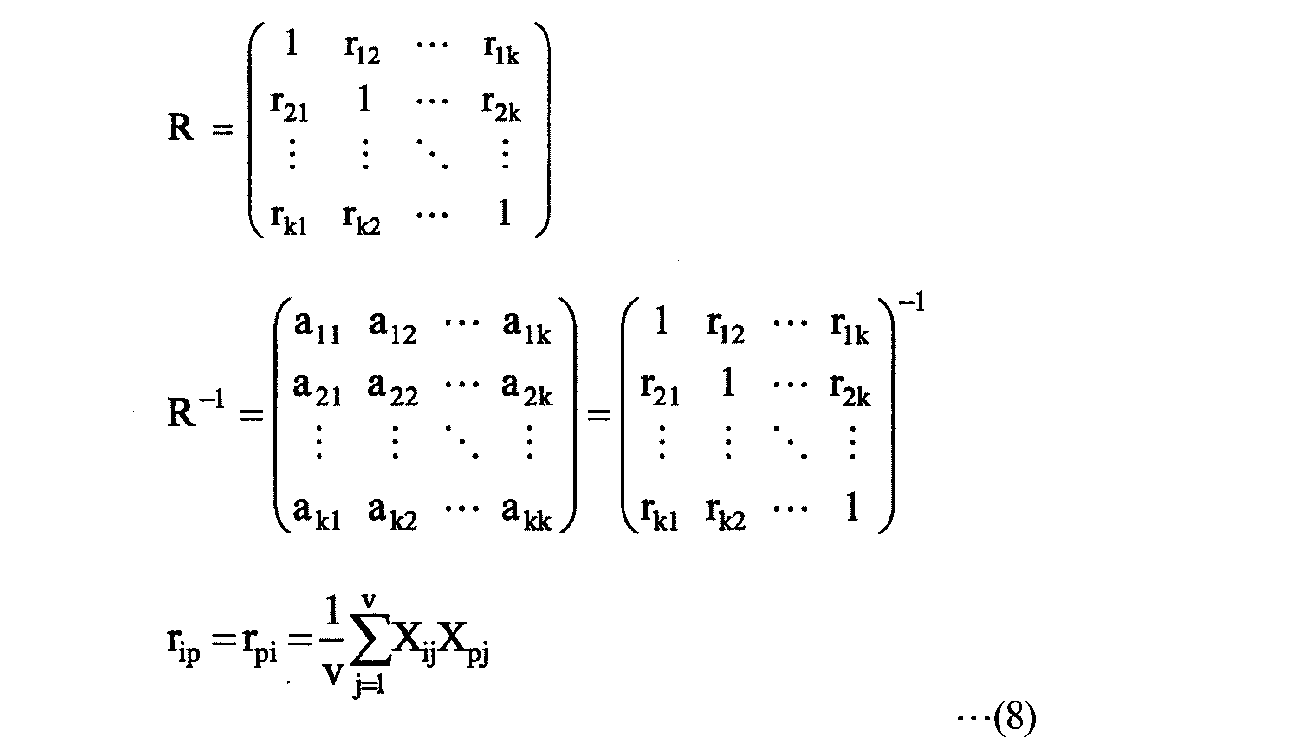
- the monitoring apparatus 100 specifies the correlation between the state quantities X 11 to X uv . That is, the monitoring apparatus 100 defines a covariance matrix (correlation matrix) R indicating the relationship between the variables and an inverse matrix R ⁇ 1 of the covariance matrix (correlation matrix) by the following formula (8).
- k is the number of items (number of state quantities). That is, k is equal to u.
- i and p represent values in the respective state quantities, and take values of 1 to u here.
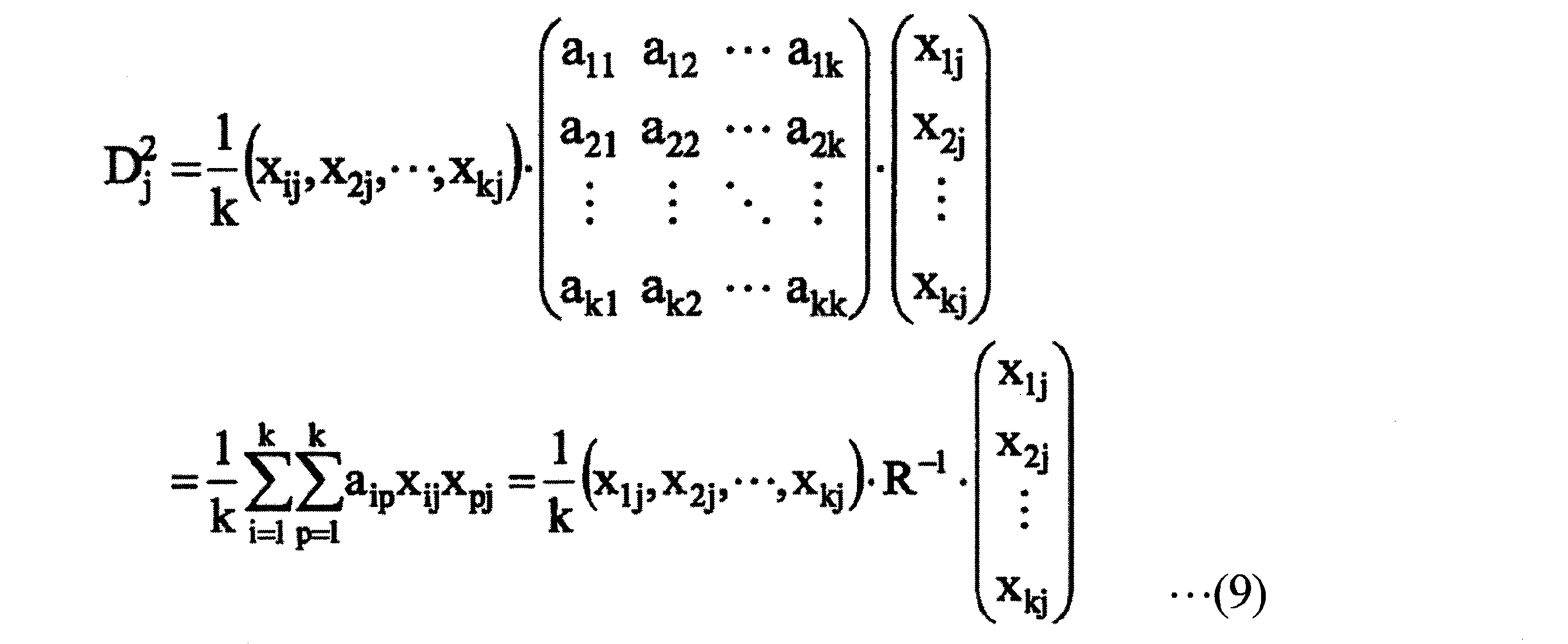
- the monitoring apparatus 100 calculates
- j takes any value (integer) from 1 to v. This means that the number of state quantities for each item is v.
- K is the number of items (number of state quantities). That is, k is equal to u.
- a 11 to a kk are coefficients of the inverse matrix R ⁇ 1 of the covariance matrix R shown in the above equation (8).
- Mahalanobis distance D is reference data.
- the average value of the Mahalanobis distance D in the unit space is 1.
- the Mahalanobis distance D is approximately 3 or less.
- the value of the Mahalanobis distance D is generally larger than 3.
- the Mahalanobis distance D has a property that the value increases according to the degree of abnormality of the state quantity of the gas turbine T (the degree of separation from the unit space).
- FIG. 3 is a flowchart showing the operation of the monitoring apparatus according to the first embodiment.
- the monitoring device 100 collects the state quantities of the gas turbine T and accumulates the state quantity combinations in the unit space storage unit 104 during the start-up period of the gas turbine T. That is, the monitoring apparatus 100 records the command value of the gas turbine acquired by the acquisition unit 101 and the corrected measurement value generated by the correction unit 103 in the unit space storage unit 104 in association with each other.
- the monitoring device 100 performs the following monitoring operation at a predetermined monitoring timing (for example, every other hour) after the start period of the gas turbine T elapses.
- the monitoring timing is an example of a time point after starting, which is a time point after a predetermined starting period has elapsed since the operation start time of the gas turbine T.
- the acquisition unit 101 acquires a sensor value acquired by a sensor provided in the gas turbine T and a command value of the gas turbine T (step S1).
- the characteristic value calculation unit 102 calculates a characteristic value indicating the characteristic of the gas turbine T based on the sensor value acquired by the acquisition unit 101 (step S2).
- amendment part 103 acquires a correction
- the distance calculation unit 105 stores the unit space storage unit 104 using the sensor value and command value acquired in step S1, the characteristic value calculated in step S2, and the corrected measurement value obtained in step S3 as specifications. Based on the unit space to be calculated, the Mahalanobis distance is calculated (step S4). Next, the abnormality determination unit 106 determines whether or not the calculated Mahalanobis distance is greater than or equal to a predetermined threshold (step S5).
- step S5 NO
- the abnormality determining unit 106 determines that no abnormality has occurred in the gas turbine T, ends the monitoring process, and waits for the next monitoring timing.
- the Mahalanobis distance is greater than or equal to the threshold (step S5: YES)
- the abnormality determination unit 106 determines that an abnormality has occurred in the gas turbine T.
- the SN ratio calculation unit 107 relates to the Taguchi method for each of the command value acquired in step S1 and the corrected measurement value obtained in step S3.
- An SN ratio is calculated (step S6).
- the likelihood calculating unit 108 calculates the likelihood of occurrence of each of a plurality of events that can occur in the gas turbine T based on the calculated S / N ratio (step S7).
- the estimation unit 110 multiplies the vector having the likelihood of each event calculated by the likelihood calculation unit 108 as an element by a matrix having the table value stored in the table storage unit 109 as an element. Then, a vector having the likelihood of the cause of the abnormality as an element is obtained (step S8). Next, the estimation unit 110 sorts the occurrence factors in descending order of the likelihood represented by the obtained vector (step S9). And the output part 111 outputs the information which shows the generation
- the output unit 111 outputs a signal for causing the display of the most likely occurrence factor on the display, and when the next occurrence factor display command is received by a user operation, the next likelihood is Outputs a signal to display a high cause on the display. Further, for example, the output unit 111 outputs a signal for printing the occurrence factor list on the sheet in descending order of likelihood.
- the monitoring apparatus 100 includes the measurement values including the temperature and flow rate of the air and fuel input to the gas turbine T and the temperature and flow rate of the exhaust gas output from the gas turbine T. Is corrected by thermal equilibrium calculation to calculate Mahalanobis distance. Thereby, the monitoring apparatus 100 can reduce the measurement error of the sensor provided in the gas turbine T and calculate the Mahalanobis distance.
- the monitoring device 100 uses the measurement values acquired at the time after starting, which is the time after the predetermined starting time has elapsed from the time when the operation of the gas turbine T starts, as specifications.
- the Mahalanobis distance is calculated using the measurement value acquired during the start-up period as a unit space. That is, the monitoring apparatus 100 calculates the Mahalanobis distance using the normal operating state of the gas turbine T itself that is the monitoring target as a unit space. Conventionally, as the unit space of the Mahalanobis distance, the Mahalanobis distance is determined based on the unit space including the operating state in which the deterioration has occurred after the start period but no abnormality has occurred and the operating state of other gas turbines T. It was calculated.
- the Mahalanobis distance is calculated based on the unit space including only the operating state of the gas turbine T itself that is the monitoring target and before the deterioration occurs.
- the monitoring apparatus 100 can detect an abnormality with high accuracy for the gas turbine T to be monitored.
- the start-up period according to the first embodiment is a period starting from the most recent point in time when starting operation in a new state or starting operation after completion of periodic inspection. That is, the unit space of Mahalanobis distance is updated at every periodic inspection. Thereby, the abnormality of the gas turbine T can be detected on the basis of the normal operation state after the periodic inspection of the gas turbine T (the first operation state in the new state).
- the new state that is, the operating state of the non-deteriorating gas turbine T is used as the unit space
- the Mahalanobis distance becomes relatively large even if the operating state of the gas turbine T after the periodic inspection is normal. This is because it is difficult to completely repair deterioration due to the use of the gas turbine T by periodic inspection. Therefore, it is possible to accurately determine the operation state by detecting the abnormality of the gas turbine T with reference to the normal operation state after the periodic inspection of the gas turbine T.
- the monitoring apparatus 100 calculates the likelihood of occurrence of each of a plurality of events that may occur in the gas turbine T, and a table indicating the relationship between the event and the cause of the abnormality and the likelihood.
- the cause of the abnormality is estimated based on the degree.
- the monitoring apparatus 100 can easily output the cause of the abnormality based on the observed event.
- the structure of other embodiment is not restricted to this.
- the monitoring apparatus 100 according to another embodiment may output only the fact that an abnormality has occurred without estimating the cause of the abnormality.
- the monitoring apparatus 100 according to another embodiment may notify the user of an S / N ratio of a state quantity or an event that is likely to occur without outputting a cause of the abnormality of the event.
- the monitoring apparatus 100 calculates the Mahalanobis distance using the measured value, the corrected measured value, and the command value as specifications. Thereby, even when the balance between the heat input amount and the heat output amount is lost due to deterioration of the gas turbine T or the like, the state of the gas turbine T can be appropriately evaluated.
- the structure of other embodiment is not restricted to this.
- the monitoring apparatus 100 according to another embodiment may calculate the Mahalanobis distance using the corrected measurement value as a specification without including the measurement value as a specification.
- the monitoring device 100 may calculate the Mahalanobis distance without including the command value in the specifications.
- the monitoring device 100 monitors the state of deterioration of the gas turbine T after periodic inspection.
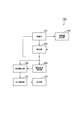
- FIG. 4 is a schematic block diagram illustrating the configuration of the monitoring device according to the second embodiment.
- the monitoring apparatus 100 according to the second embodiment is replaced with the abnormality determination unit 106, the SN ratio calculation unit 107, the likelihood calculation unit 108, the table storage unit 109, and the estimation unit 110 according to the first embodiment.
- An estimation unit 112 is provided.
- the deterioration estimation unit 112 estimates the degree of deterioration based on the Mahalanobis distance calculated by the distance calculation unit 105. Specifically, the deterioration estimation unit 112 estimates that the deterioration progresses as the Mahalanobis distance increases.
- the deterioration estimation unit 112 estimates that the deterioration is “none”, and when the Mahalanobis distance is “1.5” or more and less than “2.5”, When it is estimated that the deterioration is “small” and the Mahalanobis distance is “2.5” or more and less than “3.5”, when the deterioration is estimated as “medium” and the Mahalanobis distance is “3.5” or more, It is estimated that the deterioration is “large”.
- the unit space storage unit 104 acquires the gas acquired during the start-up period of the new gas turbine T (for example, a period of two weeks from the start of operation of the new gas turbine T). A combination of the corrected measured value and the command value of the turbine T is stored as a unit space of Mahalanobis distance.
- FIG. 5 is a flowchart showing the operation of the monitoring apparatus according to the second embodiment.
- the monitoring device 100 collects the state quantities of the gas turbine T and accumulates the state quantity combinations in the unit space storage unit 104 during the start-up period of the new gas turbine T. That is, the monitoring apparatus 100 records the command value of the gas turbine acquired by the acquisition unit 101 and the corrected measurement value generated by the correction unit 103 in the unit space storage unit 104 in association with each other.
- the monitoring device 100 executes the following monitoring operation at a timing during a predetermined period (for example, two weeks) starting from the operation start time after completion of the periodic inspection of the gas turbine T.
- a predetermined period for example, two weeks
- the acquisition unit 101 acquires the sensor value acquired by the sensor provided in the gas turbine T and the command value of the gas turbine T (step S101).
- the characteristic value calculation unit 102 calculates a characteristic value indicating the characteristic of the gas turbine T based on the sensor value acquired by the acquisition unit 101 (step S102).
- amendment part 103 acquires a correction
- the distance calculation unit 105 calculates the Mahalanobis distance based on the unit space stored in the unit space storage unit 104 using the command value obtained in step S101 and the corrected measurement value obtained in step S103 as specifications. (Step S104).
- the deterioration estimation unit 112 estimates the degree of deterioration based on the calculated Mahalanobis distance (step S105).
- the output unit 111 outputs the degree of deterioration estimated by the deterioration estimation unit 112 (step S106).
- the monitoring device 100 uses the state quantity of the start period starting from the operation start time of the new gas turbine T as a unit space, and the gas turbine T after the periodic inspection has The Mahalanobis distance is calculated using the state quantity at the time after the start of operation as specifications. Thereby, the monitoring apparatus 100 can estimate how much the gas turbine T recovered by the periodic inspection has deteriorated as compared with the new state.
- the unit space storage unit 104 stores the state quantity acquired during the start-up period of the new gas turbine T as a unit space of the Mahalanobis distance, but is not limited thereto.
- the unit space storage unit 104 may store a performance prediction value obtained by simulation using a physical model of the gas turbine T as a unit space of Mahalanobis distance.
- the monitoring apparatus 100 calculates the Mahalanobis distance by standardizing the corrected measurement value generated by the correction unit 103 based on atmospheric conditions.
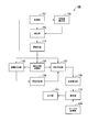
- FIG. 6 is a schematic block diagram illustrating the configuration of the monitoring device according to the third embodiment.
- the monitoring apparatus 100 according to the third embodiment further includes a standardization unit 113 in addition to the configuration of the first embodiment.
- the standardization unit 113 uses the atmospheric conditions (atmospheric pressure, atmospheric temperature, atmospheric humidity, etc.) among the sensor values acquired by the acquisition unit 101, and uses the corrected measurement values generated by the correction unit 103 as values related to the standard atmospheric conditions.
- the acquisition unit 101 is an example of an atmospheric condition acquisition unit that acquires atmospheric conditions.
- Examples of the corrected measurement values to be standardized include output power, heat consumption rate, exhaust flow rate, intake flow rate, exhaust energy, and exhaust temperature.
- the standardization unit 113 stores in advance a function representing the relationship between the atmospheric condition and a coefficient for standardization of the corrected measurement value (standardization coefficient), and substitutes the atmospheric condition into the function. Identify standardization factors for standard atmospheric conditions. Next, the standardization unit 113 specifies the standardized correction measurement value by multiplying the correction measurement value by the standardization coefficient.
- a function representing the relationship between the atmospheric condition and the standardization coefficient By using a physical model of the gas turbine T in advance and calculating a measurement value by changing a variable related to atmospheric conditions in a predetermined domain, a curve indicating the relationship between the variable and the standardization coefficient can be obtained. .
- a variable function expression is generated for the standardization coefficient that depends on a plurality of variables related to atmospheric conditions. In this case, a variable related to the atmospheric condition is changed one by one, and an equation indicating the relationship between the variable and the standardization coefficient is obtained for each variable.
- the domain of the function representing the relationship between the atmospheric condition and the standardization coefficient according to the first embodiment is a range that is assumed from the standard state or the designated reference condition of the gas turbine T.
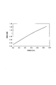
- FIG. 7 is a graph showing an example of a function representing the relationship between the atmospheric condition and the standardization coefficient.
- the distance calculation unit 105 calculates the Mahalanobis distance using the command value acquired by the acquisition unit 101 and the corrected measurement value standardized by the standardization unit 113 as specifications.
- the unit space of the Mahalanobis distance can be simplified by standardizing the corrected measurement value under atmospheric conditions, and the accuracy of abnormality determination by the abnormality determination unit 106 is improved. be able to.
- the standardization unit 113 can improve the linearity of the Mahalanobis distance by standardizing the flow rate to the standard atmospheric pressure condition.
- the standardization unit 113 according to the third embodiment standardizes the corrected measurement value corrected by the correction unit 103, but is not limited thereto.
- the standardization unit 113 according to another embodiment may standardize the sensor value acquired by the acquisition unit 101 to a value related to atmospheric conditions.
- the characteristic value calculation unit 102 calculates a characteristic value using the standardized sensor value
- the correction unit 103 calculates a corrected measurement value using the standardized sensor value and characteristic value.
- the standardization unit 113 according to another embodiment may standardize the corrected measurement value or the measurement value by using any one or two of atmospheric pressure, atmospheric temperature, and atmospheric humidity.
- a deterioration estimation unit may further include a standardization unit 113.
- the monitoring apparatus 100 determines whether to calculate the Mahalanobis distance based on the measurement value.
- FIG. 8 is a schematic block diagram illustrating the configuration of the monitoring device according to the fourth embodiment.
- the monitoring apparatus 100 according to the fourth embodiment further includes a linearity determination unit 114 in addition to the configuration of the first embodiment.
- the linearity determination unit 114 has a sensor value T related to temperature that is greater than or equal to the minimum value of the sensor values T stored in the unit space storage unit 104 and the sensor value T It is determined whether it is less than the maximum value of.
- the linearity determination unit 114 determines whether the Mahalanobis distance maintains the linearity of the relationship between temperature and output in the unit space. .
- the distance calculation unit 105 calculates the Mahalanobis distance based on the sensor value. On the other hand, when the linearity determination unit 114 determines that the sensor value is not within the range of the sensor values stored in the unit space storage unit 104, the distance calculation unit 105 does not calculate the Mahalanobis distance and resets the timing. The Mahalanobis distance is calculated again (for example, after a predetermined time).
- the monitoring apparatus 100 does not calculate the Mahalanobis distance when there is a possibility that the linearity of the relationship between the temperature and the output cannot be maintained, so that the erroneous determination by the abnormality determination unit 106 is performed. Can be prevented.
- a deterioration estimation unit may further include the abnormality determination unit 106.
- the target apparatus according to the above-described embodiment is the gas turbine T, but is not limited to this in other embodiments.
- the target device according to another embodiment may be a steam turbine, an engine, or another device having a thermal balance.
- FIG. 9 is a schematic block diagram illustrating a configuration of a computer according to at least one embodiment.
- the computer 900 includes a CPU 901, a main storage device 902, an auxiliary storage device 903, and an interface 904.
- the monitoring device 100 described above includes a computer 900.
- the operation of each processing unit described above is stored in the auxiliary storage device 903 in the form of a program.
- the CPU 901 reads a program from the auxiliary storage device 903, develops it in the main storage device 902, and executes the above processing according to the program. Further, the CPU 901 secures a storage area corresponding to each of the above-described storage units in the main storage device 902 according to the program.
- the auxiliary storage device 903 is an example of a tangible medium that is not temporary.
- Other examples of the tangible medium that is not temporary include a magnetic disk, a magneto-optical disk, an optical disk, and a semiconductor memory connected via the interface 904.
- the program may be for realizing a part of the functions described above. Further, the program may be a so-called difference file (difference program) that realizes the above-described function in combination with another program already stored in the auxiliary storage device 903.
- difference file difference program
- the monitoring device can reduce an error included in the measurement value by correcting the measurement value by performing a thermal equilibrium calculation.
- the monitoring apparatus can calculate the Mahalanobis distance while reducing the influence of the error included in the measurement value.
Landscapes
- Engineering & Computer Science (AREA)
- Mechanical Engineering (AREA)
- Combustion & Propulsion (AREA)
- Chemical & Material Sciences (AREA)
- General Engineering & Computer Science (AREA)
- Physics & Mathematics (AREA)
- General Physics & Mathematics (AREA)
- Automation & Control Theory (AREA)
- Human Computer Interaction (AREA)
- Manufacturing & Machinery (AREA)
- Testing And Monitoring For Control Systems (AREA)
- Investigating Or Analyzing Materials Using Thermal Means (AREA)
- Measuring Volume Flow (AREA)
Abstract
取得部は、対象装置の計測値を取得する。取得される計測値は、少なくとも対象装置に入力される入力流体の温度および流量、ならびに対象装置から出力される出力流体の温度および流量を含む。補正部は、計測値に基づく熱平衡計算により、計測値を補正した補正計測値を得る。距離算出部は、補正計測値を諸元としてマハラノビス距離を算出する。
Description
本発明は、対象装置を監視する監視装置、対象装置の監視方法、およびプログラムに関する。
本願は、2016年6月1日に日本に出願された特願2016-110337号について優先権を主張し、その内容をここに援用する。
本願は、2016年6月1日に日本に出願された特願2016-110337号について優先権を主張し、その内容をここに援用する。
プラントの運転状態を監視するシステムとして、マハラノビス距離を用いるものが知られている(例えば、特許文献1を参照)。特許文献1に記載のシステムは、マハラノビス距離に基づいてプラントの異常の予兆の監視から故障診断までの一連の処理を行う。
マハラノビス距離、およびマハラノビス距離の算出に用いる単位空間を求めるには、プラントを構成する機器である対象装置から収集された状態量が必要となる。状態量の例としては、対象装置を制御するための制御信号の値、および対象装置に設けられたセンサが出力する計測値が挙げられる。
しかしながら、対象装置に設けられるセンサが出力する計測値には、計測誤差が含まれる。そのため、計測値を用いて算出されるマハラノビス距離は、誤差の影響を受ける可能性がある。
本発明の目的は、計測値に含まれる誤差の影響を低減してマハラノビス距離を算出することができる監視装置、対象装置の監視方法、およびプログラムを提供することにある。
しかしながら、対象装置に設けられるセンサが出力する計測値には、計測誤差が含まれる。そのため、計測値を用いて算出されるマハラノビス距離は、誤差の影響を受ける可能性がある。
本発明の目的は、計測値に含まれる誤差の影響を低減してマハラノビス距離を算出することができる監視装置、対象装置の監視方法、およびプログラムを提供することにある。
本発明の第1の態様によれば、監視装置は、対象装置の計測値であって、少なくとも前記対象装置に入力される入力流体の温度および流量、ならびに前記対象装置から出力される出力流体の温度および流量を含む計測値を取得する取得部と、前記計測値に基づく熱平衡計算により、前記計測値を補正した補正計測値を得る補正部と、前記補正計測値を諸元としてマハラノビス距離を算出する距離算出部と、を備える。
本発明の第2の態様によれば、第1の態様に係る監視装置は、前記距離算出部が、前記計測値および前記補正計測値を諸元として前記マハラノビス距離を算出するものであってよい。
本発明の第3の態様によれば、第1または第2の態様に係る監視装置は、大気圧、大気温度および大気湿度の少なくとも一つを含む大気条件を取得する大気条件取得部と、取得した前記大気条件を用いて、前記計測値または前記補正計測値を標準大気条件下における値に標準化する標準化部とをさらに備え、前記距離算出部が、標準化された前記計測値または標準化された前記補正計測値に基づいて前記マハラノビス距離を算出するものであってよい。
本発明の第4の態様によれば、第1から第3の何れかの態様に係る監視装置は、前記マハラノビス距離が所定値以上である場合に、前記計測値または前記補正計測値に基づいて前記対象装置に生じ得る複数の事象それぞれの発生の尤度を算出する尤度算出部と、前記複数の事象と前記対象装置の異常の発生要因とを関連付けたテーブルを記憶するテーブル記憶部と、前記尤度と前記テーブルとに基づいて前記発生要因を推定する推定部とを備えるものであってよい。
本発明の第5の態様によれば、第1から第4の何れかの態様に係る監視装置は、前記取得部が取得した温度に係る前記計測値について、当該計測値が前記マハラノビス距離の単位空間を構成する温度に係る計測値の最小値以上かつ最大値以下であるか否かを判定する線形性判定部をさらに備え、前記距離算出部は、前記線形性判定部により、前記単位空間における温度に係る計測値の最小値以上かつ最大値以下でないと判定された場合に、前記計測値に基づくマハラノビス距離の算出を行わないものであってよい。
本発明の第6の態様によれば、第1から第5の何れかの態様に係る監視装置は、前記取得部は、前記対象装置の運転開始時点を始点とする所定の始動期間の経過後の時点である始動後時点における前記計測値を取得し、前記距離算出部は、前記始動期間中の時点における計測値を用いて生成された単位空間に基づいて、前記取得部が取得した前記計測値に基づいて前記マハラノビス距離を算出するものであってよい。
本発明の第7の態様によれば、監視装置は、対象装置の運転開始時点から所定の始動期間が経過した後の時点である始動後時点に、前記対象装置の計測値を取得する取得部と、前記始動期間中の時点における計測値を用いて生成された単位空間に基づいて、前記取得部が取得した前記計測値に基づいてマハラノビス距離を算出する距離算出部とを備える。
本発明の第8の態様によれば、第6または第7の態様に係る監視装置は、前記始動期間は、新品状態の前記対象装置の運転開始時点を始点とする期間であり、前記始動後時点は、前記対象装置の定期点検の完了後の運転開始時点を始点とする所定期間中の時点であるものであってよい。
本発明の第9の態様によれば、第6または第7の態様に係る監視装置は、前記始動期間は、新品状態の運転開始時点または定期点検の完了後の運転開始時点のうち直近の時点を始点とする期間であるものであってよい。
本発明の第10の態様によれば、対象装置の監視方法は、対象装置の計測値であって、少なくとも前記対象装置に入力される入力流体の温度および流量、ならびに前記対象装置から出力される出力流体の温度および流量を含む計測値を取得することと、前記計測値に基づく熱平衡計算により、前記計測値を補正した補正計測値を得ることと、前記補正計測値を諸元としてマハラノビス距離を算出することと、を含む。
本発明の第11の態様によれば、第10の態様に係る対象装置の監視方法は、前記計測値および前記補正計測値を諸元として前記マハラノビス距離を算出するものであってよい。
本発明の第12の態様によれば、第10または第11の態様に係る対象装置の監視方法は、大気圧および大気湿度の少なくとも一方を含む大気条件を取得することと、取得した前記大気条件を用いて、前記計測値または前記補正計測値を標準大気条件下における値に標準化することとをさらに含み、標準化された前記計測値または標準化された前記補正計測値に基づいて前記マハラノビス距離を算出するものであってよい。
本発明の第13の態様によれば、対象装置の監視方法は、対象装置の運転開始時点から所定の始動期間が経過した後の時点である始動後時点に、前記対象装置の計測値を取得することと、前記始動期間中の時点における計測値を用いて生成された単位空間に基づいて、取得した前記計測値に基づいてマハラノビス距離を算出することとを含む。
本発明の第14の態様によれば、プログラムは、コンピュータに、対象装置の計測値であって、少なくとも前記対象装置に入力される入力流体の温度および流量、ならびに前記対象装置から出力される出力流体の温度および流量を含む計測値を取得することと、前記計測値に基づく熱平衡計算により、前記計測値を補正した補正計測値を得ることと、前記補正計測値を諸元としてマハラノビス距離を算出することと、を実行させる。
上記態様のうち少なくとも1つの態様によれば、監視装置は、熱平衡計算を行うことで計測値を補正することで、計測値に含まれる誤差を低減することができる。これにより、監視装置は、計測値に含まれる誤差の影響を低減してマハラノビス距離を算出することができる。
〈第1の実施形態〉
以下、図面を参照しながら第1の実施形態について詳しく説明する。
第1の実施形態に係る監視装置100は、ガスタービンTの異常の有無を監視し、異常の発生要因を特定する。ガスタービンTは対象装置の一例である。
以下、図面を参照しながら第1の実施形態について詳しく説明する。
第1の実施形態に係る監視装置100は、ガスタービンTの異常の有無を監視し、異常の発生要因を特定する。ガスタービンTは対象装置の一例である。
《対象装置》
図1は、対象装置の一例であるガスタービンの模式図である。
ガスタービンTは、圧縮機T1、燃焼器T2、タービンT3、ロータT5、抽気管T4、および発電機T6を備える。圧縮機T1、タービンT3、および発電機T6は、ロータT5に接合され、ロータT5の軸回りに回転する。圧縮機T1は、回転により空気取込口から空気を取り込み、取り込んだ空気を圧縮して圧縮空気を生成する。燃焼器T2は、圧縮機T1が生成した圧縮空気に燃料を噴射することにより、高温かつ高圧の燃焼ガスを発生させる。また燃焼器T2には、燃焼器T2の冷却のために冷却蒸気が吹き付けられる。
タービンT3は、燃焼器T2が発生させた燃焼ガスの熱エネルギーをロータT5の回転エネルギーに変換して駆動力を発生させる。抽気管T4は、その一端が圧縮機T1に接続され、その他端がタービンT3に接続される。抽気管T4は、圧縮機T1が生成する圧縮空気の一部を抽気し、抽気した圧縮空気(冷却空気)をタービンT3に供給することで、タービンT3を冷却する。発電機T6は、ロータT5の回転エネルギーを電気エネルギーに変換する。
図1は、対象装置の一例であるガスタービンの模式図である。
ガスタービンTは、圧縮機T1、燃焼器T2、タービンT3、ロータT5、抽気管T4、および発電機T6を備える。圧縮機T1、タービンT3、および発電機T6は、ロータT5に接合され、ロータT5の軸回りに回転する。圧縮機T1は、回転により空気取込口から空気を取り込み、取り込んだ空気を圧縮して圧縮空気を生成する。燃焼器T2は、圧縮機T1が生成した圧縮空気に燃料を噴射することにより、高温かつ高圧の燃焼ガスを発生させる。また燃焼器T2には、燃焼器T2の冷却のために冷却蒸気が吹き付けられる。
タービンT3は、燃焼器T2が発生させた燃焼ガスの熱エネルギーをロータT5の回転エネルギーに変換して駆動力を発生させる。抽気管T4は、その一端が圧縮機T1に接続され、その他端がタービンT3に接続される。抽気管T4は、圧縮機T1が生成する圧縮空気の一部を抽気し、抽気した圧縮空気(冷却空気)をタービンT3に供給することで、タービンT3を冷却する。発電機T6は、ロータT5の回転エネルギーを電気エネルギーに変換する。
ガスタービンTには図示しない複数のセンサが取り付けられる。各センサが取得するセンサ値の例としては、大気圧、大気温度、大気の相対湿度、圧縮機T1の入口差圧、圧縮機T1の出口空気温度、圧縮機T1の出口空気圧力、燃料圧力、燃料温度、燃料発熱量、燃料組成、燃料流量、冷却蒸気圧力、冷却蒸気温度、冷却蒸気流量、冷却空気の温度、冷却空気の流量、排気温度、吸気圧力損失、排気圧力損失、発電機T6の発電効率、発電電力、発電電流、発電電圧、発電周波数が挙げられる。
《構成》
監視装置100の構成について説明する。図2は、第1の実施形態に係る監視装置の構成を示す概略ブロック図である。
監視装置100は、取得部101、特性値算出部102、補正部103、単位空間記憶部104、距離算出部105、異常判定部106、SN比算出部107、尤度算出部108、テーブル記憶部109、推定部110、出力部111を備える。
取得部101は、ガスタービンTに設けられたセンサが取得したセンサ値、およびガスタービンTの制御信号の値(指令値)を取得する。なお、取得部101が取得するセンサ値には、上述の通り、少なくともガスタービンTに入力される空気および燃料(入力流体)の温度およびガスタービンTから出力される排気(出力流体)の温度を含む。センサ値は、ガスタービンTの計測値の一例である。
特性値算出部102は、取得部101が取得したセンサ値に基づいて、ガスタービンTの特性を示す特性値を算出する。特性値の例としては、熱効率、圧縮機効率、燃焼効率、タービン効率、圧縮機動力、タービン出力、ガスタービン空気流量、ガスタービン排気流量、圧縮機圧力比、タービンT3の入口燃焼ガス温度が挙げられる。例えば、特性値算出部102は、等エントロピ変化における圧縮機出口エンタルピと圧縮機入口エンタルピの差を、実際の圧縮機出口エンタルピと圧縮機入口エンタルピの差で除算することで、圧縮機効率(特性値)を算出する。エンタルピは、センサ値である温度および圧力を用いて算出される。特性値は、ガスタービンTの計測値の一例である。なお、特性値算出部102が算出する特性値には、上述の通り、少なくともガスタービンTに入力される空気の流量およびガスタービンTから出力される排気の流量を含む。
監視装置100の構成について説明する。図2は、第1の実施形態に係る監視装置の構成を示す概略ブロック図である。
監視装置100は、取得部101、特性値算出部102、補正部103、単位空間記憶部104、距離算出部105、異常判定部106、SN比算出部107、尤度算出部108、テーブル記憶部109、推定部110、出力部111を備える。
取得部101は、ガスタービンTに設けられたセンサが取得したセンサ値、およびガスタービンTの制御信号の値(指令値)を取得する。なお、取得部101が取得するセンサ値には、上述の通り、少なくともガスタービンTに入力される空気および燃料(入力流体)の温度およびガスタービンTから出力される排気(出力流体)の温度を含む。センサ値は、ガスタービンTの計測値の一例である。
特性値算出部102は、取得部101が取得したセンサ値に基づいて、ガスタービンTの特性を示す特性値を算出する。特性値の例としては、熱効率、圧縮機効率、燃焼効率、タービン効率、圧縮機動力、タービン出力、ガスタービン空気流量、ガスタービン排気流量、圧縮機圧力比、タービンT3の入口燃焼ガス温度が挙げられる。例えば、特性値算出部102は、等エントロピ変化における圧縮機出口エンタルピと圧縮機入口エンタルピの差を、実際の圧縮機出口エンタルピと圧縮機入口エンタルピの差で除算することで、圧縮機効率(特性値)を算出する。エンタルピは、センサ値である温度および圧力を用いて算出される。特性値は、ガスタービンTの計測値の一例である。なお、特性値算出部102が算出する特性値には、上述の通り、少なくともガスタービンTに入力される空気の流量およびガスタービンTから出力される排気の流量を含む。
補正部103は、取得部101が取得したセンサ値および特性値算出部102が算出した特性値をガスタービンTの熱平衡計算に基づいて補正することで、補正計測値を得る。
具体的には、補正部103は、以下の手順で計測値を補正する。まず補正部103は、計測値をガスタービンTに係る熱平衡の式に代入し、当該式が成立するように、各計測値の誤差を算出する。そして補正部103は、計測値ごとに算出した誤差の総和、または誤差の二乗の総和を求め、求められた総和が最小となる計測値ごとの誤差の組み合わせを選択することで、補正計測値を得る。
具体的には、ガスタービンT全体の熱平衡は、以下の式(1)により表される。圧縮機T1の熱平衡は、以下の式(2)により表される。燃焼器T2の熱平衡は、以下の式(3)により表される。タービンT3の熱平衡は、以下の式(4)により表される。以下の式(1)-式(4)において、左辺は入熱量を示し、右辺は出熱量を示す。
具体的には、補正部103は、以下の手順で計測値を補正する。まず補正部103は、計測値をガスタービンTに係る熱平衡の式に代入し、当該式が成立するように、各計測値の誤差を算出する。そして補正部103は、計測値ごとに算出した誤差の総和、または誤差の二乗の総和を求め、求められた総和が最小となる計測値ごとの誤差の組み合わせを選択することで、補正計測値を得る。
具体的には、ガスタービンT全体の熱平衡は、以下の式(1)により表される。圧縮機T1の熱平衡は、以下の式(2)により表される。燃焼器T2の熱平衡は、以下の式(3)により表される。タービンT3の熱平衡は、以下の式(4)により表される。以下の式(1)-式(4)において、左辺は入熱量を示し、右辺は出熱量を示す。




変数G1は、吸気流量を示す。変数H1Cは、吸気エンタルピを示す。変数G2は、圧縮機T1の出口流量を示す。変数H2Cは、圧縮機T1の出口エンタルピを示す。変数Gfは、燃料流量を示す。変数LHVは、燃料発熱量を示す。変数Gstは、冷却蒸気流量を示す。変数Hst1は、燃焼器T2に供給される冷却蒸気のエンタルピを示す。変数Hst2は、燃焼器T2から排出される冷却蒸気のエンタルピを示す。変数Gcは、冷却空気量を示す。変数Hcは、冷却空気エンタルピを示す。変数G4は、タービンT3の入口流量を示す。変数H1Tは、タービンT3の入口エンタルピを示す。変数G8は、排気流量を示す。変数H2Tは、排気エンタルピを示す。変数μGENは、発電効率を示す。変数μBURNは、燃焼効率を示す。変数KWGENは、発電電力を示す。変数KWCは、圧縮機動力を示す。変数KWTは、タービン出力を示す。
単位空間記憶部104は、ガスタービンTの始動期間(例えば、新品状態のガスタービンTの運転開始時点または定期点検の完了後のガスタービンTの運転開始時点のうち直近の時点から2週間の期間)の間に取得された、ガスタービンTの状態量(計測値、補正計測値および指令値)の組み合わせを、マハラノビス距離の単位空間として記憶する。
距離算出部105は、取得部101が取得したセンサ値および指令値、特性値算出部102が算出した特性値、ならびに補正部103が補正した補正計測値を諸元として、単位空間記憶部104が記憶する単位空間に基づいて、ガスタービンTの状態を示すマハラノビス距離を算出する。マハラノビス距離は、単位空間として表される基準の標本と新たに得られた標本との違いの大きさを表す尺度である。マハラノビス距離の算出方法については、後述する。
異常判定部106は、距離算出部105が算出したマハラノビス距離に基づいてガスタービンTに異常が生じているか否かを判定する。具体的には、異常判定部106は、マハラノビス距離が所定の閾値(例えば、3.5)以上である場合に、ガスタービンTに異常が生じていると判定する。閾値には、通常3以上の値が設定される。
距離算出部105は、取得部101が取得したセンサ値および指令値、特性値算出部102が算出した特性値、ならびに補正部103が補正した補正計測値を諸元として、単位空間記憶部104が記憶する単位空間に基づいて、ガスタービンTの状態を示すマハラノビス距離を算出する。マハラノビス距離は、単位空間として表される基準の標本と新たに得られた標本との違いの大きさを表す尺度である。マハラノビス距離の算出方法については、後述する。
異常判定部106は、距離算出部105が算出したマハラノビス距離に基づいてガスタービンTに異常が生じているか否かを判定する。具体的には、異常判定部106は、マハラノビス距離が所定の閾値(例えば、3.5)以上である場合に、ガスタービンTに異常が生じていると判定する。閾値には、通常3以上の値が設定される。
SN比算出部107は、異常判定部106がガスタービンTに異常が生じていると判定した場合に、取得部101が取得したセンサ値および指令値、特性値算出部102が算出した特性値、ならびに補正部103が補正した補正計測値に基づいて、タグチメソッドに係るSN比(Signal-Noise Ratio)を算出する。すなわち、尤度算出部108は、直交表分析による項目有無の望大SN比を求める。SN比が大きいほど、その状態量(計測値、指令値)の項目に異常がある可能性が高いと判断できる。
尤度算出部108は、SN比算出部107が算出したSN比に基づいて、ガスタービンTに発生し得る複数の事象(性能劣化)それぞれの発生の尤度を算出する。事象の例としては、ガスタービン出力の低下、ガスタービン効率の低下、圧縮機効率の低下、タービン効率の低下、圧縮機入口空気量の低下、排気温度の上昇、圧縮機圧縮比の低下、燃焼効率の低下、タービン入口ガス温度の上昇、排気ガス圧力の上昇などが挙げられる。例えば、尤度算出部108は、各事象について、当該事象の発生の有無がSN比の増減を支配的に関与する状態量との関係を記憶しておき、各事象に関連付けられた状態量それぞれのSN比の加重和を算出することで、各事象の発生の尤度を算出する。
尤度算出部108は、SN比算出部107が算出したSN比に基づいて、ガスタービンTに発生し得る複数の事象(性能劣化)それぞれの発生の尤度を算出する。事象の例としては、ガスタービン出力の低下、ガスタービン効率の低下、圧縮機効率の低下、タービン効率の低下、圧縮機入口空気量の低下、排気温度の上昇、圧縮機圧縮比の低下、燃焼効率の低下、タービン入口ガス温度の上昇、排気ガス圧力の上昇などが挙げられる。例えば、尤度算出部108は、各事象について、当該事象の発生の有無がSN比の増減を支配的に関与する状態量との関係を記憶しておき、各事象に関連付けられた状態量それぞれのSN比の加重和を算出することで、各事象の発生の尤度を算出する。
テーブル記憶部109は、事象と異常の発生要因との関係を表すテーブルを記憶する。
具体的には、テーブル記憶部109は、各事象および各発生要因について、当該発生要因による異常が生じたときに、当該事象が確認された回数を記憶する。例えば、過去に排気ディフューザの損傷(発生要因)による異常が生じたときに、ブレードパス温度の偏差が大きくなっている状態(事象)が確認されたことが、9度あった場合、テーブル記憶部109は、「排気ディフューザの損傷」という発生要因と「ブレードパス温度の偏差が大きい状態」という事象とに関連付けて、「9」という回数を記憶する。テーブル記憶部109が記憶するテーブルは、例えば、ガスタービンTの運用時に保守員によって生成されたFTA(Fault Tree Analysis)のデータに基づいて生成することができる。
具体的には、テーブル記憶部109は、各事象および各発生要因について、当該発生要因による異常が生じたときに、当該事象が確認された回数を記憶する。例えば、過去に排気ディフューザの損傷(発生要因)による異常が生じたときに、ブレードパス温度の偏差が大きくなっている状態(事象)が確認されたことが、9度あった場合、テーブル記憶部109は、「排気ディフューザの損傷」という発生要因と「ブレードパス温度の偏差が大きい状態」という事象とに関連付けて、「9」という回数を記憶する。テーブル記憶部109が記憶するテーブルは、例えば、ガスタービンTの運用時に保守員によって生成されたFTA(Fault Tree Analysis)のデータに基づいて生成することができる。
推定部110は、尤度算出部108が算出した各事象の発生の尤度と、テーブル記憶部109が記憶するテーブルとに基づいて、ガスタービンTの異常の発生要因を推定する。
具体的には、推定部110は、各事象の発生の尤度を要素とする1行M列のベクトルと、テーブルの値を要素とするM行N列の行列との乗算を行うことで、異常の発生要因の尤度を要素とするN行1列のベクトルを得る。Mは事象の数、Nは発生要因の数を示す。そして、推定部110は、得られたN行1列のベクトルのうち要素の値が大きい行に係る発生要因が、ガスタービンTの異常の発生要因であると推定することができる。
出力部111は、推定部110が推定した発生要因を尤度の順に出力する。出力の例としては、ディスプレイへの表示、外部へのデータの送信、シートへの印刷、音声出力などが挙げられる。
具体的には、推定部110は、各事象の発生の尤度を要素とする1行M列のベクトルと、テーブルの値を要素とするM行N列の行列との乗算を行うことで、異常の発生要因の尤度を要素とするN行1列のベクトルを得る。Mは事象の数、Nは発生要因の数を示す。そして、推定部110は、得られたN行1列のベクトルのうち要素の値が大きい行に係る発生要因が、ガスタービンTの異常の発生要因であると推定することができる。
出力部111は、推定部110が推定した発生要因を尤度の順に出力する。出力の例としては、ディスプレイへの表示、外部へのデータの送信、シートへの印刷、音声出力などが挙げられる。
《マハラノビス距離》
ここで、一般的なマハラノビス距離Dを計算するための計算式について説明する。
ガスタービンTの状態を表す複数の状態量(計測値、指令値)の項目の数をuとする。
uは2以上の整数である。u項目の状態量をそれぞれX1~Xuとする。監視装置100は、基準となるガスタービンTの運転状態(第1の実施形態では、新品状態のガスタービンTの運転開始時点または定期点検の完了後のガスタービンTの運転開始時点のうち直近の時点から2週間の運転状態)において、各項目の状態量X1~Xuを、それぞれ合計v個(2以上)収集する。例えば、各項目の状態量を60個ずつ取得する場合、v=60となる。運転状態において収集された各項目のj個目の状態量X1~Xuを、X1j~Xujとする。jは1~vまでのいずれかの値(整数)をとり、それぞれの状態量の個数がv個であることを意味する。つまり、監視装置100は、状態量X11~Xuvを収集する。当該状態量X11~Xuvは、単位空間記憶部104に記憶される。
ここで、一般的なマハラノビス距離Dを計算するための計算式について説明する。
ガスタービンTの状態を表す複数の状態量(計測値、指令値)の項目の数をuとする。
uは2以上の整数である。u項目の状態量をそれぞれX1~Xuとする。監視装置100は、基準となるガスタービンTの運転状態(第1の実施形態では、新品状態のガスタービンTの運転開始時点または定期点検の完了後のガスタービンTの運転開始時点のうち直近の時点から2週間の運転状態)において、各項目の状態量X1~Xuを、それぞれ合計v個(2以上)収集する。例えば、各項目の状態量を60個ずつ取得する場合、v=60となる。運転状態において収集された各項目のj個目の状態量X1~Xuを、X1j~Xujとする。jは1~vまでのいずれかの値(整数)をとり、それぞれの状態量の個数がv個であることを意味する。つまり、監視装置100は、状態量X11~Xuvを収集する。当該状態量X11~Xuvは、単位空間記憶部104に記憶される。
監視装置100は、状態量X11~Xuvの項目毎の平均値Mi及び標準偏差σi(基準データのばらつき度合い)を、式(5)および式(6)により求める。iは項目数(状態量の数、整数)である。ここではiは、1~uに設定され、状態量X1~Xuに対応する値を示す。ここで、標準偏差とは、状態量とその平均値との差を2乗したものの期待値の正平方根とする。


前述の平均値Mi及び標準偏差σiは、特徴を示す状態量である。監視装置100は、演算された平均値Mi及び標準偏差σiを用いて、状態量X11~Xuvを、下記の数式(7)によって、基準化された状態量x11~xuvに変換する。すなわち、異常監視装置10は、ガスタービンTの状態量Xijを、平均0、標準偏差1の確率変数xijに変換する。なお、下記の数式(7)において、jは1~vまでのいずれかの値(整数)をとる。これは、項目毎の状態量の個数がv個であることを意味する。

変量を平均0、分散1に標準化したデータで分析を行うため、監視装置100は、状態量X11~Xuvの相関関係を特定する。すなわち、監視装置100は、変量の間の関連性を示す共分散行列(相関行列)R、及び共分散行列(相関行列)の逆行列R-1を、下記の数式(8)で定義付ける。なお、下記の数式(8)において、kは項目数(状態量の数)である。つまりkはuと等しい。また、i及びpは、各状態量での値を示し、ここでは1~uの値をとる。
監視装置100は、このような演算処理の後で、特徴を示す状態量であるマハラノビス距離Dを、下記の数式(9)に基づいて求める。なお、数式(9)において、jは1~vまでのいずれかの値(整数)をとる。これは、項目毎の状態量の個数がv個であることを意味する。また、kは項目数(状態量の数)である。つまりkはuと等しい。また、a11~akkは、上述した数式(8)に示す共分散行列Rの逆行列R-1の係数である。
マハラノビス距離Dは基準データである。単位空間のマハラノビス距離Dの平均値は1となる。ガスタービンTの状態量が正常な状態では、マハラノビス距離Dは概ね3以下に収まる。しかし、ガスタービンTの状態量が異常な状態では、マハラノビス距離Dの値は概ね3より大きくなる。このように、マハラノビス距離Dは、ガスタービンTの状態量の異常の程度(単位空間からの離れ度合い)に応じて、値が大きくなるという性質を有する。
《ガスタービンの監視方法》
監視装置100によるガスタービンの監視方法について説明する。図3は、第1の実施形態に係る監視装置の動作を示すフローチャートである。
監視装置100は、ガスタービンTの始動期間の間、ガスタービンTの状態量を収集して単位空間記憶部104に状態量の組み合わせを蓄積する。つまり、監視装置100は、取得部101が取得したガスタービンの指令値および補正部103が生成した補正計測値を、関連付けて単位空間記憶部104に記録する。監視装置100は、ガスタービンTの始動期間の経過後、所定の監視タイミング(例えば、1時間おきのタイミング)で、以下に示す監視動作を実行する。監視タイミングは、ガスタービンTの運転開始時点から所定の始動期間が経過した後の時点である始動後時点の一例である。
監視装置100によるガスタービンの監視方法について説明する。図3は、第1の実施形態に係る監視装置の動作を示すフローチャートである。
監視装置100は、ガスタービンTの始動期間の間、ガスタービンTの状態量を収集して単位空間記憶部104に状態量の組み合わせを蓄積する。つまり、監視装置100は、取得部101が取得したガスタービンの指令値および補正部103が生成した補正計測値を、関連付けて単位空間記憶部104に記録する。監視装置100は、ガスタービンTの始動期間の経過後、所定の監視タイミング(例えば、1時間おきのタイミング)で、以下に示す監視動作を実行する。監視タイミングは、ガスタービンTの運転開始時点から所定の始動期間が経過した後の時点である始動後時点の一例である。
監視装置100が監視を開始すると、取得部101は、ガスタービンTに設けられたセンサが取得したセンサ値、およびガスタービンTの指令値を取得する(ステップS1)。
次に、特性値算出部102は、取得部101が取得したセンサ値に基づいて、ガスタービンTの特性を示す特性値を算出する(ステップS2)。次に、補正部103は、センサ値および特性値をガスタービンTの熱平衡計算に基づいて補正することで、補正計測値を得る(ステップS3)。
次に、特性値算出部102は、取得部101が取得したセンサ値に基づいて、ガスタービンTの特性を示す特性値を算出する(ステップS2)。次に、補正部103は、センサ値および特性値をガスタービンTの熱平衡計算に基づいて補正することで、補正計測値を得る(ステップS3)。
次に、距離算出部105は、ステップS1で取得したセンサ値および指令値、ステップS2で算出した特性値、ならびにステップS3で得られた補正計測値を諸元として、単位空間記憶部104が記憶する単位空間に基づいて、マハラノビス距離を算出する(ステップS4)。次に、異常判定部106は、算出されたマハラノビス距離が所定の閾値以上であるか否かを判定する(ステップS5)。
マハラノビス距離が閾値未満である場合(ステップS5:NO)、異常判定部106は、ガスタービンTに異常が生じていないと判定して監視処理を終了し、次回の監視タイミングを待機する。
他方、マハラノビス距離が閾値以上である場合(ステップS5:YES)、異常判定部106は、ガスタービンTに異常が生じていると判定する。
他方、マハラノビス距離が閾値以上である場合(ステップS5:YES)、異常判定部106は、ガスタービンTに異常が生じていると判定する。
異常判定部106がガスタービンTに異常が生じていると判定すると、SN比算出部107は、ステップS1で取得した指令値およびステップS3で得られた補正計測値のそれぞれについて、タグチメソッドに係るSN比を算出する(ステップS6)。尤度算出部108は、算出されたSN比に基づいてガスタービンTに発生し得る複数の事象それぞれの発生の尤度を算出する(ステップS7)。
次に、推定部110は、尤度算出部108が算出した各事象の尤度を要素とするベクトルと、テーブル記憶部109が記憶するテーブルの値を要素とする行列との乗算を行うことで、異常の発生要因の尤度を要素とするベクトルを得る(ステップS8)。次に、推定部110は、各発生要因を、得られたベクトルが表す尤度の降順にソートする(ステップS9)。そして、出力部111は、推定部110が推定した発生要因を示す情報を、ソートされた順に出力する(ステップS10)。例えば、出力部111は、最も尤度が高い発生要因をディスプレイに表示させるための信号を出力し、利用者の操作により、次の発生要因の表示指令を受け付けた場合に、次に尤度が高い発生要因をディスプレイに表示させるための信号を出力する。また例えば、出力部111は、発生要因のリストを、尤度の降順にシートに印刷するための信号を出力する。
《作用・効果》
このように、第1の実施形態によれば、監視装置100は、ガスタービンTに入力される空気および燃料の温度および流量、ならびにガスタービンTから出力される排気の温度および流量を含む計測値を、熱平衡計算により補正して、マハラノビス距離を算出する。
これにより、監視装置100は、ガスタービンTに設けられるセンサの計測誤差を低減してマハラノビス距離を算出することができる。
このように、第1の実施形態によれば、監視装置100は、ガスタービンTに入力される空気および燃料の温度および流量、ならびにガスタービンTから出力される排気の温度および流量を含む計測値を、熱平衡計算により補正して、マハラノビス距離を算出する。
これにより、監視装置100は、ガスタービンTに設けられるセンサの計測誤差を低減してマハラノビス距離を算出することができる。
また、第1の実施形態によれば、監視装置100は、ガスタービンTの運転開始時点から所定の始動期間が経過した後の時点である始動後時点に取得された計測値を諸元とし、始動期間中に取得された計測値を単位空間として、マハラノビス距離を算出する。つまり、監視装置100は、監視対象であるガスタービンTそのものの正常な運転状態を単位空間としてマハラノビス距離を算出する。従来は、マハラノビス距離の単位空間として、始動期間を過ぎて劣化が生じているが異常が発生していない運転状態、および他のガスタービンTの運転状態をも含む単位空間に基づいてマハラノビス距離を算出していた。他方、第1の実施形態によれば、監視対象であるガスタービンTそのものの運転状態であって、劣化が生じる以前の運転状態のみを含む単位空間に基づいて、マハラノビス距離を算出する。これにより、監視装置100は、監視対象のガスタービンTについて精度よく異常の検知を行うことができる。
また、第1の実施形態に係る始動期間は、新品状態の運転開始時点または定期点検の完了後の運転開始時点のうち直近の時点を始点とする期間である。つまり、定期点検のたびにマハラノビス距離の単位空間が更新される。これにより、ガスタービンTの定期点検後の正常な運転状態(初回は新品状態における運転状態)を基準として、ガスタービンTの異常の検知を行うことができる。新品状態、すなわち無劣化のガスタービンTの運転状態を単位空間とする場合、定期点検後のガスタービンTの運転状態は正常状態であっても、マハラノビス距離が相対的に大きくなる。これは、ガスタービンTの使用による劣化を定期点検によって完全に修復することが困難なためである。したがって、ガスタービンTの定期点検後の正常な運転状態を基準として、ガスタービンTの異常の検知を行うことで、精度よく運転状態を判定することができる。
また、第1の実施形態によれば、監視装置100は、ガスタービンTに生じ得る複数の事象それぞれの発生の尤度を算出し、事象と異常の発生要因との関係を示すテーブルと当該尤度とに基づいて、異常の発生要因を推定する。これにより、監視装置100は、観測された事象に基づいて容易に異常の発生要因を出力することができる。なお、他の実施形態の構成は、これに限られない。他の実施形態に係る監視装置100は、異常の発生要因を推定せず、異常が発生したことのみを出力するものであってもよい。また、他の実施形態に係る監視装置100は、事象の異常の発生要因を出力せず、状態量のSN比または生じた可能性の高い事象を利用者に通知するものであってもよい。
また、第1の実施形態によれば、監視装置100は、計測値、補正計測値、および指令値を諸元としてマハラノビス距離を算出する。これにより、ガスタービンTの劣化等により入熱量と出熱量の平衡が崩れる場合にも、適切にガスタービンTの状態を評価することができる。なお、他の実施形態の構成は、これに限られない。例えば、他の実施形態に係る監視装置100は、計測値を諸元に含めずに、補正計測値を諸元としてマハラノビス距離を算出してもよい。また、他の実施形態に係る監視装置100は、指令値を諸元に含めずにマハラノビス距離を算出してもよい。
〈第2の実施形態〉
以下、図面を参照しながら第2の実施形態について詳しく説明する。
第2の実施形態に係る監視装置100は、定期点検後のガスタービンTの劣化の状態を監視する。
以下、図面を参照しながら第2の実施形態について詳しく説明する。
第2の実施形態に係る監視装置100は、定期点検後のガスタービンTの劣化の状態を監視する。
《構成》
第2の実施形態に係る監視装置100の構成について説明する。図4は、第2の実施形態に係る監視装置の構成を示す概略ブロック図である。
第2の実施形態に係る監視装置100は、第1の実施形態に係る異常判定部106、SN比算出部107、尤度算出部108、テーブル記憶部109、および推定部110に代えて、劣化推定部112を備える。
劣化推定部112は、距離算出部105が算出したマハラノビス距離に基づいて劣化の程度を推定する。具体的には、劣化推定部112は、マハラノビス距離が大きいほど劣化が進んでいると推定する。例えば、劣化推定部112は、マハラノビス距離が「1.5」未満である場合に、劣化「無」と推定し、マハラノビス距離が「1.5」以上「2.5」未満である場合に、劣化「小」と推定し、マハラノビス距離が「2.5」以上「3.5」未満である場合に、劣化「中」と推定し、マハラノビス距離が「3.5」以上である場合に、劣化「大」と推定する。
第2の実施形態に係る監視装置100の構成について説明する。図4は、第2の実施形態に係る監視装置の構成を示す概略ブロック図である。
第2の実施形態に係る監視装置100は、第1の実施形態に係る異常判定部106、SN比算出部107、尤度算出部108、テーブル記憶部109、および推定部110に代えて、劣化推定部112を備える。
劣化推定部112は、距離算出部105が算出したマハラノビス距離に基づいて劣化の程度を推定する。具体的には、劣化推定部112は、マハラノビス距離が大きいほど劣化が進んでいると推定する。例えば、劣化推定部112は、マハラノビス距離が「1.5」未満である場合に、劣化「無」と推定し、マハラノビス距離が「1.5」以上「2.5」未満である場合に、劣化「小」と推定し、マハラノビス距離が「2.5」以上「3.5」未満である場合に、劣化「中」と推定し、マハラノビス距離が「3.5」以上である場合に、劣化「大」と推定する。
第2の実施形態に係る単位空間記憶部104は、新品状態のガスタービンTの始動期間(例えば、新品状態のガスタービンTの運転開始時点から2週間の期間)の間に取得された、ガスタービンTの補正計測値および指令値の組み合わせを、マハラノビス距離の単位空間として記憶する。
《ガスタービンの監視方法》
監視装置100によるガスタービンの監視方法について説明する。図5は、第2の実施形態に係る監視装置の動作を示すフローチャートである。
監視装置100は、新品状態のガスタービンTの始動期間の間、ガスタービンTの状態量を収集して単位空間記憶部104に状態量の組み合わせを蓄積する。つまり、監視装置100は、取得部101が取得したガスタービンの指令値および補正部103が生成した補正計測値を、関連付けて単位空間記憶部104に記録する。監視装置100は、ガスタービンTの定期点検の完了後の運転開始時点を始点とする所定期間(例えば、2週間)中のタイミングで、以下に示す監視動作を実行する。
監視装置100によるガスタービンの監視方法について説明する。図5は、第2の実施形態に係る監視装置の動作を示すフローチャートである。
監視装置100は、新品状態のガスタービンTの始動期間の間、ガスタービンTの状態量を収集して単位空間記憶部104に状態量の組み合わせを蓄積する。つまり、監視装置100は、取得部101が取得したガスタービンの指令値および補正部103が生成した補正計測値を、関連付けて単位空間記憶部104に記録する。監視装置100は、ガスタービンTの定期点検の完了後の運転開始時点を始点とする所定期間(例えば、2週間)中のタイミングで、以下に示す監視動作を実行する。
監視装置100が監視を開始すると、取得部101は、ガスタービンTに設けられたセンサが取得したセンサ値、およびガスタービンTの指令値を取得する(ステップS101)。次に、特性値算出部102は、取得部101が取得したセンサ値に基づいて、ガスタービンTの特性を示す特性値を算出する(ステップS102)。次に、補正部103は、センサ値および特性値をガスタービンTの熱平衡計算に基づいて補正することで、補正計測値を得る(ステップS103)。
次に、距離算出部105は、ステップS101で取得した指令値およびステップS103で得られた補正計測値を諸元として、単位空間記憶部104が記憶する単位空間に基づいて、マハラノビス距離を算出する(ステップS104)。次に、劣化推定部112は、算出されたマハラノビス距離に基づいて劣化の程度を推定する(ステップS105)。そして、出力部111は、劣化推定部112が推定した劣化の程度を出力する(ステップS106)。
《作用・効果》
このように、第2の実施形態によれば、監視装置100は、新品状態のガスタービンTの運転開始時点を始点とする始動期間の状態量を単位空間とし、定期点検後のガスタービンTの運転開始後の時点における状態量を諸元として、マハラノビス距離を算出する。これにより、監視装置100は、定期点検によって回復したガスタービンTが新品状態と比較してどの程度劣化したのかを推定することができる。
このように、第2の実施形態によれば、監視装置100は、新品状態のガスタービンTの運転開始時点を始点とする始動期間の状態量を単位空間とし、定期点検後のガスタービンTの運転開始後の時点における状態量を諸元として、マハラノビス距離を算出する。これにより、監視装置100は、定期点検によって回復したガスタービンTが新品状態と比較してどの程度劣化したのかを推定することができる。
なお、第2の実施形態に係る単位空間記憶部104は、新品状態のガスタービンTの始動期間の間に取得された状態量を、マハラノビス距離の単位空間として記憶するが、これに限られない。例えば、他の実施形態に係る単位空間記憶部104は、ガスタービンTの物理モデルを用いたシミュレーションによって得られる性能予測値を、マハラノビス距離の単位空間として記憶してもよい。
《第3の実施形態》
以下、図面を参照しながら第3の実施形態について詳しく説明する。
第3の実施形態に係る監視装置100は、補正部103が生成した補正計測値を、大気条件に基づいて標準化して、マハラノビス距離を算出する。
以下、図面を参照しながら第3の実施形態について詳しく説明する。
第3の実施形態に係る監視装置100は、補正部103が生成した補正計測値を、大気条件に基づいて標準化して、マハラノビス距離を算出する。
第3の実施形態に係る監視装置100の構成について説明する。図6は、第3の実施形態に係る監視装置の構成を示す概略ブロック図である。
第3の実施形態に係る監視装置100は、第1の実施形態の構成に加え、さらに標準化部113を備える。
標準化部113は、取得部101が取得したセンサ値のうち、大気条件(大気圧、大気温度、大気湿度など)を用いて、補正部103が生成した補正計測値を標準大気条件下に係る値に標準化する。つまり、取得部101は、大気条件を取得する大気条件取得部の一例である。標準化の対象となる補正計測値の例としては、出力電力、熱消費率、排気流量、吸気流量、排気エネルギー、および排気温度が挙げられる。
具体的には、標準化部113は、大気条件と補正計測値の標準化のための係数(標準化係数)との関係を表す関数を予め記憶しておき、大気条件を当該関数に代入することで、標準大気条件に係る標準化係数を特定する。次に、標準化部113は、補正計測値に標準化係数を乗算することにより、標準化された補正計測値を特定する。
第3の実施形態に係る監視装置100は、第1の実施形態の構成に加え、さらに標準化部113を備える。
標準化部113は、取得部101が取得したセンサ値のうち、大気条件(大気圧、大気温度、大気湿度など)を用いて、補正部103が生成した補正計測値を標準大気条件下に係る値に標準化する。つまり、取得部101は、大気条件を取得する大気条件取得部の一例である。標準化の対象となる補正計測値の例としては、出力電力、熱消費率、排気流量、吸気流量、排気エネルギー、および排気温度が挙げられる。
具体的には、標準化部113は、大気条件と補正計測値の標準化のための係数(標準化係数)との関係を表す関数を予め記憶しておき、大気条件を当該関数に代入することで、標準大気条件に係る標準化係数を特定する。次に、標準化部113は、補正計測値に標準化係数を乗算することにより、標準化された補正計測値を特定する。
ここで、大気条件と標準化係数との関係を表す関数の求め方の例について説明する。予め、ガスタービンTの物理モデルを用いて、所定の定義域において、大気条件に係る変数を変えて計測値を計算することで、当該変数と標準化係数との関係を示す曲線を得ることができる。また、大気条件に係る複数の変数に依存する標準化係数については、変数関数式を生成する。この場合、大気条件に係る変数を1つずつ変化させて変数ごとに、変数と標準化係数との関係を示す式を求める。第1の実施形態に係る大気条件と標準化係数との関係を表す関数の定義域は、ガスタービンTの標準状態または指定基準条件から想定される範囲である。図7は、大気条件と標準化係数との関係を表す関数の一例を示すグラフである。上記手順により、図7に示すような大気条件と標準化係数との関係を表す関数を得ることができる。
第3の実施形態に係る距離算出部105は、取得部101が取得した指令値および標準化部113が標準化した補正計測値を諸元として、マハラノビス距離を算出する。このように、第2の実施形態によれば、補正計測値を大気条件で標準化することで、マハラノビス距離の単位空間を単純化することができ、異常判定部106による異常判定の精度を向上させることができる。例えば、大気圧と流量との間には非線形な関係があるため、標準化部113が流量を標準大気圧の条件に標準化することで、マハラノビス距離の線形性を向上させることができる。
なお、第3の実施形態に係る標準化部113は、補正部103が補正した補正計測値を標準化するが、これに限られない。例えば、他の実施形態に係る標準化部113は、取得部101が取得したセンサ値を、大気条件に係る値に標準化してもよい。この場合、特性値算出部102は、標準化されたセンサ値を用いて特性値を算出し、補正部103は、標準化されたセンサ値および特性値を用いて補正計測値を算出する。
また、他の実施形態に係る標準化部113は、大気圧、大気温度、大気湿度の何れか1つまたは2つを用いて、補正計測値または計測値を標準化してもよい。
また、他の実施形態に係る標準化部113は、大気圧、大気温度、大気湿度の何れか1つまたは2つを用いて、補正計測値または計測値を標準化してもよい。
なお、他の実施形態では、第2の実施形態と同様に、異常判定部106、SN比算出部107、尤度算出部108、テーブル記憶部109、および推定部110に代えて、劣化推定部112を備える監視装置100が、標準化部113をさらに備えるものであってもよい。
《第4の実施形態》
以下、図面を参照しながら第4の実施形態について詳しく説明する。
第4の実施形態に係る監視装置100は、計測値に基づいてマハラノビス距離を算出するか否かを決定する。
以下、図面を参照しながら第4の実施形態について詳しく説明する。
第4の実施形態に係る監視装置100は、計測値に基づいてマハラノビス距離を算出するか否かを決定する。
第4の実施形態に係る監視装置100の構成について説明する。図8は、第4の実施形態に係る監視装置の構成を示す概略ブロック図である。
第4の実施形態に係る監視装置100は、第1の実施形態の構成に加え、さらに線形性判定部114を備える。
線形性判定部114は、取得部101が取得したセンサ値のうち、温度に係るセンサ値Tについて、当該センサ値Tが単位空間記憶部104が記憶するセンサ値Tの最小値以上かつセンサ値Tの最大値以下であるか否かを判定する。これにより、線形性判定部114は、取得したセンサ値に基づいてマハラノビス距離を算出した場合に、当該マハラノビス距離が単位空間において温度と出力の関係の線形性が保たれるか否かを判定する。
線形性判定部114により、センサ値が単位空間記憶部104が記憶するセンサ値の範囲内にあると判定された場合、距離算出部105は、当該センサ値に基づいてマハラノビス距離の算出を行う。他方、線形性判定部114により、センサ値が単位空間記憶部104が記憶するセンサ値の範囲内にないと判定された場合、距離算出部105は、マハラノビス距離の算出を行わず、時期を改めて(例えば、所定時間後に)再度マハラノビス距離の算出を行う。
これにより、第4の実施形態に係る監視装置100は、温度と出力の関係の線形性が保てない可能性がある場合にマハラノビス距離の算出を行わないことで、異常判定部106による誤判定を防ぐことができる。
第4の実施形態に係る監視装置100は、第1の実施形態の構成に加え、さらに線形性判定部114を備える。
線形性判定部114は、取得部101が取得したセンサ値のうち、温度に係るセンサ値Tについて、当該センサ値Tが単位空間記憶部104が記憶するセンサ値Tの最小値以上かつセンサ値Tの最大値以下であるか否かを判定する。これにより、線形性判定部114は、取得したセンサ値に基づいてマハラノビス距離を算出した場合に、当該マハラノビス距離が単位空間において温度と出力の関係の線形性が保たれるか否かを判定する。
線形性判定部114により、センサ値が単位空間記憶部104が記憶するセンサ値の範囲内にあると判定された場合、距離算出部105は、当該センサ値に基づいてマハラノビス距離の算出を行う。他方、線形性判定部114により、センサ値が単位空間記憶部104が記憶するセンサ値の範囲内にないと判定された場合、距離算出部105は、マハラノビス距離の算出を行わず、時期を改めて(例えば、所定時間後に)再度マハラノビス距離の算出を行う。
これにより、第4の実施形態に係る監視装置100は、温度と出力の関係の線形性が保てない可能性がある場合にマハラノビス距離の算出を行わないことで、異常判定部106による誤判定を防ぐことができる。
なお、他の実施形態では、第2の実施形態と同様に、異常判定部106、SN比算出部107、尤度算出部108、テーブル記憶部109、および推定部110に代えて、劣化推定部112を備える監視装置100が、異常判定部106をさらに備えるものであってもよい。
以上、図面を参照して一実施形態について詳しく説明してきたが、具体的な構成は上述のものに限られることはなく、様々な設計変更等をすることが可能である。
例えば、上述した実施形態に係る対象装置は、ガスタービンTであるが、他の実施形態では、これに限られない。例えば、他の実施形態に係る対象装置は、蒸気タービン、エンジン、または熱的な収支がある他の装置であってもよい。
例えば、上述した実施形態に係る対象装置は、ガスタービンTであるが、他の実施形態では、これに限られない。例えば、他の実施形態に係る対象装置は、蒸気タービン、エンジン、または熱的な収支がある他の装置であってもよい。
図9は、少なくとも1つの実施形態に係るコンピュータの構成を示す概略ブロック図である。
コンピュータ900は、CPU901、主記憶装置902、補助記憶装置903、インタフェース904を備える。
上述の監視装置100は、コンピュータ900を備える。そして、上述した各処理部の動作は、プログラムの形式で補助記憶装置903に記憶されている。CPU901は、プログラムを補助記憶装置903から読み出して主記憶装置902に展開し、当該プログラムに従って上記処理を実行する。また、CPU901は、プログラムに従って、上述した各記憶部に対応する記憶領域を主記憶装置902に確保する。
コンピュータ900は、CPU901、主記憶装置902、補助記憶装置903、インタフェース904を備える。
上述の監視装置100は、コンピュータ900を備える。そして、上述した各処理部の動作は、プログラムの形式で補助記憶装置903に記憶されている。CPU901は、プログラムを補助記憶装置903から読み出して主記憶装置902に展開し、当該プログラムに従って上記処理を実行する。また、CPU901は、プログラムに従って、上述した各記憶部に対応する記憶領域を主記憶装置902に確保する。
なお、少なくとも1つの実施形態において、補助記憶装置903は、一時的でない有形の媒体の一例である。一時的でない有形の媒体の他の例としては、インタフェース904を介して接続される磁気ディスク、光磁気ディスク、光ディスク、半導体メモリ等が挙げられる。また、このプログラムが通信回線によってコンピュータ900に配信される場合、配信を受けたコンピュータ900が当該プログラムを主記憶装置902に展開し、上記処理を実行してもよい。
また、当該プログラムは、前述した機能の一部を実現するためのものであってもよい。
さらに、当該プログラムは、前述した機能を補助記憶装置903に既に記憶されている他のプログラムとの組み合わせで実現するもの、いわゆる差分ファイル(差分プログラム)であってもよい。
さらに、当該プログラムは、前述した機能を補助記憶装置903に既に記憶されている他のプログラムとの組み合わせで実現するもの、いわゆる差分ファイル(差分プログラム)であってもよい。
上記態様のうち少なくとも1つの態様によれば、監視装置は、熱平衡計算を行うことで計測値を補正することで、計測値に含まれる誤差を低減することができる。これにより、監視装置は、計測値に含まれる誤差の影響を低減してマハラノビス距離を算出することができる。
100 監視装置
101 取得部
102 特性値算出部
103 補正部
104 単位空間記憶部
105 距離算出部
106 異常判定部
107 SN比算出部
108 尤度算出部
109 テーブル記憶部
110 推定部
111 出力部
112 劣化推定部
T ガスタービン
101 取得部
102 特性値算出部
103 補正部
104 単位空間記憶部
105 距離算出部
106 異常判定部
107 SN比算出部
108 尤度算出部
109 テーブル記憶部
110 推定部
111 出力部
112 劣化推定部
T ガスタービン
Claims (14)
- 対象装置の計測値であって、少なくとも前記対象装置に入力される入力流体の温度および流量、ならびに前記対象装置から出力される出力流体の温度および流量を含む計測値を取得する取得部と、
前記計測値に基づく熱平衡計算により、前記計測値を補正した補正計測値を得る補正部と、
前記補正計測値を諸元としてマハラノビス距離を算出する距離算出部と、
を備える監視装置。 - 前記距離算出部が、前記計測値および前記補正計測値を諸元として前記マハラノビス距離を算出する
請求項1に記載の監視装置。 - 大気圧、大気温度および大気湿度の少なくとも一つを含む大気条件を取得する大気条件取得部と、
取得した前記大気条件を用いて、前記計測値または前記補正計測値を標準大気条件下における値に標準化する標準化部と
をさらに備え、
前記距離算出部が、標準化された前記計測値または標準化された前記補正計測値に基づいて前記マハラノビス距離を算出する
請求項1または請求項2に記載の監視装置。 - 前記マハラノビス距離が所定値以上である場合に、前記計測値または前記補正計測値に基づいて前記対象装置に生じ得る複数の事象それぞれの発生の尤度を算出する尤度算出部と、
前記複数の事象と前記対象装置の異常の発生要因とを関連付けたテーブルを記憶するテーブル記憶部と、
前記尤度と前記テーブルとに基づいて前記発生要因を推定する推定部と
を備える請求項1から請求項3の何れか1項に記載の監視装置。 - 前記取得部が取得した温度に係る前記計測値について、当該計測値が前記マハラノビス距離の単位空間を構成する温度に係る計測値の最小値以上かつ最大値以下であるか否かを判定する線形性判定部をさらに備え、
前記距離算出部は、前記線形性判定部により、前記単位空間における温度に係る計測値の最小値以上かつ最大値以下でないと判定された場合に、前記計測値に基づくマハラノビス距離の算出を行わない
請求項1から請求項4の何れか1項に記載の監視装置。 - 前記取得部は、前記対象装置の運転開始時点を始点とする所定の始動期間の経過後の時点である始動後時点における前記計測値を取得し、
前記距離算出部は、前記始動期間中の時点における計測値を用いて生成された単位空間に基づいて、前記取得部が取得した前記計測値に基づいて前記マハラノビス距離を算出する
請求項1から請求項5の何れか1項に記載の監視装置。 - 対象装置の運転開始時点から所定の始動期間が経過した後の時点である始動後時点に、前記対象装置の計測値を取得する取得部と、
前記始動期間中の時点における計測値を用いて生成された単位空間に基づいて、前記取得部が取得した前記計測値に基づいてマハラノビス距離を算出する距離算出部と
を備える監視装置。 - 前記始動期間は、新品状態の前記対象装置の運転開始時点を始点とする期間であり、
前記始動後時点は、前記対象装置の定期点検の完了後の運転開始時点を始点とする所定期間中の時点である
請求項6または請求項7に記載の監視装置。 - 前記始動期間は、新品状態の運転開始時点または定期点検の完了後の運転開始時点のうち直近の時点を始点とする期間である
請求項6または請求項7に記載の監視装置。 - 対象装置の計測値であって、少なくとも前記対象装置に入力される入力流体の温度および流量、ならびに前記対象装置から出力される出力流体の温度および流量を含む計測値を取得することと、
前記計測値に基づく熱平衡計算により、前記計測値を補正した補正計測値を得ることと、
前記補正計測値を諸元としてマハラノビス距離を算出することと、
を含む対象装置の監視方法。 - 前記計測値および前記補正計測値を諸元として前記マハラノビス距離を算出する
請求項10に記載の対象装置の監視方法。 - 大気圧および大気湿度の少なくとも一方を含む大気条件を取得することと、
取得した前記大気条件を用いて、前記計測値または前記補正計測値を標準大気条件下における値に標準化することと
をさらに含み、
標準化された前記計測値または標準化された前記補正計測値に基づいて前記マハラノビス距離を算出する
請求項10または請求項11に記載の対象装置の監視方法。 - 対象装置の運転開始時点から所定の始動期間が経過した後の時点である始動後時点に、前記対象装置の計測値を取得することと、
前記始動期間中の時点における計測値を用いて生成された単位空間に基づいて、取得した前記計測値に基づいてマハラノビス距離を算出することと
を含む対象装置の監視方法。 - コンピュータに、
対象装置の計測値であって、少なくとも前記対象装置に入力される入力流体の温度および流量、ならびに前記対象装置から出力される出力流体の温度および流量を含む計測値を取得することと、
前記計測値に基づく熱平衡計算により、前記計測値を補正した補正計測値を得ることと、
前記補正計測値を諸元としてマハラノビス距離を算出することと、
を実行させるためのプログラム。
Priority Applications (6)
| Application Number | Priority Date | Filing Date | Title |
|---|---|---|---|
| MX2018014046A MX2018014046A (es) | 2016-06-01 | 2017-05-31 | Dispositivo de monitoreo, metodo para monitorear un dispositivo de destino y programa. |
| KR1020187033389A KR102202161B1 (ko) | 2016-06-01 | 2017-05-31 | 감시 장치, 대상 장치의 감시 방법 및 프로그램 |
| DE112017002798.5T DE112017002798B4 (de) | 2016-06-01 | 2017-05-31 | Überwachungsvorrichtung, Verfahren zur Überwachung von Zielvorrichtung und Programm |
| US16/301,549 US11591925B2 (en) | 2016-06-01 | 2017-05-31 | Monitoring device, method for monitoring target device, and program |
| CN201780030638.1A CN109154812B (zh) | 2016-06-01 | 2017-05-31 | 监视装置、对象装置的监视方法、以及存储介质 |
| PH12018502393A PH12018502393A1 (en) | 2016-06-01 | 2018-11-13 | Monitoring device, method for monitoring target device, and program |
Applications Claiming Priority (2)
| Application Number | Priority Date | Filing Date | Title |
|---|---|---|---|
| JP2016-110337 | 2016-06-01 | ||
| JP2016110337A JP6511702B2 (ja) | 2016-06-01 | 2016-06-01 | 監視装置、対象装置の監視方法、およびプログラム |
Publications (1)
| Publication Number | Publication Date |
|---|---|
| WO2017209179A1 true WO2017209179A1 (ja) | 2017-12-07 |
Family
ID=60477566
Family Applications (1)
| Application Number | Title | Priority Date | Filing Date |
|---|---|---|---|
| PCT/JP2017/020252 Ceased WO2017209179A1 (ja) | 2016-06-01 | 2017-05-31 | 監視装置、対象装置の監視方法、およびプログラム |
Country Status (8)
| Country | Link |
|---|---|
| US (1) | US11591925B2 (ja) |
| JP (1) | JP6511702B2 (ja) |
| KR (1) | KR102202161B1 (ja) |
| CN (1) | CN109154812B (ja) |
| DE (1) | DE112017002798B4 (ja) |
| MX (1) | MX2018014046A (ja) |
| PH (1) | PH12018502393A1 (ja) |
| WO (1) | WO2017209179A1 (ja) |
Families Citing this family (14)
| Publication number | Priority date | Publication date | Assignee | Title |
|---|---|---|---|---|
| JP5973096B1 (ja) * | 2016-01-14 | 2016-08-23 | 三菱日立パワーシステムズ株式会社 | プラント分析装置、プラント分析方法、およびプログラム |
| KR101965937B1 (ko) * | 2016-11-17 | 2019-08-13 | 두산중공업 주식회사 | 이상 신호 복원 장치 및 방법 |
| JP7179663B2 (ja) * | 2019-03-28 | 2022-11-29 | 三菱重工業株式会社 | プラント監視装置、プラント監視方法、及びプログラム |
| JP7387325B2 (ja) * | 2019-08-01 | 2023-11-28 | 三菱重工業株式会社 | プラント監視装置、プラント監視方法、及びプログラム |
| KR102224983B1 (ko) * | 2019-10-17 | 2021-03-08 | 한국서부발전 주식회사 | 가스터빈 연소기의 점검 진단 장치 |
| JP7437163B2 (ja) * | 2020-01-06 | 2024-02-22 | 三菱重工業株式会社 | 診断装置、診断方法およびプログラム |
| JP7401874B2 (ja) * | 2020-03-31 | 2023-12-20 | 横河電機株式会社 | 推定システム、推定装置及び推定方法 |
| JP7461798B2 (ja) * | 2020-05-29 | 2024-04-04 | 日鉄テックスエンジ株式会社 | 設備監視支援装置、方法及びプログラム |
| DE112021003238T5 (de) * | 2020-06-12 | 2023-04-20 | Mitsubishi Heavy Industries, Ltd. | Anlagenüberwachungsvorrichtung, anlagenüberwachungsverfahren und programm |
| CN114165338B (zh) * | 2020-09-11 | 2023-06-23 | 中国航发商用航空发动机有限责任公司 | 发动机冷却气流温度预测方法和装置、控制方法和设备 |
| CN112101458B (zh) * | 2020-09-16 | 2024-04-19 | 河海大学常州校区 | 一种基于田口函数-信噪比的特性度量方法和装置 |
| JP7548670B2 (ja) * | 2021-01-19 | 2024-09-10 | 東京エレクトロン株式会社 | 検査装置、制御方法及び制御プログラム |
| JP7642483B2 (ja) * | 2021-08-10 | 2025-03-10 | 東芝エネルギーシステムズ株式会社 | ブレード損傷評価装置、方法及びプログラム |
| CN117993667B (zh) * | 2024-02-07 | 2024-07-12 | 中国电力工程顾问集团有限公司 | 基于多元信息融合的发电机组燃烧优化系统及方法 |
Citations (7)
| Publication number | Priority date | Publication date | Assignee | Title |
|---|---|---|---|---|
| JP2000259222A (ja) * | 1999-03-04 | 2000-09-22 | Hitachi Ltd | 機器監視・予防保全システム |
| JP2005293169A (ja) * | 2004-03-31 | 2005-10-20 | Toshiba Corp | プラント運転状態計算装置、プラントシミュレーション計算装置、プラント運用最適化システムと方法、プログラム |
| JP2011090382A (ja) * | 2009-10-20 | 2011-05-06 | Mitsubishi Heavy Ind Ltd | 監視システム |
| JP2011106467A (ja) * | 2011-02-28 | 2011-06-02 | Hitachi Ltd | ガスタービンの性能診断システムにおける表示画面の表示方法 |
| JP5031088B2 (ja) * | 2008-02-27 | 2012-09-19 | 三菱重工業株式会社 | プラント状態監視方法、プラント状態監視用コンピュータプログラム、及びプラント状態監視装置 |
| JP2016006594A (ja) * | 2014-06-20 | 2016-01-14 | 三菱日立パワーシステムズ株式会社 | プラント監視装置、プラント監視プログラム及びプラント監視方法 |
| WO2016063772A1 (ja) * | 2014-10-20 | 2016-04-28 | 三菱日立パワーシステムズ株式会社 | 熱交換器の監視装置及び熱交換器の監視方法 |
Family Cites Families (10)
| Publication number | Priority date | Publication date | Assignee | Title |
|---|---|---|---|---|
| JPS511396B1 (ja) | 1970-09-07 | 1976-01-16 | ||
| JPS5031088B2 (ja) | 1971-12-27 | 1975-10-07 | ||
| JP3614751B2 (ja) | 2000-03-21 | 2005-01-26 | 東京電力株式会社 | コンバインド発電プラントの熱効率診断方法および装置 |
| JP4044837B2 (ja) * | 2002-12-19 | 2008-02-06 | 東急車輛製造株式会社 | 移動体の異常検出システム、及び移動体の異常検出方法 |
| JP5101396B2 (ja) * | 2008-05-29 | 2012-12-19 | 三菱重工業株式会社 | 健全性診断方法及びプログラム並びに風車の健全性診断装置 |
| FR2939170B1 (fr) * | 2008-11-28 | 2010-12-31 | Snecma | Detection d'anomalie dans un moteur d'aeronef. |
| JP5260343B2 (ja) | 2009-02-03 | 2013-08-14 | 三菱重工業株式会社 | プラント運転状態監視方法 |
| EP2897012B1 (en) * | 2012-10-25 | 2018-03-07 | Mitsubishi Hitachi Power Systems, Ltd. | Plant monitoring device, plant monitoring program, and plant monitoring method |
| JP6455764B2 (ja) * | 2014-05-30 | 2019-01-23 | パナソニックIpマネジメント株式会社 | 色補正パラメータ算出方法、色補正パラメータ算出装置および画像出力システム |
| JP6350251B2 (ja) | 2014-12-04 | 2018-07-04 | 富士通株式会社 | 経路情報処理装置、方法、及びプログラム |
-
2016
- 2016-06-01 JP JP2016110337A patent/JP6511702B2/ja active Active
-
2017
- 2017-05-31 DE DE112017002798.5T patent/DE112017002798B4/de active Active
- 2017-05-31 CN CN201780030638.1A patent/CN109154812B/zh active Active
- 2017-05-31 KR KR1020187033389A patent/KR102202161B1/ko active Active
- 2017-05-31 MX MX2018014046A patent/MX2018014046A/es unknown
- 2017-05-31 WO PCT/JP2017/020252 patent/WO2017209179A1/ja not_active Ceased
- 2017-05-31 US US16/301,549 patent/US11591925B2/en active Active
-
2018
- 2018-11-13 PH PH12018502393A patent/PH12018502393A1/en unknown
Patent Citations (7)
| Publication number | Priority date | Publication date | Assignee | Title |
|---|---|---|---|---|
| JP2000259222A (ja) * | 1999-03-04 | 2000-09-22 | Hitachi Ltd | 機器監視・予防保全システム |
| JP2005293169A (ja) * | 2004-03-31 | 2005-10-20 | Toshiba Corp | プラント運転状態計算装置、プラントシミュレーション計算装置、プラント運用最適化システムと方法、プログラム |
| JP5031088B2 (ja) * | 2008-02-27 | 2012-09-19 | 三菱重工業株式会社 | プラント状態監視方法、プラント状態監視用コンピュータプログラム、及びプラント状態監視装置 |
| JP2011090382A (ja) * | 2009-10-20 | 2011-05-06 | Mitsubishi Heavy Ind Ltd | 監視システム |
| JP2011106467A (ja) * | 2011-02-28 | 2011-06-02 | Hitachi Ltd | ガスタービンの性能診断システムにおける表示画面の表示方法 |
| JP2016006594A (ja) * | 2014-06-20 | 2016-01-14 | 三菱日立パワーシステムズ株式会社 | プラント監視装置、プラント監視プログラム及びプラント監視方法 |
| WO2016063772A1 (ja) * | 2014-10-20 | 2016-04-28 | 三菱日立パワーシステムズ株式会社 | 熱交換器の監視装置及び熱交換器の監視方法 |
Also Published As
| Publication number | Publication date |
|---|---|
| PH12018502393A1 (en) | 2019-07-15 |
| JP6511702B2 (ja) | 2019-05-15 |
| CN109154812A (zh) | 2019-01-04 |
| DE112017002798B4 (de) | 2022-12-22 |
| US11591925B2 (en) | 2023-02-28 |
| MX2018014046A (es) | 2019-04-01 |
| US20190264573A1 (en) | 2019-08-29 |
| CN109154812B (zh) | 2021-11-26 |
| KR102202161B1 (ko) | 2021-01-12 |
| JP2017215864A (ja) | 2017-12-07 |
| KR20190003580A (ko) | 2019-01-09 |
| DE112017002798T5 (de) | 2019-04-04 |
Similar Documents
| Publication | Publication Date | Title |
|---|---|---|
| WO2017209179A1 (ja) | 監視装置、対象装置の監視方法、およびプログラム | |
| JP6432890B2 (ja) | 監視装置、対象装置の監視方法、およびプログラム | |
| JP4361582B2 (ja) | ガスタービンの性能診断方法及び性能診断システム | |
| JP2011090382A (ja) | 監視システム | |
| JP6143667B2 (ja) | 予測システム、監視システム、運転支援システム、ガスタービン設備及び予測方法 | |
| JP7450238B2 (ja) | エンジンの異常診断方法、エンジンの異常診断プログラム、及びエンジンの異常診断システム | |
| JP4513771B2 (ja) | 一軸型コンバインドサイクルプラントの性能監視方法及びシステム | |
| JP2012067741A (ja) | 燃焼基準温度の推定 | |
| JP6862130B2 (ja) | 異常検知装置、異常検知方法、およびプログラム | |
| US12174623B2 (en) | Plant monitoring device, method and program using a corrected Mahalanobis distance to determine plant abnormality | |
| WO2022085535A1 (ja) | 要因推定装置、要因推定方法及びプログラム | |
| JP6803788B2 (ja) | 情報処理装置、情報処理方法およびプログラム | |
| JP7487412B2 (ja) | プラント監視方法、プラント監視装置及びプラント監視プログラム | |
| JP2019108881A (ja) | 発電プラント性能評価方法及び発電プラント性能評価プログラム | |
| WO2019124367A1 (ja) | 単位空間生成装置、プラント診断システム、単位空間生成方法、プラント診断方法、及びプログラム | |
| Shetty et al. | A hybrid prognostic model formulation and health estimation of auxiliary power units | |
| JP6986358B2 (ja) | 情報処理装置、情報処理方法およびプログラム | |
| Herrera et al. | A comparative analysis of turbine rotor inlet temperature models | |
| CN120354040A (zh) | 一种燃气轮机启动过程的监测方法、装置、设备及介质 |
Legal Events
| Date | Code | Title | Description |
|---|---|---|---|
| ENP | Entry into the national phase |
Ref document number: 20187033389 Country of ref document: KR Kind code of ref document: A |
|
| 121 | Ep: the epo has been informed by wipo that ep was designated in this application |
Ref document number: 17806730 Country of ref document: EP Kind code of ref document: A1 |
|
| 122 | Ep: pct application non-entry in european phase |
Ref document number: 17806730 Country of ref document: EP Kind code of ref document: A1 |