WO2017209157A1 - 銅及びマグネシウムからなる金属積層材及びその製造方法 - Google Patents
銅及びマグネシウムからなる金属積層材及びその製造方法 Download PDFInfo
- Publication number
- WO2017209157A1 WO2017209157A1 PCT/JP2017/020174 JP2017020174W WO2017209157A1 WO 2017209157 A1 WO2017209157 A1 WO 2017209157A1 JP 2017020174 W JP2017020174 W JP 2017020174W WO 2017209157 A1 WO2017209157 A1 WO 2017209157A1
- Authority
- WO
- WIPO (PCT)
- Prior art keywords
- magnesium alloy
- layer
- copper
- metal laminate
- foil
- Prior art date
- Legal status (The legal status is an assumption and is not a legal conclusion. Google has not performed a legal analysis and makes no representation as to the accuracy of the status listed.)
- Ceased
Links
Images






Classifications
-
- B—PERFORMING OPERATIONS; TRANSPORTING
- B32—LAYERED PRODUCTS
- B32B—LAYERED PRODUCTS, i.e. PRODUCTS BUILT-UP OF STRATA OF FLAT OR NON-FLAT, e.g. CELLULAR OR HONEYCOMB, FORM
- B32B15/00—Layered products comprising a layer of metal
- B32B15/01—Layered products comprising a layer of metal all layers being exclusively metallic
-
- C—CHEMISTRY; METALLURGY
- C23—COATING METALLIC MATERIAL; COATING MATERIAL WITH METALLIC MATERIAL; CHEMICAL SURFACE TREATMENT; DIFFUSION TREATMENT OF METALLIC MATERIAL; COATING BY VACUUM EVAPORATION, BY SPUTTERING, BY ION IMPLANTATION OR BY CHEMICAL VAPOUR DEPOSITION, IN GENERAL; INHIBITING CORROSION OF METALLIC MATERIAL OR INCRUSTATION IN GENERAL
- C23F—NON-MECHANICAL REMOVAL OF METALLIC MATERIAL FROM SURFACE; INHIBITING CORROSION OF METALLIC MATERIAL OR INCRUSTATION IN GENERAL; MULTI-STEP PROCESSES FOR SURFACE TREATMENT OF METALLIC MATERIAL INVOLVING AT LEAST ONE PROCESS PROVIDED FOR IN CLASS C23 AND AT LEAST ONE PROCESS COVERED BY SUBCLASS C21D OR C22F OR CLASS C25
- C23F4/00—Processes for removing metallic material from surfaces, not provided for in group C23F1/00 or C23F3/00
-
- C—CHEMISTRY; METALLURGY
- C22—METALLURGY; FERROUS OR NON-FERROUS ALLOYS; TREATMENT OF ALLOYS OR NON-FERROUS METALS
- C22F—CHANGING THE PHYSICAL STRUCTURE OF NON-FERROUS METALS AND NON-FERROUS ALLOYS
- C22F1/00—Changing the physical structure of non-ferrous metals or alloys by heat treatment or by hot or cold working
-
- C—CHEMISTRY; METALLURGY
- C22—METALLURGY; FERROUS OR NON-FERROUS ALLOYS; TREATMENT OF ALLOYS OR NON-FERROUS METALS
- C22F—CHANGING THE PHYSICAL STRUCTURE OF NON-FERROUS METALS AND NON-FERROUS ALLOYS
- C22F1/00—Changing the physical structure of non-ferrous metals or alloys by heat treatment or by hot or cold working
- C22F1/06—Changing the physical structure of non-ferrous metals or alloys by heat treatment or by hot or cold working of magnesium or alloys based thereon
-
- C—CHEMISTRY; METALLURGY
- C22—METALLURGY; FERROUS OR NON-FERROUS ALLOYS; TREATMENT OF ALLOYS OR NON-FERROUS METALS
- C22F—CHANGING THE PHYSICAL STRUCTURE OF NON-FERROUS METALS AND NON-FERROUS ALLOYS
- C22F1/00—Changing the physical structure of non-ferrous metals or alloys by heat treatment or by hot or cold working
- C22F1/08—Changing the physical structure of non-ferrous metals or alloys by heat treatment or by hot or cold working of copper or alloys based thereon
Definitions
- the present invention relates to a metal laminate made of copper and magnesium and a method for producing the same.
- a metal laminate is a material in which two or more different metals are bonded together, and is a highly functional metal material having composite characteristics that cannot be obtained by a single material. Conventionally, such a metal laminated material is manufactured by passing through each process, such as washing
- a metal laminate of stainless steel and aluminum As an example of a metal laminate, a metal laminate of stainless steel and aluminum is known. This metal laminate material has both the characteristics of lightness of aluminum and the strength of stainless steel, and is widely used because it has higher moldability and heat dissipation than each single material.
- Patent Document 1 discloses a heat sink material for electronic equipment having a three-layer clad structure characterized in that an outer layer material is an aluminum material and a core material is made of stainless steel.
- Patent Document 2 discloses a clad material in which a hard aluminum plate made of an Al-based metal containing Al as a main component is bonded to one surface of a stainless steel plate, the hardness of the stainless steel plate being Hv400 or less, An aluminum / stainless steel clad material is described in which the hardness of the hard aluminum plate is Hv40 or higher and the bonding strength between the stainless steel plate and the hard aluminum plate is 0.3 kgf / cm or higher.
- the metal laminate material of stainless steel and aluminum has a high level of lightness and heat dissipation. Balancing is difficult.
- magnesium alloys have the advantage that they are excellent in heat dissipation and light weight, and have a higher specific strength than aluminum.
- magnesium alloy has poor corrosion resistance, and has a problem that orientation is low due to a small slip surface, and the workability in biaxial direction is extremely low. Is very limited compared to metal laminates using aluminum.
- Patent Literature 3 discloses a bonding method for bonding a first member made of steel and a second member made of a magnesium alloy.
- Patent Document 4 is composed of a magnesium alloy plate and a steel plate material, and is laminated with a one-component thermosetting adhesive interposed between the surface of the magnesium alloy plate and the surface of the steel plate material, A metal alloy laminate is described in which the one-component thermosetting adhesive is cured by heating while applying pressure.
- the adhesive since the adhesive is used, there is a defect that the heat dissipation is reduced, and it is expected that the decrease in the heat dissipation becomes more remarkable in the range where the thickness of the laminated material is thin.
- an object of the present invention is to provide a metal laminate using a magnesium alloy that achieves both high heat dissipation and light weight and also has electrical conductivity, and a method for manufacturing the same.
- the gist of the present invention is as follows. (1) A metal laminate having a two-layer structure of copper layer / magnesium alloy layer and having no intermetallic compound at the interface. (2) The metal laminate according to (1), wherein the thickness is 0.03 mm to 1 mm. (3) The metal laminate according to (1) or (2), wherein the thickness ratio of the copper layer is 5% to 70% of the whole. (4) The metal laminate according to any one of (1) to (3), wherein an oxide layer of a magnesium alloy is present at the interface.
- the metal laminate according to any one of (1) to (4) which has a thermal conductivity of 1.2 times or more of the thermal conductivity of the magnesium alloy layer.
- the method for producing a metal laminate according to (1) A step of sputter etching a copper plate or foil; A step of sputter etching a magnesium alloy plate or foil; Pressing the sputter-etched surface of the copper or magnesium alloy plate or foil to form a two-layer structure of copper layer / magnesium alloy layer; The manufacturing method of the said metal laminated material containing.
- a magnesium alloy having the lightest and highest specific strength among practical alloys is used, and copper having excellent thermal conductivity and electrical conductivity is used, and no intermetallic compound is present at the interface.
- a metal laminate having excellent lightness and heat dissipation and further imparted with electrical conductivity can be obtained by laminating a magnesium alloy and copper by a surface activated bonding method.
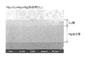
- FIG. 2 is a focused ion beam scanning electron microscope (FIB-SEM) image of a metal laminate according to Example 1.
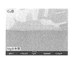
- FIG. 2 is a focused ion beam scanning electron microscope (FIB-SEM) image of a metal laminate according to Example 1.
- FIG. 2 is a focused ion beam scanning electron microscope (FIB-SEM) image of a metal laminate according to Comparative Example 1.
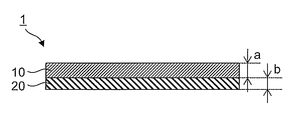
- the metal laminate 1 of the present invention has a two-layer structure in which a magnesium alloy layer 20 is laminated on a copper layer 10 and has no intermetallic compound at the interface.
- intermetallic compounds Mg 2 Cu, Cu 2 Mg, and the like are assumed.
- the metal laminate of FIG. 1 is a high-performance material that exhibits excellent heat dissipation, is lightweight, and has electrical conductivity because it has the properties of copper and magnesium alloy.
- “having no intermetallic compound at the interface” means that the presence or absence of a product at the interface can be confirmed by observing the interface at a magnification of 5000 to 10,000 times. In the present invention, 0.1 ⁇ m or more In this state, no product is formed.
- the difference between fracture in the base metal and interfacial delamination is, for example, in the case where there is a fracture in the base metal in the magnesium alloy layer, the magnesium alloy layer is analyzed when analyzed by Auger electron spectroscopy on the peeled surface on the copper layer side. Judgment can be made by the absence of detection of elements other than those contained (for example, copper).
- a copper plate material or foil can be used as the copper layer 10.
- copper preferably has a high purity in order to further improve heat dissipation, electrical conductivity, etc., specifically 99.0% by mass or more, more preferably 99.5. Although it is more than mass%, it is not limited to this.
- copper foil rolled copper foil, electrolytic copper foil, copper foil by metallization, etc. can be used. When an alloy element is added to copper to obtain a copper alloy, the total content of these additive elements and inevitable impurities is preferably less than 1.0% by mass.
- the thickness of the copper plate or foil is usually 0.01 mm or more, and is applicable from the viewpoint of mechanical strength and workability of the obtained metal laminate.
- the thickness is preferably 0.01 mm to 0.7 mm, but is not limited to this range.
- the “thickness” of the plate material or foil in the present invention can be measured with a micrometer or the like, and means an average value of thicknesses measured at 10 points randomly selected from the entire range of the target material.
- the thickness unevenness is within 10% in all measured values.
- the thickness unevenness value is small.
- a magnesium alloy plate or foil can be used as the magnesium alloy layer 20.
- the magnesium alloy include AZ31, AZ61, AZ91, and LZ91.
- the surface hardness Hv of the magnesium alloy plate or foil is appropriately selected in consideration of the fact that if it is too large, the formability of the metal laminated material after joining is lowered, and conversely if it is too small, handling becomes difficult. Is done.
- 30 ⁇ Hv ⁇ 100 but not limited thereto.
- the thickness of the magnesium alloy plate or foil is usually 0.01 mm or more, and is applicable from the viewpoint of mechanical strength and workability of the obtained metal laminate, and is 0.01 mm to 0.99 mm. Although it is preferable, it is not limited to this range.
- the thickness of the magnesium alloy plate or foil is preferably 0.01 mm to 0.7 mm, and preferably 0.01 mm to 0.5 mm. Is more preferable.
- the thickness unevenness is preferably within 10% in all measured values.
- the thickness of the metal laminate 1 (a + b in FIG. 1) is too thin, handling becomes difficult. On the other hand, if the thickness of the copper layer is too thick, the merit of weight reduction becomes small. When the thickness is large, continuous production from reel to reel becomes difficult, and accordingly, the thickness is set appropriately in consideration of these balances. Specifically, it is preferably 0.03 mm to 1 mm, particularly 0.05 mm to 0.7 mm.
- the thickness ratio (a / (a + b) ⁇ 100) of the copper layer 10 with respect to the entire metal laminate 1 is not particularly limited, but is 5% in order to take advantage of the respective characteristics of the copper layer and the magnesium alloy layer.
- the range of ⁇ 70% is suitable, and the range of 8% ⁇ 50% is particularly preferable.
- the thickness of each layer of a copper layer and a magnesium alloy layer says the average value of the thickness measured in 10 points
- the thickness of each layer can be measured by using, for example, a length measuring function of a focused ion beam scanning electron microscope (FIB-SEM).
- FIB-SEM focused ion beam scanning electron microscope
- K CLAD a Mg ⁇ K Mg + a Cu ⁇ K Cu
- FIG. 2 shows the change in the thermal conductivity improvement magnification accompanying the increase in the ratio.
- the overall thermal conductivity can be improved by increasing the thickness ratio of the copper layer 10.
- the thermal conductivity of the metal laminate 1 is preferably 1.2 times or more, and particularly preferably 1.5 times or more that of the magnesium alloy layer.
- the volume resistivity of the resulting metal laminate can be reduced and electrical conductivity can be imparted.
- the decrease in volume resistivity increases as the thickness ratio of the copper layer increases and can be appropriately designed according to the application.
- the volume resistivity of the metal laminate is 2/3 or less of the magnesium alloy layer. It is preferable that
- the surface of the copper layer 10 and the surface of the magnesium alloy layer 20 on the opposite side of the interface in the metal laminate 1 may have corrosion resistance, oxidation, and so on as long as they do not hinder the intended conductivity and heat dissipation.
- a protective layer can be provided for the purpose of prevention and discoloration prevention.
- the protective layer for the copper layer 10 include a chemical conversion treatment layer and a Ni plating layer.
- the protective layer for the magnesium alloy layer 20 include a metal layer such as copper and aluminum, a chemical conversion treatment layer such as a phosphoric acid type, a chromate type, and an anodizing treatment.
- the magnesium alloy layer is the outermost layer. If it is necessary, there is no need to provide it.
- a copper plate or foil and a magnesium alloy plate or foil are prepared, and these are bonded to each other by various methods such as cold rolling bonding, hot rolling bonding, and surface activation bonding. It can be performed by bonding.
- cold rolling joining if the rolling reduction is increased, the magnesium alloy layer is cracked and joining becomes difficult. Therefore, it is necessary to join under conditions where the magnesium alloy layer does not break.
- stabilization heat processing after joining Hot rolling joining is a method of rolling joining while applying heat above the recrystallization temperature of the joining material, and can be joined with a lower force than cold rolling joining, but generates an intermetallic compound at the joining interface. Easy to do. Therefore, attention should be paid to the selection of the heating temperature and heating time conditions so as not to generate intermetallic compounds.
- Preferred embodiments of the method for producing the metal laminate 1 are as follows. First, a copper plate material or foil (hereinafter, sometimes referred to as “foil”) is sputter etched and a magnesium alloy plate material or foil is sputter etched.
- the metal laminate 1 shown in FIG. 1 can be manufactured by press-contacting the sputter-etched surface of the plate material or foil to form a two-layer structure of copper layer / magnesium alloy layer. This method is preferable because the rolling reduction can be lowered (several percent or less), and the magnesium alloy layer can be joined without cracking even at room temperature.
- a copper foil or a magnesium alloy foil is prepared as a long coil having a width of 100 mm to 600 mm, and copper and magnesium alloy having a joint surface are respectively grounded as one electrode and insulated.
- An alternating current of 1 MHz to 50 MHz is applied to the supported other electrode to generate a glow discharge, and the area of the electrode exposed in the plasma generated by the glow discharge is set to 1 of the area of the other electrode. / 3 or less.
- the grounded electrode is in the form of a cooling roll to prevent the temperature of each conveying material from rising.
- the adsorbed material on the surface is completely removed by sputtering the surface where the copper and magnesium alloy are joined with an inert gas under vacuum, and part or all of the oxide layer on the surface is removed.
- a magnesium alloy it is not always necessary to completely remove the oxide layer, and a sufficient bonding force can be obtained even in a partially remaining state.
- the sputter etching processing time can be greatly reduced as compared with the case where the oxide layer is completely removed, and the productivity of the metal laminate can be improved.
- the inert gas argon, neon, xenon, krypton, or a mixed gas containing at least one of these can be used.
- the adsorbate on the surface can be completely removed with an etching amount of about 1 nm, and the copper oxide layer can usually be removed with about 5 nm to 12 nm (in terms of SiO 2 ). is there.
- the sputter etching process for copper can be performed under vacuum, for example, with a plasma output of 100 W to 10 kW and a line speed of 0.5 m / min to 30 m / min.
- the degree of vacuum at this time is preferably higher in order to prevent re-adsorption on the surface, but it may be, for example, 1 ⁇ 10 ⁇ 5 Pa to 10 Pa.
- the temperature of copper is preferably kept at room temperature to 150 ° C.
- the sputter etching process for the magnesium alloy can be performed under vacuum, for example, with a plasma output of 100 W to 10 kW and a line speed of 0.5 m / min to 30 m / min.
- the degree of vacuum at this time is preferably higher in order to prevent re-adsorbed substances on the surface, but may be 1 ⁇ 10 ⁇ 5 Pa to 10 Pa.
- the pressure welding between the copper foil or the like and the magnesium alloy foil or the like can be performed by roll pressure welding.
- the rolling line load for roll pressure welding is not particularly limited, and can be set, for example, within a range of 0.1 to 10 tf / cm.
- the temperature at the time of joining by roll pressure welding is not particularly limited, and is, for example, from room temperature to 150 ° C.
- the thickness unevenness tends to deteriorate, so it is preferably 8% or less, more preferably 5% or less.
- the lower limit value of the rolling reduction is 0%.
- Bonding by roll pressure welding is performed in a non-oxidizing atmosphere, for example, an inert gas atmosphere such as Ar, in order to prevent the bonding strength between the two from decreasing due to re-adsorption of oxygen to the copper and magnesium alloy surfaces. preferable.
- a non-oxidizing atmosphere for example, an inert gas atmosphere such as Ar, in order to prevent the bonding strength between the two from decreasing due to re-adsorption of oxygen to the copper and magnesium alloy surfaces.
- the metal laminated material having a two-layer structure obtained by pressure welding is further heat-treated as necessary.
- heat treatment the processing strain of the magnesium alloy layer is removed, and the adhesion between the layers can be improved.
- this heat treatment is carried out at a high temperature for a long time, an intermetallic compound is formed at the interface, and the adhesion (peel strength) tends to be lowered. Therefore, it is necessary to carry out under appropriate conditions. For example, it is preferable to perform heat treatment at 100 ° C. to 200 ° C. for 10 minutes to 6 hours.
- a copper foil having a thickness of 16 ⁇ m, 50 ⁇ m, and 100 ⁇ m, respectively, and AZ31 having a thickness of 44 ⁇ m were used as a magnesium alloy foil.
- the copper foil and the magnesium alloy foil were sputter-etched. Sputter etching for copper foil was performed under conditions of 0.1 Pa and plasma output of 700 W for 20 minutes, and sputter etching for magnesium alloy foil was performed under 0.1 Pa of plasma output of 700 W and 20 minutes. It implemented on condition, and the adsorbate of the surface of copper foil and the foil of a magnesium alloy was removed completely.
- the copper foil after the sputter etching treatment and the magnesium alloy foil were joined by roll pressure welding at a normal temperature and a rolling line load of 1.5 tf / cm to produce a metal laminate having a two-layer structure.
- the rolling reduction of the finally obtained laminated material was calculated by the following formula 1, and was 0% for all the copper foils having thicknesses of 16 ⁇ m, 50 ⁇ m, and 100 ⁇ m. (Sum of thicknesses of test materials ⁇ thickness of laminated materials) / (Sum of thicknesses of test materials) ⁇ 100 (%) Formula (1)
- the volume resistivity ( ⁇ cm) of the obtained metal laminate was measured using a Milliohm HiTester 3540 manufactured by Hioki Electric. The results are shown in Table 1 together with the volume resistivity of the magnesium alloy foil alone. From the results of Table 1, it was found that the volume resistivity can be reduced to 60% or less of the magnesium alloy layer alone by laminating the copper layer on the magnesium alloy layer. Further, it has been clarified that the volume resistivity is as small as that when the thickness ratio of the copper layer is 27% and 53%.
- Example 1 the above metal laminate produced from a copper foil having a thickness of 16 ⁇ m and a magnesium alloy foil having a thickness of 44 ⁇ m was used as Example 1, and this metal laminate was subjected to heat treatment under the conditions shown in Table 2.
- the peel strength 180 ° was measured using a Tensilon universal testing machine RTC-1210A manufactured by Orientec, and the adhesion was examined.
- the results are shown in Table 2 and FIG.
- a focused ion beam scanning electron microscope (FIB-SEM) image (FIB-SEM: JEM-9320FIB manufactured by JEOL Ltd.) of a cross section of the metal laminate of Example 1 (no heat treatment) is shown in FIGS.
- FIG. 6 shows FIB-SEM images of the cross section of the metal laminate material (heat treatment at 300 ° C. for 6 hours).
- FIG. 9 shows an SEM image of the peeled surface of Comparative Example 1 subjected to heat treatment at 300 ° C. for 6 hours
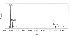
- FIG. 10 shows the EDX analysis result.
- Comparative Example 1 was clearly more uneven on the surface after peeling, and the fracture mode was considered brittle fracture. As shown in FIGS. 8 and 10, only Cu was detected in Example 4, whereas both elements of Cu and Mg were detected in Comparative Example 1. From these observation results, it was considered that the heat treatment at 300 ° C. for 6 hours in Comparative Example 1 produced an intermetallic compound of copper and magnesium at the interface, which caused brittle fracture, resulting in a decrease in peel strength.
- FIG. 11 shows the results measured by etching from the copper layer side in the metal laminate of Example 1. In the measurement by XPS, etching was started after the copper layer was polished to some extent.
- oxygen was not detected in the copper layer, but the detection of oxygen increased with an increase in the detected value of magnesium, and the detection of oxygen decreased as etching progressed from the interface into the magnesium alloy layer. From this, it is considered that the oxide layer on the surface of the copper layer was removed by sputter etching at the time of bonding, and oxygen derived from the oxide layer on the surface of the magnesium alloy layer was detected. It was confirmed that exists at the interface of the metal laminate.
- the thickness of the oxide layer of the magnesium alloy cannot be measured strictly, the thickness of the oxide layer calculated by multiplying the etching rate in terms of SiO 2 in XPS and the etching time was about 2000 nm to 5000 nm.
Landscapes
- Chemical & Material Sciences (AREA)
- Engineering & Computer Science (AREA)
- Materials Engineering (AREA)
- Mechanical Engineering (AREA)
- Metallurgy (AREA)
- Organic Chemistry (AREA)
- Laminated Bodies (AREA)
Abstract
高い放熱性と軽量性を両立させ、さらに電気伝導性をも有するマグネシウム合金を用いた金属積層材を提供することを目的とする。 銅層10/マグネシウム合金層20の2層構造を有し、界面に金属間化合物を有しない金属積層材1である。
Description
本発明は、銅及びマグネシウムからなる金属積層材及びその製造方法に関する。
金属積層材(クラッド材)は、2種以上の異なる金属を互いに貼り合わせた材料であり、単独の材料では得られない複合特性を有する高機能性金属材料である。従来、このような金属積層材は、接合面の洗浄、圧延接合等の各工程を経ることによって製造されている。
金属積層材の例として、ステンレスとアルミニウムの金属積層材が知られている。この金属積層材は、アルミニウムの軽量性及びステンレスの強さの両方の特性を有しており、各々単一の材料と比べ、高い成形加工性及び放熱性を有するため、広く用いられている。
例えば、特許文献1には、外層材をアルミニウム材として、芯材をステンレス鋼からなることを特徴とする3層クラッド構造を有する電子機器用放熱板素材が記載されている。
また、特許文献2には、ステンレス鋼板の一方の表面にAlを主成分とするAl基金属からなる硬質アルミニウム板を接合したクラッド材であって、前記ステンレス鋼板の硬度がHv400以下であり、一方前記硬質アルミニウム板の硬度がHv40以上であり、且つステンレス鋼板と硬質アルミニウム板との接合強度が0.3kgf/cm以上であるアルミニウム・ステンレス鋼クラッド材が記載されている。
しかし、モバイル電子機器等の各種電子機器への応用を考慮すると、電子機器のさらなる高機能化及び軽量化が進んだ場合、ステンレスとアルミニウムの金属積層材では軽量性と放熱性の高いレベルでの両立は困難である。
このような状況下、本発明者らは、金属積層材の構成材料としてマグネシウム合金に注目した。マグネシウム合金は、放熱性に優れ且つ軽量であり、アルミニウムよりも比強度が大きいという利点を有している。しかしながら、マグネシウム合金は、耐食性が悪く、また、すべり面が少ないため方位性があり、特に二軸方向の加工性が極端に低いという問題があるため、マグネシウム合金を用いた金属積層材の従来例はアルミニウムを用いた金属積層材に比べると非常に限られている。
上記マグネシウム合金を用いた金属積層材の例として、特許文献3には、鋼で構成された第1の部材と、マグネシウム合金で構成された第2の部材とを接合する接合方法において、前記第1の部材と前記第2の部材との間に挿入部材を設置する挿入ステップと、前記挿入部材を設置した状態で前記第1の部材と前記第2の部材とを、前記挿入部材が溶融する所定温度まで加熱するステップとを備え、これにより前記第1の部材と前記第2の部材との界面に金属間化合物Fe2Al5を形成する接合方法が開示されている。この接合方法では、挿入部材を別途用いて溶融する温度まで加熱する必要があり、また得られる積層材は厚みが非常に大きく、積層材の用途が構造用部材に限られるという問題点がある。
また、特許文献4には、マグネシウム合金板及び鋼板材から構成され、前記マグネシウム合金板の表面と前記鋼板材の表面の間に1液性熱硬化型接着剤を介在させて積層した状態で、圧力を加えつつ加熱することにより、その1液性熱硬化型接着剤を硬化させた金属合金積層材が記載されている。この例では、接着剤を用いているため放熱性が低下する欠点があり、また、積層材の厚みが薄い範囲では放熱性の低下はより顕著になると予想される。
上記のとおり、金属積層材としてマグネシウム合金を用いたものが検討されているが、従来のマグネシウム合金の積層材はいずれも問題点を有し、なお改良の必要があった。また、電子機器の高機能化において電気伝導性が求められる場合があるが、マグネシウム合金単体では対応できなかった。そこで本発明は、高い放熱性と軽量性を両立させ、さらに電気伝導性をも有するマグネシウム合金を用いた金属積層材及びその製造方法を提供することを目的とする。
本発明者らが鋭意検討を行った結果、マグネシウム合金に対して銅を積層させ、その界面状態を制御することで上記課題が解決されることを見出し、発明を完成した。すなわち、本発明の要旨は次のとおりである。
(1)銅層/マグネシウム合金層の2層構造を有し、界面に金属間化合物を有しない金属積層材。
(2)厚みが0.03mm~1mmである前記(1)に記載の金属積層材。
(3)銅層の厚み比率が、全体の5%~70%である前記(1)又は(2)に記載の金属積層材。
(4)界面にマグネシウム合金の酸化物層が存在する前記(1)~(3)のいずれかに記載の金属積層材。
(5)マグネシウム合金層の熱導電率に対し、1.2倍以上の熱伝導率を有する前記(1)~(4)のいずれかに記載の金属積層材。
(6)マグネシウム合金層の体積抵抗率に対し、2/3以下の体積抵抗率を有する前記(1)~(5)のいずれかに記載の金属積層材。
(7)前記(1)に記載の金属積層材の製造方法であって、
銅の板材もしくは箔をスパッタエッチングする工程と、
マグネシウム合金の板材もしくは箔をスパッタエッチングする工程と、
前記銅及びマグネシウム合金の板材もしくは箔におけるスパッタエッチングした面を圧接し、銅層/マグネシウム合金層の2層構造を形成する工程と、
を含む、前記金属積層材の製造方法。
(8)前記(4)に記載の金属積層材の製造方法であって、
銅の板材もしくは箔をスパッタエッチングし、表面の酸化物層を除去する工程と、
マグネシウム合金の板材もしくは箔を、表面の酸化物層を残存させつつスパッタエッチングする工程と、
前記銅及びマグネシウム合金の板材もしくは箔におけるスパッタエッチングした面を圧接し、銅層/マグネシウム合金層の2層構造を形成する工程と、
を含む、前記金属積層材の製造方法。
(9)前記(7)又は(8)に記載の製造方法によって得られた金属積層材に対し、さらに100℃~200℃で10分~6時間の熱処理を行う工程を含む、金属積層材の製造方法。
(1)銅層/マグネシウム合金層の2層構造を有し、界面に金属間化合物を有しない金属積層材。
(2)厚みが0.03mm~1mmである前記(1)に記載の金属積層材。
(3)銅層の厚み比率が、全体の5%~70%である前記(1)又は(2)に記載の金属積層材。
(4)界面にマグネシウム合金の酸化物層が存在する前記(1)~(3)のいずれかに記載の金属積層材。
(5)マグネシウム合金層の熱導電率に対し、1.2倍以上の熱伝導率を有する前記(1)~(4)のいずれかに記載の金属積層材。
(6)マグネシウム合金層の体積抵抗率に対し、2/3以下の体積抵抗率を有する前記(1)~(5)のいずれかに記載の金属積層材。
(7)前記(1)に記載の金属積層材の製造方法であって、
銅の板材もしくは箔をスパッタエッチングする工程と、
マグネシウム合金の板材もしくは箔をスパッタエッチングする工程と、
前記銅及びマグネシウム合金の板材もしくは箔におけるスパッタエッチングした面を圧接し、銅層/マグネシウム合金層の2層構造を形成する工程と、
を含む、前記金属積層材の製造方法。
(8)前記(4)に記載の金属積層材の製造方法であって、
銅の板材もしくは箔をスパッタエッチングし、表面の酸化物層を除去する工程と、
マグネシウム合金の板材もしくは箔を、表面の酸化物層を残存させつつスパッタエッチングする工程と、
前記銅及びマグネシウム合金の板材もしくは箔におけるスパッタエッチングした面を圧接し、銅層/マグネシウム合金層の2層構造を形成する工程と、
を含む、前記金属積層材の製造方法。
(9)前記(7)又は(8)に記載の製造方法によって得られた金属積層材に対し、さらに100℃~200℃で10分~6時間の熱処理を行う工程を含む、金属積層材の製造方法。
本明細書は本願の優先権の基礎となる日本国特許出願番号2016-108764号の開示内容を包含する。
本発明によれば、実用合金の中で最も軽量であり、且つ比強度の高いマグネシウム合金を用い、それに対して熱伝導性及び電気伝導性に優れる銅を、界面に金属間化合物を有さない状態で積層させることで、優れた軽量性及び放熱性を有し、さらに電気伝導性が付与された金属積層材を得ることができる。このような金属積層材は、マグネシウム合金と銅を表面活性化接合法にて積層させることにより得ることができる。
以下、本発明を詳細に説明する。
図1に示すように、本発明の金属積層材1は、銅層10に、マグネシウム合金層20を積層させた2層構造を有しており、界面に金属間化合物を有しないことを特徴とする。金属間化合物の例として、Mg2Cu、Cu2Mg等が想定される。図1の金属積層材は、銅とマグネシウム合金の性質を併せ持つため、優れた放熱性を示し、且つ軽量であり、また電気伝導性を有する高機能材料である。なお、ここで「界面に金属間化合物を有しない」とは、界面を5000~10000倍で観察することにより、界面の生成物の有無の確認が可能であり、本発明においては0.1μm以上の生成物の形成がない状態である。具体的には、金属積層材をピール強度試験機により銅層とマグネシウム合金層とに引き剥がし、その引き剥がした銅層の面についてエネルギー分散型X線(EDX)分析を行ったとき、その破断が界面剥離である場合に、つまり母材内破断ではない場合に、観測されるマグネシウムの強度が、銅の強度の1000分の1未満であることをもって、「界面に金属間化合物を有しない」状態であるとする。なお、母材の銅合金にマグネシウムが含まれる場合は、銅合金単体のEDX分析結果と比較し、マグネシウム合金層由来のマグネシウム量を特定した上で銅の強度と比較する。また、母材内破断と界面剥離との相違は、例えばマグネシウム合金層内で母材内破断している場合は、銅層側の剥離面においてオージェ電子分光法により分析したときにマグネシウム合金層に含まれる以外の元素(例えば銅)の検出がないことにより判断可能である。
銅層10としては、銅の板材もしくは箔を用いることができる。銅は、金属積層材の用途にもよるが、放熱性や電気伝導性等をより高める場合には純度が高いものが好ましく、具体的には99.0質量%以上、より好ましくは99.5質量%以上であるが、これに限定されるものではない。銅箔としては、圧延銅箔、電解銅箔、メタライズによる銅箔等を用いることができる。銅に合金元素を添加して銅合金とする場合、これらの添加元素と不可避的不純物との合計含有量は1.0質量%未満であることが好ましい。特に、銅に対して、Sn、Mn、Cr、Zn、Zr、Ni、Si、Mg及びAgの群から選ばれる少なくとも1種を合計で200~2000質量ppm添加すると、純銅に比べて伸びが向上するため好ましい。また、銅の板材もしくは箔の厚みは、通常0.01mm以上であれば適用可能であり、得られる金属積層材の機械的強度及び加工性の観点から、0.01mm~0.9mmであることが好ましく、0.01mm~0.7mmであることがより好ましいが、この範囲に限定されるものではない。なお、本発明における板材もしくは箔の「厚み」は、マイクロメータ等によって測定可能であり、対象材料の全範囲からランダムに選択した10点において測定した厚みの平均値をいう。また、用いる銅の板材もしくは箔については、10点の測定値の平均値からのずれ(以下、「厚みムラ」という)が全ての測定値で10%以内であることが好ましい。特に厚みが1mm未満の薄い箔を用いる場合には、厚みムラの値が大きいと放熱性にばらつきが出ることが懸念されるため、厚みムラの値は小さい方が好ましい。
マグネシウム合金層20としては、マグネシウム合金の板材もしくは箔を用いることができる。マグネシウム合金の具体例として、AZ31、AZ61、AZ91、LZ91等を挙げることができる。また、マグネシウム合金の板材もしくは箔の表面硬度Hvは、大き過ぎると接合後の金属積層材の成形加工性が低下し、逆に小さ過ぎるとハンドリングが困難になるため、これらを考慮して適宜選択される。好ましくは30≦Hv≦100であるが、これに限定されるものではない。さらに、マグネシウム合金の板材もしくは箔の厚みは、通常0.01mm以上であれば適用可能であり、得られる金属積層材の機械的強度及び加工性の観点から、0.01mm~0.99mmであることが好ましいが、この範囲に限定されるものではない。なお、金属積層材の厚みを薄くすることが目的である場合は、マグネシウム合金の板材もしくは箔の厚みは0.01mm~0.7mmであることが好ましく、0.01mm~0.5mmであることがより好ましい。厚みムラは、銅層の場合と同様に、全ての測定値で10%以内であることが好ましい。
金属積層材1の厚み(図1におけるa+b)は、薄過ぎるとハンドリング性が困難となり、逆に厚過ぎると、銅層の厚みが厚い場合には軽量化のメリットが小さくなり、マグネシウム合金層の厚みが厚い場合にはリールtoリールでの連続生産が難しくなるため、これらのバランスを考慮して適宜設定される。具体的には、0.03mm~1mm、特に0.05mm~0.7mmであることが好ましい。
また、金属積層材1全体に対する銅層10の厚み比率(a/(a+b)×100)は、特に限定されるものではないが、銅層及びマグネシウム合金層のそれぞれの特性を生かすため、5%~70%の範囲が適当であり、特に8%~50%の範囲であることが好ましい。なお、本発明において、銅層及びマグネシウム合金層の各層の厚みは、対象とする幅1mm×長さ1mの金属積層材の全範囲からランダムに選択した10点において測定した厚みの平均値をいう。なお、各層の厚みの測定は、例えば集束イオンビーム走査電子顕微鏡(FIB-SEM)の測長機能を利用することにより可能である。また、金属積層材の圧下率が0%である場合は、その金属積層材の製造に用いた銅及びマグネシウム合金の板材もしくは箔の厚みを、金属積層材における各層の厚みとしてそのまま利用することができる。
金属積層材1において、マグネシウム合金層及び銅層の厚み比率をそれぞれaMg、aCuとし、マグネシウム合金層及び銅層の熱伝導率をそれぞれKMg、KCuとすると、金属積層材の熱伝導率KCLADは次式により表される。
KCLAD=aMg・KMg+aCu・KCu
KCLAD=aMg・KMg+aCu・KCu
上式に基づき、マグネシウム合金層(AZ31)の厚み比率が100%(すなわち、マグネシウム合金層単体)の熱伝導率を1倍としたときの、マグネシウム合金層の厚み比率の減少(銅層の厚み比率の増加)に伴う熱伝導率向上倍率の変化を図2に示す。図2に示すように、銅層10の厚み比率を増加させることにより、全体の熱伝導率を向上させることができる。電子機器への応用を考慮すると、金属積層材1の熱伝導率は、マグネシウム合金層の熱伝導率の1.2倍以上であることが好ましく、特に好ましくは1.5倍以上である。
また、マグネシウム合金層に対し銅層を積層することで、得られる金属積層材の体積抵抗率を減少させ、電気伝導性を付与することができる。体積抵抗率の減少幅は、銅層の厚み比率が大きい程大きくなり、用途に応じて適宜設計することができるが、特に、金属積層材の体積抵抗率が、マグネシウム合金層の2/3以下であることが好ましい。
さらに、金属積層材1における界面とは反対側の銅層10の面及びマグネシウム合金層20の面には、必要に応じて、目的となる導電性、放熱性を妨げない程度に、耐食性、酸化防止、変色防止等を目的として保護層を設けることができる。銅層10に対する保護層の例としては、化成処理層、Niめっき層等を挙げることができる。また、マグネシウム合金層20に対する保護層の例としては、銅やアルミニウム等の金属層、リン酸系、クロメート系、陽極酸化処理といった化成処理層を挙げることができるが、マグネシウム合金層が最表層にあることが必要な場合には設ける必要はない。
金属積層材1を製造するに際しては、銅の板材もしくは箔と、マグネシウム合金の板材もしくは箔を準備し、これらを冷間圧延接合、熱間圧延接合、表面活性化接合等の各種の方法により互いに接合して行うことができる。冷間圧延接合の場合、圧下率を高くするとマグネシウム合金層が割れて接合が困難になるため、マグネシウム合金層が割れない条件下で接合することが必要である。また、接合した後には安定化熱処理を施すことが好ましい。熱間圧延接合は、接合材の再結晶温度以上の熱を加えながら圧延接合する方法であり、冷間圧延接合に比べて低い力で接合することができるが、接合界面に金属間化合物を生成し易い。したがって、金属間化合物を生成しないよう、加熱温度、加熱時間の条件の選択に留意するものとする。
金属積層材1を製造する方法として好ましい態様は次のとおりである。まず、銅の板材もしくは箔(以下、「箔等」という場合がある)をスパッタエッチングする工程と、マグネシウム合金の板材もしくは箔をスパッタエッチングする工程とを経て、銅の板材もしくは箔及びマグネシウム合金の板材もしくは箔におけるスパッタエッチングした面を圧接し、銅層/マグネシウム合金層の2層構造を形成することにより図1に示す金属積層材1を製造することができる。この方法は、圧下率を低くすることができ(数%以下)、常温でもマグネシウム合金層が割れることなく接合することが可能であるため好ましい。
スパッタエッチング処理は、例えば、銅の箔等及びマグネシウム合金の箔等を、幅100mm~600mmの長尺コイルとして用意し、接合面を有する銅とマグネシウム合金をそれぞれアース接地した一方の電極とし、絶縁支持された他の電極との間に1MHz~50MHzの交流を印加してグロー放電を発生させ、且つグロー放電によって生じたプラズマ中に露出される電極の面積を前記の他の電極の面積の1/3以下として行うことができる。スパッタエッチング処理中は、アース接地した電極が冷却ロールの形をとっており、各搬送材の温度上昇を防いでいる。
スパッタエッチング処理では、真空下で銅とマグネシウム合金の接合する面を不活性ガスによりスパッタすることにより、表面の吸着物を完全に除去し、且つ表面の酸化物層の一部又は全部を除去する。マグネシウム合金の場合は特に、酸化物層は必ずしも完全に除去する必要はなく、一部残存した状態であっても十分な接合力を得ることができる。酸化物層を残存させつつスパッタエッチングを行うことにより、酸化物層を完全に除去する場合に比べてスパッタエッチング処理時間を大幅に減少させ、金属積層材の生産性を向上させることができる。一方、銅の酸化物層は完全に除去することが好ましい。不活性ガスとしては、アルゴン、ネオン、キセノン、クリプトン等や、これらを少なくとも1種類含む混合気体を適用することができる。銅及びマグネシウム合金のいずれについても、表面の吸着物は、エッチング量約1nm程度で完全に除去することができ、銅の酸化物層は通常5nm~12nm(SiO2換算)程度で除去が可能である。
銅についてのスパッタエッチング処理は、真空下で、例えば、100W~10kWのプラズマ出力、ライン速度0.5m/分~30m/分で行うことができる。この時の真空度は、表面への再吸着物を防止するため高い方が好ましいが、例えば、1×10-5Pa~10Paであれば良い。スパッタエッチング処理において、銅の温度は、好ましくは常温~150℃に保たれる。
マグネシウム合金についてのスパッタエッチング処理は、真空下で、例えば、100W~10kWのプラズマ出力、ライン速度0.5m/分~30m/分で行うことができる。この時の真空度は、表面への再吸着物を防止するため高い方が好ましいが、1×10-5Pa~10Paであれば良い。
銅の箔等とマグネシウム合金の箔等との圧接は、ロール圧接により行うことができる。ロール圧接の圧延線荷重は、特に限定されずに、例えば、0.1~10tf/cmの範囲に設定して行うことができる。またロール圧接による接合時の温度は、特に限定されずに、例えば、常温~150℃である。
圧接する際の圧下率は、10%を超えると厚みムラが悪くなる傾向があるため、好ましくは8%以下、さらに好ましくは5%以下である。なお、圧接の前後で厚さは変わらなくても良いため、圧下率の下限値は0%である。
ロール圧接による接合は、銅とマグネシウム合金表面への酸素の再吸着によって両者間の接合強度が低下するのを防止するため、非酸化雰囲気中、例えばAr等の不活性ガス雰囲気中で行うことが好ましい。
圧接により得られた2層構造を有する金属積層材は、必要に応じて、さらに熱処理を行うことが好ましい。熱処理によって、マグネシウム合金層の加工ひずみが除かれ、層間の密着性を向上させることができる。この熱処理は、高温で長時間行うと、界面に金属間化合物を生成し、密着性(ピール強度)が低下する傾向があるため、適切な条件下で行う必要がある。例えば、100℃~200℃で10分~6時間の熱処理を行うことが好ましい。
以上の工程により2層構造の金属積層材を得ることができる。
以下、実施例及び比較例に基づき本発明をさらに詳細に説明するが、本発明はこれらの実施例に限定されるものではない。
(体積抵抗率調査)
厚みがそれぞれ16μm、50μm及び100μmの銅箔と、マグネシウム合金の箔として厚み44μmのAZ31を用いた。これらを圧接するにあたり、銅箔とマグネシウム合金の箔に対してスパッタエッチング処理を施した。銅箔についてのスパッタエッチングは、0.1Pa下で、プラズマ出力700W、20分間の条件にて実施し、マグネシウム合金の箔についてのスパッタエッチングは、0.1Pa下で、プラズマ出力700W、20分間の条件にて実施し、銅箔及びマグネシウム合金の箔の表面の吸着物を完全に除去した。スパッタエッチング処理後の銅箔とマグネシウム合金の箔とを、常温で、圧延線荷重1.5tf/cmにてロール圧接により接合して2層構造を有する金属積層材を製造した。最終的に得られた積層材の圧下率は下記式1により算出され、厚みが16μm、50μm及び100μmの銅箔を用いたものについて全て0%であった。
(供試材の各厚みの総和-積層材の厚み)/(供試材の各厚みの総和)×100(%)・・・式(1)
厚みがそれぞれ16μm、50μm及び100μmの銅箔と、マグネシウム合金の箔として厚み44μmのAZ31を用いた。これらを圧接するにあたり、銅箔とマグネシウム合金の箔に対してスパッタエッチング処理を施した。銅箔についてのスパッタエッチングは、0.1Pa下で、プラズマ出力700W、20分間の条件にて実施し、マグネシウム合金の箔についてのスパッタエッチングは、0.1Pa下で、プラズマ出力700W、20分間の条件にて実施し、銅箔及びマグネシウム合金の箔の表面の吸着物を完全に除去した。スパッタエッチング処理後の銅箔とマグネシウム合金の箔とを、常温で、圧延線荷重1.5tf/cmにてロール圧接により接合して2層構造を有する金属積層材を製造した。最終的に得られた積層材の圧下率は下記式1により算出され、厚みが16μm、50μm及び100μmの銅箔を用いたものについて全て0%であった。
(供試材の各厚みの総和-積層材の厚み)/(供試材の各厚みの総和)×100(%)・・・式(1)
得られた金属積層材について、日置電機製ミリオームハイテスタ3540を用いて体積抵抗率(μΩcm)を測定した。その結果を、マグネシウム合金の箔単体の体積抵抗率とともに表1に示す。表1の結果から、マグネシウム合金層に対し銅層を積層させることで、体積抵抗率をマグネシウム合金層単体の60%以下にできることが分かった。また、銅層の厚み比率が27%の場合と53%の場合とでは、体積抵抗率は同程度に小さいことが明らかとなった。

(熱処理による影響調査)
次に、厚み16μmの銅箔と厚み44μmのマグネシウム合金の箔から製造した上記の金属積層材を実施例1として、この金属積層材に対し表2に示す各条件で熱処理を施した。熱処理後、オリエンテック製テンシロン万能試験機RTC-1210Aを用いて、ピール強度(180°)を測定し密着性を調べた。その結果を表2及び図3に示す。また、実施例1(熱処理なし)の金属積層材の断面の集束イオンビーム走査電子顕微鏡(FIB-SEM)像(FIB-SEM:日本電子製JEM-9320FIB)を図4及び5に、比較例1(300℃×6時間の熱処理)の金属積層材の断面のFIB-SEM像を図6にそれぞれ示す。
次に、厚み16μmの銅箔と厚み44μmのマグネシウム合金の箔から製造した上記の金属積層材を実施例1として、この金属積層材に対し表2に示す各条件で熱処理を施した。熱処理後、オリエンテック製テンシロン万能試験機RTC-1210Aを用いて、ピール強度(180°)を測定し密着性を調べた。その結果を表2及び図3に示す。また、実施例1(熱処理なし)の金属積層材の断面の集束イオンビーム走査電子顕微鏡(FIB-SEM)像(FIB-SEM:日本電子製JEM-9320FIB)を図4及び5に、比較例1(300℃×6時間の熱処理)の金属積層材の断面のFIB-SEM像を図6にそれぞれ示す。

図4及び5に示すように、熱処理を行わない実施例1の金属積層材においては、銅層とマグネシウム合金層との界面に生成物は確認されなかった。一方、300℃で6時間の熱処理を行った比較例1の金属積層材では、図6に示すように界面において厚み0.1μm以上の生成物層が観測された。また、比較例1の金属積層材は、図3に示すように、熱処理を行わない実施例1の金属積層材に比べてピール強度が低下した。この結果は、300℃、6時間の熱処理によって現れる界面の生成物層によるものと考えられる。
次に、100℃で6時間の熱処理を行った実施例4の金属積層材について、ピール試験後の銅層側の剥離面のSEM観察を行った(SEM:日立ハイテクノロジーズ製SU8020)。その結果を図7に示す。また、その剥離面についてエネルギー分散型X線(EDX)分析を行った(EDX:AMETEK製OCTANE SUPER)。その結果を図8に示す。同様にして、300℃で6時間の熱処理を行った比較例1の剥離面のSEM像を図9に、EDX分析結果を図10にそれぞれ示す。
実施例4(図7)と比較例1(図9)では剥離後の表面において比較例1の方が明らかに凹凸が大きく、破壊形態は脆性破壊と考えられた。また、図8及び図10に示すように、実施例4ではCuのみが検出されたのに対し、比較例1ではCu及びMgの両元素が検出された。これらの観察結果から、比較例1の300℃×6時間の熱処理では、界面に銅とマグネシウムの金属間化合物が生成し、これにより脆性破壊が生じるためピール強度が低下するものと考えられた。
(酸化物層の測定)
金属積層材の界面における酸化物層について、XPS(X線光電子分光)(アルバックファイ社製PHI5000VersaProbeII)を用いて確認した。
金属積層材の界面における酸化物層について、XPS(X線光電子分光)(アルバックファイ社製PHI5000VersaProbeII)を用いて確認した。
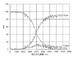
図11は、実施例1の金属積層材において、銅層側からエッチングを行い測定したものである。なお、XPSでの測定にあたっては、銅層をある程度研磨した後にエッチングを開始した。
図11に示すように、銅層内では酸素は検出されないが、マグネシウムの検出値増加とともに酸素の検出も増加し、界面からマグネシウム合金層内へとエッチングが進むと酸素の検出が減少した。このことから、銅層表面の酸化物層は接合時のスパッタエッチングにより除去されており、マグネシウム合金層表面の酸化物層に由来する酸素が検出されたものと考えられ、マグネシウム合金の酸化物層が金属積層材の界面に存在することが確認された。
マグネシウム合金の酸化物層の厚みは、厳密には測定できないが、XPSにおいてエッチングレートをSiO2換算として、エッチング時間とかけあわせて算出される酸化物層の厚みは2000nm~5000nm程度であった。
1 金属積層材
10 銅層
20 マグネシウム合金層
10 銅層
20 マグネシウム合金層
本明細書で引用した全ての刊行物、特許及び特許出願はそのまま引用により本明細書に組み入れられるものとする。
Claims (9)
- 銅層/マグネシウム合金層の2層構造を有し、界面に金属間化合物を有しない金属積層材。
- 厚みが0.03mm~1mmである請求項1に記載の金属積層材。
- 銅層の厚み比率が、全体の5%~70%である請求項1又は2に記載の金属積層材。
- 界面にマグネシウム合金の酸化物層が存在する請求項1~3のいずれかに記載の金属積層材。
- マグネシウム合金層の熱導電率に対し、1.2倍以上の熱伝導率を有する請求項1~4のいずれかに記載の金属積層材。
- マグネシウム合金層の体積抵抗率に対し、2/3以下の体積抵抗率を有する請求項1~5のいずれかに記載の金属積層材。
- 請求項1に記載の金属積層材の製造方法であって、
銅の板材もしくは箔をスパッタエッチングする工程と、
マグネシウム合金の板材もしくは箔をスパッタエッチングする工程と、
前記銅及びマグネシウム合金の板材もしくは箔におけるスパッタエッチングした面を圧接し、銅層/マグネシウム合金層の2層構造を形成する工程と、
を含む、前記金属積層材の製造方法。 - 請求項4に記載の金属積層材の製造方法であって、
銅の板材もしくは箔をスパッタエッチングし、表面の酸化物層を除去する工程と、
マグネシウム合金の板材もしくは箔を、表面の酸化物層を残存させつつスパッタエッチングする工程と、
前記銅及びマグネシウム合金の板材もしくは箔におけるスパッタエッチングした面を圧接し、銅層/マグネシウム合金層の2層構造を形成する工程と、
を含む、前記金属積層材の製造方法。 - 請求項7又は8に記載の製造方法によって得られた金属積層材に対し、さらに100℃~200℃で10分~6時間の熱処理を行う工程を含む、金属積層材の製造方法。
Applications Claiming Priority (2)
| Application Number | Priority Date | Filing Date | Title |
|---|---|---|---|
| JP2016108764A JP6813961B2 (ja) | 2016-05-31 | 2016-05-31 | 銅及びマグネシウムからなる金属積層材及びその製造方法 |
| JP2016-108764 | 2016-05-31 |
Publications (1)
| Publication Number | Publication Date |
|---|---|
| WO2017209157A1 true WO2017209157A1 (ja) | 2017-12-07 |
Family
ID=60477747
Family Applications (1)
| Application Number | Title | Priority Date | Filing Date |
|---|---|---|---|
| PCT/JP2017/020174 Ceased WO2017209157A1 (ja) | 2016-05-31 | 2017-05-31 | 銅及びマグネシウムからなる金属積層材及びその製造方法 |
Country Status (2)
| Country | Link |
|---|---|
| JP (1) | JP6813961B2 (ja) |
| WO (1) | WO2017209157A1 (ja) |
Families Citing this family (1)
| Publication number | Priority date | Publication date | Assignee | Title |
|---|---|---|---|---|
| JP7042645B2 (ja) * | 2018-02-15 | 2022-03-28 | 東京特殊電線株式会社 | 銅被覆マグネシウム線、その絶縁電線及び複合電線 |
Citations (6)
| Publication number | Priority date | Publication date | Assignee | Title |
|---|---|---|---|---|
| JPS6126770A (ja) * | 1984-07-16 | 1986-02-06 | Tanaka Kikinzoku Kogyo Kk | Mg,Mg合金,A1,A1合金上へのAu,Ag,Cuのコ−テイング方法 |
| JPH01224184A (ja) * | 1988-03-02 | 1989-09-07 | Toyo Kohan Co Ltd | クラッド金属板の製造法及びその装置 |
| JP2002225174A (ja) * | 2001-01-30 | 2002-08-14 | Mitsui Mining & Smelting Co Ltd | マグネシウム成形品 |
| US20120094146A1 (en) * | 2010-07-19 | 2012-04-19 | Michael David Hardy | Metallic Composite Material |
| JP2015196178A (ja) * | 2014-04-01 | 2015-11-09 | 東洋鋼鈑株式会社 | 金属積層材の製造方法 |
| JP2016076491A (ja) * | 2014-10-07 | 2016-05-12 | ジャパンファインスチール株式会社 | 通信用クラッドワイヤおよびコード |
-
2016
- 2016-05-31 JP JP2016108764A patent/JP6813961B2/ja active Active
-
2017
- 2017-05-31 WO PCT/JP2017/020174 patent/WO2017209157A1/ja not_active Ceased
Patent Citations (6)
| Publication number | Priority date | Publication date | Assignee | Title |
|---|---|---|---|---|
| JPS6126770A (ja) * | 1984-07-16 | 1986-02-06 | Tanaka Kikinzoku Kogyo Kk | Mg,Mg合金,A1,A1合金上へのAu,Ag,Cuのコ−テイング方法 |
| JPH01224184A (ja) * | 1988-03-02 | 1989-09-07 | Toyo Kohan Co Ltd | クラッド金属板の製造法及びその装置 |
| JP2002225174A (ja) * | 2001-01-30 | 2002-08-14 | Mitsui Mining & Smelting Co Ltd | マグネシウム成形品 |
| US20120094146A1 (en) * | 2010-07-19 | 2012-04-19 | Michael David Hardy | Metallic Composite Material |
| JP2015196178A (ja) * | 2014-04-01 | 2015-11-09 | 東洋鋼鈑株式会社 | 金属積層材の製造方法 |
| JP2016076491A (ja) * | 2014-10-07 | 2016-05-12 | ジャパンファインスチール株式会社 | 通信用クラッドワイヤおよびコード |
Also Published As
| Publication number | Publication date |
|---|---|
| JP6813961B2 (ja) | 2021-01-13 |
| JP2017213759A (ja) | 2017-12-07 |
Similar Documents
| Publication | Publication Date | Title |
|---|---|---|
| JP6865172B2 (ja) | 金属積層材及びその製造方法 | |
| JP4961512B2 (ja) | アルミニウム銅クラッド材 | |
| JP6543439B2 (ja) | 金属積層材の製造方法 | |
| JP7085419B2 (ja) | 圧延接合体及びその製造方法 | |
| CN108055835A (zh) | 金属层叠材料及其制造方法 | |
| TWI504767B (zh) | Sputtering target - support plate joint and its manufacturing method | |
| JP7116870B2 (ja) | 銅合金板、めっき皮膜付銅合金板及びこれらの製造方法 | |
| JP6364910B2 (ja) | クラッド材およびクラッド材の製造方法 | |
| KR101568710B1 (ko) | 구리층을 갖는 철계부스바 및 상기 철계부스바 제조방법 | |
| JP6637200B2 (ja) | 圧延接合体及びその製造方法 | |
| JP7475328B2 (ja) | アルミニウム合金箔、積層体、アルミニウム合金箔の製造方法、および積層体の製造方法 | |
| JP6813961B2 (ja) | 銅及びマグネシウムからなる金属積層材及びその製造方法 | |
| WO2017115661A1 (ja) | クラッド材および電子機器用筐体 | |
| CN112020406B (zh) | 轧制接合体及轧制接合体的制造方法 | |
| CN113316655B (zh) | 铜合金板、带镀膜的铜合金板及它们的制造方法 | |
| WO2021025071A1 (ja) | 銅合金板、めっき皮膜付銅合金板及びこれらの製造方法 | |
| JP2012124220A (ja) | リードフレーム用複合材の製造方法 | |
| WO2019176937A1 (ja) | 圧延接合体及びその製造方法 | |
| US20250196472A1 (en) | Roll-bonded laminate and method for producing the same | |
| KR20140102469A (ko) | Cu 및 Al의 확산 및 반응 제어를 통하여 신뢰성이 향상된 Cu/Al 하이브리드 합금소재 및 그 제조방법 | |
| JP5053172B2 (ja) | ボイド発生を抑制する鋼板の製造方法 | |
| JP2010126806A (ja) | 表面処理金属材およびその製造方法 | |
| HK1177716B (en) | Aluminum copper clad material and manufacturing method thereof |
Legal Events
| Date | Code | Title | Description |
|---|---|---|---|
| 121 | Ep: the epo has been informed by wipo that ep was designated in this application |
Ref document number: 17806710 Country of ref document: EP Kind code of ref document: A1 |
|
| NENP | Non-entry into the national phase |
Ref country code: DE |
|
| 122 | Ep: pct application non-entry in european phase |
Ref document number: 17806710 Country of ref document: EP Kind code of ref document: A1 |