WO2017209110A1 - 電動圧縮機 - Google Patents
電動圧縮機 Download PDFInfo
- Publication number
- WO2017209110A1 WO2017209110A1 PCT/JP2017/020045 JP2017020045W WO2017209110A1 WO 2017209110 A1 WO2017209110 A1 WO 2017209110A1 JP 2017020045 W JP2017020045 W JP 2017020045W WO 2017209110 A1 WO2017209110 A1 WO 2017209110A1
- Authority
- WO
- WIPO (PCT)
- Prior art keywords
- stator
- notches
- housing
- teeth
- yoke
- Prior art date
- Legal status (The legal status is an assumption and is not a legal conclusion. Google has not performed a legal analysis and makes no representation as to the accuracy of the status listed.)
- Ceased
Links
Images


Classifications
-
- F—MECHANICAL ENGINEERING; LIGHTING; HEATING; WEAPONS; BLASTING
- F04—POSITIVE - DISPLACEMENT MACHINES FOR LIQUIDS; PUMPS FOR LIQUIDS OR ELASTIC FLUIDS
- F04B—POSITIVE-DISPLACEMENT MACHINES FOR LIQUIDS; PUMPS
- F04B39/00—Component parts, details, or accessories, of pumps or pumping systems specially adapted for elastic fluids, not otherwise provided for in, or of interest apart from, groups F04B25/00 - F04B37/00
-
- H—ELECTRICITY
- H02—GENERATION; CONVERSION OR DISTRIBUTION OF ELECTRIC POWER
- H02K—DYNAMO-ELECTRIC MACHINES
- H02K1/00—Details of the magnetic circuit
- H02K1/06—Details of the magnetic circuit characterised by the shape, form or construction
- H02K1/12—Stationary parts of the magnetic circuit
-
- H—ELECTRICITY
- H02—GENERATION; CONVERSION OR DISTRIBUTION OF ELECTRIC POWER
- H02K—DYNAMO-ELECTRIC MACHINES
- H02K1/00—Details of the magnetic circuit
- H02K1/06—Details of the magnetic circuit characterised by the shape, form or construction
- H02K1/12—Stationary parts of the magnetic circuit
- H02K1/14—Stator cores with salient poles
-
- H—ELECTRICITY
- H02—GENERATION; CONVERSION OR DISTRIBUTION OF ELECTRIC POWER
- H02K—DYNAMO-ELECTRIC MACHINES
- H02K1/00—Details of the magnetic circuit
- H02K1/06—Details of the magnetic circuit characterised by the shape, form or construction
- H02K1/12—Stationary parts of the magnetic circuit
- H02K1/18—Means for mounting or fastening magnetic stationary parts on to, or to, the stator structures
-
- H—ELECTRICITY
- H02—GENERATION; CONVERSION OR DISTRIBUTION OF ELECTRIC POWER
- H02K—DYNAMO-ELECTRIC MACHINES
- H02K1/00—Details of the magnetic circuit
- H02K1/06—Details of the magnetic circuit characterised by the shape, form or construction
- H02K1/22—Rotating parts of the magnetic circuit
- H02K1/27—Rotor cores with permanent magnets
-
- H—ELECTRICITY
- H02—GENERATION; CONVERSION OR DISTRIBUTION OF ELECTRIC POWER
- H02K—DYNAMO-ELECTRIC MACHINES
- H02K7/00—Arrangements for handling mechanical energy structurally associated with dynamo-electric machines, e.g. structural association with mechanical driving motors or auxiliary dynamo-electric machines
- H02K7/14—Structural association with mechanical loads, e.g. with hand-held machine tools or fans
Definitions
- the present invention relates to an electric compressor provided with a compression mechanism and an electric motor for driving the compression mechanism in a housing, and in particular, an electric compressor having a stator in which a plurality of notches for inserting bolts are formed in an outer peripheral portion.
- an electric compressor having a stator in which a plurality of notches for inserting bolts are formed in an outer peripheral portion.
- the electric compressor is configured by housing a compression mechanism and an electric motor that drives the compression mechanism in a housing.
- the housing is configured by fastening a plurality of housing members arranged in the axial direction with bolts.
- a method may be adopted in which flange portions projecting radially outward are provided on the outer peripheral surfaces of the respective housing members, and the respective flange portions are fastened by bolts.
- the compressor body is enlarged in the radial direction. Therefore, conventionally, a configuration has been proposed in which a plurality of notches for inserting bolts are provided in the axial direction on the outer peripheral surface of the stator of the electric motor arranged in the housing, and the housing members are connected by inserting the bolts there. (See Patent Document 1).
- this patent document discloses that a notch is formed at the center in the circumferential direction of each slot of the stator.
- the portion of the yoke where the notch is formed has a smaller magnetic path cross-sectional area (because the yoke width is smaller), so that the magnetic flux is less likely to pass than the yoke where the notch is not formed.
- the magnetic force generated by the magnetic flux decreases. This causes an imbalance of the magnetic force between the yoke part where the notch is formed and the yoke part where the notch is not formed, and torque fluctuation (magnetism fluctuation) during motor rotation increases, causing vibration and noise.
- torque fluctuation magnetism fluctuation
- the magnetic path cross-sectional area is large in the phase having a large number of notches. Since it becomes smaller, it becomes difficult for the magnetic flux to pass, and the magnetic force generated by the magnetic flux decreases. As a result, magnetic force imbalance occurs between the phases, and torque fluctuation during motor rotation increases, causing vibration and noise.
- the teeth are pulled by the rotating rotor with a magnetic force, and the yoke near the teeth is deformed although it is minute.
- the yoke near the tooth where the notch is formed on the outer peripheral side has a larger deformation amount than the yoke near the tooth where the notch is not formed on the outer peripheral side.
- the present invention has been made in view of such circumstances, and in an electric compressor in which a plurality of notches for inserting bolts are formed on a radially outer peripheral side of a portion of a stator where a yoke tooth is provided.
- the main problem is to reduce vibration and noise resulting from the provision of the notches.
- an electric compressor includes a housing configured by fastening a plurality of housing members in the axial direction with bolts, and a compression mechanism that is provided in the housing and sucks and compresses refrigerant.
- the electric motor is a three-phase AC brushless motor, and includes a stator fixed in the housing, and a rotor fixed to the drive shaft and rotatably disposed on the inner diameter side of the stator,
- the stator is wound around the teeth through a stator core composed of an annular yoke and a plurality of teeth projecting radially inward from the yoke, and a slot formed between the teeth.
- the rotor includes an annular rotor core and a magnet housed inside the rotor core, which form a plurality of magnetic poles on the outer peripheral surface of the rotor,
- the ratio of the number of magnetic poles of the rotor and the number of slots of the stator is 2 to 3
- the plurality of notches are formed on a radially outer side of the yoke where the teeth are provided,
- the number of teeth around which the W-phase coil is wound are equal to each other (claim 1).
- the notches are arranged so that the number is equal to each of the three phases. It is possible to avoid the magnetic force imbalance between the phases caused by the difference in the magnetic path cross-sectional area to suppress the torque fluctuation during the rotation of the electric motor, and to reduce the vibration and noise caused by the torque fluctuation.
- the stator is held by a plurality of axially extending stator holding portions protruding from the inner peripheral surface of the housing, and each of the stator holding portions is interposed between the notches adjacent in the circumferential direction. It is good to provide (Claim 2).
- Teeth with notches formed on the outer periphery are pulled by the rotating rotor with magnetic force, and the nearby yoke tends to deform radially inward, while the yokes between adjacent notches are relatively radially outward.
- the stator holding part for holding the stator is provided between the adjacent notches in the circumferential direction, deformation of the yoke between the adjacent notches in the radial direction can be suppressed and pulled. Further, it is possible to suppress deformation of the yoke in the vicinity of the teeth having notches on the outer peripheral portion inward in the radial direction, and it is possible to reduce vibration and noise due to this deformation.
- the stator holding portion is preferably provided at the center between the notches adjacent in the circumferential direction. (Claim 3)
- the stator holding portion that holds the stator is pressed at the place where the maximum deformation of the yoke in the radial direction between the adjacent notches occurs in the radial direction.
- Deformation can be suppressed more effectively, and by pulling, it is possible to effectively suppress the deformation of the yoke in the vicinity of the teeth that have notches on the outer periphery in the radial direction, reducing vibration and noise caused by this deformation. Is possible.
- the circumferential width of the stator holding portion for holding the stator is larger than the circumferential width of one slot.
- the stator holding portion that holds the stator can be pressed with a width at a portion where the deformation of the yoke between the adjacent notches in the radial direction is caused with a width.
- the deformation of the yoke can be more effectively suppressed, and the deformation of the yoke in the vicinity of the teeth having notches on the outer peripheral portion can be effectively suppressed, and the vibration and noise caused by this deformation can be suppressed. Can be reduced.
- the number of slots in the stator is 15, and the number of notches is 6, the plurality of notches are between notches adjacent in the circumferential direction.
- the case where the number of slots is 2 and the case where the number of slots is 3 may be arranged alternately (claim 5).
- the plurality of notches are slots between notches adjacent in the circumferential direction. It is good to arrange so that the number becomes two. (Claim 6)
- the plurality of notches are formed on the yoke teeth. Is formed on the outer side in the radial direction of the part where the magnetic layer is provided, and is arranged so that the number of each of the three phases is the same. Therefore, by providing the notch, the magnetic path cross-sectional area of the outer peripheral portion of the tooth is reduced. Even in this case, the magnetic path cross-sectional area of each phase is the same, and torque fluctuation (magnetism fluctuation) during rotation due to magnetic imbalance between phases can be suppressed, and vibration and noise caused by this torque fluctuation can be reduced. It becomes.
- stator is held by a plurality of axially extending stator holding portions projecting from the inner peripheral surface of the housing, and each stator holding portion is provided with a width in the center between notches adjacent in the circumferential direction.
- FIG. 1 is a cross-sectional view showing an example of the overall configuration of an electric compressor according to the present invention.
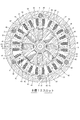
- FIG. 2 is a cross-sectional view taken along the line AA of the electric compressor in FIG. 1 and shows an example of an electric motor having 10 magnetic poles and 15 slots.
- FIG. 3A is a perspective view showing the stator of the electric compressor according to the present invention, and FIG. 3B is a view showing the relationship between the stator and the housing.
- FIG. 4 is a cross-sectional view taken along the line AA of the electric compressor in FIG. 1 and shows an example of an electric motor having 8 magnetic poles and 12 slots.
- an electric compressor 1 is an electric compressor suitable for a refrigeration cycle using a refrigerant as a working fluid
- a compression mechanism 3 is disposed on the right side in the figure in a housing 2 made of an aluminum alloy.
- an electric motor 4 for driving the compression mechanism 3 is disposed on the left side in the drawing.
- the left side in the drawing is the front side of the compressor 1
- the right side in the drawing is the rear side of the compressor 1.
- the compression mechanism 3 employs a scroll type.
- the housing 2 includes a compression mechanism accommodating housing member 5 that accommodates the compression mechanism 3, an electric motor accommodating housing member 6 that accommodates the electric motor 4 that drives the compression mechanism 3, and an inverter that accommodates an inverter device (not shown) that drives and controls the electric motor 4.
- the motor housing housing member 6 and the inverter housing housing member 7 are fastened in the axial direction by fastening bolts 8, and the motor housing housing member 6 and the compression mechanism housing housing member 5 are fastened.
- the bolt 9 is fastened in the axial direction.
- Compression mechanism housing member 5 is formed in a bottomed cylindrical shape that fixes a fixed scroll of a compression mechanism, which will be described later, and is open on the side facing motor housing housing 6.
- the electric motor housing member 6 is provided on the side facing the cylindrical motor fixing portion 6a to which the electric motor 4 is fixed and the compression mechanism housing member 5, and the axial load of the swing scroll 22 of the compression mechanism 3 to be described later.
- an end plate 6b provided integrally with the shaft support portion 10 are integrally formed.
- the inverter housing member 7 includes an inverter housing 7 a and an end plate 7 b in which the shaft support 11 is integrally formed on the side facing the motor housing 6.
- a drive shaft 14 is rotatably supported via bearings 12 and 13 on the shaft support portion 10 of the end plate 6b of the motor housing housing member 6 and the shaft support portion 11 of the end plate 7b of the inverter housing housing member 7. .
- a compression mechanism accommodating portion 15a in which the inside of the housing 2 accommodates the compression mechanism 3 from the rear by the respective end plates 6b, 7b formed in the electric motor accommodating housing member 6 and the inverter accommodating housing member 7, and a motor for accommodating the electric motor 4. It is partitioned into a housing portion 15b and an inverter housing portion 15c that houses the inverter device.
- the inverter accommodating portion 15c is defined by fixing the lid 16 to the inverter accommodating housing member 7 with a bolt or the like (not shown).
- the compression mechanism 3 is of a scroll type having a fixed scroll 21 and an orbiting scroll 22 disposed so as to face the fixed scroll 21.
- the fixed scroll 21 is arranged in the axial direction with respect to the housing 2 (compression mechanism housing member 5). While the movement is permitted, the movement in the radial direction is restricted by the positioning pin 23 with respect to the end plate 6b of the electric motor housing housing member 6, and the disk-like board 21a and the outer edge of the board 21a are all moved.
- a cylindrical outer peripheral wall 21b that is provided over the circumference and is erected forward, and a spiral spiral wall 21c that extends forward from the substrate 21a inside the outer peripheral wall 21b. It is configured.
- the orbiting scroll 22 includes a disc-shaped substrate 22a and a spiral-shaped spiral wall 22c erected rearward from the substrate 22a, and is provided at the center of the back surface of the substrate 22a.
- An eccentric shaft 25 provided eccentrically with respect to the shaft center of the drive shaft 14 at the rear end portion of the drive shaft 14 is supported in the hole 24 via a radial bearing 27, and swivels around the shaft center of the drive shaft 14. It is provided as possible.
- the fixed scroll 21 and the orbiting scroll 22 mesh with each of the spiral walls 21c and 22c, and are surrounded by the substrate 21a and the spiral wall 21c of the fixed scroll 21, and the substrate 22a and the spiral wall 22c of the orbiting scroll 22.
- a compression chamber 26 is defined by the space.
- the rotation prevention mechanism of the orbiting scroll 22 employs, for example, a pin & ring coupling, a plurality of pins 17 arranged in the circumferential direction, and a plurality of rings engaged with the pins 17. It comprises a member 18 and a plurality of cylindrical notches 19 that accommodate the respective ring members 18.
- the shaft support portion 10 formed integrally with the end plate 6 b of the motor housing housing member 6 has a through hole 10 a in the center, and a bearing housing portion in which the bearing 12 is housed from the front side farthest from the swing scroll 22. 31 and a weight accommodating portion 33 for accommodating a balance weight 32 that rotates integrally with the drive shaft 14 are formed.
- a suction chamber 35 for sucking refrigerant is formed between the outer peripheral wall 21b of the fixed scroll 21 and the outermost peripheral portion of the spiral wall 22c of the swing scroll 22 described above. Further, a suction port 38 for sucking refrigerant gas into the motor housing portion 15b is formed on the side surface of the housing 2 (the motor housing housing member 6), and a gap between the stator 40 and the housing 2 (the motor housing housing member 6). In addition, a suction path (not shown) that guides the refrigerant flowing from the suction port 38 to the motor accommodating portion 15b to the suction chamber 35 through a hole (not shown) formed in the end plate 6b is formed.
- a discharge chamber 37 in which the refrigerant gas compressed in the compression chamber 26 is discharged through a discharge hole 36 formed substantially at the center of the fixed scroll 21. It is defined between the rear end wall of the member 5. The refrigerant gas discharged into the discharge chamber 37 is pumped to the external refrigerant circuit through the discharge port 39.
- stator 40 and the rotor 50 constituting the electric motor 4 are accommodated in a portion of the electric motor accommodating housing member 6 in front of the end plate 6 b.
- the stator 40 includes an annular (cylindrical) yoke 42 and a plurality of teeth 43 that protrude radially inward from the yoke 42 and are disposed at equal intervals in the circumferential direction. And a coil 45 corresponding to each of the three phases wound around the teeth 43 through slots 44 formed between the teeth.
- the rotor 50 includes a rotor core 51 fixed to the drive shaft 14 and a permanent magnet 52 housed in the rotor core 51, which form a plurality of magnetic poles on the outer peripheral surface.
- the rotor core 51 is formed by laminating a large number of electromagnetic steel plates.
- the rotor core 51 is formed with a through-hole 53 for inserting and fixing the drive shaft 14 in the center, and a space 54 for storing the permanent magnet 52 is formed.
- a plurality of holes are formed around the through hole 53 at equal intervals on the circumference.
- These through-holes 53 and spaces 54 extend in the laminating direction of the electromagnetic steel plates, and the permanent magnets 52 are held inside the rotor core 51 in a state of being accommodated in the spaces 54, and a plurality of magnetic poles are formed on the outer peripheral surface of the rotor.
- the number of magnetic poles of the rotor 50 is 10, and the number of slots of the stator 40 is 15.
- a plurality of notches 46 for inserting the fastening bolts 8 are extended in the axial direction on the outer peripheral surface of the stator 40 (the outer peripheral surface of the yoke 42).
- the notches 46 are provided at six locations, and each notch 46 is formed on the outer side in the radial direction of the portion where the teeth 43 of the yoke 42 are provided, and the notches 46 are provided on the outer peripheral portion.
- the magnetic path cross-sectional area of the connection portion with the yoke 42 is smaller than the magnetic path cross-sectional area of the connection portion with the yoke 42 of the teeth 43 that do not have the notch 46 on the outer peripheral portion.
- the number of the six cutouts 46 is arranged to be the same number in each of the three phases. That is, of the teeth 43 having notches 46 on the outer peripheral portion, the number of teeth around which a U-phase coil is wound (hereinafter referred to as U-phase teeth), the teeth around which a V-phase coil is wound ( 6 notches so that the number of V-phase teeth (hereinafter referred to as V-phase teeth) and the number of W-phase coil-wrapped teeth (hereinafter referred to as W-phase teeth) are the same number (2 each). 46 is arranged.
- the six notches 46 are arranged so that the number of slots between adjacent notches in the circumferential direction is 2 and the case of 3 Has been. Therefore, with reference to the upper right portion where the notch is formed on the outer peripheral portion of the U-phase tooth, the W-phase tooth that is 2 slots clockwise from the notch and the 3-second slot away from the W-phase tooth. W-phase teeth, V-phase teeth 2 slots away from the W-phase teeth, V-phase teeth 3 slots away from the V-phase teeth, and U-phase teeth 2 slots away from the V-phase teeth A notch 46 is formed in each of the outer peripheral portions.
- the stator 40 is fixed to the housing 2 (electric motor housing member 6) by a plurality of stators extending along the axial direction of the drive shaft 14 on the inner peripheral surface of the housing 2 (motor housing member 6). This is done by pressing the holding portion 61 at a location avoiding the notch 46 on the outer peripheral surface of the stator 40 (the outer peripheral surface of the yoke 42).
- the stator holding portion 61 is configured such that the inner peripheral wall of the housing 2 (the motor housing housing member 6) bulges inward so as to contact the outer peripheral surface of the yoke 42 with a predetermined circumferential width. Six locations are formed in the circumferential direction on the inner peripheral surface of the motor housing member 6). Therefore, a stator non-holding portion 62 that does not contact the stator 40 is formed between the adjacent stator holding portions 61.
- the diameters of the inscribed circles of the plurality of stator holding portions 61 are formed slightly smaller than the outer diameter of the yoke 42 (the outer diameter of the yoke 42 is smaller than the diameter of the inscribed circle of the stator holding portion 61 of the housing 2).
- the housing 2 is heated to a high temperature and thermally expanded, and a stator 40 having a normal temperature is inserted into the housing 2 until the insertion end of the yoke 42 contacts the stepped portion 28 of the housing 2.
- the stator 2 is compressed and fixed to the stator holding portion 61 by returning the housing 2 to normal temperature and contracting it.
- stator holding portion 61 is provided so as to abut on the central portion between the notches 46 adjacent in the circumferential direction of the yoke 42, and therefore, on the inner circumferential surface of the housing 2 (the motor housing member 6) in the circumferential direction. Are arranged at equal intervals.
- stator holding portion 61 is provided so as to be held with a width wider than the yoke outer peripheral surface corresponding to the slot width. That is, as shown in FIG. 3B, the circumferential width A of the stator holding portion 61 holding the stator 40 is set larger than the circumferential width B of one slot, and the stator holding portion 61
- the circumferential range is configured so that it can be held with a width at the center between notches adjacent in the circumferential direction with a large amount of deformation in the outer diameter direction.
- the yoke 42 portion in which the notch 46 is formed in the outer peripheral portion is pulled by the rotor 50 (pulled inward in the radial direction) compared to the yoke 42 in which the notch 46 is not in the outer peripheral portion. 42 is about to deform, and accordingly, the yoke part 42 without a notch in the middle part between the notch 46 and the notch 46 tries to deform radially outward. Since the intermediate and central portions are held in close contact with the stator holding portion 61 with a sufficient width, deformation to the outside in the radial direction is prevented, and as a result, the yoke 42 portion in which the notch 46 is formed. It is possible to suppress deformation inward in the radial direction. As a result, it is possible to avoid the disadvantage that the amount of deformation inward of the yoke portion 42 in the vicinity of the teeth 43 having the notch in the outer peripheral portion is increased, and it is possible to reduce vibration and noise.
- the holding portion 61 is illustrated as a bilaterally symmetric shape with the middle and center between the notches 46 and 46 being the center, but is the maximum deformed portion on the radially outer side of the yoke portion 42. It suffices if the center between the notches 46 can be pressed, and a left-right asymmetric shape may be used.
- the six notches 46 are arranged so that the number of slots between the notches 46 adjacent in the circumferential direction is 2, and the notches formed in the U-phase teeth and the V-phase teeth are formed. And two notches formed in the W-phase teeth (the U-phase teeth with the notches formed in the outer periphery and the V-phase teeth with the notches formed in the outer periphery). 2 each of teeth and W-phase teeth with notches formed on the outer periphery), and the stator holding portion 61 is provided in the center between adjacent notches in the circumferential direction, and the notches are formed on the outer periphery.
- the notch 46 is not formed unevenly in the teeth 43 of a certain phase, so that the magnetic force imbalance between the phases is avoided and the torque fluctuation (magnetic force fluctuation) during motor rotation is large. Can be avoided, and vibration and noise can be reduced. Further, since the notch 46 is not formed on the outer peripheral portion, deformation of the teeth 43 (intermediate portion between the adjacent notches 46 on the outer peripheral portion of the stator 40) in the radial direction can be surely suppressed. Therefore, it is possible to avoid the disadvantage that the amount of deformation inwardly of the tooth 43 having the notch 46 is increased, and it is possible to reduce vibration and noise.
- the compression mechanism is not limited to this and can be applied to all compression mechanisms such as a reciprocating type and a vane rotary type.
Landscapes
- Engineering & Computer Science (AREA)
- Power Engineering (AREA)
- Mechanical Engineering (AREA)
- General Engineering & Computer Science (AREA)
- Compressor (AREA)
- Iron Core Of Rotating Electric Machines (AREA)
- Compressors, Vaccum Pumps And Other Relevant Systems (AREA)
- Applications Or Details Of Rotary Compressors (AREA)
- Connection Of Motors, Electrical Generators, Mechanical Devices, And The Like (AREA)
Abstract
【課題】ステータの外周部にボルトを挿通させる複数の切り欠きが形成されている電動圧縮機において、切り欠きを設けたことに起因する振動や騒音を低減する。三3相交流ブラシレスモータを用いた、ステータ40(ヨーク42)の外周面に締結ボルト8を挿通させるための複数の切り欠き46が軸方向に延設されている電動圧縮機において、複数の切り欠き46を、ステータ40におけるヨーク42のティース43が設けられている部位の径方向外側に形成し、ティースに巻装されたコイルで構成される電流相三3相のうち、各相で同数ずつとなるように配置する。また、ステータ40を保持するハウジングの内周面に突設されたステータ保持部61を周方向で隣り合う切り欠き46間に設ける。
Description
本発明は、ハウジング内に、圧縮機構とこの圧縮機構を駆動する電動機とを備えた電動圧縮機に関し、特に、外周部にボルトを挿通させる複数の切り欠きが形成されたステータを有する電動圧縮機に関する。
電動圧縮機は、ハウジング内に、圧縮機構と、この圧縮機構を駆動する電動機とを収容して構成されるが、ハウジングは、軸方向に配置された複数のハウジング部材をボルトによって締結して構成されている。ハウジング部材同士の締結は、それぞれのハウジング部材の外周面に径方向外側に突出するフランジ部を設け、それぞれのフランジ部をボルトによって締結する方法を採用してもよいが、このような構成においては、圧縮機本体が径方向に大型化する等の不都合がある。
そこで、従来においては、ハウジング内に配された電動機のステータの外周面にボルトを挿通する複数の切り欠きを軸方向に設け、そこにボルトを挿通してハウジング部材同士を接続する構成が提案されている(特許文献1参照)。
そこで、従来においては、ハウジング内に配された電動機のステータの外周面にボルトを挿通する複数の切り欠きを軸方向に設け、そこにボルトを挿通してハウジング部材同士を接続する構成が提案されている(特許文献1参照)。
また、この特許文献においては、ステータのそれぞれのスロットの周方向中央に切り欠きを形成する点が開示されている。
ところで、従来の構成においては、切り欠きが形成されたヨークの部分は磁路断面積が小さくなるので(ヨーク幅が小さくなるので)切り欠きが形成されていないヨークよりも磁束が通りにくくなり、磁束により生じる磁力が低下する。これにより、切り欠きが形成されたヨーク部と切り欠きが形成されていないヨーク部での磁力のアンバランスが生じ、モータ回転中のトルク変動(磁力変動)が大きくなって振動や騒音の原因になる。
また、U相、V相、W相を構成する3相のうち、ある相の切り欠きの数が他の相よりも多く設けられると、切り欠きの数が多い相においては磁路断面積が小さくなるので磁束が通りにくくなり、磁束によって生じる磁力が低下する。これにより、相間で磁力アンバランスが生じ、モータ回転中のトルク変動が大きくなって振動や騒音の原因となる。
また、モータ稼働中において、ティースは回転するロータに磁力で引っ張られてティース近辺のヨーク部が微小ではあるが変形する。この際、切り欠きが外周側に形成されているティース近辺のヨークは、切り欠きが外周側に形成されていないティース近辺のヨークに比べて変形量が大きくなり、この点からも振動や騒音の原因となる。
本発明は、係る事情に鑑みてなされたものであり、ステータにおけるヨークのティースが設けられている部位の径方向外周側にボルトを挿通させる切り欠きが複数形成されている電動圧縮機において、切り欠きを設けたことに起因する振動や騒音を低減させることを主たる課題としている。
上記課題を達成するために、本発明に係る電動圧縮機は、複数のハウジング部材をボルトで軸方向に締結して構成されたハウジングと、前記ハウジング内に設けられ、冷媒を吸入圧縮する圧縮機構と、前記ハウジング内に設けられ、前記圧縮機構に駆動軸を介して動力を伝達する電動機とを備え、
前記電動機は、3相交流ブラシレスモータであり、前記ハウジング内に固定されたステータと、前記駆動軸に固装されて前記ステータの内径側に回転可能に配置されたロータとを具備し、
前記ステータは、環状のヨークと、このヨークから径方向内側に向けて突出する複数のティースとで構成されるステータコアと、前記ティース間に形成されたスロットを介して前記ティースに巻装された3相の各相に対応したコイルとを備え、
前記ロータは、前記ロータの外周面に複数の磁極を構成する、環状のロータコアと前記ロータコア内部に収容されるマグネットとを備え、
前記ロータの磁極数と前記ステータのスロット数との比率が2対3であり、
前記ヨークの外周面に前記ボルトを挿通させるための複数の切り欠きが軸方向に延設されている電動圧縮機において、
前記複数の切り欠きは、前記ヨークの前記ティースが設けられている部位の径方向外側に形成され、
3相の各相で同数ずつとなるように(切り欠きを外周部に有するティースの内、U相のコイルが巻装されているティースの数と、V相のコイルが巻装されているティースの数と、W相のコイルが巻装されているティースの数とがそれぞれ同数ずつとなるように)配置されていることを特徴としている(請求項1)。
前記電動機は、3相交流ブラシレスモータであり、前記ハウジング内に固定されたステータと、前記駆動軸に固装されて前記ステータの内径側に回転可能に配置されたロータとを具備し、
前記ステータは、環状のヨークと、このヨークから径方向内側に向けて突出する複数のティースとで構成されるステータコアと、前記ティース間に形成されたスロットを介して前記ティースに巻装された3相の各相に対応したコイルとを備え、
前記ロータは、前記ロータの外周面に複数の磁極を構成する、環状のロータコアと前記ロータコア内部に収容されるマグネットとを備え、
前記ロータの磁極数と前記ステータのスロット数との比率が2対3であり、
前記ヨークの外周面に前記ボルトを挿通させるための複数の切り欠きが軸方向に延設されている電動圧縮機において、
前記複数の切り欠きは、前記ヨークの前記ティースが設けられている部位の径方向外側に形成され、
3相の各相で同数ずつとなるように(切り欠きを外周部に有するティースの内、U相のコイルが巻装されているティースの数と、V相のコイルが巻装されているティースの数と、W相のコイルが巻装されているティースの数とがそれぞれ同数ずつとなるように)配置されていることを特徴としている(請求項1)。
したがって、ヨークの外周面に設けられる複数の切り欠きをティースが設けられている部位の径方向外側に形成する場合において、3相の各相で同数ずつとなるように切り欠きを配置したので、磁路断面積の差から生じる相間の磁力アンバランスを回避して電動機の回転中のトルク変動を抑えることができ、このトルク変動に起因する振動・騒音を低減することが可能となる。
また、前記ステータは、前記ハウジングの内周面に突設された軸方向に延びる複数のステータ保持部によって保持されており、それぞれの前記ステータ保持部は、周方向で隣り合う前記切り欠き間に設けるとよい(請求項2)。
切り欠きが外周部に形成されたティースが回転するロータに磁力で引っ張られてその近辺のヨークが径方向内側に変形しようとする一方、隣り合う切り欠き間のヨークは相対的に径方向外側へ変形しようとするが、ステータを保持するステータ保持部を周方向で隣り合う切り欠き間に設けるようにしたので、隣り合う切り欠き間のヨークの径方向外側への変形を抑えられ、引いては、切り欠きを外周部に有するティース近辺のヨークの径方向内側への変形を抑えることができ、この変形に起因する振動・騒音を低減することが可能である。
尚、前記ステータ保持部は、周方向で隣り合う前記切り欠き間の中央に設けられていることが望ましい。(請求項3)
これにより、ステータを保持するステータ保持部を、隣り合う切り欠き間のヨークの径方向外側への最大変形が生じる個所で押さえるようにしたので、隣り合う切り欠き間のヨークの径方向外側への変形をより効果的に抑えられ、引いては、切り欠きを外周部に有するティース近辺のヨークの径方向内側への変形を効果的に抑えることができ、この変形に起因する振動・騒音を低減することが可能である。
さらに、前記ステータ保持部の前記ステータを保持する周方向の幅は、1スロット分の周方向幅よりも大きいことが望ましい(請求項4)。
これにより、ステータを保持するステータ保持部を、隣り合う切り欠き間のヨークの径方向外側への変形が生じる部位を幅をもって押さえられるようにしたので、隣り合う切り欠き間のヨークの径方向外側への変形をより効果的に抑えられ、引いては、切り欠きを外周部に有するティース近辺のヨークの径方向内側への変形を効果的に抑えることができ、この変形に起因する振動・騒音を低減することが可能である。
なお、前記ロータの磁極数が10で、前記ステータのスロット数が15であり、前記切り欠きの数が6であるステータにおいて、前記複数の切り欠きは、周方向で隣り合う切り欠きの間のスロット数が2である場合と3である場合とが交互になるように配置するとよい(請求項5)。
このように切り欠きを配置することで、3相の各相に同数ずつ(2つずつ)の切り欠きが設けられることになり、各相の磁路断面積が等しくなるので、相間の磁力アンバランスによるトルク変動を効果的に抑えられ、トルク変動に起因する振動・騒音の抑制が可能となる。
また、前記ロータの磁極数が8で、前記ステータのスロット数が12であり、前記切り欠きの数が6であるステータにおいて、前記複数の切り欠きは、周方向で隣り合う切り欠き間のスロット数が2となるように配置するとよい。(請求項6)
このように切り欠きを配置することで、3相の各相に同数ずつ(2つずつ)の切り欠きが設けられることになり、各相の磁路断面積の総和が等しくなるので、相間の磁力アンバランスによるトルク変動を効果的に抑えられ、トルク変動に起因する振動・騒音を低減することが可能となる。
以上述べたように、本発明によれば、ヨークの外周面にボルトを挿通させるための複数の切り欠きが軸方向に延設されている電動圧縮機において、複数の切り欠きを、ヨークのティースが設けられている部位の径方向外側に形成し、また、3相の各相で同数ずつとなるように配置したので、切り欠きを設けたことでティースの外周部の磁路断面積が小さくなる場合でも各相の磁路断面積は等しくなり、相間の磁力アンバランスによる回転中のトルク変動(磁力変動)を抑えることができ、このトルク変動に起因する振動や騒音を低減することが可能となる。
また、ステータを、ハウジングの内周面に突設された軸方向に延びる複数のステータ保持部によって保持し、それぞれのステータ保持部を、周方向で隣り合う切り欠き間の中央に幅をもって設けるようにすることで、ヨークの隣り合う切り欠き間の部分の径方向外側への変形を抑えることができ、引いては、切り欠きを外周部に有するティース近辺のヨークの径方向内側への変形を抑えることが可能となり、ステータの変形に起因する振動や騒音を低減することが可能となる。
以下、本発明に係る電動圧縮機の構成例について、図面を参照しながら説明する。
図1において、電動圧縮機1は、冷媒を作動流体とする冷凍サイクルに適した電動型圧縮機であり、アルミ合金で構成されたハウジング2内に、図中右方において圧縮機構3を配設し、また、図中左側において前記圧縮機構3を駆動する電動機4を配設している。尚、図1において、図中左側を圧縮機1の前方、図中右側を圧縮機1の後方としている。また、本発明においては、圧縮機構3はスクロール式を採用している。
図1において、電動圧縮機1は、冷媒を作動流体とする冷凍サイクルに適した電動型圧縮機であり、アルミ合金で構成されたハウジング2内に、図中右方において圧縮機構3を配設し、また、図中左側において前記圧縮機構3を駆動する電動機4を配設している。尚、図1において、図中左側を圧縮機1の前方、図中右側を圧縮機1の後方としている。また、本発明においては、圧縮機構3はスクロール式を採用している。
ハウジング2は、圧縮機構3を収容する圧縮機構収容ハウジング部材5と、圧縮機構3を駆動する電動機4を収容する電動機収容ハウジング部材6と、電動機4を駆動制御する図示しないインバータ装置を収容するインバータ収容ハウジング部材7とを有し、電動機収容ハウジング部材6とインバータ収容ハウジング部材7とは締結ボルト8によって軸方向に締結され、また、電動機収容ハウジング部材6と圧縮機構収容ハウジング部材5とは、締結ボルト9によって軸方向に締結されている。
圧縮機構収容ハウジング部材5は、後述する圧縮機構の固定スクロールを固定し、電動機収容ハウジング部材6と対峙する側が開放された有底の筒状形状に形成されている。電動機収容ハウジング部材6は、電動機4が固定される筒状のモータ固定部6aと、圧縮機構収容ハウジング部材5と対峙する側に設けられ、後述する圧縮機構3の揺動スクロール22の軸方向荷重を支持すると共に、軸支部10が一体に設けられたエンドプレート6bとが一体に形成されている。また、インバータ収容ハウジング部材7は、インバータ収容部7aと、電動機収容ハウジング部材6と対峙する側に軸支部11が一体に形成されたエンドプレート7bとが一体に構成されている。
そして、電動機収容ハウジング部材6のエンドプレート6bの軸支部10とインバータ収容ハウジング部材7のエンドプレート7bの軸支部11には、軸受12,13を介して駆動軸14が回転可能に支持されている。この電動機収容ハウジング部材6とインバータ収容ハウジング部材7とに形成されたそれぞれのエンドプレート6b,7bによりハウジング2の内部が後方から圧縮機構3を収納する圧縮機構収容部15a、電動機4を収納するモータ収容部15b、及び、インバータ装置を収容するインバータ収容部15cに仕切られている。
尚、この例において、インバータ収容部15cは、インバータ収容ハウジング部材7に図示しないボルト等によって蓋体16を固定することで画成されている。
尚、この例において、インバータ収容部15cは、インバータ収容ハウジング部材7に図示しないボルト等によって蓋体16を固定することで画成されている。
圧縮機構3は、固定スクロール21とこれに対向配置された揺動スクロール22とを有するスクロールタイプのもので、固定スクロール21は、ハウジング2(圧縮機構収容ハウジング部材5)に対して、軸方向の動きが許容されつつ、電動機収容ハウジング部材6のエンドプレート6bに対して位置決めピン23により径方向への動きが規制されており、円板状の基板21aと、この基板21aの外縁に沿って全周に亘って設けられると共に前方に向かって立設された円筒状の外周壁21bと、その外周壁21bの内側において前記基板21aから前方に向かって延設された渦巻状の渦巻壁21cとから構成されている。
また、揺動スクロール22は、円板状の基板22aと、この基板22aから後方に向かって立設された渦巻状の渦巻壁22cとから構成され、基板22aの背面中央に設けられた嵌合孔24に、駆動軸14の後端部において駆動軸14の軸心に対して偏心して設けられた偏心軸25がラジアル軸受27を介して支持され、駆動軸14の軸心を中心として旋回運動可能に設けられている。
固定スクロール21と揺動スクロール22とは、それぞれの渦巻壁21c、22cを互いに噛み合わせ、固定スクロール21の基板21a及び渦巻壁21cと、揺動スクロール22の基板22a及び渦巻壁22cとによって囲まれた空間によって圧縮室26が画成されている。
なお、この例において、揺動スクロール22の自転防止機構は、例えば、ピン&リングカップリングが採用され、周方向に配設された複数のピン17と、これらピン17に係合する複数のリング部材18と、それぞれのリング部材18を収容する複数の円筒状切り欠き19とで構成されている。
電動機収容ハウジング部材6のエンドプレート6bに一体に形成された軸支部10は、中央に貫通孔10aを有し、揺動スクロール22から最も離れた前方側から、軸受12が収容される軸受収容部31と、駆動軸14と一体をなして回転するバランスウエイト32を収容するウエイト収容部33とが形成されている。
前述した固定スクロール21の外周壁21bと揺動スクロール22の渦巻壁22cの最外周部との間には、冷媒を吸入する吸入室35が形成されている。また、ハウジング2(電動機収容ハウジング部材6)の側面には、モータ収容部15bに冷媒ガスを吸入する吸入口38が形成され、ステータ40とハウジング2(電動機収容ハウジング部材6)との間の隙間や、エンドプレート6bに形成された図示しない孔等を介して、吸入口38からモータ収容部15bに流入した冷媒を前記吸入室35に導く図示しない吸入経路が構成されている。
さらに、ハウジング内の固定スクロール21の背後には、圧縮室26で圧縮された冷媒ガスが固定スクロール21の略中央に形成された吐出孔36を介して吐出される吐出室37が圧縮機構収容ハウジング部材5の後端壁との間に画成されている。この吐出室37に吐出された冷媒ガスは、吐出口39を介して外部冷媒回路へ圧送されるようになっている。
電動機収容ハウジング部材6のエンドプレート6bよりも前方の部分には、図2にも示されるように、電動機4を構成するステータ40とロータ50とが収容されている。
ステータ40は、環状(円筒状)をなすヨーク42と、このヨーク42から径方向内側に向けて突出し、周方向に等間隔に配設された複数のティース43とで構成されるステータコア41と、前記ティース間に形成されたスロット44を介してティース43に巻装された3相の各相に対応したコイル45とを備えている。
また、ロータ50は、外周面に複数の磁極を形成する、駆動軸14に固装されたロータコア51とこのロータコア51の内部に収納された永久磁石52とを備えている。ロータコア51は、多数の電磁鋼板を積層して形成され、このロータコア51には、駆動軸14を挿入固定するための貫通孔53が中央に形成され、また、永久磁石52を収納する空間54が、貫通孔53の周囲に円周上等間隔に複数形成されている。これら貫通孔53や空間54は電磁鋼板の積層方向に延在し、永久磁石52は、前記空間54に収容された状態でロータコア51の内部に保持されており、ロータの外周面に複数の磁極を形成する。
この例において、ロータ50の磁極数は10であり、ステータ40のスロット数は15である。また、ステータ40の外周面(ヨーク42の外周面)には、前記締結ボルト8を挿通させるための切り欠き46が軸方向に複数延設されている。
切り欠き46は、6か所に設けられており、それぞれの切り欠き46は、ヨーク42のティース43が設けられている部位の径方向外側に形成され、この切り欠き46が外周部に設けられているティース43は、ヨーク42との連接部分の磁路断面積は切り欠き46を外周部に有さないティース43のヨーク42との連接部分の磁路断面積よりも小さくなっている。
そして、この6つの切り欠き46の数は、3相の各相で同数ずつとなるように配置されている。即ち、切り欠き46を外周部に有するティース43の内、U相のコイルが巻装されているティース(以下、U相のティースという)の数、V相のコイルが巻装されているティース(以下、V相のティースという)の数、W相のコイル巻装されているティース(以下、W相のティースという)の数がそれぞれ同数ずつ(2つずつ)となるように、6つの切り欠き46が配置されている。
より具体的に図2の構成例について見ると、6つの切り欠き46は、周方向で隣り合う切り欠きの間のスロット数が2である場合と3である場合とが交互になるように配置されている。したがって、切り欠きがU相のティースの外周部に形成されている右上箇所を基準にすると、そこから、時計回りに2スロット離れたW相のティースと、このW相のティースから3スロット離れたW相のティースと、このW相のティースから2スロット離れたV相のティースと、このV相のティースから3スロット離れたV相のティースと、このV相から2スロット離れたU相のティースの外周部に切り欠き46がそれぞれ形成されている。
このようなステータ40のハウジング2(電動機収容ハウジング部材6)への固定は、ハウジング2(電動機収容ハウジング部材6)の内周面に駆動軸14の軸方向に沿って延設された複数のステータ保持部61をステータ40の外周面(ヨーク42の外周面)の切り欠き46を避けた箇所で圧接させることによって行なわれる。
ステータ保持部61は、ハウジング2(電動機収容ハウジング部材6)の内周壁を内側に膨出させてヨーク42の外周面に所定の周方向幅で当接させるようにしているもので、ハウジング2(電動機収容ハウジング部材6)の内周面に周方向で6か所形成されている。したがって、隣り合うステータ保持部61間には、ステータ40と接触しないステータ非保持部62が形成されている。
そして、複数のステータ保持部61の内接円の径をヨーク42の外径よりも僅かに小さく形成しておき(ヨーク42の外径をハウジング2のステータ保持部61の内接円の径よりも僅かに大きく形成しておき)、ハウジング2を高温状態にして熱膨張させ、そこに常温のステータ40をヨーク42の挿入端がハウジング2の段差部28に当接するまで挿入し、その状態でハウジング2を常温に戻して収縮させることでステータ40をステータ保持部61に圧着固定させるようにしている。
この例においてステータ保持部61は、ヨーク42の周方向で隣り合う切り欠き46間の中央部分に当接するように設けられ、したがって、ハウジング2(電動機収容ハウジング部材6)の内周面に周方向で等間隔に配置されている。
また、ステータ保持部61は、スロット幅に対応するヨーク外周面よりも広い幅で保持するように設けられている。即ち、図3(b)に示されるように、ステータ保持部61のステータ40を保持する周方向の幅:Aを、1スロットの周方向幅:Bよりも大きく設定し、ステータ保持部61の周方向範囲が外径方向への変形量が大きい周方向で隣り合う切り欠き間の中央部で幅をもって保持できるように構成している。
以上の構成において、コイル45に通電して磁力を発生させると、ステータ40によって生成される回転磁力によりロータ50が吸引され、駆動軸14が回転する。この際、切り欠き46が外周部に形成されているティース43は、ヨーク42との連接部分の磁路断面積が小さくなっているが、各相のティース43で切り欠きが外周部に形成されているティース43は、同数ずつ(2つずつ)であるので、切り欠き46を外周部に有するティース43が一部の相に偏ることがなくなる。したがって、相間の磁力のアンバランスが低減され、モータ回転中のトルク変動(磁力変動)が大きくなる不都合を回避でき、振動・騒音を低減することが可能となる。
また、切り欠き46が外周部に形成されたヨーク42部は、切り欠き46が外周部にないヨーク42に比べてロータ50に引っ張られて(径方向内側へ引っ張られて)その近辺のヨーク部42が変形しようとし、これに伴い、切り欠き46と切り欠き46との中間部にある切り欠きのないヨーク部42が径方向外側へ変形しようとするが、切り欠き46と切り欠き46との中間・中央部にて、十分な幅を持ってステータ保持部61に密着して保持されているので、径方向外側への変形が阻止され、その結果、切り欠き46が形成されたヨーク42部の径方向内側への変形を抑えることが可能となる。これにより、切り欠きが外周部にあるティース43近辺のヨーク部42の内側への変形量が大きくなる不都合を回避でき、振動・騒音を低減することが可能となる。
なお、この例においては、保持部61は切り欠き46と切り欠き46との中間・中央を中心として左右対称形として図示しているが、ヨーク部42の径方向外側への最大変形部である切り欠き46間の中央を押さえられれば良く、左右非対称形であっても良い。
以上の例では、ロータ50の磁極数とステータ40のスロット数との比率が2対3である電動機として、磁極数が10であり、スロット数が15である例を示したが、例えば、磁極数が8であり、スロット数が12である場合には、図4に示されるような構成とすればよい。
すなわち、6つの切り欠き46を、周方向で隣り合う切り欠き46の間のスロット数が2となるように配置し、U相のティースに形成される切り欠きと、V相のティースに形成される切り欠きと、W相のティースに形成される切り欠きとをそれぞれ2つずつとし(切り欠きが外周部に形成されたU相のティースと、切り欠きが外周部に形成されたV相のティースと、切り欠きが外周部に形成されたW相のティースとをそれぞれ2つずつとし)、ステータ保持部61を周方向で隣り合う切り欠き間の中央に設け、切り欠きが外周部に形成されていないティースの外周部を周方向に幅をもってステータ保持部61で保持するようにすればよい。なお、電動機の他の構成は、前記構成例と同様であるので、同一箇所に同一符号を付して説明を省略する。
このような構成例においても、ある相のティース43に切り欠き46が偏って形成されることがないので、相間の磁力アンバランスを回避して、モータ回転中のトルク変動(磁力変動)が大きくなる不都合を回避でき、振動・騒音を低減することが可能となる。また、切り欠き46が外周部の形成されていないティース43(ステータ40の外周部の隣り合う切り欠き46間の中間部)の径方向外側への変形を確実に抑えることができるので、外周部に切り欠き46を有するティース43の内側への変形量が大きくなる不都合を回避でき、振動・騒音を低減することが可能となる。
尚、本発明においては、スクロール型圧縮機について説明したが、圧縮機構としてはこれに限定されるものではなく、往復式やベーンロータリー式等全ての圧縮機構に対し適用可能である。
1 電動圧縮機
2 ハウジング
3 圧縮機機構
4 電動機
5 圧縮機構収容ハウジング部材
6 電動機収容ハウジング部材
7 インバータ収容ハウジング部材
8,9 締結ボルト
14 駆動軸
40 ステータ
41 ステータコア
42 ヨーク
43 ティース
44 スロット
45 コイル
46 切り欠き
50 ロータ
51 ロータコア
52 永久磁石
61 ステータ保持部
2 ハウジング
3 圧縮機機構
4 電動機
5 圧縮機構収容ハウジング部材
6 電動機収容ハウジング部材
7 インバータ収容ハウジング部材
8,9 締結ボルト
14 駆動軸
40 ステータ
41 ステータコア
42 ヨーク
43 ティース
44 スロット
45 コイル
46 切り欠き
50 ロータ
51 ロータコア
52 永久磁石
61 ステータ保持部
Claims (6)
- 複数のハウジング部材をボルトで軸方向に締結して構成されたハウジングと、
前記ハウジング内に設けられ、冷媒を吸入圧縮する圧縮機構と、
前記ハウジング内に設けられ、前記圧縮機構に駆動軸を介して動力を伝達する電動機とを備え、
前記電動機は、3相交流ブラシレスモータであり、
前記ハウジング内に固定されたステータと、前記駆動軸に固装されて前記ステータの内径側に回転可能に配置されたロータとを具備し、
前記ステータは、環状のヨークと、このヨークから径方向内側に向けて突出する複数のティースとからで構成されるステータコアと、前記ティース間に形成されたスロットを介して前記ティースに巻装された三相の各相に対応したコイルとを備え、
前記ロータは、前記ロータの外周面に複数の磁極を構成する、環状のロータコアと前記ロータコア内部に収容されるマグネットとを備え、前記ロータの磁極数と前記ステータのスロット数との比率が2対3であり、
前記ヨークの外周面に前記ボルトを挿通させるための複数の切り欠きが軸方向に延設されている電動圧縮機において、
前記複数の切り欠きは、前記ヨークの前記ティースが設けられている部位の径方向外側に形成され、
3相の各相で同数ずつとなるように配置されていることを特徴とする電動圧縮機。 - 前記ステータは、前記ハウジングの内周面に突設された軸方向に延びる複数のステータ保持部によって保持されており、それぞれの前記ステータ保持部は、周方向で隣り合う前記切り欠き間に設けられていることを特徴とする請求項1に記載の電動圧縮機。
- 前記ステータ保持部は、周方向で隣り合う前記切り欠き間の中央に設けられていることを特徴とする請求項2に記載の殿堂圧縮機。
- 前記ステータ保持部の前記ステータを保持する周方向の幅は、1スロットの周方向幅よりも大きいことを特徴とする請求項2または3に記載の電動圧縮機。
- 前記ロータの磁極数が10で、前記ステータのスロット数が15であり、前記切り欠きの数が6であるステータにおいて、前記複数の切り欠きは、周方向で隣り合う切り欠きの間のスロット数が2である場合と3である場合とが交互になるように配置されることを特徴とする請求項1乃至4のいずれかに記載の電動圧縮機。
- 前記ロータの磁極数が8で、前記ステータのスロット数が12であり、前記切り欠きの数が6であるステータにおいて、前記複数の切り欠きは、周方向で隣り合う切り欠き間のスロット数が2となるように配置されたことを特徴とする請求項1乃至4のいずれかに記載の電動圧縮機。
Priority Applications (1)
| Application Number | Priority Date | Filing Date | Title |
|---|---|---|---|
| JP2018520920A JPWO2017209110A1 (ja) | 2016-05-31 | 2017-05-30 | 電動圧縮機 |
Applications Claiming Priority (2)
| Application Number | Priority Date | Filing Date | Title |
|---|---|---|---|
| JP2016109508 | 2016-05-31 | ||
| JP2016-109508 | 2016-05-31 |
Publications (1)
| Publication Number | Publication Date |
|---|---|
| WO2017209110A1 true WO2017209110A1 (ja) | 2017-12-07 |
Family
ID=60477895
Family Applications (1)
| Application Number | Title | Priority Date | Filing Date |
|---|---|---|---|
| PCT/JP2017/020045 Ceased WO2017209110A1 (ja) | 2016-05-31 | 2017-05-30 | 電動圧縮機 |
Country Status (2)
| Country | Link |
|---|---|
| JP (1) | JPWO2017209110A1 (ja) |
| WO (1) | WO2017209110A1 (ja) |
Cited By (3)
| Publication number | Priority date | Publication date | Assignee | Title |
|---|---|---|---|---|
| WO2021187792A1 (ko) * | 2020-03-16 | 2021-09-23 | 한온시스템 주식회사 | 토로이달 모터 및 이를 포함하는 공기압축기 |
| JP2022045603A (ja) * | 2020-09-09 | 2022-03-22 | 多摩川精機株式会社 | モータ構造 |
| JP2024012864A (ja) * | 2022-07-19 | 2024-01-31 | 多摩川精機株式会社 | モータ構造 |
Families Citing this family (1)
| Publication number | Priority date | Publication date | Assignee | Title |
|---|---|---|---|---|
| CN114396374A (zh) * | 2022-01-10 | 2022-04-26 | 上海海立新能源技术有限公司 | 一种应用挤压铝合金并带吸气流道的压缩机外壳 |
Citations (2)
| Publication number | Priority date | Publication date | Assignee | Title |
|---|---|---|---|---|
| JP2010226913A (ja) * | 2009-03-25 | 2010-10-07 | Toshiba Corp | 永久磁石モータ、モータ制御システム、及び、洗濯機 |
| JP2014043793A (ja) * | 2012-08-24 | 2014-03-13 | Valeo Japan Co Ltd | 電動圧縮機 |
Family Cites Families (3)
| Publication number | Priority date | Publication date | Assignee | Title |
|---|---|---|---|---|
| JP6001356B2 (ja) * | 2012-06-29 | 2016-10-05 | 株式会社ヴァレオジャパン | 電動圧縮機 |
| JP6208534B2 (ja) * | 2013-10-25 | 2017-10-04 | 株式会社ヴァレオジャパン | 電動スクロール圧縮機 |
| JP6245937B2 (ja) * | 2013-10-25 | 2017-12-13 | 株式会社ヴァレオジャパン | 電動スクロール圧縮機 |
-
2017
- 2017-05-30 WO PCT/JP2017/020045 patent/WO2017209110A1/ja not_active Ceased
- 2017-05-30 JP JP2018520920A patent/JPWO2017209110A1/ja active Pending
Patent Citations (2)
| Publication number | Priority date | Publication date | Assignee | Title |
|---|---|---|---|---|
| JP2010226913A (ja) * | 2009-03-25 | 2010-10-07 | Toshiba Corp | 永久磁石モータ、モータ制御システム、及び、洗濯機 |
| JP2014043793A (ja) * | 2012-08-24 | 2014-03-13 | Valeo Japan Co Ltd | 電動圧縮機 |
Cited By (4)
| Publication number | Priority date | Publication date | Assignee | Title |
|---|---|---|---|---|
| WO2021187792A1 (ko) * | 2020-03-16 | 2021-09-23 | 한온시스템 주식회사 | 토로이달 모터 및 이를 포함하는 공기압축기 |
| JP2022045603A (ja) * | 2020-09-09 | 2022-03-22 | 多摩川精機株式会社 | モータ構造 |
| JP7612154B2 (ja) | 2020-09-09 | 2025-01-14 | 多摩川精機株式会社 | モータ構造 |
| JP2024012864A (ja) * | 2022-07-19 | 2024-01-31 | 多摩川精機株式会社 | モータ構造 |
Also Published As
| Publication number | Publication date |
|---|---|
| JPWO2017209110A1 (ja) | 2019-03-28 |
Similar Documents
| Publication | Publication Date | Title |
|---|---|---|
| CN100353643C (zh) | 电机和装载有电机的机器 | |
| CN1870396B (zh) | 自起动式同步电动机及其制造方法以及压缩机 | |
| JP5372468B2 (ja) | 永久磁石式回転電機及びそれを用いた圧縮機 | |
| CN106464048A (zh) | 永磁式旋转电机以及使用该永磁式旋转电机的压缩机 | |
| US7501734B2 (en) | Motor, compressor, and air conditioner | |
| JP6381613B2 (ja) | 永久磁石式回転電機及びそれを用いる圧縮機 | |
| JP6208534B2 (ja) | 電動スクロール圧縮機 | |
| WO2017209110A1 (ja) | 電動圧縮機 | |
| JP2015208164A (ja) | 電動圧縮機 | |
| US7420306B2 (en) | Brushless DC motor | |
| JP2008245439A (ja) | 電動機及びそれを用いた圧縮機 | |
| KR100573947B1 (ko) | 전동 압축기 | |
| JP2005051841A (ja) | 電動機,圧縮機及び空気調和機 | |
| WO2005046022A1 (ja) | 永久磁石式同期電動機及びこれを用いた圧縮機 | |
| JP5945194B2 (ja) | 電動圧縮機 | |
| JP2019140792A (ja) | アキシャルギャップ型回転電機 | |
| JP6654414B2 (ja) | 電動圧縮機 | |
| JP6470598B2 (ja) | 永久磁石式回転電機、並びにそれを用いる圧縮機 | |
| JP2005269831A (ja) | ブラシレスdcモータ | |
| JP2006060976A (ja) | モータ | |
| JP4253574B2 (ja) | 永久磁石式回転電機及びそれを用いた圧縮機 | |
| JP7317525B2 (ja) | 電動圧縮機 | |
| JP2007312513A (ja) | 永久磁石式回転電機及びそれを用いた電動圧縮機 | |
| JP2014020231A (ja) | 電動圧縮機 | |
| JP2005168097A (ja) | 電動機および回転圧縮機 |
Legal Events
| Date | Code | Title | Description |
|---|---|---|---|
| ENP | Entry into the national phase |
Ref document number: 2018520920 Country of ref document: JP Kind code of ref document: A |
|
| NENP | Non-entry into the national phase |
Ref country code: DE |
|
| 121 | Ep: the epo has been informed by wipo that ep was designated in this application |
Ref document number: 17806664 Country of ref document: EP Kind code of ref document: A1 |
|
| 122 | Ep: pct application non-entry in european phase |
Ref document number: 17806664 Country of ref document: EP Kind code of ref document: A1 |