WO2017208981A1 - 発熱体 - Google Patents
発熱体 Download PDFInfo
- Publication number
- WO2017208981A1 WO2017208981A1 PCT/JP2017/019633 JP2017019633W WO2017208981A1 WO 2017208981 A1 WO2017208981 A1 WO 2017208981A1 JP 2017019633 W JP2017019633 W JP 2017019633W WO 2017208981 A1 WO2017208981 A1 WO 2017208981A1
- Authority
- WO
- WIPO (PCT)
- Prior art keywords
- heater
- camera
- lens
- heating element
- portions
- Prior art date
- Legal status (The legal status is an assumption and is not a legal conclusion. Google has not performed a legal analysis and makes no representation as to the accuracy of the status listed.)
- Ceased
Links
Images


Classifications
-
- G—PHYSICS
- G03—PHOTOGRAPHY; CINEMATOGRAPHY; ANALOGOUS TECHNIQUES USING WAVES OTHER THAN OPTICAL WAVES; ELECTROGRAPHY; HOLOGRAPHY
- G03B—APPARATUS OR ARRANGEMENTS FOR TAKING PHOTOGRAPHS OR FOR PROJECTING OR VIEWING THEM; APPARATUS OR ARRANGEMENTS EMPLOYING ANALOGOUS TECHNIQUES USING WAVES OTHER THAN OPTICAL WAVES; ACCESSORIES THEREFOR
- G03B17/00—Details of cameras or camera bodies; Accessories therefor
- G03B17/55—Details of cameras or camera bodies; Accessories therefor with provision for heating or cooling, e.g. in aircraft
-
- H—ELECTRICITY
- H04—ELECTRIC COMMUNICATION TECHNIQUE
- H04N—PICTORIAL COMMUNICATION, e.g. TELEVISION
- H04N23/00—Cameras or camera modules comprising electronic image sensors; Control thereof
- H04N23/50—Constructional details
- H04N23/52—Elements optimising image sensor operation, e.g. for electromagnetic interference [EMI] protection or temperature control by heat transfer or cooling elements
-
- H—ELECTRICITY
- H05—ELECTRIC TECHNIQUES NOT OTHERWISE PROVIDED FOR
- H05B—ELECTRIC HEATING; ELECTRIC LIGHT SOURCES NOT OTHERWISE PROVIDED FOR; CIRCUIT ARRANGEMENTS FOR ELECTRIC LIGHT SOURCES, IN GENERAL
- H05B3/00—Ohmic-resistance heating
- H05B3/02—Details
-
- H—ELECTRICITY
- H05—ELECTRIC TECHNIQUES NOT OTHERWISE PROVIDED FOR
- H05B—ELECTRIC HEATING; ELECTRIC LIGHT SOURCES NOT OTHERWISE PROVIDED FOR; CIRCUIT ARRANGEMENTS FOR ELECTRIC LIGHT SOURCES, IN GENERAL
- H05B3/00—Ohmic-resistance heating
- H05B3/10—Heating elements characterised by the composition or nature of the materials or by the arrangement of the conductor
-
- H—ELECTRICITY
- H05—ELECTRIC TECHNIQUES NOT OTHERWISE PROVIDED FOR
- H05B—ELECTRIC HEATING; ELECTRIC LIGHT SOURCES NOT OTHERWISE PROVIDED FOR; CIRCUIT ARRANGEMENTS FOR ELECTRIC LIGHT SOURCES, IN GENERAL
- H05B3/00—Ohmic-resistance heating
- H05B3/20—Heating elements having extended surface area substantially in a two-dimensional [2D] plane, e.g. plate-heater
-
- H—ELECTRICITY
- H05—ELECTRIC TECHNIQUES NOT OTHERWISE PROVIDED FOR
- H05B—ELECTRIC HEATING; ELECTRIC LIGHT SOURCES NOT OTHERWISE PROVIDED FOR; CIRCUIT ARRANGEMENTS FOR ELECTRIC LIGHT SOURCES, IN GENERAL
- H05B3/00—Ohmic-resistance heating
- H05B3/20—Heating elements having extended surface area substantially in a two-dimensional [2D] plane, e.g. plate-heater
- H05B3/34—Heating elements having extended surface area substantially in a two-dimensional [2D] plane, e.g. plate-heater flexible, e.g. heating nets or webs
-
- H—ELECTRICITY
- H05—ELECTRIC TECHNIQUES NOT OTHERWISE PROVIDED FOR
- H05B—ELECTRIC HEATING; ELECTRIC LIGHT SOURCES NOT OTHERWISE PROVIDED FOR; CIRCUIT ARRANGEMENTS FOR ELECTRIC LIGHT SOURCES, IN GENERAL
- H05B2203/00—Aspects relating to Ohmic resistive heating covered by group H05B3/00
- H05B2203/002—Heaters using a particular layout for the resistive material or resistive elements
- H05B2203/003—Heaters using a particular layout for the resistive material or resistive elements using serpentine layout
-
- H—ELECTRICITY
- H05—ELECTRIC TECHNIQUES NOT OTHERWISE PROVIDED FOR
- H05B—ELECTRIC HEATING; ELECTRIC LIGHT SOURCES NOT OTHERWISE PROVIDED FOR; CIRCUIT ARRANGEMENTS FOR ELECTRIC LIGHT SOURCES, IN GENERAL
- H05B2203/00—Aspects relating to Ohmic resistive heating covered by group H05B3/00
- H05B2203/002—Heaters using a particular layout for the resistive material or resistive elements
- H05B2203/006—Heaters using a particular layout for the resistive material or resistive elements using interdigitated electrodes
Definitions
- the present invention relates to a heating element.
- Japanese Patent Application Laid-Open No. 2007-115610 discloses a heating element.
- the heating element has a substantially U-shaped heater portion that generates heat when energized.
- Two electrode parts to which a power supply line for supplying power from the outside to the heater part is connected are provided adjacent to the protruding part of the heater part. And an object is heated by providing this heat generating body so that the outer peripheral surface of the object to heat may be covered.
- An object of the present invention is to obtain a heating element capable of miniaturizing a placement portion in consideration of the above problems.
- the heat generating body according to the first aspect of the present disclosure is provided integrally with a plurality of arrangement portions, and a plurality of heater portions that generate heat when energized and a plurality of the arrangement provided in the heater portion and different from each other. And an electrode portion disposed in the portion.
- the plurality of electrode units provided in the heater unit are arranged in different arrangement units. Therefore, each arrangement part can be made small.
- the placement portion is provided on an outer peripheral surface of the camera.
- the arrangement portion is provided on the outer peripheral surface of the camera. Therefore, even if the outer peripheral surface of the camera is small, the arrangement portion can be provided on the outer peripheral surface of the camera.
- a plurality of the placement portions are extended in different directions from the central portion of the heater portion and constitute the outer peripheral surface of the camera. Provided on each side of the
- the plurality of arrangement portions of the heater portion are extended in different directions from the central portion of the heater portion, and provided on the side surface portions that form the outer peripheral surface of the camera. ing. Therefore, it is possible to suppress the occurrence of bending between the placement parts of the heater part, and it is possible to easily attach the heater part to the outer peripheral surface of the camera.
- a lens hole corresponding to a lens of the camera is formed in the heater portion.
- the lens hole corresponding to the lens of the camera is formed, so that the camera can favorably capture an image through the lens.
- the heater portion includes a lens contact portion that contacts the lens of the camera to heat the lens. It is provided.
- the heater portion is provided with the lens contact portion, and the lens contact portion contacts the lens of the camera to heat the lens. That is, since heat is easily transmitted to the lens, ice and frost adhering to the lens can be melted well.
- the heat generating body according to the first aspect of the present disclosure has an excellent effect that the placement portion can be miniaturized.
- the heating element according to the second aspect of the present disclosure has an excellent effect that the placement portion can be provided on the outer peripheral surface of the camera even if the outer peripheral surface of the camera is small.
- the heating element according to the third aspect of the present disclosure has the excellent effect of being able to improve the assemblability of the heater unit to the camera.
- the heat generating body according to the fourth aspect of the present disclosure has an excellent effect that the captured image of the camera can be improved.
- the heat generating body according to the fifth aspect of the present disclosure has an excellent effect of being able to secure the field of view of the camera well.
- FIG. 4 is an enlarged cross-sectional view showing a state of being cut along the line AA of FIG. 3;
- FIG. 5 is a partial enlarged cross-sectional view showing a Z portion in FIG.
- FIG. 4 is an expanded view which shows the expansion
- FIG. 5 is an expanded view which shows the expansion
- the heating element 10 (heater) comprises a sheet member 12 as a plate-shaped base member made of a flexible material having an insulating property and a heating resistance element 30 as a heating member. It is comprised including the heater part 14 comprised including, and the electrode part 16. As shown in FIG. The heater portion 14 is integrally provided with a plurality of placement portions 18 and is formed in a substantially cross shape in a plate thickness direction in the unfolded state.
- a plurality of (four as an example) placement portions 18 are provided, and each placement portion 18 is different in directions orthogonal to the thickness direction of the heater portion 14 with respect to the central portion 20 of the heater portion 14. It is extended. Specifically, one arrangement portion 18 and the other arrangement portion 18 opposed to the one arrangement portion 18 with the central portion 20 interposed therebetween are arranged along the same straight line. Further, assuming that one combination of one placement portion 18 and the other placement portion 18 opposed thereto is one set, two combinations of the placement portions 18 are provided in the heater portion 14 of the present embodiment, and The opposing directions of the arrangement portion 18 of the set are made different directions substantially at right angles with respect to the central portion 20.
- a circular lens hole 24 penetrated in the thickness direction of the heater portion 14 is formed in the central portion 20 of the heater portion 14.
- the lens hole 24 is formed at a position and a size corresponding to the inclined portion 36 around the lens 28 of the camera 26 described later (see FIG. 2).
- the heater unit 14 is provided with a heating resistive element 30.
- the heating resistive element 30 When electric power is supplied to the heating resistive element 30 from the electrode portion 16, the heating resistive element 30 generates heat.
- the heating resistance element 30 is disposed in a substantially arc shape along the outer periphery of the lens hole 24 in the central portion 20 of the heater portion 14 together with the portions disposed in a meandering manner in the respective disposition portions 18 of the heater portion 14 Part has. That is, the heating resistive element 30 can heat the periphery of the arrangement portion 18 of the heater portion 14 and the lens hole 24.
- An electrode portion 16 is provided in each of the disposition portion 18 of the heater portion 14 and the disposition portion 18 opposed thereto.
- Two of the electrode parts 16 are provided as an example, and one electrode part 16 is a positive electrode and the other electrode part 16 is a negative electrode.
- the electrode portion 16 as the positive electrode and the electrode portion 16 as the negative electrode are separated by being arranged in different arrangement portions 18 respectively.
- Each of the electrode portions 16 is connected to the heating resistance element 30 of the heater portion 14, and a power supply line (not shown) is connected to each of the electrode portions 16 from the outside.
- a sealing material (not shown) is applied to the electrode portion 16.
- the plurality of placement units 18 are bent substantially at right angles to the central unit 20 and in the same direction.
- the bent placement portions 18 are attached (attached) to the four rectangular side portions 33 that constitute the outer circumferential surface 32 of the camera 26.
- the camera 26 is provided with a bottom wall 34 (see also FIG. 3) at one end in the longitudinal direction, and a slope 36 and a through hole 37 are formed in the bottom wall 34.
- the inclined portion 36 is formed around the through hole 37 formed in the central portion of the bottom wall portion 34 and penetrated in the thickness direction of the bottom wall portion 34 and viewed in a plane perpendicular direction of the bottom wall portion 34 It is formed in an annular shape.
- the inclined portion 36 is inclined toward the inside of the camera 26 toward the central portion of the bottom wall portion 34.
- a lens 28 is provided in the through hole 37 of the bottom wall portion 34.
- the lens 28 is attached to an image sensor substrate (not shown) provided inside the camera 26, and the camera 26 is configured to capture an image through the lens 28.
- a cover 38 is attached to the end of the camera 26 opposite to the bottom wall 34 via a packing (not shown), whereby the entry of water or the like into the interior of the camera 26 is limited. .
- the heating element 10 has a heat conducting plate 40 as an abutting member between the heating element 10 and the camera 26.
- the heat transfer plate 40 is attached (adhered) to the heater portion 14 and is formed of a plate material made of, for example, an aluminum alloy.
- the heat conduction plate 40 is integrally formed with a plurality of (four as an example) side plate portions 42 and formed in a substantially cross shape like the heater portion 14 in the thickness direction in the unfolded state, although not shown. There is.
- the side plate portion 42 of the heat transfer plate 40 is extended to the middle in the extending direction of the arrangement portion 18 along the arrangement portion 18 of the heater portion 14 around the central portion 44 of the heat conduction plate 40. That is, as shown in FIG. 4, the side plate portion 42 is bent substantially at right angles to the central portion 44 of the heat transfer plate 40 in the same direction.
- a lens hole 46 penetrating in the thickness direction is formed in the central portion 44 of the heat transfer plate 40 (see FIG. 3).
- the lens hole 46 is formed at a position corresponding to the lens 28 of the camera 26 and has a size slightly larger than the lens 28, specifically, on the outer peripheral portion of the inclined portion 36 in the bottom wall 34 of the camera 26. The size is set along.
- a plurality of lens contact portions 48 are provided on the periphery of the lens hole 46.
- the four lens contact portions 48 are formed as an example, and are provided at positions substantially corresponding to the widthwise center of the four side plate portions 42 in the lens hole 46, respectively, and imaging via the lens 28 of the camera 26 It is arranged outside the area (see FIG. 3).
- the base end of the lens contact portion 48 is extended toward the center of the lens hole 46 on the same surface of the center portion 44, and the tip end 50 is on the surface side of the lens 28 of the camera 26. It is bent.
- the distal end portion 50 is extended along the inclined portion 36 of the camera 26 as shown in FIG. 5, and the distal end edge 52 of the distal end portion 50 is configured to abut on the surface of the lens 28 There is.
- the plurality of electrode units 16 provided in the heater unit 14 are disposed in different arrangement units 18 in the heater unit 14. Therefore, compared with the case where the plurality of electrode parts 16 are arranged in the same arrangement part 18, the space for arranging the electrode parts 16 in each arrangement part 18 is reduced. Thereby, each arrangement
- the electrode portions 16 are separately arranged in different arrangement portions 18, the electrode portions 16 are separated from each other. Therefore, it is possible to suppress a short circuit caused by the foreign matter being pinched between the electrode portions 16.
- the placement portion 18 is provided on the side surface portion 33 of the outer peripheral surface 32 of the camera 26. Therefore, even if the side surface portion 33 of the camera 26 is small, the placement portion 18 can be provided on the side surface portion 33 of the camera 26. Therefore, since the lens 28 of the camera 26 can be heated through the outer peripheral surface 32 of the camera 26, ice and frost adhering to the lens 28 can be removed. As a result, even if the camera 26 is in an environment with ice or frost, it is possible to capture an image in a state where the camera 26 secures a field of view.
- the plurality of disposition portions 18 of the heater portion 14 are extended in different directions from the central portion 20 of the heater portion 14 and attached to the four side surface portions 33 constituting the outer peripheral surface 32 of the camera 26 respectively. It is attached. Therefore, it is possible to suppress the occurrence of bending between the placement portions 18 of the heater portion 14, and the heater portion 14 can be easily attached to the outer peripheral surface 32 of the camera 26. Thereby, the attachment property to the camera 26 of the heat generating body 10 can be improved.
- the heat transfer plate 40 having the lens contact portion 48 in contact with the lens 28 is provided in the heater portion 14, the heat from the heater portion 14 is transmitted through the lens contact portion 48 of the heat transfer plate 40. It is transmitted to the lens 28 of the camera 26. That is, since heat is easily transmitted to the lens 28, ice and frost adhering to the lens 28 can be melted well. Thereby, the field of view of the camera 26 can be secured well.
- a lens hole 24 corresponding to the lens 28 of the camera 26 is formed, and a lens hole 46 is formed in the heat transfer plate 40, so that the camera 26 can Images can be satisfactorily captured via the lens 28 without being blocked by the heat transfer plate 40. Thereby, the captured image of the camera 26 can be made favorable.
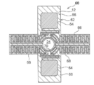
- the heating element 60 according to the second embodiment is characterized in that the basic configuration is the same as that of the first embodiment, and the electrode portion 64 is provided at the end of the heating element 68.
- the heating element 60 includes the sheet portion 12 as a plate-shaped base member made of an insulating flexible material and the heater portion 62 including the heating resistance element 68 as a heating member. , And an electrode portion 64.
- the heater portion 62 is integrally provided with a plurality of placement portions 66, and in the unfolded state is formed in a substantially cross shape like the heater portion 14 of the first embodiment in the thickness direction as shown in FIG. There is. Further, in the central portion 70 of the heater portion 62, a circular lens hole 24 is formed in the same manner as the heater portion 14 of the first embodiment.
- the heating resistive element 68 When power is supplied from the electrode section 64 to the heating resistive element 68 provided in the heater section 62, the heating resistive element 68 generates heat.
- the heating resistance element 68 is disposed in a substantially arc shape along the portion of the arrangement portion 66 of the heater portion 62 disposed in a meandering manner and the outer periphery of the lens hole 24 in the central portion 70 of the heater portion 62 Part of the That is, the heating resistive element 68 can heat the periphery of the arrangement portion 66 of the heater portion 62 and the lens hole 24.
- An electrode portion 64 is provided in each of the disposition portion 66 of the heater portion 62 and the disposition portion 66 opposed thereto. Two of the electrode portions 64 are provided as an example, one electrode portion 64 is a positive electrode, and the other electrode portion 64 is a negative electrode. In other words, the electrode portion 64 as the positive electrode and the electrode portion 64 as the negative electrode are separated by being arranged in different arrangement portions 66, respectively. Each of the electrode portions 64 is integrally formed at one end and the other end of the heating element 68 of the heater 62.
- power supply lines (not shown) are connected to the respective electrode portions 64 from the outside. Thus, power is supplied from the outside to the electrode portion 64 through the power supply line, and power is supplied from the electrode portion 64 to the heating resistor element 68.
- the plurality of arrangement units 66 are bent substantially at right angles to the central unit 20 in the same direction when attached to the camera 26 (FIG. 2) reference).
- the bent placement portions 66 are attached (attached) to the four rectangular side portions 33 that constitute the outer circumferential surface 32 of the camera 26.
- the heat generating body 60 has the heat conductive plate 40 as an abutting member between the camera 26 similarly to 1st Embodiment (refer FIG. 3).
- the heat generating body of the first embodiment is configured in the same manner as the first embodiment. An effect is obtained.
- the heating element 78 according to the third embodiment has a basic configuration similar to that of the first embodiment, and is characterized in that a PTC (Positive Temperature Coefficient) heater 76 is provided in the heater section 74.
- PTC Positive Temperature Coefficient
- the heating element 78 is a heater section 74 including the sheet member 12 as a plate-shaped base member made of an insulating flexible material and the PTC heater 76 as a heating member; And an electrode unit 80.
- the heater section 74 is integrally provided with a plurality of placement sections 82, and in the unfolded state is formed in a substantially cross shape like the heater section 14 of the first embodiment in the thickness direction as shown in FIG. There is. Further, in the central portion 90 of the heater portion 74, a circular lens hole 24 is formed as in the heater portion 14 of the first embodiment.
- the PTC heater 76 provided in the heater unit 74 includes a positive electrode pattern unit 84 (wiring unit), a negative electrode pattern unit 86 (wiring unit), and a heating element 88 (heating unit).
- the positive electrode pattern portion 84 is provided in each arrangement portion 82 of the heater portion 74, and a negative electrode pattern portion 86 is provided inside.
- the positive electrode pattern portion 84 and the negative electrode pattern portion 86 are formed to be separated from each other, and a heater element 88 is provided between the positive electrode pattern portion 84 and the negative electrode pattern portion 86.
- the positive electrode pattern portion 84 and the negative electrode pattern portion 86 have a portion formed in a substantially circular shape along the outer periphery of the lens hole 24 in the central portion 90 of the heater portion 74.
- the heating element 88 has a structure in which the electric resistance value changes according to the temperature. Specifically, when the temperature rises, the electric resistance value increases and it becomes difficult for the electricity to flow. Therefore, the temperature of the heating element 78 is maintained substantially constant. Thereby, the PTC heater 76 can heat the arrangement portions 82 of the heater portion 74 and the periphery of the lens hole 24 at a substantially constant temperature.
- an electrode portion 80 is provided in each of the placement portion 82 of the heater portion 74 and the placement portion 82 opposed thereto.
- Two of the electrode parts 80 are provided as an example, and one electrode part 80 is integrally formed with the positive electrode pattern part 84, and the other electrode part 80 is integrally formed with the negative electrode pattern part 86. It is formed.
- the electrode portion 80 as the positive electrode and the electrode portion 80 as the negative electrode are separated by being arranged in different arrangement portions 82.
- power supply lines (not shown) are connected to the respective electrode units 80 from the outside.
- power is supplied from the outside to the electrode unit 80 through the power supply line, and power is supplied from the electrode unit 80 to the positive electrode pattern unit 84 and the negative electrode pattern unit 86.
- the plurality of arrangement units 82 are bent substantially at right angles to the central unit 20 in the same direction when attached to the camera 26 (FIG. 2) reference).
- the bent placement portions 82 are attached (attached) to the four rectangular side portions 33 that constitute the outer circumferential surface 32 of the camera 26.
- the heat generating body 78 has the heat conductive plate 40 as an abutting member between the camera 26 similarly to 1st Embodiment (refer FIG. 3).
- the heating unit of the first embodiment is configured in the same manner as the heating unit of the first embodiment except that the PTC heater 76 is provided in the heater unit 74, the same effects as the first embodiment can be obtained. .
- the heater 74 is provided with a PTC heater 76.
- a PTC heater 76 When the PTC heater 76 is energized and the temperature of the PTC heater 76 rises, the electric resistance value becomes large and electricity does not flow easily. Therefore, the heater portion 74 is maintained at a substantially constant temperature, and the amount of power consumption is also kept constant, so that the power consumption can be reduced.
- the two electrode portions 16, 64, 80 are disposed at one of the placement portions 18, 66, 82 of the heater portion 14, 62, 74, and the other placement portion 18 opposite thereto. , 66, 82, respectively.
- the present invention is not limited to this, and the electrode portions 16, 64, 80 may be arranged in the adjacent arrangement portions 18, 66, 82, respectively.
- the camera 26 is formed in a substantially rectangular cylindrical shape by the four side surface portions 33, but is not limited to this, and is formed in a polygonal cylindrical shape constituted by three or five or more side surface portions 33 May be
- the heater portions 14, 62, 74 are configured to have the four placement portions 18, 66, 82, but the present invention is not limited to this.
- 62 and 74 may have three or less arrangement portions 18, 66 and 82 according to the shape of the camera 26, or may have five or more arrangement portions.
- the heat conductive plate 40 having the lens contact portion 48 is provided in the heater portions 14, 62, 74, the present invention is not limited to this, and the lens contact with the heater portions 14, 62, 74 themselves The portion 48 may be formed.
Landscapes
- Engineering & Computer Science (AREA)
- Physics & Mathematics (AREA)
- Aviation & Aerospace Engineering (AREA)
- General Physics & Mathematics (AREA)
- Electromagnetism (AREA)
- Multimedia (AREA)
- Signal Processing (AREA)
- Cameras Adapted For Combination With Other Photographic Or Optical Apparatuses (AREA)
- Studio Devices (AREA)
- Surface Heating Bodies (AREA)
- Resistance Heating (AREA)
Abstract
発熱体(10)は、複数の配置部(18)が一体的に形成されていると共に、通電することで発熱するヒータ部(14)と、ヒータ部(14)に複数設けられかつそれぞれが異なる配置部(18)に配置されている電極部(16)と、を有する。
Description
本発明は、発熱体に関する。
特開2007-115610号公報には、発熱体が開示されている。この発熱体は、通電することで発熱する略U字状のヒータ部を有している。ヒータ部の突出部には、外部からヒータ部に電力を供給する電力供給線が接続される2つの電極部が隣設されている。そして、この発熱体を、加熱したい対象物の外周面を覆うように設けることで、対象物を加熱する。
一方、このような発熱体において、ヒータ部の突出部を小型の対象物に設ける場合には、ヒータ部の突出部を小型化するのが望まれる。
本発明は上記問題を考慮し、配置部を小型化することができる発熱体を得ることを目的とする。
本開示の第1の態様に係る発熱体は、複数の配置部が一体的に設けられていると共に、通電することで発熱するヒータ部と、前記ヒータ部に複数設けられかつそれぞれが異なる前記配置部に配置されている電極部と、を有している。
本開示の第1の態様によれば、ヒータ部に設けられた複数の電極部は、それぞれが異なる配置部に配置されている。したがって、それぞれの配置部を小さくできる。
本開示の第2の態様に係る発熱体は、第1の態様において、前記配置部は、カメラの外周面に設けられている。
本開示の第2の態様によれば、配置部はカメラの外周面に設けられている。このため、カメラの外周面が小さくても、カメラの外周面に配置部を設けることができる。
本開示の第3の態様に係る発熱体は、第2の態様において、複数の前記配置部は、前記ヒータ部の中央部からそれぞれ異なる方向に延設されかつ前記カメラの外周面を構成する複数の側面部にそれぞれ設けられている。
本開示の第3の態様によれば、ヒータ部の複数の配置部は、ヒータ部の中央部からそれぞれ異なる方向に延設されていると共に、カメラの外周面を構成する側面部にそれぞれ設けられている。したがって、ヒータ部の配置部間に撓みが発生することを抑制でき、カメラの外周面にヒータ部を貼り付けやすくすることができる。
本開示の第4の態様に係る発熱体は、第2又は第3の態様において、前記ヒータ部には、前記カメラのレンズに対応したレンズ用孔が形成されている。
本開示の第4の態様によれば、ヒータ部には、カメラのレンズに対応したレンズ用孔が形成されていることで、カメラがレンズを介して良好に撮像できる。
本開示の第5の態様に係る発熱体は、第2~第4のいずれか一つの態様において、前記ヒータ部には、前記カメラのレンズに当接して前記レンズを加熱するレンズ当接部が設けられている。
本開示の第5の態様によれば、ヒータ部にレンズ当接部が設けられており、レンズ当接部が、カメラのレンズに当接して、レンズを加熱する。つまり、レンズに熱が伝わりやすくなるため、レンズに付着する氷や霜を良好に溶かすことができる。
本開示の第1の態様に係る発熱体は、配置部を小型化することができるという優れた効果を有する。
本開示の第2の態様に係る発熱体は、カメラの外周面が小さくてもカメラの外周面に配置部を設けることができるという優れた効果を有する。
本開示の第3の態様に係る発熱体は、カメラへのヒータ部の組み付け性を向上させることができるという優れた効果を有する。
本開示の第4の態様に係る発熱体は、カメラの撮像画像を良好にすることができるという優れた効果を有する。
本開示の第5の態様に係る発熱体は、カメラの視界を良好に確保することができるという優れた効果を有する。
(第1実施形態)
以下、図1~5を用いて、本発明に係る発熱体の第1実施形態について説明する。
以下、図1~5を用いて、本発明に係る発熱体の第1実施形態について説明する。
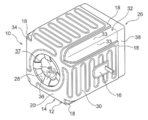
図1に示されるように、発熱体10(ヒータ)は、絶縁性を有する柔軟な材質で構成された板状とされた基部材としてのシート部材12と発熱部材としての発熱抵抗素子30とを含んで構成されたヒータ部14と、電極部16と、を含んで構成されている。ヒータ部14は、複数の配置部18が一体的に設けられかつ展開状態では板厚方向視で略十字状に形成されている。
配置部18は、複数(一例として4つ)設けられており、それぞれの配置部18は、ヒータ部14の中央部20を中心にヒータ部14の板厚方向と直交する方向でそれぞれ異なる方向に延設されている。具体的には、一方の配置部18と、この一方の配置部18に中央部20を挟んで対向する他方の配置部18とは、同一直線状に沿って配置されている。そして、一方の配置部18とこれと対向する他方の配置部18との組み合わせを1組とすると、本実施形態のヒータ部14ではこの配置部18の組み合わせが2組設けられていると共に、各組の配置部18の対向方向は中央部20を中心として略直角にて異なる方向にされている。
ヒータ部14の中央部20には、ヒータ部14の板厚方向で貫通された円形のレンズ用孔24が形成されている。このレンズ用孔24は、後述するカメラ26のレンズ28の周囲にある傾斜部36に対応した位置及び大きさに形成されている(図2参照)。
ヒータ部14には、発熱抵抗素子30が設けられている。この発熱抵抗素子30に電極部16から電力が供給されると発熱抵抗素子30が発熱する。発熱抵抗素子30は、ヒータ部14のそれぞれの配置部18において蛇行状に配置されている部分と共に、ヒータ部14の中央部20におけるレンズ用孔24の外周に沿って略円弧状に配置されている部分を有している。つまり、発熱抵抗素子30は、ヒータ部14のそれぞれの配置部18及びレンズ用孔24の周辺を熱することができる。
ヒータ部14の一つの配置部18と、これと対向する配置部18とには、それぞれ電極部16が設けられている。この電極部16は、一例として2つ設けられており、一方の電極部16は正極とされかつ他方の電極部16は負極とされている。換言すると、正極としての電極部16と負極としての電極部16とは、それぞれ異なる配置部18に配置されることで離間されている。そして、それぞれの電極部16は、ヒータ部14の発熱抵抗素子30に接続されており、それぞれの電極部16には外部から図示しない電力供給線が接続されている。これにより、外部から電力供給線を介して電極部16へと電力が供給され、電極部16から発熱抵抗素子30へと電力が供給される。なお、この電極部16には、図示しない封止材が塗布されている。
図2に示されるように、ヒータ部14のカメラ26への取り付け状態では、複数の配置部18が中央部20に対して略直角かつ同一方向へ折り曲げられている。そして、折り曲げられた配置部18は、カメラ26の外周面32を構成する4つの矩形状の側面部33にそれぞれ取り付けられている(貼り付けられている)。このカメラ26は、長手方向の一方の端部に底壁部34(図3も参照)が設けられていると共に、この底壁部34には、傾斜部36と貫通孔37とが形成されている。傾斜部36は、底壁部34の中央部に形成されて底壁部34の板厚方向に貫通された貫通孔37の周囲に設けられていると共に、底壁部34の面直角方向視で円環形に形成されている。そして、傾斜部36は、底壁部34の中央部に向かうに連れてカメラ26の内部側へと傾けられている。
底壁部34の貫通孔37の内部には、レンズ28が設けられている。このレンズ28は、カメラ26の内部に設けられた図示しないイメージセンサ基板に取り付けられており、カメラ26がレンズ28を介して撮像する構成とされている。また、カメラ26の底壁部34とは反対側の端部には、図示しないパッキンを介してカバー38が取り付けられており、これによってカメラ26の内部への水等の浸入が制限されている。
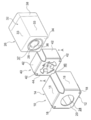
図3に示されるように、発熱体10は、カメラ26との間に当接部材としての導熱板40を有している。この導熱板40は、ヒータ部14に取り付けられている(貼り付けられている)と共に、一例としてアルミ合金で構成された板材により構成されている。そして、導熱板40は、複数(一例として4つ)の側板部42が一体的に形成されかつ図示はしないが展開状態において板厚方向視でヒータ部14と同様に略十字状に形成されている。
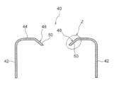
導熱板40の側板部42は、導熱板40の中央部44を中心にヒータ部14の配置部18に沿って配置部18の延設方向中間まで延設されている。つまり、図4に示されるように、側板部42は導熱板40の中央部44に対して略直角かつ同一方向へ折り曲げられている。
また、導熱板40の中央部44には、板厚方向に貫通されたレンズ用孔46が形成されている(図3参照)。このレンズ用孔46は、カメラ26のレンズ28に対応した位置に形成されていると共に、レンズ28より一回り大きいサイズ、具体的にはカメラ26の底壁部34における傾斜部36の外周部に沿ったサイズに設定されている。
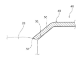
レンズ用孔46の周部には、レンズ当接部48が複数設けられている。このレンズ当接部48は、一例として4つ形成されていると共に、レンズ用孔46における4つの側板部42の幅方向略中央に対応した位置にそれぞれ設けられてカメラ26のレンズ28を介する撮像領域外に配置されている(図3参照)。レンズ当接部48は、基端部が中央部44の同一面上にてレンズ用孔46の中央に向かって延設されていると共に、先端部50がカメラ26のレンズ28の表面側へと屈曲されている。この先端部50は、図5に示されるように、カメラ26の傾斜部36に沿って延設されていると共に、先端部50における先端縁52は、レンズ28の表面と当接する構成とされている。
(第1実施形態の作用・効果)
次に、本実施形態の作用並びに効果を説明する。
次に、本実施形態の作用並びに効果を説明する。
本実施形態では、図1に示されるように、ヒータ部14に設けられた複数の電極部16は、それぞれがヒータ部14における異なる配置部18に配置されている。したがって、複数の電極部16を同一の配置部18に配置させる場合と比べて、各配置部18における電極部16を配置するスペースが小さくなる。これにより、それぞれの配置部18を小さくすることができる。
また、複数の電極部16はそれぞれ別の配置部18に分かれて配置されていることから、電極部16同士の間は離間している。したがって、異物が電極部16同士の間に挟まることでショートするのを抑制することができる。
さらに、図2に示されるように、配置部18はカメラ26の外周面32の側面部33に設けられている。このため、カメラ26の側面部33が小さくても、カメラ26の側面部33に配置部18を設けることができる。したがって、カメラ26の外周面32を介してカメラ26のレンズ28を加熱することができるので、レンズ28に付着する氷や霜を取り除くことができる。これにより、氷や霜が付く環境下にカメラ26があっても、カメラ26が視界を確保した状態で撮像することができる。
さらにまた、ヒータ部14の複数の配置部18は、ヒータ部14の中央部20からそれぞれ異なる方向に延設されていると共に、カメラ26の外周面32を構成する4つの側面部33にそれぞれ貼り付けられている。したがって、ヒータ部14の配置部18間に撓みが発生することを抑制でき、カメラ26の外周面32にヒータ部14を貼り付けやすくすることができる。これにより、発熱体10のカメラ26への組み付け性を向上させることができる。
また、レンズ28に当接しているレンズ当接部48を有する導熱板40がヒータ部14に設けられていることから、ヒータ部14からの熱が導熱板40のレンズ当接部48を介してカメラ26のレンズ28へと伝達する。つまり、レンズ28に熱が伝わりやすくなるため、レンズ28に付着する氷や霜を良好に溶かすことができる。これにより、カメラ26の視界を良好に確保することができる。
さらに、ヒータ部14には、カメラ26のレンズ28に対応したレンズ用孔24が形成されていると共に、導熱板40にレンズ用孔46が形成されていることで、カメラ26がヒータ部14及び導熱板40に遮られることなくレンズ28を介して良好に撮像できる。これにより、カメラ26の撮像画像を良好にすることができる。
(第2実施形態)
次に、図6を用いて、本発明の第2実施形態に係る発熱体について説明する。なお、前述した第1実施形態と基本的に同一の構成部分については、同一符号を付してその説明を省略する。
次に、図6を用いて、本発明の第2実施形態に係る発熱体について説明する。なお、前述した第1実施形態と基本的に同一の構成部分については、同一符号を付してその説明を省略する。
この第2実施形態に係る発熱体60は、基本的な構成は第1実施形態と同様とされ、電極部64が発熱抵抗素子68の端部に設けられている点に特徴がある。
すなわち、発熱体60は、絶縁性を有する柔軟な材質で構成された板状とされた基部材としてのシート部材12と発熱部材としての発熱抵抗素子68とを含んで構成されたヒータ部62と、電極部64と、を含んで構成されている。ヒータ部62は、複数の配置部66が一体的に設けられかつ展開状態では図6に示されるように板厚方向視で第1実施形態のヒータ部14と同様に略十字状に形成されている。また、ヒータ部62の中央部70には、第1実施形態のヒータ部14と同様に円形のレンズ用孔24が形成されている。
ヒータ部62に設けられている発熱抵抗素子68に電極部64から電力が供給されると、発熱抵抗素子68が発熱する。発熱抵抗素子68は、ヒータ部62のそれぞれの配置部66において蛇行状に配置されている部分と、ヒータ部62の中央部70におけるレンズ用孔24の外周に沿って略円弧状に配置されている部分とを有している。つまり、発熱抵抗素子68は、ヒータ部62のそれぞれの配置部66及びレンズ用孔24の周辺を熱することができる。
ヒータ部62の一つの配置部66と、これと対向する配置部66とには、それぞれ電極部64が設けられている。この電極部64は、一例として2つ設けられており、一方の電極部64は正極とされかつ他方の電極部64は負極とされている。換言すると、正極としての電極部64と負極としての電極部64とは、それぞれ異なる配置部66に配置されることで離間されている。そして、それぞれの電極部64は、ヒータ部62の発熱抵抗素子68の一方の端部と他方の端部とにそれぞれ一体的に形成されている。
また、それぞれの電極部64には、外部から図示しない電力供給線が接続されている。これにより、外部から電力供給線を介して電極部64へと電力が供給され、電極部64から発熱抵抗素子68へと電力が供給される。
ヒータ部62は、第1実施形態のヒータ部14と同様に、カメラ26への取り付け状態では、複数の配置部66が中央部20に対して略直角かつ同一方向へ折り曲げられている(図2参照)。そして、折り曲げられた配置部66は、カメラ26の外周面32を構成する4つの矩形状の側面部33にそれぞれ取り付けられている(貼り付けられている)。また、発熱体60は、第1実施形態と同様に、カメラ26との間に当接部材としての導熱板40を有している(図3参照)。
ここで、上記構成によっても、電極部64が発熱抵抗素子68の端部に設けられている点以外は第1実施形態の発熱体と同様に構成されているので、第1実施形態と同様の効果が得られる。
(第3実施形態)
次に、図7を用いて、本発明の第3実施形態に係る発熱体について説明する。なお、前述した第1実施形態と基本的に同一の構成部分については、同一符号を付してその説明を省略する。
次に、図7を用いて、本発明の第3実施形態に係る発熱体について説明する。なお、前述した第1実施形態と基本的に同一の構成部分については、同一符号を付してその説明を省略する。
この第3実施形態に係る発熱体78は、基本的な構成は第1実施形態と同様とされ、ヒータ部74にPTC(Positive Temperature Coefficient)ヒータ76が設けられている点に特徴がある。
すなわち、発熱体78は、絶縁性を有する柔軟な材質で構成された板状とされた基部材としてのシート部材12と発熱部材としてのPTCヒータ76とを含んで構成されたヒータ部74と、電極部80と、を含んで構成されている。ヒータ部74は、複数の配置部82が一体的に設けられかつ展開状態では図7に示されるように板厚方向視で第1実施形態のヒータ部14と同様に略十字状に形成されている。また、ヒータ部74の中央部90には、第1実施形態のヒータ部14と同様に円形のレンズ用孔24が形成されている。
ヒータ部74に設けられているPTCヒータ76は、正電極パターン部84(配線部)と負電極パターン部86(配線部)と発熱素子88(発熱部)とを含んで構成されている。正電極パターン部84は、ヒータ部74のそれぞれの配置部82に設けられていると共に、内側に負電極パターン部86が設けられている。正電極パターン部84と負電極パターン部86とは、互いに離間するように形成されていると共に、正電極パターン部84と負電極パターン部86との間には発熱素子88が設けられている。なお、正電極パターン部84及び負電極パターン部86には、ヒータ部74の中央部90におけるレンズ用孔24の外周に沿って略円状に形成された部分を有している。そして、後述する電極部80から電力が供給されると、正電極パターン部84と負電極パターン部86との間にある発熱素子88に電気が流れてこの発熱素子88が発熱する。この発熱素子88は、温度により電気抵抗値が変化する構成とされており、具体的には温度が上がると電気抵抗値が大きくなって電気が流れ難くなる。したがって、発熱体78は略一定に温度が保たれる。これにより、PTCヒータ76は、ヒータ部74のそれぞれの配置部82及びレンズ用孔24の周辺を略一定温度で熱することができる。
また、ヒータ部74の一つの配置部82と、これと対向する配置部82とには、それぞれ電極部80が設けられている。この電極部80は、一例として2つ設けられており、一方の電極部80は正電極パターン部84に一体的に形成されており、他方の電極部80は負電極パターン部86に一体的に形成されている。換言すると、正極としての電極部80と負極としての電極部80とは、それぞれ異なる配置部82に配置されることで離間されている。
また、それぞれの電極部80には、外部から図示しない電力供給線が接続されている。これにより、外部から電力供給線を介して電極部80へと電力が供給され、電極部80から正電極パターン部84及び負電極パターン部86へと電力が供給される。
ヒータ部74は、第1実施形態のヒータ部14と同様に、カメラ26への取り付け状態では、複数の配置部82が中央部20に対して略直角かつ同一方向へ折り曲げられている(図2参照)。そして、折り曲げられた配置部82は、カメラ26の外周面32を構成する4つの矩形状の側面部33にそれぞれ取り付けられている(貼り付けられている)。また、発熱体78は、第1実施形態と同様に、カメラ26との間に当接部材としての導熱板40を有している(図3参照)。
ここで、上記構成によっても、ヒータ部74にPTCヒータ76が設けられている点以外は第1実施形態の発熱体と同様に構成されているので、第1実施形態と同様の効果が得られる。
また、ヒータ部74にはPTCヒータ76が設けられており、PTCヒータ76に通電してPTCヒータ76の温度が上がると、電気抵抗値が大きくなって電気が流れ難くなる。したがって、ヒータ部74は略一定の温度に保たれると共に、消費電力量も一定に抑えられるため、消費電力を低減することが可能となる。
なお、上述した第1~第3実施形態では、2つの電極部16、64、80がヒータ部14、62、74における一方の配置部18、66、82とこれに対向する他方の配置部18、66、82とにそれぞれ配置された構成とされているが、これに限らず、隣設する配置部18、66、82にそれぞれ電極部16、64、80を配置した構成としてもよい。
また、カメラ26は、4つの側面部33により略矩形筒状に形成されているが、これに限らず、3つ又は5つ以上の側面部33により構成された多角形筒状に形成されていてもよい。これに合わせて、第1~第3実施形態では、ヒータ部14、62、74は4つの配置部18、66、82を有した構成とされているが、これに限らず、ヒータ部14、62、74はカメラ26の形状に合わせて配置部18、66、82を3つ以下有した構成としてもよいし5つ以上有した構成としてもよい。
さらに、ヒータ部14、62、74には、レンズ当接部48を有する導熱板40が設けられた構成とされているが、これに限らず、ヒータ部14、62、74自体にレンズ当接部48を形成した構成としてもよい。
以上、本発明の実施形態について説明したが、本発明は、上記に限定されるものでなく、その主旨を逸脱しない範囲内において上記以外にも種々変形して実施することが可能であることは勿論である。
2016年6月3日に出願された日本国特許出願2016-112063号の開示は、その全体が参照により本明細書に取り込まれる。
Claims (8)
- 複数の配置部が一体的に設けられていると共に、通電することで発熱するヒータ部と、
前記ヒータ部に複数設けられかつそれぞれが異なる前記配置部に配置されている電極部と、
を有する発熱体。 - 前記配置部は、カメラの外周面に設けられている、
請求項1記載の発熱体。 - 複数の前記配置部は、前記ヒータ部の中央部からそれぞれ異なる方向に延設されかつ前記カメラの外周面を構成する複数の側面部にそれぞれ設けられている、
請求項2記載の発熱体。 - 前記ヒータ部には、前記カメラのレンズに対応したレンズ用孔が形成されている、
請求項2又は請求項3記載の発熱体。 - 前記ヒータ部には、前記カメラのレンズに当接して前記レンズを加熱するレンズ当接部が設けられている、
請求項2~請求項4のいずれか一項に記載の発熱体。 - 前記ヒータ部は、発熱抵抗素子を含み、
前記電極部は、前記発熱抵抗素子の端部に設けられている、
請求項1~請求項5のいずれか一項に記載の発熱体。 - 前記ヒータ部は、PTCヒータを含む、
請求項1~請求項5のいずれか一項に記載の発熱体。 - 前記PTCヒータは、
正電極パターン部と、負電極パターン部と、発熱素子とを含む、
請求項7に記載の発熱体。
Priority Applications (1)
| Application Number | Priority Date | Filing Date | Title |
|---|---|---|---|
| US16/302,456 US20190278158A1 (en) | 2016-06-03 | 2017-05-25 | Heat generating body |
Applications Claiming Priority (2)
| Application Number | Priority Date | Filing Date | Title |
|---|---|---|---|
| JP2016-112063 | 2016-06-03 | ||
| JP2016112063A JP2017220308A (ja) | 2016-06-03 | 2016-06-03 | 発熱体 |
Publications (1)
| Publication Number | Publication Date |
|---|---|
| WO2017208981A1 true WO2017208981A1 (ja) | 2017-12-07 |
Family
ID=60477480
Family Applications (1)
| Application Number | Title | Priority Date | Filing Date |
|---|---|---|---|
| PCT/JP2017/019633 Ceased WO2017208981A1 (ja) | 2016-06-03 | 2017-05-25 | 発熱体 |
Country Status (3)
| Country | Link |
|---|---|
| US (1) | US20190278158A1 (ja) |
| JP (1) | JP2017220308A (ja) |
| WO (1) | WO2017208981A1 (ja) |
Cited By (3)
| Publication number | Priority date | Publication date | Assignee | Title |
|---|---|---|---|---|
| FR3082633A1 (fr) * | 2018-06-18 | 2019-12-20 | Delphi Technologies, Llc | Dispositif optique pour vehicule comprenant un element de chauffage |
| EP3584633A1 (fr) * | 2018-06-18 | 2019-12-25 | Aptiv Technologies Limited | Dispositif optique pour vehicule comprenant un element de chauffage |
| CN112119351A (zh) * | 2018-05-24 | 2020-12-22 | 麦克赛尔株式会社 | 透镜单元以及相机模块 |
Families Citing this family (10)
| Publication number | Priority date | Publication date | Assignee | Title |
|---|---|---|---|---|
| JP2019046786A (ja) * | 2017-09-04 | 2019-03-22 | 株式会社デンソー | ヒータ装置 |
| CN109991797B (zh) * | 2017-12-29 | 2021-04-06 | 光宝电子(广州)有限公司 | 加热装置及应用其的摄像器 |
| JP7293969B2 (ja) * | 2018-10-25 | 2023-06-20 | 株式会社デンソー | ヒータ装置 |
| WO2020085200A1 (ja) * | 2018-10-25 | 2020-04-30 | 株式会社デンソー | 光学装置 |
| KR102468587B1 (ko) * | 2018-11-30 | 2022-11-22 | 주식회사 미래오토스 | 발열 기능이 구비된 카메라 모듈 |
| IT201900001745A1 (it) * | 2019-02-06 | 2020-08-06 | Eltek Spa | Semilavorato di dispositivo riscaldatore elettrico, dispositivo riscaldatore elettrico, e metodi di realizzazione |
| WO2020230420A1 (ja) * | 2019-05-16 | 2020-11-19 | 株式会社村田製作所 | 光学装置、および光学装置を備える光学ユニット |
| JP7527872B2 (ja) * | 2020-07-13 | 2024-08-05 | 株式会社クラベ | ヒータユニット及びその応用品 |
| JP7706277B2 (ja) * | 2021-06-30 | 2025-07-11 | ニデックインスツルメンツ株式会社 | レンズユニット |
| EP4167558A1 (en) * | 2021-10-15 | 2023-04-19 | Ficosa Adas, S.L.U. | Camera module and assembling method |
Citations (4)
| Publication number | Priority date | Publication date | Assignee | Title |
|---|---|---|---|---|
| JPS59151234U (ja) * | 1983-03-30 | 1984-10-09 | キヨ−ラク株式会社 | カメラ用保温カバ− |
| JPH08138842A (ja) * | 1994-11-15 | 1996-05-31 | Nippon Seiki Co Ltd | シートヒータ |
| JP2008012384A (ja) * | 2006-07-03 | 2008-01-24 | Advanced Pdp Development Corp | 微細ラインの形成方法 |
| JP2010147024A (ja) * | 2008-12-19 | 2010-07-01 | Tesa Se | 加熱平面要素およびその取付方法 |
-
2016
- 2016-06-03 JP JP2016112063A patent/JP2017220308A/ja active Pending
-
2017
- 2017-05-25 WO PCT/JP2017/019633 patent/WO2017208981A1/ja not_active Ceased
- 2017-05-25 US US16/302,456 patent/US20190278158A1/en not_active Abandoned
Patent Citations (4)
| Publication number | Priority date | Publication date | Assignee | Title |
|---|---|---|---|---|
| JPS59151234U (ja) * | 1983-03-30 | 1984-10-09 | キヨ−ラク株式会社 | カメラ用保温カバ− |
| JPH08138842A (ja) * | 1994-11-15 | 1996-05-31 | Nippon Seiki Co Ltd | シートヒータ |
| JP2008012384A (ja) * | 2006-07-03 | 2008-01-24 | Advanced Pdp Development Corp | 微細ラインの形成方法 |
| JP2010147024A (ja) * | 2008-12-19 | 2010-07-01 | Tesa Se | 加熱平面要素およびその取付方法 |
Cited By (8)
| Publication number | Priority date | Publication date | Assignee | Title |
|---|---|---|---|---|
| CN112119351A (zh) * | 2018-05-24 | 2020-12-22 | 麦克赛尔株式会社 | 透镜单元以及相机模块 |
| FR3082633A1 (fr) * | 2018-06-18 | 2019-12-20 | Delphi Technologies, Llc | Dispositif optique pour vehicule comprenant un element de chauffage |
| EP3584633A1 (fr) * | 2018-06-18 | 2019-12-25 | Aptiv Technologies Limited | Dispositif optique pour vehicule comprenant un element de chauffage |
| EP3584620A1 (fr) * | 2018-06-18 | 2019-12-25 | Aptiv Technologies Limited | Dispositif optique pour vehicule comprenant un element de chauffage |
| CN110620855A (zh) * | 2018-06-18 | 2019-12-27 | Aptiv技术有限公司 | 包括加热元件的车辆用光学装置 |
| CN110618514A (zh) * | 2018-06-18 | 2019-12-27 | Aptiv技术有限公司 | 包括加热元件的车辆用光学装置 |
| US11385458B2 (en) | 2018-06-18 | 2022-07-12 | Aptiv Technologies Limited | Optical device for a vehicle comprising a heating element |
| US11653078B2 (en) | 2018-06-18 | 2023-05-16 | Aptiv Technologies Limited | Optical device with a flexible heating element |
Also Published As
| Publication number | Publication date |
|---|---|
| US20190278158A1 (en) | 2019-09-12 |
| JP2017220308A (ja) | 2017-12-14 |
Similar Documents
| Publication | Publication Date | Title |
|---|---|---|
| WO2017208981A1 (ja) | 発熱体 | |
| US11042076B2 (en) | Camera module with heating element | |
| JP7312164B2 (ja) | レンズユニットおよびカメラモジュール | |
| KR20240104081A (ko) | 카메라 모듈용 박막 히터 및 이를 갖는 카메라 모듈 | |
| JP6245101B2 (ja) | 輻射ヒータ装置 | |
| JP5537648B2 (ja) | センサ装置及び測定装置 | |
| JP2022189874A (ja) | 面状発熱体、および、車両用ウインドシールド装置 | |
| JP6568951B2 (ja) | 硬度可変アクチュエータ | |
| WO2018052043A1 (ja) | 撮像装置 | |
| WO2021024718A1 (ja) | 測温モジュール及び蓄電モジュール | |
| JP2019200349A5 (ja) | ||
| JP2023090254A5 (ja) | ||
| KR20140131138A (ko) | 감시 카메라 장치 | |
| JP5668898B2 (ja) | 圧電トランス装置 | |
| KR20170070739A (ko) | 열전소자 및 이를 포함하는 웨어러블 기기 | |
| JP5718954B2 (ja) | 圧電トランス | |
| WO2021090905A1 (ja) | シャント抵抗モジュール及び、シャント抵抗モジュールの実装構造 | |
| JP2014022493A5 (ja) | ||
| WO2013105356A1 (ja) | 静電霧化装置 | |
| JP6477394B2 (ja) | 電気ヒータ | |
| JP6294692B2 (ja) | 基板構造 | |
| JP4029025B2 (ja) | 面状ヒータ | |
| JP4681350B2 (ja) | 電気接続箱 | |
| JP2009129816A (ja) | 電熱線 | |
| KR101539921B1 (ko) | 저항발열히터 |
Legal Events
| Date | Code | Title | Description |
|---|---|---|---|
| NENP | Non-entry into the national phase |
Ref country code: DE |
|
| 121 | Ep: the epo has been informed by wipo that ep was designated in this application |
Ref document number: 17806537 Country of ref document: EP Kind code of ref document: A1 |
|
| 122 | Ep: pct application non-entry in european phase |
Ref document number: 17806537 Country of ref document: EP Kind code of ref document: A1 |