WO2017208819A1 - 局所音場形成装置および方法、並びにプログラム - Google Patents
局所音場形成装置および方法、並びにプログラム Download PDFInfo
- Publication number
- WO2017208819A1 WO2017208819A1 PCT/JP2017/018498 JP2017018498W WO2017208819A1 WO 2017208819 A1 WO2017208819 A1 WO 2017208819A1 JP 2017018498 W JP2017018498 W JP 2017018498W WO 2017208819 A1 WO2017208819 A1 WO 2017208819A1
- Authority
- WO
- WIPO (PCT)
- Prior art keywords
- speaker
- sound
- sound field
- speaker array
- local
- Prior art date
Links
Images


Classifications
-
- H—ELECTRICITY
- H04—ELECTRIC COMMUNICATION TECHNIQUE
- H04R—LOUDSPEAKERS, MICROPHONES, GRAMOPHONE PICK-UPS OR LIKE ACOUSTIC ELECTROMECHANICAL TRANSDUCERS; DEAF-AID SETS; PUBLIC ADDRESS SYSTEMS
- H04R1/00—Details of transducers, loudspeakers or microphones
- H04R1/20—Arrangements for obtaining desired frequency or directional characteristics
- H04R1/32—Arrangements for obtaining desired frequency or directional characteristics for obtaining desired directional characteristic only
- H04R1/40—Arrangements for obtaining desired frequency or directional characteristics for obtaining desired directional characteristic only by combining a number of identical transducers
- H04R1/403—Arrangements for obtaining desired frequency or directional characteristics for obtaining desired directional characteristic only by combining a number of identical transducers loud-speakers
-
- H—ELECTRICITY
- H04—ELECTRIC COMMUNICATION TECHNIQUE
- H04R—LOUDSPEAKERS, MICROPHONES, GRAMOPHONE PICK-UPS OR LIKE ACOUSTIC ELECTROMECHANICAL TRANSDUCERS; DEAF-AID SETS; PUBLIC ADDRESS SYSTEMS
- H04R3/00—Circuits for transducers, loudspeakers or microphones
-
- H—ELECTRICITY
- H04—ELECTRIC COMMUNICATION TECHNIQUE
- H04R—LOUDSPEAKERS, MICROPHONES, GRAMOPHONE PICK-UPS OR LIKE ACOUSTIC ELECTROMECHANICAL TRANSDUCERS; DEAF-AID SETS; PUBLIC ADDRESS SYSTEMS
- H04R3/00—Circuits for transducers, loudspeakers or microphones
- H04R3/005—Circuits for transducers, loudspeakers or microphones for combining the signals of two or more microphones
-
- H—ELECTRICITY
- H04—ELECTRIC COMMUNICATION TECHNIQUE
- H04R—LOUDSPEAKERS, MICROPHONES, GRAMOPHONE PICK-UPS OR LIKE ACOUSTIC ELECTROMECHANICAL TRANSDUCERS; DEAF-AID SETS; PUBLIC ADDRESS SYSTEMS
- H04R3/00—Circuits for transducers, loudspeakers or microphones
- H04R3/12—Circuits for transducers, loudspeakers or microphones for distributing signals to two or more loudspeakers
Definitions
- the present technology relates to a local sound field forming apparatus, method, and program, and more particularly, to a local sound field forming apparatus, method, and program that can reduce leakage of sound in an unintended direction.
- a local sound field forming method by superdirectivity control using a parametric speaker is known.
- the parametric speaker in the method based on superdirectivity control using a parametric speaker, once the parametric speaker is installed, it can be used only for a predetermined purpose, and some device for safety is required. Furthermore, since the frequency band that can be used as playback sound is limited, playback content is also limited.
- Patent Document 1 By using these methods described in Patent Document 1 and Non-Patent Document 1, it is possible not only to form a local sound field without restricting the playback content, but also to propagate waves in the lateral direction with respect to the speaker array. Can be suppressed to some extent.
- the present technology has been made in view of such a situation, and is capable of reducing leakage of sound in an unintended direction.
- a local sound field formation device convolves a local sound field formation filter coefficient recording unit that records an audio filter coefficient for forming a sound field by an evanescent wave, and the audio filter coefficient and the sound source signal. And a speaker array that includes a plurality of speakers including a directional speaker, and that reproduces sound based on the speaker drive signal.
- the directional speaker can be a plane speaker or a plane wave speaker.
- the speaker array can be a linear speaker array or a planar speaker array.
- More than half of the plurality of speakers constituting the speaker array can be the directional speakers.
- a local sound field forming method or program includes a local sound field forming filter coefficient recording unit that records an audio filter coefficient for forming a sound field by an evanescent wave, the audio filter coefficient, and a sound source signal.
- a local sound field of a local sound field forming apparatus comprising: a filter unit that generates a speaker drive signal by convolution, and a speaker array that includes a plurality of speakers including a directional speaker and reproduces sound based on the speaker drive signal It is a formation method or program, Comprising: The said filter part produces
- a local sound field forming filter coefficient recording unit that records an audio filter coefficient for forming a sound field by an evanescent wave, and a speaker driving signal is convoluted with the audio filter coefficient and the sound source signal.
- the speaker drive signal is generated by the filter unit. Generated and reproduced by the speaker array based on the speaker drive signal.
- This technology uses a loudspeaker array to form a local sound field that is a sound field in which sound pressure sufficient for listening is maintained only in the vicinity of the loudspeaker array and the sound pressure is sharply attenuated in the distance. is there.
- an evanescent wave is generated by using a speaker array to form a local sound field.
- the evanescent wave is a wave having a property that the sound pressure is exponentially attenuated in the direction perpendicular to the speaker array.
- the sound of the content can be reproduced so that a sufficient sound pressure is maintained only in a desired region, but the length of the speaker array is practically finite. Then, in practice, sound may leak in an unintended direction.
- the horizontal direction indicates the direction in which the speakers of the speaker array are arranged in space, and this direction is also referred to as the x direction below.
- the vertical direction indicates a direction perpendicular to the x direction in space, and hereinafter this direction is also referred to as the y direction.
- the y direction is a direction parallel to the direction in which sound is output by the speaker array.
- a portion indicated by an arrow A11 indicates a state of a wavefront of sound in a space at a certain time when a sound field is formed by an evanescent wave using a speaker array SPA11 composed of 40 speakers.
- the shading at each position indicates the amplitude of the sound wave.
- the portion indicated by arrow A12 indicates the sound pressure at each position in the space when the sound field indicated by arrow A11 is formed by the speaker array SPA11.
- the shading at each position indicates the sound pressure. .
- the portion indicated by arrow A13 in FIG. 1 shows the state of the sound wave front in space at a certain time when a sound field is formed by an evanescent wave using the speaker array SPA12 composed of 20 speakers. Show.
- the shading at each position indicates the amplitude of the sound wave.
- the portion indicated by arrow A14 indicates the sound pressure at each position in the space when the sound field indicated by arrow A13 is formed by the speaker array SPA12.
- the shading at each position indicates the sound pressure. .
- the sound pressure is large and the sound can be sufficiently heard.
- the sound pressure decreases as the distance from the area indicated by the arrow Q13 decreases.
- the area indicated by the arrow Q14, the area indicated by the arrow Q15, the area indicated by the arrow Q16, and the like are compared with those in the speaker array SPA11. And a lot of sound has leaked out.
- the horizontal direction indicates the direction in which the speakers of the speaker array SPA11 are arranged in space, that is, the x direction described above, and the vertical direction indicates the y direction described above.
- the portion indicated by arrow A21 shows the state of the wavefront of sound in space at a certain time when a sound field is formed by reproducing sound having a time frequency of 500 Hz using an evanescent wave using the speaker array SPA11. Is shown.
- the shading at each position indicates the amplitude of the sound wave.
- the portion indicated by the arrow A22 indicates the sound pressure at each position in the space when the sound field indicated by the arrow A21 is formed by the speaker array SPA11.
- the shading at each position indicates the sound pressure. .
- a portion indicated by an arrow A23 is a space on a certain time when a sound field is formed by reproducing sound having a time frequency of 1500 Hz by an evanescent wave using the speaker array SPA11. It shows the state of the sound wave front.
- the shading at each position indicates the amplitude of the sound wave.
- the portion indicated by the arrow A24 indicates the sound pressure at each position in the space when the sound field indicated by the arrow A23 is formed by the speaker array SPA11.
- the shading at each position indicates the sound pressure. .
- the sound pressure is large and the sound can be sufficiently heard.
- the sound pressure decreases as the distance from the area indicated by the arrow Q23 decreases.
- the sound is lower than when 500 Hz sound is reproduced. Many leaked.
- a speaker array including a directional speaker is used to reduce leakage of sound in an unintended direction. I was able to.
- the directional speaker is, for example, a speaker such as a flat speaker, a plane wave speaker, and a parametric speaker, and is a speaker having higher directivity than a normal omnidirectional speaker.
- the portion indicated by arrow A31 indicates the sound pressure at each position in the space when sound is reproduced using the omnidirectional speaker SPK11.
- the shading at each position indicates the sound pressure.
- the sound pressure in each direction becomes equal, and the wavefront of the sound spreads in all directions.
- a portion indicated by an arrow A32 is a state of a wavefront of sound at a certain time when a sound field is formed by an evanescent wave using a speaker array SPA21 obtained by arranging a plurality of speakers similar to the omnidirectional speaker SPK11. Is shown. Here, the shading at each position indicates the amplitude of the sound wave.
- the portion indicated by the arrow A33 indicates the sound pressure at each position in the space when the sound field indicated by the arrow A32 is formed by the speaker array SPA21.
- the shading at each position indicates the sound pressure. .
- the sound pressure is high in the area indicated by the arrow Q31 in the vicinity of the speaker array SPA21 so that the sound can be sufficiently heard.
- the sound pressure is suddenly lowered, and the sound is hardly heard and a local sound field is formed.
- the portion indicated by arrow A41 indicates the sound pressure at each position in the space when sound is reproduced using the directional speaker SPK21.
- the shading at each position indicates the sound pressure.
- a portion indicated by an arrow A42 shows a state of a wavefront of sound in a space at a certain time when a sound field is formed by an evanescent wave using a speaker array SPA31 obtained by arranging a plurality of speakers similar to the directional speaker SPK21. Show.
- the shading at each position indicates the amplitude of the sound wave.
- the portion indicated by the arrow A43 indicates the sound pressure at each position in the space when the sound field indicated by the arrow A42 is formed by the speaker array SPA31.
- the shading at each position indicates the sound pressure. .
- the sound pressure is large in the area indicated by the arrow Q41 in the vicinity of the speaker array SPA31, and the sound can be heard sufficiently.
- the sound pressure suddenly decreases, and the sound is hardly heard and a local sound field is formed.
- the speaker array SPA31 composed of such directional speakers, a local sound field in which sound leakage is sufficiently suppressed can be formed even when the number of speakers described above is small or when high-frequency sound is reproduced. be able to.
- the number of speakers can be reduced by sufficiently reducing sound leakage, or the time frequency band that can be reproduced with sufficiently small sound leakage is increased to a higher frequency range. And can be expanded.
- the speaker array SPA21 shown in FIG. 3 is compared with the speaker array SPA31 shown in FIG. 4, when the number of speakers is 20 and the time frequency of the sound to be reproduced is 500 Hz, the sound leaks out. Is as shown in FIG.
- FIG. 5 parts corresponding to those in FIG. 3 or 4 are denoted by the same reference numerals, and the description thereof is omitted.
- the horizontal direction indicates the direction in which the speakers of the speaker array SPA21 or the speaker array SPA31 are arranged in space, that is, the above-described x direction, and in the drawing, the vertical direction indicates the above-described y direction.
- the portion indicated by arrow A51 indicates the state of the wavefront of the sound in space at a certain time when a sound field is formed by reproducing sound having a time frequency of 500 Hz by an evanescent wave using the speaker array SPA21.
- the speaker array SPA21 is composed of 20 omnidirectional speakers, and the shading at each position indicates the amplitude of the sound wave.
- the portion indicated by the arrow A52 indicates the sound pressure at each position in the space when the sound field indicated by the arrow A51 is formed by the speaker array SPA21.
- the shading at each position indicates the sound pressure. .
- the region in the vicinity of the speaker array SPA21 is a region where the sound is desired to be reproduced in the local sound field.
- the region indicated by the arrow Q51 to the arrow Q53 is not only near the region where the sound is desired to be reproduced, but is relatively far away. Sound has leaked to the position area.
- the portion indicated by arrow A53 shows the wavefront of the sound in space at a certain time when a sound field is formed by reproducing sound having a time frequency of 500 Hz by an evanescent wave using the speaker array SPA31. It shows a state.
- the speaker array SPA31 is composed of 20 directional speakers, and the shading at each position indicates the amplitude of the sound wave.
- the portion indicated by the arrow A54 indicates the sound pressure at each position on the space when the sound field indicated by the arrow A53 is formed by the speaker array SPA31.
- the shading at each position indicates the sound pressure. .
- the area near the speaker array SPA31 is the area where the sound is desired to be reproduced in the local sound field, but the sound leaks out near the area where the sound is desired to be reproduced, such as the area indicated by the arrows Q54 and Q55. ing.
- the speaker array SPA31 when used, sound leakage is greatly reduced as compared with the case where the speaker array SPA21 is used. That is, it can be seen that even when the speaker array is composed of a relatively small number of speakers, leakage of sound in an unintended direction can be sufficiently suppressed.
- FIG. 6 parts corresponding to those in FIG. 5 are denoted by the same reference numerals, and description thereof is omitted.
- the horizontal direction indicates the direction in which the speakers of the speaker array SPA21 or the speaker array SPA31 are arranged in space, that is, the above-described x direction, and in the drawing, the vertical direction indicates the above-described y direction.
- the portion indicated by arrow A61 indicates the state of the wavefront of the sound in space at a certain time when the sound field is formed by reproducing the sound having the time frequency of 1500 Hz by the evanescent wave using the speaker array SPA21.
- the speaker array SPA21 is composed of 40 omnidirectional speakers, and the shading at each position indicates the amplitude of the sound wave.
- the portion indicated by the arrow A62 indicates the sound pressure at each position in the space when the sound field indicated by the arrow A61 is formed by the speaker array SPA21.
- the shading at each position indicates the sound pressure. .
- the region in the vicinity of the speaker array SPA21 is a region where the sound is desired to be reproduced in the local sound field.
- the region indicated by the arrow Q61 and the arrow Q62 is not only near the region where the sound is desired to be reproduced, but is relatively far away. Sound leaks in a wide area up to the position area.
- the portion indicated by arrow A63 shows the wavefront of the sound on the space at a certain time when the sound field is formed by reproducing the sound having the time frequency of 1500 Hz by the evanescent wave using the speaker array SPA31. It shows a state.
- the speaker array SPA31 is composed of 40 directional speakers, and the shading at each position indicates the amplitude of the sound wave.
- the portion indicated by the arrow A64 indicates the sound pressure at each position in the space when the sound field indicated by the arrow A63 is formed by the speaker array SPA31.
- the shading at each position indicates the sound pressure. .
- the area in the vicinity of the speaker array SPA31 is the area where the sound is desired to be reproduced in the local sound field, but the sound leaks out in the vicinity of the area where the sound is desired to be reproduced, such as the area indicated by the arrows Q63 and Q64. ing.
- the speaker array SPA31 when used, sound leakage is greatly reduced as compared with the case where the speaker array SPA21 is used. That is, it can be seen that even when high frequency sound is reproduced, leakage of sound in an unintended direction can be sufficiently suppressed.
- the local sound field is not formed by combining the speaker array including the directional speaker and the signal processing at the time of generating the speaker driving signal for generating the evanescent wave. Sound leakage in the direction can be reduced. In particular, according to the present technology, sound leakage can be sufficiently suppressed even when the number of speakers in the speaker array is small or when high-frequency sound is reproduced.
- a speaker array when a speaker array is configured by combining a directional speaker and an omnidirectional speaker, the right half of the speaker array is configured by a plurality of omnidirectional speakers, and the remaining left half is configured by a plurality of directional speakers. You may make it do. Further, for example, a speaker array may be configured by alternately arranging directional speakers and omnidirectional speakers.
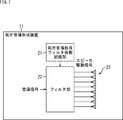
- FIG. 7 is a diagram illustrating a configuration example of a local sound field forming device to which the present technology is applied.
- the local sound field forming device 11 shown in FIG. 7 has a local sound field forming filter coefficient recording unit 21, a filter unit 22, and a speaker array 23.
- the local sound field forming filter coefficient recording unit 21 includes, for example, a non-volatile memory, and records in advance the coefficients of an audio filter for forming a local sound field by generating an evanescent wave to form a sound field. Yes. That is, the audio filter coefficient recorded in the local sound field forming filter coefficient recording unit 21 is a filter coefficient for the local sound field forming filter for forming a desired sound field by the evanescent wave.
- the local sound field forming filter coefficient recording unit 21 supplies the recorded audio filter coefficient to the filter unit 22.
- the filter unit 22 is supplied with a sound source signal that is a sound signal of a sound that forms a local sound field by the speaker array 23.
- the filter unit 22 performs a filtering process using the audio filter coefficient supplied from the local sound field forming filter coefficient recording unit 21 on the supplied sound source signal, so that the speaker array 23 forms a local sound field. For generating a speaker driving signal.
- the filter unit 22 supplies the speaker drive signal of each speaker thus obtained to the speaker array 23 to reproduce the sound.
- the speaker array 23 includes a linear speaker array obtained by arranging a plurality of speakers in a straight line, a planar speaker array obtained by arranging a plurality of speakers on a plane, and the like, and is based on a speaker drive signal supplied from the filter unit 22. , Play audio.
- an evanescent wave is generated by the speaker array 23, and a local sound field is formed in which sound can be heard only in the area near the speaker array 23.
- the speaker array 23 includes a plurality of speakers. As described above, at least one of the plurality of speakers is a directional speaker such as a planar speaker, a plane wave speaker, and a parametric speaker. It is said that. That is, some or all of the speakers constituting the speaker array 23 are directional speakers.
- more than half of the speakers constituting the speaker array 23 can be directional speakers such as a plane speaker and a plane wave speaker.
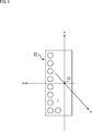
- the speaker array 23 is a planar speaker array, and a predetermined position on the planar speaker array is an origin O of the xyz coordinate system which is a three-dimensional orthogonal coordinate system.
- the horizontal direction in the figure is the x-axis direction (x direction)
- the front direction in the figure is the y-axis direction (y direction)
- the vertical direction in the figure is the z-axis direction (z Direction).
- the y direction is a direction perpendicular to the direction in which the speakers constituting the speaker array 23 are arranged, and when the local sound field is formed, the speaker array 23 generates an evanescent wave that attenuates in the y direction. Audio is played back.
- the filter coefficient of the audio filter for generating the evanescent wave attenuated in the y direction by the speaker array 23 is recorded.
- the filter coefficient constituting the audio filter is obtained as follows.
- the sound field p (V, t) at time t at an arbitrary position V satisfies the wave equation shown in the following equation (1).
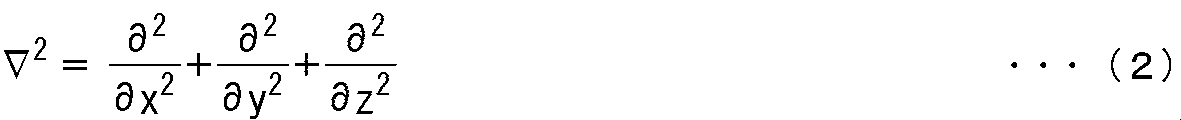
- Equation (1) c represents the speed of sound, and ⁇ 2 is as shown in Equation (2) below.
- i represents an imaginary unit
- ⁇ represents an angular frequency
- variable separation is performed as shown in the following equation (5) to separate the space differentiation and the time differentiation, and further using equation (4), the following equation:
- the Helmholtz equation shown in (6) is obtained.
- P (V, ⁇ ) indicates the sound field of the angular frequency ⁇ at the position V.
- the angular frequency is ⁇ pw and the wave numbers in the x direction, the y direction, and the z direction are k pw, x , k pw, y , and k pw, z
- the angular frequency ⁇ pw and the wave number The general solution of the Helmholtz equation shown in equation (6), which represents a plane wave propagating in the direction represented by k pw, x , wave number k pw, y , and wave number k pw, z , is shown in the following equation (7) It becomes.
- ⁇ ( ⁇ pw ) represents a delta function
- the wave of the wave number k pw, y shown in the upper part of Equation (9), that is, the upper side represents a normal propagation wave
- the wave of wave number k pw, y shown in the lower part of Equation (9), that is, the lower side Represents an evanescent wave.
- the wave number k pw, x and the wave number are satisfied so as to satisfy the following expression (11) using the constant ⁇ representing the magnitude of attenuation.
- k pw, z may be set.
- H 0 (2) represents the second kind Hankel function
- K 0 represents the Bessel function
- the spatial frequency spectrum D ′ (k x , ⁇ ) of the speaker drive signal is represented by the following equation (14) by the SDM (Spectral Division Method) method.
- SDM Spectrum Division Method
- the SDM method for example, “Jens Ahrens and Sascha Spors,“ Sound Field Reproduction Using Planar and Linear Arrays of Loudspeakers, ”in IEEE TRANSACTIONS ON AUDIO, SPEECH, AND LANGUAGE PROCESSING, VOL. 18, NO. 8, NOVEMBER 2010 . "Etc. are described in detail.
- y ref indicates the reference position serving as a reference in the y direction, that is, the position of the control point.
- the time-frequency spectrum D (x, ⁇ ) of the speaker drive signal shown in the following equation (15) is obtained by performing inverse spatial Fourier transform on the wave number k x from the equation (14) thus obtained.
- the audio filter of the speaker of index l is calculated from the equation (16) as shown in the following equation (17).
- the filter coefficient h (l, m) is obtained.
- m represents a time index.
- This filter coefficient h (l, m) is obtained by replacing x in the speaker drive signal d (x, t) shown in Expression (16) with an index l and replacing t with a time index m.
- the wavefront formed based on the sound source signal is subjected to windowing in the spatial direction. That is, the generation of propagation waves can be reduced.
- the filter coefficient for generating the evanescent wave may be obtained by other methods. .
- the filter unit 22 performs the calculation shown in the following equation (18), thereby convolving the filter coefficient h (l, m) of the audio filter supplied from the local sound field forming filter coefficient recording unit 21 with the sound source signal, and the speaker.
- the speaker drive signal s (l, n) of each speaker of the array 23 is calculated. That is, the speaker drive signal s (l, n) is generated by performing filter processing using an audio filter including the filter coefficient h (l, m) on the sound source signal.
- n indicates a time index and x (n) indicates a sound source signal.
- N indicates the filter length.
- the filter unit 22 supplies the speaker drive signal s (l, n) thus obtained to each speaker constituting the speaker array 23, and reproduces sound.
- step S11 the filter unit 22 reads the filter coefficient h (l, m) of each speaker from the local sound field forming filter coefficient recording unit 21, and for each speaker, the read filter coefficient h (l, m), The supplied sound source signal is convoluted to generate a speaker drive signal s (l, n).
- step S11 the calculation of the above equation (18) is performed for each speaker constituting the speaker array 23, and the speaker drive signal s (l, n) is generated.
- step S12 the filter unit 22 supplies the generated speaker drive signal s (l, n) to the speakers constituting the speaker array 23 to reproduce the sound, and the local sound field forming process ends. Thereby, the sound field formation by the evanescent wave is performed by the speaker array 23, and the local sound field is formed.
- the local sound field forming device 11 generates the speaker drive signal using the filter coefficient for performing the windowing in the spatial direction, and the sound based on the speaker drive signal by the speaker array 23 including the directional speaker as a component. Play. By doing so, it is possible to reduce leakage of sound in an unintended direction.
- FIG. 10 shows an example of a spatial spectrum of a speaker driving signal for generating an evanescent wave.
- the part indicated by arrow A71 indicates the spatial spectrum of the speaker drive signal, that is, the spatio-temporal spectrogram.
- the horizontal axis indicates the spatial frequency, that is, the wave number k x in the x direction
- the vertical axis indicates the time.
- the frequency f is shown.
- the shading in the spatial spectrum indicates the sound pressure (amplitude).
- the wave number k z in the z direction is set to 0, and the speakers constituting the speaker array 23 are arranged in a straight line on the x-axis.
- the boundary BD11-1 and the boundary BD11-2 represented by straight lines represent the boundary position between the evanescent region and the propagation wave region, that is, the evanescent boundary.
- the local sound field forming device 11 when sound is reproduced based on the speaker drive signal s (l, n), a spatial spectrum wavefront as shown by an arrow A71 is generated.
- the generated wave includes an evanescent wave. And a propagating wave.
- the area on the right side of the figure from the boundary BD11-1 and the left side of the figure from the boundary BD11-2 is the propagation wave area, and the wave in this propagation wave area becomes the propagation wave.
- the region on the left side of the boundary BD11-1 outside the evanescent boundary and the region on the right side of the boundary BD11-2 in the drawing are the evanescent region, and the waves in the evanescent region Is the evanescent wave.
- boundary BD11-1 and the boundary BD11-2 are simply referred to as the boundary BD11 when it is not necessary to distinguish them.
- the portion indicated by an arrow A72 indicates a predetermined region in the spatial spectrum shown in an arrow A71, i.e. the wave number k x parts in the linear L11, a relationship between the amplitude of the wave to be formed (sound waves). That is, the vertical axis in a portion indicated by an arrow A72 indicates the amplitude, and the horizontal axis represents the wave number k x.
- the portion indicated by the arrow W11 is observed as a spectrum peak. That is, a spectrum peak exists along the boundary BD11-2, and this spectrum peak is located in the evanescent region.
- the portion shown by the arrow W11 that is, the spectrum peak portion becomes the main lobe, and when sound is reproduced based on the speaker drive signal s (l, n), the evanescent wave is mainly used. Is generated.
- the influence of the side lobe increases as the number of speakers constituting the speaker array 23 decreases, and when ⁇ shown in Equation (11) is a constant, the influence of the side lobe increases as the time frequency becomes higher. Becomes larger.
- one or more speakers among the speakers constituting the speaker array 23 are directional speakers.
- a portion indicated by an arrow A ⁇ b> 81 indicates a spatial spectrum of a formed sound field, that is, a spatio-temporal spectrogram when all speakers constituting the speaker array 23 are omnidirectional speakers.
- a portion indicated by an arrow A82 indicates a spatial spectrum of a formed sound field, that is, a spatio-temporal spectrogram when all speakers constituting the speaker array 23 are directional speakers.
- the horizontal axis indicates the spatial frequency, that is, the wave number k x
- the vertical axis indicates the time frequency f.
- the shading in the spatial spectrum indicates the sound pressure (energy).
- the energy of the propagation wave region in the vicinity of the boundary BD11 is large, and a plane wave (propagation wave) propagating in the x direction, that is, the direction in which the speakers are arranged in the speaker array 23 is generated. That is, sound leakage in the x direction increases with respect to the speaker array 23.
- a portion indicated by an arrow A91 indicates a spatio-temporal spectrogram of a transfer characteristic of the speaker array 23, that is, a spatial spectrum, when all the speakers constituting the speaker array 23 are omnidirectional speakers.
- a portion indicated by an arrow A92 indicates a spatio-temporal spectrogram of a transfer characteristic of the speaker array 23, that is, a spatial spectrum, when all the speakers constituting the speaker array 23 are directional speakers.
- the horizontal axis indicates the spatial frequency, that is, the wave number k x
- the vertical axis indicates the time frequency f.
- the shading in the spatial spectrum indicates the sound pressure (energy).
- the propagation wave region near the evanescent boundary which is the boundary BD11, that is, the signal propagating in the x direction has a certain energy.
- the energy of the signal is smaller in the same region in the propagation wave region near the evanescent boundary that is the boundary BD11 than in the spatial spectrum indicated by the arrow A91. I understand.
- the above-described series of processing can be executed by hardware or can be executed by software.
- a program constituting the software is installed in the computer.
- the computer includes, for example, a general-purpose computer capable of executing various functions by installing a computer incorporated in dedicated hardware and various programs.
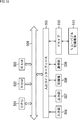
- FIG. 13 is a block diagram showing an example of the hardware configuration of a computer that executes the above-described series of processing by a program.
- a CPU Central Processing Unit
- ROM Read Only Memory
- RAM Random Access Memory
- An input / output interface 505 is further connected to the bus 504.
- An input unit 506, an output unit 507, a recording unit 508, a communication unit 509, and a drive 510 are connected to the input / output interface 505.
- the input unit 506 includes a keyboard, a mouse, a microphone, an image sensor, and the like.
- the output unit 507 includes a display, a speaker array, and the like.
- the recording unit 508 includes a hard disk, a nonvolatile memory, and the like.
- the communication unit 509 includes a network interface or the like.
- the drive 510 drives a removable recording medium 511 such as a magnetic disk, an optical disk, a magneto-optical disk, or a semiconductor memory.
- the CPU 501 loads the program recorded in the recording unit 508 to the RAM 503 via the input / output interface 505 and the bus 504 and executes the program, for example. Is performed.
- the program executed by the computer (CPU 501) can be provided by being recorded in a removable recording medium 511 as a package medium or the like, for example.
- the program can be provided via a wired or wireless transmission medium such as a local area network, the Internet, or digital satellite broadcasting.
- the program can be installed in the recording unit 508 via the input / output interface 505 by attaching the removable recording medium 511 to the drive 510. Further, the program can be received by the communication unit 509 via a wired or wireless transmission medium and installed in the recording unit 508. In addition, the program can be installed in advance in the ROM 502 or the recording unit 508.
- the program executed by the computer may be a program that is processed in time series in the order described in this specification, or in parallel or at a necessary timing such as when a call is made. It may be a program for processing.
- the present technology can take a cloud computing configuration in which one function is shared by a plurality of devices via a network and is jointly processed.
- each step described in the above flowchart can be executed by one device or can be shared by a plurality of devices.
- the plurality of processes included in the one step can be executed by being shared by a plurality of apparatuses in addition to being executed by one apparatus.
- the present technology can be configured as follows.
- a local sound field forming filter coefficient recording unit for recording an audio filter coefficient for forming a sound field by an evanescent wave;
- a filter unit that generates a speaker drive signal by convolving the audio filter coefficient and the sound source signal;
- a local sound field forming device comprising: a speaker array that includes a plurality of speakers including a directional speaker and reproduces sound based on the speaker drive signal.
- a local sound field forming filter coefficient recording unit for recording an audio filter coefficient for forming a sound field by an evanescent wave;
- a filter unit that generates a speaker drive signal by convolving the audio filter coefficient and the sound source signal;
- a local sound field forming method of a local sound field forming apparatus comprising: a speaker array including a plurality of speakers including a directional speaker and reproducing sound based on the speaker drive signal, The filter unit generates the speaker driving signal;
- a local sound field forming method including a step of reproducing sound based on the speaker drive signal by the speaker array.
- a local sound field forming filter coefficient recording unit for recording an audio filter coefficient for forming a sound field by an evanescent wave;
- a filter unit that generates a speaker drive signal by convolving the audio filter coefficient and the sound source signal;
- a computer that controls a local sound field forming device that includes a plurality of speakers including a directional speaker and includes a speaker array that reproduces sound based on the speaker drive signal.
- the filter unit generates the speaker driving signal,
- a program for executing processing including a step of reproducing sound based on the speaker drive signal by the speaker array.
Abstract
本技術は、意図しない方向への音の漏れ出しを低減させることができるようにする局所音場形成装置および方法、並びにプログラムに関する。 局所音場形成装置は、エバネッセント波により音場を形成するためのオーディオフィルタ係数を記録する局所音場形成フィルタ係数記録部と、オーディオフィルタ係数と音源信号とを畳み込んでスピーカ駆動信号を生成するフィルタ部と、指向性スピーカを含む複数のスピーカから構成され、スピーカ駆動信号に基づいて音を再生するスピーカアレイとを有する。本技術は局所音場形成装置に適用することができる。
Description
本技術は局所音場形成装置および方法、並びにプログラムに関し、特に、意図しない方向への音の漏れ出しを低減させることができるようにした局所音場形成装置および方法、並びにプログラムに関する。
近年、空港や駅などの公共の場においては、映像ディスプレイを用いて運航情報やサイネージが提示されている。
このように公共の場でコンテンツを提示するときに、映像に加えて音声を用いることで、より効果的にコンテンツの提示が可能になるが、一方で、その情報を必要としていない不特定多数の人にまで音声が届いてしまうことになる。
そこで、所望の領域近傍でのみ再生音を聞き取ることができ、その領域から外れると再生音を殆ど聞き取ることができないようにする局所音場形成技術が提案されている。
例えば、そのような局所音場を形成する方法として、パラメトリックスピーカを用いた超指向性制御による局所音場形成方法が知られている。
しかしながら、パラメトリックスピーカを用いた超指向性制御による方法では、一度、パラメトリックスピーカを設置すると決まった用途にしか使用することができず、安全性についても何らかの工夫が必要であった。さらに、再生音として使用できる周波数帯域が限られているため、再生コンテンツも制限されてしまう。
これに対して、再生コンテンツを制限することなく局所音場形成を実現する方法も提案されている。
例えば、そのような方法として、スピーカアレイを用いてエバネッセント波を生成する方法が提案されている(例えば、特許文献1参照)。また、エバネッセント波を生成するにあたり、有限長のスピーカアレイを用いることによる空間の打ち切り誤差を抑えるために、空間方向に窓掛けを行うことで誤差を減少させる方法も提案されている(例えば、非特許文献1参照)。
これらの特許文献1や非特許文献1に記載されている方法を用いれば、再生コンテンツを制限することなく局所音場を形成することができるだけでなく、スピーカアレイに対して横方向への伝搬波の漏れ出しをある程度抑えることができる。
Itou et al. "EVANESCENT WAVE REPRODUCTION USING LINEAR ARRAY OF LOUDSPEAKERS," in IEEE Workshop on Applications of Signal Processing to Audio and Acoustics (WASPAA), 2011.
しかしながら、上述した技術では、意図しない方向への音の漏れ出しを十分に抑えることができないことがあった。
例えば特許文献1や非特許文献1に記載の技術でコンテンツ再生を行う場合、スピーカアレイを構成するスピーカの数が少ないときや、時間周波数における高域の音声を再生するときには、意図しない方向への音の漏れ出しが多くなってしまう。
そうすると、所望の領域外でも再生コンテンツの音声を聞き取ることができる領域が生じてしまい、目的とする人以外にも音声が届いてしまう。
本技術は、このような状況に鑑みてなされたものであり、意図しない方向への音の漏れ出しを低減させることができるようにするものである。
本技術の一側面の局所音場形成装置は、エバネッセント波により音場を形成するためのオーディオフィルタ係数を記録する局所音場形成フィルタ係数記録部と、前記オーディオフィルタ係数と音源信号とを畳み込んでスピーカ駆動信号を生成するフィルタ部と、指向性スピーカを含む複数のスピーカから構成され、前記スピーカ駆動信号に基づいて音を再生するスピーカアレイとを備える。
前記指向性スピーカを、平面スピーカ、または平面波スピーカとすることができる。
前記スピーカアレイを、直線スピーカアレイ、または平面スピーカアレイとすることができる。
前記スピーカアレイを構成する前記複数の前記スピーカのうちの半分以上の前記スピーカを前記指向性スピーカとすることができる。
本技術の一側面の局所音場形成方法またはプログラムは、エバネッセント波により音場を形成するためのオーディオフィルタ係数を記録する局所音場形成フィルタ係数記録部と、前記オーディオフィルタ係数と音源信号とを畳み込んでスピーカ駆動信号を生成するフィルタ部と、指向性スピーカを含む複数のスピーカから構成され、前記スピーカ駆動信号に基づいて音を再生するスピーカアレイとを備える局所音場形成装置の局所音場形成方法またはプログラムであって、前記フィルタ部が前記スピーカ駆動信号を生成し、前記スピーカアレイが前記スピーカ駆動信号に基づいて音を再生するステップを含む。
本技術の一側面においては、エバネッセント波により音場を形成するためのオーディオフィルタ係数を記録する局所音場形成フィルタ係数記録部と、前記オーディオフィルタ係数と音源信号とを畳み込んでスピーカ駆動信号を生成するフィルタ部と、指向性スピーカを含む複数のスピーカから構成され、前記スピーカ駆動信号に基づいて音を再生するスピーカアレイとを備える局所音場形成装置において、前記フィルタ部により前記スピーカ駆動信号が生成され、前記スピーカアレイにより前記スピーカ駆動信号に基づいて音が再生される。
本技術の一側面によれば、意図しない方向への音の漏れ出しを低減させることができる。
なお、ここに記載された効果は必ずしも限定されるものではなく、本開示中に記載された何れかの効果であってもよい。
以下、図面を参照して、本技術を適用した実施の形態について説明する。
〈第1の実施の形態〉
〈本技術について〉
本技術は、スピーカアレイを用いて、そのスピーカアレイの近傍においてのみ聴取に十分な音圧が保たれ、遠方では急峻に音圧が減衰するような音場である局所音場を形成するものである。
〈本技術について〉
本技術は、スピーカアレイを用いて、そのスピーカアレイの近傍においてのみ聴取に十分な音圧が保たれ、遠方では急峻に音圧が減衰するような音場である局所音場を形成するものである。
本技術では、局所音場を形成するためにスピーカアレイが用いられてエバネッセント波が生成される。エバネッセント波とは、スピーカアレイに対して垂直方向に指数関数的に音圧が距離減衰する性質をもった波である。
このようなエバネッセント波を用いれば、所望の領域でのみ十分な音圧が保たれるようにコンテンツの音声を再生することができるが、実用上、スピーカアレイの長さは有限長となる。そうすると、実際には、意図しない方向へと音が漏れ出してしまうことがある。
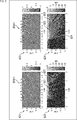
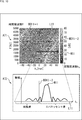
このような音の漏れ出しは、例えば図1に示すようにスピーカアレイを構成するスピーカの数が少ないほど多くなることが知られている。
なお、図1において横方向は空間上におけるスピーカアレイのスピーカが並ぶ方向を示しており、以下ではこの方向をx方向とも称する。また、図中、縦方向は空間上におけるx方向とは垂直な方向を示しており、以下ではこの方向をy方向とも称する。特にy方向は、スピーカアレイにより音が出力される方向と平行な方向である。
図1において、矢印A11に示す部分は、40個のスピーカからなるスピーカアレイSPA11を用いてエバネッセント波により音場を形成したときの、ある時刻における空間上の音の波面の様子を示している。ここでは各位置における濃淡は音波の振幅を示している。
また、矢印A12に示す部分は、スピーカアレイSPA11で矢印A11に示した音場を形成したときの空間上の各位置における音圧を示しており、特に各位置における濃淡が音圧を示している。
この例では、例えばスピーカアレイSPA11近傍にある矢印Q11に示す領域では音圧が大きく、十分に音声を聞き取ることができるようになっていることが分かる。これに対して、矢印Q11に示す領域から遠ざかると急激に音圧が下がり、音声が殆ど聞き取れなくなって局所音場が形成されていることが分かる。但し、この場合においても例えば矢印Q12に示す領域などでは、僅かに音が漏れ出していることが分かる。
これに対して、図1において矢印A13に示す部分は、20個のスピーカからなるスピーカアレイSPA12を用いてエバネッセント波により音場を形成したときの、ある時刻における空間上の音の波面の様子を示している。ここでは各位置における濃淡は音波の振幅を示している。
また、矢印A14に示す部分は、スピーカアレイSPA12で矢印A13に示した音場を形成したときの空間上の各位置における音圧を示しており、特に各位置における濃淡が音圧を示している。
この例では、例えばスピーカアレイSPA12近傍にある矢印Q13に示す領域では音圧が大きく、十分に音声を聞き取ることができるようになっていることが分かる。これに対して、矢印Q13に示す領域から遠ざかると音圧が下がっているが、例えば矢印Q14に示す領域や、矢印Q15に示す領域、矢印Q16に示す領域などでは、スピーカアレイSPA11における場合と比較して、音が多く漏れ出してしまっている。
このようにエバネッセント波で局所音場を形成する場合、スピーカアレイを構成するスピーカの数が少なくなるほど音の漏れ出しが多くなってしまう。
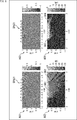
さらに、スピーカアレイのスピーカ数だけでなく、例えば図2に示すように、再生する音声の時間周波数の帯域によっても音の漏れ出しが多くなる。
なお、図2において図1における場合と対応する部分には同一の符号を付してあり、その説明は適宜省略する。また、図2において横方向は空間上におけるスピーカアレイSPA11のスピーカが並ぶ方向、すなわち上述したx方向を示しており、図中、縦方向は上述したy方向を示している。
図2において、矢印A21に示す部分は、スピーカアレイSPA11を用いてエバネッセント波により時間周波数が500Hzである音声を再生して音場を形成したときの、ある時刻における空間上の音の波面の様子を示している。ここでは各位置における濃淡は音波の振幅を示している。
また、矢印A22に示す部分は、スピーカアレイSPA11で矢印A21に示した音場を形成したときの空間上の各位置における音圧を示しており、特に各位置における濃淡が音圧を示している。
この例では、例えばスピーカアレイSPA11近傍にある矢印Q21に示す領域では音圧が大きく、十分に音声を聞き取ることができるようになっていることが分かる。これに対して、矢印Q21に示す領域から遠ざかると急激に音圧が下がり、音声が殆ど聞き取れなくなって局所音場が形成されていることが分かる。但し、この場合においても例えば矢印Q22に示す領域などでは、音が漏れ出していることが分かる。
これに対して、図2において、矢印A23に示す部分は、スピーカアレイSPA11を用いてエバネッセント波により時間周波数が1500Hzである音声を再生して音場を形成したときの、ある時刻における空間上の音の波面の様子を示している。ここでは各位置における濃淡は音波の振幅を示している。
また、矢印A24に示す部分は、スピーカアレイSPA11で矢印A23に示した音場を形成したときの空間上の各位置における音圧を示しており、特に各位置における濃淡が音圧を示している。
この例では、例えばスピーカアレイSPA11近傍にある矢印Q23に示す領域では音圧が大きく、十分に音声を聞き取ることができるようになっていることが分かる。これに対して、矢印Q23に示す領域から遠ざかると音圧が下がっているが、例えば矢印Q24に示す領域や矢印Q25に示す領域などでは、500Hzの音声を再生する場合と比較して、音が多く漏れ出してしまっている。
このようにエバネッセント波で局所音場を形成する場合、再生する音声の時間周波数が高いほど、つまり時間周波数の高域ほど音の漏れ出しが多くなってしまう。
そこで、本技術では、エバネッセント波を発生させるためのスピーカ駆動信号生成時における信号処理に加えて、指向性スピーカを含むスピーカアレイを用いることで、意図しない方向への音の漏れ出しを低減させることができるようにした。
ここで、指向性スピーカとは、例えば平面スピーカや平面波スピーカ、パラメトリックスピーカなどのスピーカであり、通常の無指向性スピーカよりも指向性が強いスピーカである。
例えば図3に示すように無指向性スピーカからなるスピーカアレイで音場を形成する場合について考える。なお、図3において横方向は上述した空間上におけるx方向を示しており、図中、縦方向は上述したy方向を示している。
矢印A31に示す部分は、無指向性スピーカSPK11を用いて音声を再生したときの空間上の各位置における音圧を示しており、特に各位置における濃淡が音圧を示している。この例から分かるように、無指向性スピーカSPK11を用いて音声を再生した場合、各方向の音圧が等しくなり、音の波面が全方向に広がって伝搬されている。
矢印A32に示す部分は、無指向性スピーカSPK11と同様のスピーカを複数並べて得られたスピーカアレイSPA21を用いてエバネッセント波により音場を形成したときの、ある時刻における空間上の音の波面の様子を示している。ここでは各位置における濃淡は音波の振幅を示している。
また、矢印A33に示す部分は、スピーカアレイSPA21で矢印A32に示した音場を形成したときの空間上の各位置における音圧を示しており、特に各位置における濃淡が音圧を示している。
この例では、例えばスピーカアレイSPA21近傍にある矢印Q31に示す領域では音圧が大きく、十分に音声を聞き取ることができるようになっていることが分かる。これに対して、矢印Q31に示す領域から遠ざかると急激に音圧が下がり、音声が殆ど聞き取れなくなって局所音場が形成されている。
しかし、例えば矢印Q32に示す領域や矢印Q33に示す領域などでは、音が漏れ出していることが分かる。特に、矢印Q33に示す領域など、スピーカアレイSPA21近傍のx方向側にある領域では音の漏れ出しが多いことが分かる。
これに対して、例えば図4に示すように指向性スピーカからなるスピーカアレイで音場を形成する場合について考える。なお、図4において横方向は上述した空間上におけるx方向を示しており、図中、縦方向は上述したy方向を示している。
矢印A41に示す部分は、指向性スピーカSPK21を用いて音声を再生したときの空間上の各位置における音圧を示しており、特に各位置における濃淡が音圧を示している。この例から分かるように、指向性スピーカSPK21を用いて音声を再生した場合、指向性スピーカSPK21前方の音圧が大きく、また指向性スピーカSPK21の右側および左側の音圧は極めて低くなっており、強い指向性を有する音波が伝搬されている。
矢印A42に示す部分は、指向性スピーカSPK21と同様のスピーカを複数並べて得られたスピーカアレイSPA31を用いてエバネッセント波により音場を形成したときの、ある時刻における空間上の音の波面の様子を示している。ここでは各位置における濃淡は音波の振幅を示している。
また、矢印A43に示す部分は、スピーカアレイSPA31で矢印A42に示した音場を形成したときの空間上の各位置における音圧を示しており、特に各位置における濃淡が音圧を示している。
この例では、例えばスピーカアレイSPA31近傍にある矢印Q41に示す領域では音圧が大きく、十分に音声を聞き取ることができるようになっていることが分かる。これに対して、矢印Q41に示す領域から遠ざかると急激に音圧が下がり、音声が殆ど聞き取れなくなって局所音場が形成されている。
指向性スピーカからなるスピーカアレイSPA31を用いたときでも、例えば矢印Q42に示す領域や矢印Q43に示す領域などでは音が漏れ出しているが、それでも図3を参照して説明した例と比較すると、音の漏れ出しは非常に少ないことが分かる。
このような指向性スピーカからなるスピーカアレイSPA31を用いれば、上述したスピーカ数が少ない場合や、高域の音声を再生する場合でも、十分に音の漏れ出しが抑制された局所音場を形成することができる。
換言すれば、本技術によれば、十分に音の漏れ出しを低減させることで、スピーカ数を削減したり、音の漏れ出しが十分に小さい状態で再生可能な時間周波数帯域をより高域へと拡張したりすることができるようになる。
例えば図3に示したスピーカアレイSPA21と、図4に示したスピーカアレイSPA31とを比較すると、スピーカ数が20個であり、再生する音声の時間周波数が500Hzであるときには、音の漏れ出しの状態は図5に示すようになる。
なお、図5において、図3または図4における場合と対応する部分には同一の符号を付してあり、その説明は省略する。また、図5において横方向は空間上におけるスピーカアレイSPA21またはスピーカアレイSPA31のスピーカが並ぶ方向、すなわち上述したx方向を示しており、図中、縦方向は上述したy方向を示している。
図5において、矢印A51に示す部分は、スピーカアレイSPA21を用いてエバネッセント波により時間周波数が500Hzである音声を再生して音場を形成したときの、ある時刻における空間上の音の波面の様子を示している。ここではスピーカアレイSPA21は20個の無指向性スピーカから構成されており、各位置における濃淡は音波の振幅を示している。
また、矢印A52に示す部分は、スピーカアレイSPA21で矢印A51に示した音場を形成したときの空間上の各位置における音圧を示しており、特に各位置における濃淡が音圧を示している。
この例では、スピーカアレイSPA21近傍の領域が局所音場で音声を再生したい領域となっているが、例えば矢印Q51乃至矢印Q53で示す領域など、音声を再生したい領域近傍だけでなく、比較的遠い位置の領域まで音が漏れ出してしまっている。
これに対して、矢印A53に示す部分は、スピーカアレイSPA31を用いてエバネッセント波により時間周波数が500Hzである音声を再生して音場を形成したときの、ある時刻における空間上の音の波面の様子を示している。ここではスピーカアレイSPA31は20個の指向性スピーカから構成されており、各位置における濃淡は音波の振幅を示している。
また、矢印A54に示す部分は、スピーカアレイSPA31で矢印A53に示した音場を形成したときの空間上の各位置における音圧を示しており、特に各位置における濃淡が音圧を示している。
この例では、スピーカアレイSPA31近傍の領域が局所音場で音声を再生したい領域となっているが、例えば矢印Q54や矢印Q55で示す領域など、音声を再生したい領域近傍で音が漏れ出してしまっている。しかし、スピーカアレイSPA31を用いた場合、スピーカアレイSPA21を用いた場合と比較すると、大幅に音の漏れ出しが低減されていることが分かる。すなわち、スピーカアレイを比較的少ない数のスピーカで構成したときでも、意図しない方向への音の漏れ出しを十分に抑制できていることが分かる。
同様に、例えばスピーカアレイSPA21と、スピーカアレイSPA31とを比較すると、スピーカ数が40個であり、再生する音声の時間周波数が1500Hzであるときには、音の漏れ出しの状態は図6に示すようになる。
なお、図6において、図5における場合と対応する部分には同一の符号を付してあり、その説明は省略する。また、図6において横方向は空間上におけるスピーカアレイSPA21またはスピーカアレイSPA31のスピーカが並ぶ方向、すなわち上述したx方向を示しており、図中、縦方向は上述したy方向を示している。
図6において、矢印A61に示す部分は、スピーカアレイSPA21を用いてエバネッセント波により時間周波数が1500Hzである音声を再生して音場を形成したときの、ある時刻における空間上の音の波面の様子を示している。ここではスピーカアレイSPA21は40個の無指向性スピーカから構成されており、各位置における濃淡は音波の振幅を示している。
また、矢印A62に示す部分は、スピーカアレイSPA21で矢印A61に示した音場を形成したときの空間上の各位置における音圧を示しており、特に各位置における濃淡が音圧を示している。
この例では、スピーカアレイSPA21近傍の領域が局所音場で音声を再生したい領域となっているが、例えば矢印Q61や矢印Q62で示す領域など、音声を再生したい領域近傍だけでなく、比較的遠い位置の領域まで広い領域で音が漏れ出している。
これに対して、矢印A63に示す部分は、スピーカアレイSPA31を用いてエバネッセント波により時間周波数が1500Hzである音声を再生して音場を形成したときの、ある時刻における空間上の音の波面の様子を示している。ここではスピーカアレイSPA31は40個の指向性スピーカから構成されており、各位置における濃淡は音波の振幅を示している。
また、矢印A64に示す部分は、スピーカアレイSPA31で矢印A63に示した音場を形成したときの空間上の各位置における音圧を示しており、特に各位置における濃淡が音圧を示している。
この例では、スピーカアレイSPA31近傍の領域が局所音場で音声を再生したい領域となっているが、例えば矢印Q63や矢印Q64で示す領域など、音声を再生したい領域近傍で音が漏れ出してしまっている。しかし、スピーカアレイSPA31を用いた場合、スピーカアレイSPA21を用いた場合と比較すると、大幅に音の漏れ出しが低減されていることが分かる。すなわち、高域の音声を再生したときでも、意図しない方向への音の漏れ出しを十分に抑制できていることが分かる。
以上のような本技術によれば、指向性スピーカを含むスピーカアレイと、エバネッセント波を発生させるためのスピーカ駆動信号生成時における信号処理とを組み合わせて局所音場の形成を行うことで、意図しない方向への音の漏れ出しを低減させることができる。特に、本技術によれば、スピーカアレイのスピーカ数が少ない場合や、高域の音声を再生する場合でも、十分に音の漏れ出しを抑制することができる。
なお、図4乃至図6を参照して説明した例では、スピーカアレイを構成するスピーカが全て指向性スピーカである場合について説明したが、スピーカアレイを構成するスピーカのうちの少なくとも一部を指向性スピーカとすればよい。
例えば指向性スピーカと無指向性スピーカとを組み合わせてスピーカアレイを構成する場合、スピーカアレイの右半分の部分を複数の無指向性スピーカにより構成し、残りの左半分を複数の指向性スピーカにより構成するようにしてもよい。また、例えば指向性スピーカと無指向性スピーカとを交互に並べてスピーカアレイを構成するようにしてもよい。
〈局所音場形成装置の構成例〉
続いて、以上において説明した本技術のより具体的な実施の形態について説明する。
続いて、以上において説明した本技術のより具体的な実施の形態について説明する。
図7は、本技術を適用した局所音場形成装置の構成例を示す図である。
図7に示す局所音場形成装置11は、局所音場形成フィルタ係数記録部21、フィルタ部22、およびスピーカアレイ23を有している。
局所音場形成フィルタ係数記録部21は、例えば不揮発性のメモリなどからなり、エバネッセント波を発生させて音場を形成することで局所音場を形成させるためのオーディオフィルタの係数を予め記録している。すなわち、局所音場形成フィルタ係数記録部21に記録されているオーディオフィルタ係数は、エバネッセント波により所望の音場を形成するための局所音場形成フィルタのためのフィルタ係数である。
局所音場形成フィルタ係数記録部21は、記録しているオーディオフィルタ係数をフィルタ部22に供給する。
フィルタ部22には、スピーカアレイ23により局所音場を形成する音声の音声信号である音源信号が供給される。フィルタ部22は、供給された音源信号に対して、局所音場形成フィルタ係数記録部21から供給されたオーディオフィルタ係数を用いたフィルタ処理を施すことで、スピーカアレイ23により局所音場を形成させるためのスピーカ駆動信号を生成する。フィルタ部22は、このようにして得られた各スピーカのスピーカ駆動信号をスピーカアレイ23に供給して音声を再生させる。
スピーカアレイ23は、複数のスピーカを直線状に並べて得られる直線スピーカアレイや、複数のスピーカを平面上に並べて得られる平面スピーカアレイなどからなり、フィルタ部22から供給されたスピーカ駆動信号に基づいて、音声を再生する。
これにより、スピーカアレイ23によってエバネッセント波が生成され、スピーカアレイ23近傍の領域でのみ音声を聞き取ることができる、局所音場が形成される。
なお、スピーカアレイ23は複数のスピーカから構成されているが、上述したように、それらの複数のスピーカのうちの少なくとも1以上のスピーカは、平面スピーカや、平面波スピーカ、パラメトリックスピーカなどの指向性スピーカとされている。つまり、スピーカアレイ23を構成する一部または全部のスピーカが指向性スピーカとなっている。
例えばスピーカアレイ23を構成するスピーカのうちの半分以上のスピーカを、平面スピーカや平面波スピーカなどの指向性スピーカとすることができる。
(局所音場形成フィルタ係数記録部)
次に、局所音場形成装置11の各部について、より詳細に説明する。
次に、局所音場形成装置11の各部について、より詳細に説明する。
まず、局所音場形成フィルタ係数記録部21について説明する。
例えば以下では、図8に示す3次元直交座標系で、3次元自由空間における音場の所定の位置Vが記述される場合について説明する。
図8に示す例では、スピーカアレイ23は平面スピーカアレイとされており、その平面スピーカアレイ上の所定の位置が3次元直交座標系であるxyz座標系の原点Oとされている。また、このxyz座標系では図中、横方向がx軸方向(x方向)とされ、図中、手前方向がy軸方向(y方向)とされ、図中、縦方向がz軸方向(z方向)とされている。
したがって、この例では任意の位置Vは、x座標、y座標、およびz座標を用いて位置V=(x,y,z)と表される。
特に、この例ではy方向がスピーカアレイ23を構成するスピーカが並ぶ方向と垂直な方向となっており、局所音場形成時には、y方向に減衰するエバネッセント波が発生するように、スピーカアレイ23により音声が再生される。
局所音場形成フィルタ係数記録部21には、y方向に減衰するエバネッセント波をスピーカアレイ23により生成するためのオーディオフィルタのフィルタ係数が記録されている。例えば、オーディオフィルタを構成するフィルタ係数は、以下のようにして求められる。
すなわち、3次元自由空間において、任意の位置Vにおける時刻tの音場p(V,t)は、次式(1)に示す波動方程式を満たす。

なお、式(1)においてcは音速を示しており、∇2は次式(2)に示す通りである。
また、時間フーリエ逆変換T(t)を次式(3)に示すものとすると、時間フーリエ変換F(・)は以下の式(4)に示すようになる。


なお、式(3)および式(4)において、iは虚数単位を示しており、ωは角周波数を示している。
ここで、上述した式(1)に対して、次式(5)に示すように変数分離を行って空間の微分と時間の微分を分けて、さらに式(4)を用いると、以下の式(6)に示すヘルムホルツ方程式が得られる。

なお、式(6)においてP(V,ω)は、位置Vにおける角周波数ωの音場を示している。また、角周波数がωpwであり、x方向、y方向、およびz方向のそれぞれの波数がkpw,x、kpw,y、およびkpw,zであるときの、角周波数ωpw、波数kpw,x、波数kpw,y、および波数kpw,zにより表される方向に伝搬する平面波を表す、式(6)に示すヘルムホルツ方程式の一般解は、次式(7)に示すものとなる。
なお、式(7)においてδ(ω-ωpw)はデルタ関数を示している。
ここで、波数領域では、次式(8)に示す関係が成立する。

式(8)をy方向の波数kpw,yについて解くと、次式(9)に示すようになる。

この式(9)の上段、つまり上側に示される波数kpw,yの波は通常の伝搬波を表しており、式(9)の下段、つまり下側に示される波数kpw,yの波はエバネッセント波を表している。
そこで、式(9)の下段に示されるエバネッセント波の波数kpw,yを式(7)に示した音場P(V,ω)に代入すると、次式(10)に示すようになる。

但し、波数kpw,yを式(7)に代入するにあたり、波数kpw,yの符号が正の項は物理的に意味をもたない解となるため、符号が負である項が代入されている。
また、式(10)における(kpw,x
2+kpw,z
2-(ω/c)2)1/2は、エバネッセント波の減衰の大きさを定める項である。
したがって、例えば角周波数ωに依存せず、一定の減衰の大きさとしたい場合には、減衰の大きさを表す定数αを用いて、次式(11)を満たすように波数kpw,xおよび波数kpw,zを設定すればよい。このとき、式(10)から分かるように定数αが大きいほど、エバネッセント波の減衰率が大きくなる。

ここで、式(10)で表されるエバネッセント波を生成するスピーカ駆動信号を得るためのオーディオフィルタの係数を求めることを考える。なお、オーディオフィルタの係数の求め方については、例えば「Itou et al. “EVANESCENT WAVE REPRODUCTION USING LINEAR ARRAY OF LOUDSPEAKERS,” in IEEE Workshop on Applications of Signal Processing to Audio and Acoustics (WASPAA), 2011.」などにも詳細に記載されている。
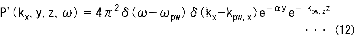
式(10)をxについて空間フーリエ変換すると、次式(12)に示すように表される。
また、伝達関数の空間周波数スペクトルG'(kx,y,z,ω)は、次式(13)に示すように表される。

なお、式(13)においてH0
(2)は第二種ハンケル関数を示しており、K0はベッセル関数を示している。
さらに、SDM(Spectral Division Method)法より、スピーカ駆動信号の空間周波数スペクトルD'(kx,ω)は次式(14)に示すようになる。なお、SDM法については、例えば「Jens Ahrens and Sascha Spors, “Sound Field Reproduction Using Planar and Linear Arrays of Loudspeakers,” in IEEE TRANSACTIONS ON AUDIO, SPEECH, AND LANGUAGE PROCESSING, VOL. 18, NO. 8, NOVEMBER 2010.」などに詳細に記載されている。
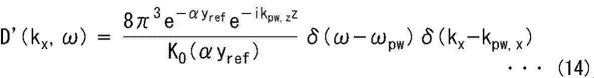
式(14)において、yrefはy方向における基準となる参照位置、すなわち制御点の位置を示している。
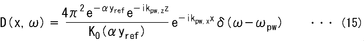
このようにして得られた式(14)を、波数kxについて逆空間フーリエ変換することで、次式(15)に示すスピーカ駆動信号の時間周波数スペクトルD(x,ω)が得られる。
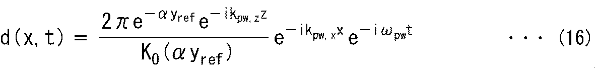
さらに、このようにして得られた時間周波数スペクトルD(x,ω)を逆時間フーリエ変換すると、次式(16)に示すようにスピーカ駆動信号の時間波形d(x,t)、すなわち時間信号であるスピーカ駆動信号d(x,t)が求まる。
このとき、スピーカアレイ23を構成するスピーカを識別し、そのスピーカの位置を示すインデックスをlとすると、以下の式(17)に示すように、式(16)からインデックスlのスピーカのオーディオフィルタのフィルタ係数h(l,m)が求まる。
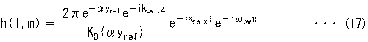
なお、式(17)において、mは時間インデックスを示している。このフィルタ係数h(l,m)は、式(16)に示したスピーカ駆動信号d(x,t)におけるxをインデックスlに置き換えるとともに、tを時間インデックスmに置き換えることにより得られる。このようなフィルタ係数h(l,m)を用いて音源信号にフィルタ処理を施すと、音源信号に基づいて形成される波面に対して空間方向に窓掛けが行われることになり、サイドローブ、つまり伝搬波の発生を低減させることができる。
また、以上においては、波数領域でエバネッセント波を求め、フィルタ係数h(l,m)を算出する方法について説明したが、これ以外の方法でエバネッセント波を生成するフィルタ係数を求めるようにしてもよい。
(フィルタ部)
フィルタ部22は、次式(18)に示す計算を行うことで、局所音場形成フィルタ係数記録部21から供給されるオーディオフィルタのフィルタ係数h(l,m)と音源信号とを畳み込み、スピーカアレイ23の各スピーカのスピーカ駆動信号s(l,n)を算出する。すなわち、音源信号に対して、フィルタ係数h(l,m)からなるオーディオフィルタを用いたフィルタ処理を施すことで、スピーカ駆動信号s(l,n)が生成される。
フィルタ部22は、次式(18)に示す計算を行うことで、局所音場形成フィルタ係数記録部21から供給されるオーディオフィルタのフィルタ係数h(l,m)と音源信号とを畳み込み、スピーカアレイ23の各スピーカのスピーカ駆動信号s(l,n)を算出する。すなわち、音源信号に対して、フィルタ係数h(l,m)からなるオーディオフィルタを用いたフィルタ処理を施すことで、スピーカ駆動信号s(l,n)が生成される。

なお、式(18)において、nは時間インデックスを示しており、x(n)は音源信号を示している。また、Nはフィルタ長を示している。
フィルタ部22は、このようにして得られたスピーカ駆動信号s(l,n)を、スピーカアレイ23を構成する各スピーカに供給し、音声を再生させる。
〈局所音場形成処理の説明〉
次に、図9のフローチャートを参照して、局所音場形成装置11により行われる局所音場形成処理について説明する。
次に、図9のフローチャートを参照して、局所音場形成装置11により行われる局所音場形成処理について説明する。
ステップS11において、フィルタ部22は、局所音場形成フィルタ係数記録部21から各スピーカのフィルタ係数h(l,m)を読み出して、スピーカごとに、読み出したフィルタ係数h(l,m)と、供給された音源信号とを畳み込み、スピーカ駆動信号s(l,n)を生成する。
ステップS11では、スピーカアレイ23を構成するスピーカごとに、上述した式(18)の計算が行われて、スピーカ駆動信号s(l,n)が生成される。
ステップS12において、フィルタ部22は、生成したスピーカ駆動信号s(l,n)をスピーカアレイ23を構成するスピーカに供給して音声を再生させ、局所音場形成処理は終了する。これにより、スピーカアレイ23によってエバネッセント波での音場形成が行われ、局所音場が形成される。
以上のように局所音場形成装置11は、空間方向の窓掛けを行うフィルタ係数を用いてスピーカ駆動信号を生成するとともに、指向性スピーカを構成要素として含むスピーカアレイ23でスピーカ駆動信号に基づく音声を再生させる。このようにすることで、意図しない方向への音の漏れ出しを低減させることができる。
ところで、フィルタ部22で得られたスピーカ駆動信号に基づいて、スピーカアレイ23で音声を再生する際に、特にスピーカアレイ23を構成するスピーカの数が少ない場合や、時間周波数の高域の音声を再生する場合にはx方向に伝搬波が漏れ出してしまう。
ここで、図10にエバネッセント波を生成するためのスピーカ駆動信号の空間スペクトルの例を示す。
図10では、矢印A71に示す部分は、スピーカ駆動信号の空間スペクトル、すなわち時空間スペクトログラムを示しており、特に横軸は空間周波数、つまりx方向の波数kxを示しており、縦軸は時間周波数fを示している。さらに、空間スペクトルにおける濃淡は音圧(振幅)を示している。
なお、ここでは説明を簡単にするためにz方向の波数kz=0とし、スピーカアレイ23を構成するスピーカは、x軸上に一直線に並べられているものとされている。
矢印A71に示す空間スペクトルにおいて、直線で表されている境界BD11-1および境界BD11-2は、エバネッセント領域と伝搬波領域との境界位置、つまりエバネッセント境界を表している。
局所音場形成装置11では、スピーカ駆動信号s(l,n)に基づいて音声を再生すると、矢印A71に示すような空間スペクトルの波面が生成されるが、生成される波には、エバネッセント波と伝搬波とが含まれている。
このとき、境界BD11-1よりも図中、右側かつ、境界BD11-2よりも図中、左側の領域が伝搬波領域であり、この伝搬波領域内の波が伝搬波となる。これに対して、エバネッセント境界の外側にあたる、境界BD11-1よりも図中、左側の領域と、境界BD11-2よりも図中、右側の領域とがエバネッセント領域であり、このエバネッセント領域内の波がエバネッセント波である。
なお、以下、境界BD11-1および境界BD11-2を特に区別する必要のない場合、単に境界BD11と称する。
境界BD11は、波数k=(kx
2+kz
2)1/2、特にこの例では波数kxがkx=|ω/c|となる位置であり、この位置の波はx方向に進む伝搬波となる。
また、矢印A72に示す部分は、矢印A71に示す空間スペクトルにおける所定領域、すなわち直線L11における部分の波数kxと、形成される波(音波)の振幅との関係を示している。すなわち、矢印A72に示す部分において縦軸は振幅を示しており、横軸は波数kxを示している。
図10に示す例では、矢印A71に示す空間スペクトルから分かるように、矢印W11に示す部分がスペクトルピークとして観測されている。すなわち、境界BD11-2に沿うようにスペクトルピークが存在し、このスペクトルピークはエバネッセント領域内に位置している。
したがって、矢印A72に示すように形成される波面における、矢印W11に示す部分、つまりスペクトルピーク部分がメインローブとなり、スピーカ駆動信号s(l,n)に基づいて音声を再生すると、主にエバネッセント波が生成されることが分かる。
このように、エバネッセント境界の外側にあたる、|ω/c|<|kx|となるエバネッセント領域にエバネッセント波を表すスペクトルのピークが存在するが、スピーカアレイ23のx方向の長さは有限長であるため打切り誤差が発生する。これにより、スペクトルのサイドローブがエバネッセント境界の内側にあたる、|kx|<|ω/c|となる伝搬波領域に漏れ出してしまい、エバネッセント波だけでなく、伝搬波も発生してしまうことが分かる。
上述したようにサイドローブの影響は、スピーカアレイ23を構成するスピーカの数が少ないほど大きく、また式(11)に示したαを定数とした場合、時間周波数の高域になるほどサイドローブの影響が大きくなる。
そこで、局所音場形成装置11では、スピーカアレイ23を構成するスピーカのなかの1以上のスピーカが指向性スピーカとされている。
例えばスピーカアレイ23を構成する1以上のスピーカとして、図4を参照して説明したように、正面方向、つまりy方向に指向性をもつ指向性スピーカを用いることで、x方向への音の漏れ出しを減少させることができる。
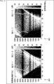
ここで、例えばスピーカアレイ23を構成するスピーカ全てをy方向に指向性をもつ指向性スピーカとすると、図11に示すように形成音場におけるエバネッセント境界付近の伝搬波領域のエネルギが小さくなる。
なお、図11において図10における場合と対応する部分には同一の符号を付してありその説明は適宜省略する。
図11において矢印A81に示す部分は、スピーカアレイ23を構成するスピーカを全て無指向性スピーカとしたときの形成された音場の空間スペクトル、すなわち時空間スペクトログラムを示している。また、矢印A82に示す部分は、スピーカアレイ23を構成するスピーカを全て指向性スピーカとしたときの形成された音場の空間スペクトル、すなわち時空間スペクトログラムを示している。特に、これらの空間スペクトルにおいて、横軸は空間周波数、つまり波数kxを示しており、縦軸は時間周波数fを示している。さらに、空間スペクトルにおける濃淡は音圧(エネルギ)を示している。
矢印A81に示す空間スペクトルでは、境界BD11近傍における伝搬波領域のエネルギが大きく、x方向、つまりスピーカアレイ23におけるスピーカが並んでいる方向へと伝搬する平面波(伝搬波)が発生してしまう。つまり、スピーカアレイ23に対してx方向への音の漏れ出しが多くなってしまう。
これに対して、矢印A82に示す空間スペクトルでは、境界BD11近傍における伝搬波領域のエネルギが小さく、x方向への音の漏れ出しが大きく低減されていることが分かる。これは、指向性スピーカを用いることで境界BD11近傍、つまりエバネッセント境界付近に漏れ出すサイドローブの影響が小さくなるからである。
また、スピーカアレイ23を構成するスピーカに指向性スピーカを採用すると、x方向への音の漏れ出しが少なくなる現象は、例えば図12に示すように、スピーカアレイ23の伝達特性の時空間スペクトログラムでも確認することができる。なお、図12において図10における場合と対応する部分には同一の符号を付してありその説明は適宜省略する。
図12において矢印A91に示す部分は、スピーカアレイ23を構成するスピーカを全て無指向性スピーカとしたときの、スピーカアレイ23の伝達特性の時空間スペクトログラム、すなわち空間スペクトルを示している。また、矢印A92に示す部分は、スピーカアレイ23を構成するスピーカを全て指向性スピーカとしたときの、スピーカアレイ23の伝達特性の時空間スペクトログラム、すなわち空間スペクトルを示している。特に、これらの空間スペクトルにおいて、横軸は空間周波数、つまり波数kxを示しており、縦軸は時間周波数fを示している。さらに、空間スペクトルにおける濃淡は音圧(エネルギ)を示している。
矢印A91に示す空間スペクトルでは、境界BD11であるエバネッセント境界付近の伝搬波領域、つまりx方向へ伝搬する信号が一定のエネルギを持っていることが分かる。
これに対して、矢印A92に示す空間スペクトルでは、境界BD11であるエバネッセント境界付近の伝搬波領域において、矢印A91に示す空間スペクトルにおける場合と比べて同じ領域でも信号のエネルギがより小さくなっていることが分かる。
以上のように、スピーカアレイ23を構成するスピーカのうちの1以上のスピーカを、指向性スピーカとすることで、無指向性スピーカのみからなるスピーカアレイを用いる場合よりも、意図しない方向への音の漏れ出しを大幅に低減させることができる。
〈コンピュータの構成例〉
ところで、上述した一連の処理は、ハードウェアにより実行することもできるし、ソフトウェアにより実行することもできる。一連の処理をソフトウェアにより実行する場合には、そのソフトウェアを構成するプログラムが、コンピュータにインストールされる。ここで、コンピュータには、専用のハードウェアに組み込まれているコンピュータや、各種のプログラムをインストールすることで、各種の機能を実行することが可能な、例えば汎用のコンピュータなどが含まれる。
ところで、上述した一連の処理は、ハードウェアにより実行することもできるし、ソフトウェアにより実行することもできる。一連の処理をソフトウェアにより実行する場合には、そのソフトウェアを構成するプログラムが、コンピュータにインストールされる。ここで、コンピュータには、専用のハードウェアに組み込まれているコンピュータや、各種のプログラムをインストールすることで、各種の機能を実行することが可能な、例えば汎用のコンピュータなどが含まれる。
図13は、上述した一連の処理をプログラムにより実行するコンピュータのハードウェアの構成例を示すブロック図である。
コンピュータにおいて、CPU(Central Processing Unit)501,ROM(Read Only Memory)502,RAM(Random Access Memory)503は、バス504により相互に接続されている。
バス504には、さらに、入出力インターフェース505が接続されている。入出力インターフェース505には、入力部506、出力部507、記録部508、通信部509、及びドライブ510が接続されている。
入力部506は、キーボード、マウス、マイクロホン、撮像素子などよりなる。出力部507は、ディスプレイ、スピーカアレイなどよりなる。記録部508は、ハードディスクや不揮発性のメモリなどよりなる。通信部509は、ネットワークインターフェースなどよりなる。ドライブ510は、磁気ディスク、光ディスク、光磁気ディスク、又は半導体メモリなどのリムーバブル記録媒体511を駆動する。
以上のように構成されるコンピュータでは、CPU501が、例えば、記録部508に記録されているプログラムを、入出力インターフェース505及びバス504を介して、RAM503にロードして実行することにより、上述した一連の処理が行われる。
コンピュータ(CPU501)が実行するプログラムは、例えば、パッケージメディア等としてのリムーバブル記録媒体511に記録して提供することができる。また、プログラムは、ローカルエリアネットワーク、インターネット、デジタル衛星放送といった、有線または無線の伝送媒体を介して提供することができる。
コンピュータでは、プログラムは、リムーバブル記録媒体511をドライブ510に装着することにより、入出力インターフェース505を介して、記録部508にインストールすることができる。また、プログラムは、有線または無線の伝送媒体を介して、通信部509で受信し、記録部508にインストールすることができる。その他、プログラムは、ROM502や記録部508に、あらかじめインストールしておくことができる。
なお、コンピュータが実行するプログラムは、本明細書で説明する順序に沿って時系列に処理が行われるプログラムであっても良いし、並列に、あるいは呼び出しが行われたとき等の必要なタイミングで処理が行われるプログラムであっても良い。
また、本技術の実施の形態は、上述した実施の形態に限定されるものではなく、本技術の要旨を逸脱しない範囲において種々の変更が可能である。
例えば、本技術は、1つの機能をネットワークを介して複数の装置で分担、共同して処理するクラウドコンピューティングの構成をとることができる。
また、上述のフローチャートで説明した各ステップは、1つの装置で実行する他、複数の装置で分担して実行することができる。
さらに、1つのステップに複数の処理が含まれる場合には、その1つのステップに含まれる複数の処理は、1つの装置で実行する他、複数の装置で分担して実行することができる。
また、本明細書中に記載された効果はあくまで例示であって限定されるものではなく、他の効果があってもよい。
さらに、本技術は、以下の構成とすることも可能である。
(1)
エバネッセント波により音場を形成するためのオーディオフィルタ係数を記録する局所音場形成フィルタ係数記録部と、
前記オーディオフィルタ係数と音源信号とを畳み込んでスピーカ駆動信号を生成するフィルタ部と、
指向性スピーカを含む複数のスピーカから構成され、前記スピーカ駆動信号に基づいて音を再生するスピーカアレイと
を備える局所音場形成装置。
(2)
前記指向性スピーカは、平面スピーカ、または平面波スピーカである
(1)に記載の局所音場形成装置。
(3)
前記スピーカアレイは、直線スピーカアレイ、または平面スピーカアレイである
(1)または(2)に記載の局所音場形成装置。
(4)
前記スピーカアレイを構成する前記複数の前記スピーカのうちの半分以上の前記スピーカが前記指向性スピーカである
(1)乃至(3)の何れか一項に記載の局所音場形成装置。
(5)
エバネッセント波により音場を形成するためのオーディオフィルタ係数を記録する局所音場形成フィルタ係数記録部と、
前記オーディオフィルタ係数と音源信号とを畳み込んでスピーカ駆動信号を生成するフィルタ部と、
指向性スピーカを含む複数のスピーカから構成され、前記スピーカ駆動信号に基づいて音を再生するスピーカアレイと
を備える局所音場形成装置の局所音場形成方法であって、
前記フィルタ部が前記スピーカ駆動信号を生成し、
前記スピーカアレイが前記スピーカ駆動信号に基づいて音を再生する
ステップを含む局所音場形成方法。
(6)
エバネッセント波により音場を形成するためのオーディオフィルタ係数を記録する局所音場形成フィルタ係数記録部と、
前記オーディオフィルタ係数と音源信号とを畳み込んでスピーカ駆動信号を生成するフィルタ部と、
指向性スピーカを含む複数のスピーカから構成され、前記スピーカ駆動信号に基づいて音を再生するスピーカアレイと
を備える局所音場形成装置を制御するコンピュータに、
前記フィルタ部により前記スピーカ駆動信号を生成させ、
前記スピーカアレイにより前記スピーカ駆動信号に基づいて音を再生させる
ステップを含む処理を実行させるプログラム。
エバネッセント波により音場を形成するためのオーディオフィルタ係数を記録する局所音場形成フィルタ係数記録部と、
前記オーディオフィルタ係数と音源信号とを畳み込んでスピーカ駆動信号を生成するフィルタ部と、
指向性スピーカを含む複数のスピーカから構成され、前記スピーカ駆動信号に基づいて音を再生するスピーカアレイと
を備える局所音場形成装置。
(2)
前記指向性スピーカは、平面スピーカ、または平面波スピーカである
(1)に記載の局所音場形成装置。
(3)
前記スピーカアレイは、直線スピーカアレイ、または平面スピーカアレイである
(1)または(2)に記載の局所音場形成装置。
(4)
前記スピーカアレイを構成する前記複数の前記スピーカのうちの半分以上の前記スピーカが前記指向性スピーカである
(1)乃至(3)の何れか一項に記載の局所音場形成装置。
(5)
エバネッセント波により音場を形成するためのオーディオフィルタ係数を記録する局所音場形成フィルタ係数記録部と、
前記オーディオフィルタ係数と音源信号とを畳み込んでスピーカ駆動信号を生成するフィルタ部と、
指向性スピーカを含む複数のスピーカから構成され、前記スピーカ駆動信号に基づいて音を再生するスピーカアレイと
を備える局所音場形成装置の局所音場形成方法であって、
前記フィルタ部が前記スピーカ駆動信号を生成し、
前記スピーカアレイが前記スピーカ駆動信号に基づいて音を再生する
ステップを含む局所音場形成方法。
(6)
エバネッセント波により音場を形成するためのオーディオフィルタ係数を記録する局所音場形成フィルタ係数記録部と、
前記オーディオフィルタ係数と音源信号とを畳み込んでスピーカ駆動信号を生成するフィルタ部と、
指向性スピーカを含む複数のスピーカから構成され、前記スピーカ駆動信号に基づいて音を再生するスピーカアレイと
を備える局所音場形成装置を制御するコンピュータに、
前記フィルタ部により前記スピーカ駆動信号を生成させ、
前記スピーカアレイにより前記スピーカ駆動信号に基づいて音を再生させる
ステップを含む処理を実行させるプログラム。
11 局所音場形成装置, 21 局所音場形成フィルタ係数記録部, 22 フィルタ部, 23 スピーカアレイ
Claims (6)
- エバネッセント波により音場を形成するためのオーディオフィルタ係数を記録する局所音場形成フィルタ係数記録部と、
前記オーディオフィルタ係数と音源信号とを畳み込んでスピーカ駆動信号を生成するフィルタ部と、
指向性スピーカを含む複数のスピーカから構成され、前記スピーカ駆動信号に基づいて音を再生するスピーカアレイと
を備える局所音場形成装置。 - 前記指向性スピーカは、平面スピーカ、または平面波スピーカである
請求項1に記載の局所音場形成装置。 - 前記スピーカアレイは、直線スピーカアレイ、または平面スピーカアレイである
請求項1に記載の局所音場形成装置。 - 前記スピーカアレイを構成する前記複数の前記スピーカのうちの半分以上の前記スピーカが前記指向性スピーカである
請求項1に記載の局所音場形成装置。 - エバネッセント波により音場を形成するためのオーディオフィルタ係数を記録する局所音場形成フィルタ係数記録部と、
前記オーディオフィルタ係数と音源信号とを畳み込んでスピーカ駆動信号を生成するフィルタ部と、
指向性スピーカを含む複数のスピーカから構成され、前記スピーカ駆動信号に基づいて音を再生するスピーカアレイと
を備える局所音場形成装置の局所音場形成方法であって、
前記フィルタ部が前記スピーカ駆動信号を生成し、
前記スピーカアレイが前記スピーカ駆動信号に基づいて音を再生する
ステップを含む局所音場形成方法。 - エバネッセント波により音場を形成するためのオーディオフィルタ係数を記録する局所音場形成フィルタ係数記録部と、
前記オーディオフィルタ係数と音源信号とを畳み込んでスピーカ駆動信号を生成するフィルタ部と、
指向性スピーカを含む複数のスピーカから構成され、前記スピーカ駆動信号に基づいて音を再生するスピーカアレイと
を備える局所音場形成装置を制御するコンピュータに、
前記フィルタ部により前記スピーカ駆動信号を生成させ、
前記スピーカアレイにより前記スピーカ駆動信号に基づいて音を再生させる
ステップを含む処理を実行させるプログラム。
Priority Applications (4)
| Application Number | Priority Date | Filing Date | Title |
|---|---|---|---|
| EP17806377.2A EP3468224A4 (en) | 2016-05-30 | 2017-05-17 | DEVICE FOR FORMING A LOCAL SOUND FIELD, METHOD FOR FORMING A LOCAL SOUND FIELD AND PROGRAM |
| JP2018520781A JP6904344B2 (ja) | 2016-05-30 | 2017-05-17 | 局所音場形成装置および方法、並びにプログラム |
| CN201780031946.6A CN109155885A (zh) | 2016-05-30 | 2017-05-17 | 局部声场形成装置、局部声场形成方法和程序 |
| US16/301,087 US10708686B2 (en) | 2016-05-30 | 2017-05-17 | Local sound field forming apparatus and local sound field forming method |
Applications Claiming Priority (2)
| Application Number | Priority Date | Filing Date | Title |
|---|---|---|---|
| JP2016-107355 | 2016-05-30 | ||
| JP2016107355 | 2016-05-30 |
Publications (1)
| Publication Number | Publication Date |
|---|---|
| WO2017208819A1 true WO2017208819A1 (ja) | 2017-12-07 |
Family
ID=60478508
Family Applications (1)
| Application Number | Title | Priority Date | Filing Date |
|---|---|---|---|
| PCT/JP2017/018498 WO2017208819A1 (ja) | 2016-05-30 | 2017-05-17 | 局所音場形成装置および方法、並びにプログラム |
Country Status (5)
| Country | Link |
|---|---|
| US (1) | US10708686B2 (ja) |
| EP (1) | EP3468224A4 (ja) |
| JP (1) | JP6904344B2 (ja) |
| CN (1) | CN109155885A (ja) |
| WO (1) | WO2017208819A1 (ja) |
Families Citing this family (6)
| Publication number | Priority date | Publication date | Assignee | Title |
|---|---|---|---|---|
| IL243513B2 (en) * | 2016-01-07 | 2023-11-01 | Noveto Systems Ltd | A system and method for voice communication |
| US11388541B2 (en) | 2016-01-07 | 2022-07-12 | Noveto Systems Ltd. | Audio communication system and method |
| US10952008B2 (en) | 2017-01-05 | 2021-03-16 | Noveto Systems Ltd. | Audio communication system and method |
| US10764707B1 (en) * | 2019-01-29 | 2020-09-01 | Facebook Technologies, Llc | Systems, methods, and devices for producing evancescent audio waves |
| US11825288B2 (en) | 2021-01-21 | 2023-11-21 | Biamp Systems, LLC | Loudspeaker array passive acoustic configuration procedure |
| CN117375577B (zh) * | 2023-12-06 | 2024-03-12 | 中国空气动力研究与发展中心计算空气动力研究所 | 声传播问题的数值滤波方法、装置、电子设备及存储介质 |
Citations (3)
| Publication number | Priority date | Publication date | Assignee | Title |
|---|---|---|---|---|
| JP2012008156A (ja) * | 2010-06-22 | 2012-01-12 | Nippon Telegr & Teleph Corp <Ntt> | 局所再生システム |
| JP2012044572A (ja) | 2010-08-23 | 2012-03-01 | Nippon Telegr & Teleph Corp <Ntt> | 局所再生方法、局所再生装置及びそのプログラム |
| JP2012175679A (ja) * | 2011-02-24 | 2012-09-10 | Nippon Telegr & Teleph Corp <Ntt> | 局所再生装置とフィルタ係数決定装置とそれらの方法と、プログラム |
Family Cites Families (26)
| Publication number | Priority date | Publication date | Assignee | Title |
|---|---|---|---|---|
| US6674864B1 (en) * | 1997-12-23 | 2004-01-06 | Ati Technologies | Adaptive speaker compensation system for a multimedia computer system |
| US6546105B1 (en) * | 1998-10-30 | 2003-04-08 | Matsushita Electric Industrial Co., Ltd. | Sound image localization device and sound image localization method |
| EP1855506A2 (en) * | 1999-09-29 | 2007-11-14 | 1...Limited | Method and apparatus to direct sound using an array of output transducers |
| US7684577B2 (en) * | 2001-05-28 | 2010-03-23 | Mitsubishi Denki Kabushiki Kaisha | Vehicle-mounted stereophonic sound field reproducer |
| US20040114770A1 (en) * | 2002-10-30 | 2004-06-17 | Pompei Frank Joseph | Directed acoustic sound system |
| WO2004047490A1 (ja) * | 2002-11-15 | 2004-06-03 | Sony Corporation | オーディオ信号の処理方法及び処理装置 |
| JP4551652B2 (ja) * | 2003-12-02 | 2010-09-29 | ソニー株式会社 | 音場再生装置及び音場空間再生システム |
| KR101086398B1 (ko) * | 2003-12-24 | 2011-11-25 | 삼성전자주식회사 | 다수의 마이크로폰을 이용한 지향성 제어 가능 스피커시스템 및 그 방법 |
| US8243935B2 (en) * | 2005-06-30 | 2012-08-14 | Panasonic Corporation | Sound image localization control apparatus |
| JP2007142875A (ja) * | 2005-11-18 | 2007-06-07 | Sony Corp | 音響特性補正装置 |
| KR100739798B1 (ko) * | 2005-12-22 | 2007-07-13 | 삼성전자주식회사 | 청취 위치를 고려한 2채널 입체음향 재생 방법 및 장치 |
| US20080118074A1 (en) * | 2006-11-22 | 2008-05-22 | Shuichi Takada | Stereophonic sound control apparatus and stereophonic sound control method |
| US8270616B2 (en) * | 2007-02-02 | 2012-09-18 | Logitech Europe S.A. | Virtual surround for headphones and earbuds headphone externalization system |
| JP4924119B2 (ja) * | 2007-03-12 | 2012-04-25 | ヤマハ株式会社 | アレイスピーカ装置 |
| JP2008301200A (ja) * | 2007-05-31 | 2008-12-11 | Nec Electronics Corp | 音声処理装置 |
| GB0821327D0 (en) * | 2008-11-21 | 2008-12-31 | Airsound Llp | Apparatus for reproduction of sound |
| US20110274283A1 (en) * | 2009-07-22 | 2011-11-10 | Lewis Athanas | Open Air Noise Cancellation |
| WO2011028891A2 (en) * | 2009-09-02 | 2011-03-10 | National Semiconductor Corporation | Beam forming in spatialized audio sound systems using distributed array filters |
| EP2566190A4 (en) * | 2010-04-26 | 2013-10-16 | Toa Corp | SPEAKER AND FILTER COEFFICIENT GENERATOR |
| JP5696427B2 (ja) * | 2010-10-22 | 2015-04-08 | ソニー株式会社 | ヘッドフォン装置 |
| JP5486567B2 (ja) * | 2010-12-21 | 2014-05-07 | 日本電信電話株式会社 | 狭指向音声再生処理方法、装置、プログラム |
| GB201101909D0 (en) * | 2011-02-04 | 2011-03-23 | Rolls Royce Plc | A method of tip grinding the blades of a gas turbine rotor |
| EP2692151B1 (en) * | 2011-03-30 | 2018-01-10 | Kaetel Systems GmbH | Electret microphone |
| JP5862073B2 (ja) * | 2011-06-30 | 2016-02-16 | 株式会社ニコン | 撮像装置 |
| US9591402B2 (en) * | 2011-07-18 | 2017-03-07 | Hewlett-Packard Development Company, L.P. | Transmit audio in a target space |
| DK2863654T3 (en) * | 2013-10-17 | 2018-10-22 | Oticon As | Method for reproducing an acoustic sound field |
-
2017
- 2017-05-17 JP JP2018520781A patent/JP6904344B2/ja active Active
- 2017-05-17 EP EP17806377.2A patent/EP3468224A4/en not_active Withdrawn
- 2017-05-17 WO PCT/JP2017/018498 patent/WO2017208819A1/ja unknown
- 2017-05-17 CN CN201780031946.6A patent/CN109155885A/zh active Pending
- 2017-05-17 US US16/301,087 patent/US10708686B2/en active Active
Patent Citations (3)
| Publication number | Priority date | Publication date | Assignee | Title |
|---|---|---|---|---|
| JP2012008156A (ja) * | 2010-06-22 | 2012-01-12 | Nippon Telegr & Teleph Corp <Ntt> | 局所再生システム |
| JP2012044572A (ja) | 2010-08-23 | 2012-03-01 | Nippon Telegr & Teleph Corp <Ntt> | 局所再生方法、局所再生装置及びそのプログラム |
| JP2012175679A (ja) * | 2011-02-24 | 2012-09-10 | Nippon Telegr & Teleph Corp <Ntt> | 局所再生装置とフィルタ係数決定装置とそれらの方法と、プログラム |
Non-Patent Citations (4)
| Title |
|---|
| HIROAKI ITO ET AL.: "A study of acoustic evanescent wave reproduction using linear loudspeaker array", REPORT OF THE 2011 SPRING MEETING, THE ACOUSTICAL SOCIETY OF JAPAN CD-ROM, March 2011 (2011-03-01), pages 947 - 948, XP009511320 * |
| ITOU ET AL.: "EVANESCENT WAVE REPRODUCTION USING LINEAR ARRAY OF LOUDSPEAKERS", IEEE WORKSHOP ON APPLICATIONS OF SIGNAL PROCESSING TO AUDIO AND ACOUSTICS (WASPAA, 2011 |
| JENS AHRENS; SASCHA SPORS: "Sound Field Reproduction Using Planar and Linear Arrays of loudspeakers", IEEE TRANSACTIONS ON AUDIO, SPEECH, AND LANGUAGE PROCESSING, vol. 18, no. 8, November 2010 (2010-11-01) |
| See also references of EP3468224A4 * |
Also Published As
| Publication number | Publication date |
|---|---|
| US20190191241A1 (en) | 2019-06-20 |
| JPWO2017208819A1 (ja) | 2019-03-28 |
| JP6904344B2 (ja) | 2021-07-14 |
| EP3468224A4 (en) | 2019-06-12 |
| CN109155885A (zh) | 2019-01-04 |
| EP3468224A1 (en) | 2019-04-10 |
| US10708686B2 (en) | 2020-07-07 |
Similar Documents
| Publication | Publication Date | Title |
|---|---|---|
| WO2017208819A1 (ja) | 局所音場形成装置および方法、並びにプログラム | |
| JP6933215B2 (ja) | 音場形成装置および方法、並びにプログラム | |
| US10880638B2 (en) | Sound field forming apparatus and method | |
| CN108370487A (zh) | 声音处理设备、方法和程序 | |
| US20140205100A1 (en) | Method and an apparatus for generating an acoustic signal with an enhanced spatial effect | |
| JPWO2016056410A1 (ja) | 音声処理装置および方法、並びにプログラム | |
| US9966081B2 (en) | Method and apparatus for synthesizing separated sound source | |
| JP7036008B2 (ja) | 局所消音音場形成装置および方法、並びにプログラム | |
| US10582329B2 (en) | Audio processing device and method | |
| WO2019168083A1 (ja) | 音響信号処理装置、音響信号処理方法および音響信号処理プログラム | |
| JP7010231B2 (ja) | 信号処理装置および方法、並びにプログラム | |
| Yanagidate et al. | Car cabin personal audio: Acoustic contrast with limited sound differences | |
| JP7099456B2 (ja) | スピーカアレイ、および信号処理装置 | |
| EP3787311A1 (en) | Sound image reproduction device, sound image reproduction method and sound image reproduction program | |
| JP5941373B2 (ja) | スピーカアレイ駆動装置およびスピーカアレイ駆動方法 | |
| US11871211B2 (en) | Signal processing apparatus, signal processing method, and signal processing program |
Legal Events
| Date | Code | Title | Description |
|---|---|---|---|
| ENP | Entry into the national phase |
Ref document number: 2018520781 Country of ref document: JP Kind code of ref document: A |
|
| NENP | Non-entry into the national phase |
Ref country code: DE |
|
| 121 | Ep: the epo has been informed by wipo that ep was designated in this application |
Ref document number: 17806377 Country of ref document: EP Kind code of ref document: A1 |
|
| ENP | Entry into the national phase |
Ref document number: 2017806377 Country of ref document: EP Effective date: 20190102 |