WO2017208531A1 - 二次電池 - Google Patents
二次電池 Download PDFInfo
- Publication number
- WO2017208531A1 WO2017208531A1 PCT/JP2017/007222 JP2017007222W WO2017208531A1 WO 2017208531 A1 WO2017208531 A1 WO 2017208531A1 JP 2017007222 W JP2017007222 W JP 2017007222W WO 2017208531 A1 WO2017208531 A1 WO 2017208531A1
- Authority
- WO
- WIPO (PCT)
- Prior art keywords
- curved surface
- negative electrode
- positive electrode
- electrode
- secondary battery
- Prior art date
- Legal status (The legal status is an assumption and is not a legal conclusion. Google has not performed a legal analysis and makes no representation as to the accuracy of the status listed.)
- Ceased
Links
Images


Classifications
-
- H—ELECTRICITY
- H01—ELECTRIC ELEMENTS
- H01M—PROCESSES OR MEANS, e.g. BATTERIES, FOR THE DIRECT CONVERSION OF CHEMICAL ENERGY INTO ELECTRICAL ENERGY
- H01M10/00—Secondary cells; Manufacture thereof
- H01M10/05—Accumulators with non-aqueous electrolyte
- H01M10/058—Construction or manufacture
- H01M10/0585—Construction or manufacture of accumulators having only flat construction elements, i.e. flat positive electrodes, flat negative electrodes and flat separators
-
- H—ELECTRICITY
- H01—ELECTRIC ELEMENTS
- H01M—PROCESSES OR MEANS, e.g. BATTERIES, FOR THE DIRECT CONVERSION OF CHEMICAL ENERGY INTO ELECTRICAL ENERGY
- H01M10/00—Secondary cells; Manufacture thereof
- H01M10/05—Accumulators with non-aqueous electrolyte
- H01M10/052—Li-accumulators
- H01M10/0525—Rocking-chair batteries, i.e. batteries with lithium insertion or intercalation in both electrodes; Lithium-ion batteries
-
- H—ELECTRICITY
- H01—ELECTRIC ELEMENTS
- H01M—PROCESSES OR MEANS, e.g. BATTERIES, FOR THE DIRECT CONVERSION OF CHEMICAL ENERGY INTO ELECTRICAL ENERGY
- H01M4/00—Electrodes
- H01M4/02—Electrodes composed of, or comprising, active material
- H01M4/13—Electrodes for accumulators with non-aqueous electrolyte, e.g. for lithium-accumulators; Processes of manufacture thereof
- H01M4/131—Electrodes based on mixed oxides or hydroxides, or on mixtures of oxides or hydroxides, e.g. LiCoOx
-
- H—ELECTRICITY
- H01—ELECTRIC ELEMENTS
- H01M—PROCESSES OR MEANS, e.g. BATTERIES, FOR THE DIRECT CONVERSION OF CHEMICAL ENERGY INTO ELECTRICAL ENERGY
- H01M4/00—Electrodes
- H01M4/02—Electrodes composed of, or comprising, active material
- H01M4/13—Electrodes for accumulators with non-aqueous electrolyte, e.g. for lithium-accumulators; Processes of manufacture thereof
- H01M4/133—Electrodes based on carbonaceous material, e.g. graphite-intercalation compounds or CFx
-
- H—ELECTRICITY
- H01—ELECTRIC ELEMENTS
- H01M—PROCESSES OR MEANS, e.g. BATTERIES, FOR THE DIRECT CONVERSION OF CHEMICAL ENERGY INTO ELECTRICAL ENERGY
- H01M50/00—Constructional details or processes of manufacture of the non-active parts of electrochemical cells other than fuel cells, e.g. hybrid cells
- H01M50/10—Primary casings; Jackets or wrappings
- H01M50/102—Primary casings; Jackets or wrappings characterised by their shape or physical structure
- H01M50/105—Pouches or flexible bags
-
- Y—GENERAL TAGGING OF NEW TECHNOLOGICAL DEVELOPMENTS; GENERAL TAGGING OF CROSS-SECTIONAL TECHNOLOGIES SPANNING OVER SEVERAL SECTIONS OF THE IPC; TECHNICAL SUBJECTS COVERED BY FORMER USPC CROSS-REFERENCE ART COLLECTIONS [XRACs] AND DIGESTS
- Y02—TECHNOLOGIES OR APPLICATIONS FOR MITIGATION OR ADAPTATION AGAINST CLIMATE CHANGE
- Y02E—REDUCTION OF GREENHOUSE GAS [GHG] EMISSIONS, RELATED TO ENERGY GENERATION, TRANSMISSION OR DISTRIBUTION
- Y02E60/00—Enabling technologies; Technologies with a potential or indirect contribution to GHG emissions mitigation
- Y02E60/10—Energy storage using batteries
-
- Y—GENERAL TAGGING OF NEW TECHNOLOGICAL DEVELOPMENTS; GENERAL TAGGING OF CROSS-SECTIONAL TECHNOLOGIES SPANNING OVER SEVERAL SECTIONS OF THE IPC; TECHNICAL SUBJECTS COVERED BY FORMER USPC CROSS-REFERENCE ART COLLECTIONS [XRACs] AND DIGESTS
- Y02—TECHNOLOGIES OR APPLICATIONS FOR MITIGATION OR ADAPTATION AGAINST CLIMATE CHANGE
- Y02P—CLIMATE CHANGE MITIGATION TECHNOLOGIES IN THE PRODUCTION OR PROCESSING OF GOODS
- Y02P70/00—Climate change mitigation technologies in the production process for final industrial or consumer products
- Y02P70/50—Manufacturing or production processes characterised by the final manufactured product
Definitions
- the present invention relates to a secondary battery.
- Secondary batteries that can be repeatedly charged and discharged have been used for various purposes.
- the secondary battery is used as a power source for electronic devices such as smartphones and notebook computers.
- the secondary battery has a structure in which an electrode assembly and an electrolyte are accommodated and enclosed in an exterior body.
- the electrode assembly includes a positive electrode, a negative electrode, and a separator disposed between the positive electrode and the negative electrode.
- the electrode assembly has a planar laminated structure in which a plurality of unit electrode units including a positive electrode, a negative electrode, and a separator are laminated.
- some of the positive electrode and the negative electrode have curved surfaces adjacent to part of the contour surface in plan view.
- the negative electrode is disposed so as to protrude from the positive electrode so that a gap is formed between the positive electrode and the negative electrode in plan view.
- the gap between the positive electrode and the negative electrode in a plan view is relatively large, the portion that is not used as the negative electrode increases, and as a result, the energy density of the secondary battery may be reduced.
- An object of the present invention is to provide a secondary battery capable of suppressing a decrease in energy density.
- An electrode assembly including a positive electrode, a negative electrode, and a separator disposed between the positive electrode and the negative electrode, and an electrolyte, and a secondary battery in which an electrolyte is housed,
- Each of the positive electrode and the negative electrode has curved surfaces adjacent to part of the contour surface in plan view, and the negative electrode is more positive than the positive electrode so that a gap G is formed between the positive electrode and the negative electrode in plan view.
- a secondary battery is also provided, which is characterized by referring to lengths that are equidistant.
- the function of the secondary battery can be suitably exhibited.
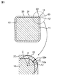
- FIG. 1 is a schematic plan view showing a positional relationship in a plan view of a positive electrode and a negative electrode that are components of a secondary battery according to an embodiment of the present invention.
- FIG. 2 is a schematic plan view showing a positional relationship in a plan view of a positive electrode and a negative electrode that are constituent elements of a secondary battery according to an embodiment of the present invention.
- FIG. 3 is a schematic plan view showing a positional relationship in a plan view of a positive electrode and a negative electrode that are components of the secondary battery according to the embodiment of the present invention.
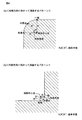
- FIG. 4 is a schematic view showing the concept of the curvature center point.
- the term “secondary battery” refers to a battery that can be repeatedly charged and discharged.
- the “secondary battery” is not excessively bound by the name, and may include, for example, “electric storage device”.
- the “plan view” in this specification is a state when an object (for example, a secondary battery) is placed and viewed from directly above its thickness (height) direction. Agree with the figure.
- a secondary battery according to an embodiment of the present invention has a structure in which an electrode assembly and an electrolyte are accommodated and enclosed in an exterior body.
- the electrode assembly includes a positive electrode, a negative electrode, and a separator disposed between the positive electrode and the negative electrode.
- the electrode assembly type is a type having a planar laminated structure in which the electrode assembly includes a plurality of unit electrode units including a positive electrode, a negative electrode, and a separator.
- a spacer is provided in the exterior body in order to prevent electronic contact between the positive and negative electrodes and the exterior body.
- the positive electrode is electronically connected to the positive electrode external terminal via the positive electrode current collecting lead.
- the external terminal for positive electrode is fixed to the exterior body by a seal portion, and the seal portion prevents electrolyte leakage.
- the negative electrode is electronically connected to the negative electrode external terminal via the negative electrode current collecting lead.
- the external terminal for negative electrode is fixed to the exterior body by a seal portion, and the seal portion prevents electrolyte leakage.
- the positive electrode is composed of at least a positive electrode material layer and a positive electrode current collector, and the positive electrode material layer is provided on at least one surface of the positive electrode current collector.
- the positive electrode material layer contains a positive electrode active material as an electrode active material.
- the negative electrode is composed of at least a negative electrode material layer and a negative electrode current collector, and the negative electrode material layer is provided on at least one surface of the negative electrode current collector.
- the negative electrode material layer contains a negative electrode active material as an electrode active material.
- the positive electrode active material included in the positive electrode material layer and the negative electrode active material included in the negative electrode material layer are materials directly involved in the transfer of electrons in the secondary battery, and are the main materials of the positive and negative electrodes that are responsible for charge / discharge, that is, the battery reaction. is there. More specifically, ions are brought into the electrolyte due to the “positive electrode active material included in the positive electrode material layer” and the “negative electrode active material included in the negative electrode material layer”, and the ions are interposed between the positive electrode and the negative electrode. Then, the electrons are transferred and the electrons are delivered and charged and discharged.
- the positive electrode material layer and the negative electrode material layer are particularly preferably layers capable of occluding and releasing lithium ions.
- the secondary battery according to this embodiment corresponds to a so-called “lithium ion battery”.
- the positive electrode active material of the positive electrode material layer is made of, for example, a granular material, and a binder (also referred to as a “binder”) is included in the positive electrode material layer for sufficient contact between the particles and shape retention. preferable. Furthermore, a conductive additive may be included in the positive electrode material layer in order to facilitate the transmission of electrons that promote the battery reaction.
- the negative electrode active material of the negative electrode material layer is made of, for example, a granular material, and it is preferable that a binder is included for sufficient contact and shape retention between the particles, facilitating the transfer of electrons that promote the battery reaction. Therefore, a conductive additive may be included in the negative electrode material layer.
- the positive electrode material layer and the negative electrode material layer can also be referred to as “positive electrode composite material layer” and “negative electrode composite material layer”, respectively.
- the positive electrode active material is preferably a material that contributes to occlusion and release of lithium ions.
- the positive electrode active material is preferably, for example, a lithium-containing composite oxide.
- the positive electrode active material is preferably a lithium transition metal composite oxide containing lithium and at least one transition metal selected from the group consisting of cobalt, nickel, manganese, and iron. That is, such a lithium transition metal composite oxide is preferably included as the positive electrode active material in the positive electrode material layer of the secondary battery.
- the positive electrode active material may be lithium cobaltate, lithium nickelate, lithium manganate, lithium iron phosphate, or a part of those transition metals replaced with another metal.
- the positive electrode active material contained in the positive electrode material layer is lithium cobalt oxide.
- the binder that can be included in the positive electrode material layer is not particularly limited, but includes polyvinylidene fluoride, vinylidene fluoride-hexafluoropropylene copolymer, vinylidene fluoride-tetrafluoroethylene copolymer, and Mention may be made of at least one selected from the group consisting of polytetrafluoroethylene and the like.
- the conductive additive that can be contained in the positive electrode material layer is not particularly limited, but carbon black such as thermal black, furnace black, channel black, ketjen black, and acetylene black, graphite, carbon nanotube, and vapor phase growth.
- the binder of the positive electrode material layer is polyvinylidene fluoride
- the conductive additive of the positive electrode material layer is carbon black.
- the binder and conductive additive of the positive electrode material layer are a combination of polyvinylidene fluoride and carbon black.
- the negative electrode active material is preferably a material that contributes to occlusion and release of lithium ions. From this point of view, the negative electrode active material is preferably, for example, various carbon materials, oxides, or lithium alloys.
- Examples of various carbon materials of the negative electrode active material include graphite (natural graphite, artificial graphite), hard carbon, soft carbon, diamond-like carbon, and the like.
- graphite is preferable in that it has high electron conductivity and excellent adhesion to the negative electrode current collector.
- Examples of the oxide of the negative electrode active material include at least one selected from the group consisting of silicon oxide, tin oxide, indium oxide, zinc oxide, lithium oxide, and the like.
- the lithium alloy of the negative electrode active material may be any metal that can be alloyed with lithium.
- Al, Si, Pb, Sn, In, Bi, Ag, Ba, Ca, Hg, Pd, Pt, Te, Zn It may be a binary, ternary or higher alloy of a metal such as La and lithium.
- a binary, ternary or higher alloy of a metal such as La and lithium.
- Such an oxide is preferably amorphous in its structural form. This is because deterioration due to non-uniformity such as crystal grain boundaries or defects is less likely to be caused.
- the negative electrode active material of the negative electrode material layer is artificial graphite.
- the binder that can be included in the negative electrode material layer is not particularly limited, but is at least one selected from the group consisting of styrene butadiene rubber, polyacrylic acid, polyvinylidene fluoride, polyimide resin, and polyamideimide resin. Can be mentioned.
- the binder contained in the negative electrode material layer is styrene butadiene rubber.
- the conductive aid that can be included in the negative electrode material layer is not particularly limited, but carbon black such as thermal black, furnace black, channel black, ketjen black, and acetylene black, graphite, carbon nanotube, and vapor phase growth.
- Examples thereof include at least one selected from carbon fibers such as carbon fibers, metal powders such as copper, nickel, aluminum and silver, and polyphenylene derivatives.
- the component resulting from the thickener component for example, carboxymethylcellulose used at the time of battery manufacture may be contained in the negative electrode material layer.
- the negative electrode active material and the binder in the negative electrode material layer are a combination of artificial graphite and styrene butadiene rubber.
- the positive electrode current collector and the negative electrode current collector used for the positive electrode and the negative electrode are members that contribute to collecting and supplying electrons generated in the active material due to the battery reaction.
- a current collector may be a sheet-like metal member and may have a porous or perforated form.
- the current collector may be a metal foil, a punching metal, a net or an expanded metal.
- the positive electrode current collector used for the positive electrode is preferably made of a metal foil containing at least one selected from the group consisting of aluminum, stainless steel, nickel and the like, and may be, for example, an aluminum foil.
- the negative electrode current collector used for the negative electrode is preferably made of a metal foil containing at least one selected from the group consisting of copper, stainless steel, nickel and the like, and may be, for example, a copper foil.
- the separator is a member provided from the viewpoint of preventing short circuit due to contact between the positive and negative electrodes and holding the electrolyte.
- the separator can be said to be a member that allows ions to pass while preventing electronic contact between the positive electrode and the negative electrode.
- the separator is a porous or microporous insulating member and has a film form due to its small thickness.
- a polyolefin microporous film may be used as the separator.
- the microporous film used as the separator may include, for example, only polyethylene (PE) or only polyethylene (PP) as the polyolefin.
- the separator may be a laminate composed of “a microporous membrane made of PE” and “a microporous membrane made of PP”.
- the surface of the separator may be covered with an inorganic particle coat layer and / or an adhesive layer.
- the surface of the separator may have adhesiveness.
- Electrolyte helps the movement of metal ions released from the electrodes (positive and negative electrodes).
- the electrolyte may be a “non-aqueous” electrolyte, such as an organic electrolyte and an organic solvent, or may be a “aqueous” electrolyte containing water.
- the secondary battery of the present invention is preferably a non-aqueous electrolyte secondary battery in which an electrolyte containing a “non-aqueous” solvent and a solute is used as an electrolyte.
- the electrolyte may have a form such as liquid or gel (in the present specification, “liquid” non-aqueous electrolyte is also referred to as “non-aqueous electrolyte solution”).
- a solvent containing at least carbonate is preferable.
- Such carbonates may be cyclic carbonates and / or chain carbonates.
- examples of the cyclic carbonates include at least one selected from the group consisting of propylene carbonate (PC), ethylene carbonate (EC), butylene carbonate (BC), and vinylene carbonate (VC). be able to.
- examples of the chain carbonates include at least one selected from the group consisting of dimethyl carbonate (DMC), diethyl carbonate (DEC), ethyl methyl carbonate (EMC), and dipropyl carbonate (DPC).
- non-aqueous electrolyte for example, a mixture of ethylene carbonate and diethyl carbonate.
- a Li salt such as LiPF 6 or LiBF 4 is preferably used as a specific nonaqueous electrolyte solute.
- the exterior body is usually a conductive hard case and consists of a main body and a lid.
- a main-body part consists of the bottom part and side part which comprise the bottom face of the said exterior body.
- the main body and the lid are sealed after the electrode assembly, the electrolyte, the current collecting lead, and the external terminal are accommodated.
- the sealing method is not particularly limited, and examples thereof include a laser irradiation method.
- a material constituting the main body part and the lid part any material capable of constituting a hard case type exterior body in the field of secondary batteries can be used.
- Such a material may be any material that can achieve electron transfer, and examples thereof include conductive materials such as aluminum, nickel, iron, copper, and stainless steel.
- the dimensions of the main body and the lid are mainly determined according to the dimensions of the electrode assembly.
- the dimensions are such that the electrode assembly is prevented from moving (displacement) within the exterior body. It is preferable to have. By preventing the movement of the electrode assembly, the electrode assembly is prevented from being destroyed, and the safety of the secondary battery is improved.
- the exterior body may be a flexible case such as a pouch made of a laminate film as long as it has conductivity.
- any spacer used in the field of secondary batteries can be used as the spacer.
- the material constituting the spacer is not particularly limited, and examples thereof include various insulating polymers such as polyolefin (polyethylene, polypyropylene), polyester (polyethylene terephthalate, polybutylene terephthalate), and acrylic polymer.
- the spacer is not particularly limited, but may have a film or non-woven fabric form.
- any current collecting lead used in the field of secondary batteries can be used.
- a current collecting lead may be made of a material that can achieve electron movement, and is made of a conductive material such as aluminum, nickel, iron, copper, and stainless steel.
- the positive electrode current collector lead is preferably composed of aluminum, and the negative electrode current collector lead is preferably composed of nickel.
- the form of the positive electrode current collector lead and the negative electrode current collector lead is not particularly limited, and may be, for example, a wire or a plate.
- the secondary battery according to an embodiment of the present invention is characterized by the arrangement and form of the positive electrode and the negative electrode of the electrode assembly that is a component thereof.
- the electrode assembly includes a separator disposed between the positive electrode and the negative electrode in addition to the positive electrode and the negative electrode.
- the positive electrode and the negative electrode are spotted. It is stated in advance that.
- the positive electrode 10 has a curved surface 12 on a part of its contour surface 11 in plan view. Specifically, the curved surface 12 is formed at the corner portion 13 of the positive electrode 10.
- the negative electrode 20 has a curved surface 22 in a part of its contour surface 21 in plan view. Specifically, the curved surface 22 is formed at the corner portion 23 of the negative electrode 20.
- the curved surface 12 of the positive electrode 10 and the curved surface 22 of the negative electrode 20 are both formed so as to bend outward in a plan view, and the curved surface 12 of the positive electrode 10 and the curved surface of the negative electrode 20 are formed. 22 are arranged adjacent to each other.
- the negative electrode 20 is disposed so as to protrude from the positive electrode 10 so that a gap G is formed between the positive electrode 10 and the negative electrode 20 in plan view.
- the “gap” here refers to a portion between the top portion 12a of the curved surface 12 of the positive electrode 10 and the top portion 22a of the curved surface 22 of the negative electrode 20 in a plan view as shown in FIG.
- the “gap length” refers to the length of a perpendicular line passing through the top 12a of the curved surface 12 of the positive electrode 10 and the top 22a of the curved surface 22 of the negative electrode 20 in plan view.
- the positive electrode 10 ′ has a curved surface 12 ′ in a part of the contour surface 11 ′ in plan view. Specifically, the curved surface 12 ′ is formed at the corner portion 13 ′ of the positive electrode 10 ′.
- the negative electrode 20 ′ has a curved surface 22 ′ as a part of its contour surface 21 ′ in plan view. Specifically, the curved surface 22 ′ is formed at the corner portion 23 ′ of the negative electrode 20 ′. As shown in FIG.
- the curved surface 12 ′ of the positive electrode 10 ′ and the curved surface 22 ′ of the negative electrode 20 ′ are both formed so as to curve inward, and the curved surface 12 ′ and the negative electrode 20 of the positive electrode 10 ′ are formed.
- the 'curved surfaces 22' are arranged adjacent to each other.
- the negative electrode 20 ′ is arranged so as to protrude from the positive electrode 10 ′ so that a gap G ′ is formed between the positive electrode 10 ′ and the negative electrode 20 ′ in a plan view.
- the bending angle ⁇ of the curved surface 22 ′ of the negative electrode 20 ′ curved toward the “inner direction” is preferably 45 ° or more and 135 ° or less, more preferably 60 ° or more and 120 °, with the bending center point C as a base point. ° or less.
- the “curvature center point” means one end of a curved surface curved inward, the other end of the curved surface curved inward, and one end of the curved surface curved inward. And a point that is equidistant from the middle point of the other end.
- the positive electrode 10 ′′ has a curved surface 12 ′′ on a part of its contour surface 11 ′′ in plan view.
- the negative electrode 20 ′′ has a curved surface 22 ′ ′ at a part of its contour surface 21 ′′ in plan view.
- both the curved surface 12 ′′ of the positive electrode 10 ′ ′ and the curved surface 22 ′′ of the negative electrode 20 ′′ are formed so as to curve outward, and the curved surface of the positive electrode 10 ′′. 12 ′′ and the curved surface 22 ′′ of the negative electrode 20 ′ ′ are arranged adjacent to each other.
- the negative electrode 20 '' is disposed so as to protrude from the positive electrode 10 '' so that a gap G '' is formed between the positive electrode 10 '' and the negative electrode 20 '' in plan view.
- the curvature angle ⁇ of the curved surface of the negative electrode curved toward the “outer” direction is the curvature center point. It is preferably 45 ° or more and 135 ° or less, more preferably 60 ° or more and 120 ° or less with C as a base point.
- the “curvature center point” here refers to one end of a curved surface curved outward, the other end of the curved surface curved outward, and one end of the curved surface curved outward. And a point that is equidistant from the middle point of the other end. Specifically, as shown in FIG.
- the “curvature center point” is a distance R between one end of the curved surface curved in the outward direction and an intermediate point of the curved surface curved in the outward direction. Both the distance R ′ and the distance R ′′ with the other end of the curved surface curved in the outward direction are the same. Specifically, as shown in FIG. 4A, the “curvature center point” is a distance R between one end of the curved surface curved outward and the middle of the curved surface curved outward. Both the distance R ′ to the point and the distance R ′′ to the other end of the curved surface curved in the outward direction are the same.
- the curvature angle ⁇ of the curved surface of the negative electrode curved toward the “inside” direction is the curvature center point C. Is preferably from 45 ° to 135 °, more preferably from 60 ° to 120 °.
- the “curvature center point” means one end of a curved surface curved inward, the other end of the curved surface curved inward, and one end of the curved surface curved inward. And a point that is equidistant from the middle point of the other end. Specifically, as shown in FIG.
- the “curvature center point” is a distance R between one end of the curved surface curved in the inner direction and the middle of the curved surface curved in the inner direction. Both the distance R ′ to the point and the distance R ′′ to the other end of the curved surface curved in the inward direction are the same.
- the inventors of the present invention divided the absolute value
- curvature radius means a length equidistant from one end of the curved surface, the other end of the curved surface, and an intermediate point between one end and the other end of the curved surface, as shown in FIG. Point to.
- / G becomes zero is set to “100%
- the inventors of the present application have a relatively high capacity when
- the curvature radius R 1 is preferably 3.0 mm or more and 500 mm or less. When the capacity becomes relatively high, the energy density of the secondary battery can be increased due to this.
- the length of the gap G is as small as possible so that the electrode (positive electrode / negative electrode) and the separator are displaced when an impact is applied from the outside, and the positive electrode and the negative electrode are short-circuited. From the viewpoint of suppressing facilitation, it is preferably 0.5 mm or more and 2.0 mm or less.
- the exterior body has an exterior body curved surface adjacent to the curved surface of the negative electrode in a part of the contour surface in plan view.
- the radius of curvature R 3 of the exterior body curved surface, the electrode assembly in the outer body From the viewpoint of enclosing a solid, it is preferable that the curvature radius R 1 of the curved surface of the negative electrode be larger.
- the radius of curvature R 3 of the exterior body curved surface it is preferred to be smaller than the radius of curvature R 1 of the curved surface of the negative electrode with a view to enclosing the electrode assembly in the outer body.
- Example 1 (G: 0.5 mm, R 1 : 3.0 mm, when the curved surface 12 of the positive electrode 10 and the curved surface 22 of the negative electrode 20 are curved outward in the corner portion (see FIG. 1)) Assuming that the capacity when
- Example 2 (G: 1.0 mm, R 1 : 20.0 mm, when the curved surface 12 ′ of the positive electrode 10 ′ and the curved surface 22 ′ of the negative electrode 20 ′ are curved inward (see FIG. 2)) Assuming that the capacity when
- Example 3 (G: 2.0 mm, R 1 : 10.0 mm, when the curved surface 12 ′′ of the positive electrode 10 ′′ and the curved surface 22 ′′ of the negative electrode 20 ′′ are curved outward (see FIG. 3) ))
- the results are shown in Table 3.
- Example 4 (G: 1.5 mm, R 1 : 150.0 mm, when the curved surface 12 ′′ of the positive electrode 10 ′′ and the curved surface 22 ′′ of the negative electrode 20 ′′ are curved outward (see FIG. 3) ))
- the results are shown in Table 4.
- the secondary battery according to an embodiment of the present invention can be used in various fields where power storage is assumed.
- the secondary battery according to an embodiment of the present invention particularly the non-aqueous electrolyte secondary battery, is merely an example, and the electric / information / communication field (for example, a mobile phone, a smart phone, a notebook) Mobile devices such as personal computers and digital cameras), home / small industrial applications (eg, power tools, golf carts, home / care / industrial robots), large industrial applications (eg, forklifts, elevators, bay ports) Crane field), transportation system field (for example, hybrid vehicle, electric vehicle, bus, train, electric assist bicycle, electric motorcycle, etc.), power system application (for example, various power generation, road conditioner, smart grid, general home installation) Field), as well as space and deep sea applications (eg space probes) It can be used in the field), such as diving research vessel.
- the electric / information / communication field for example, a mobile phone, a smart phone, a notebook
- Mobile devices such
Landscapes
- Chemical & Material Sciences (AREA)
- Engineering & Computer Science (AREA)
- Chemical Kinetics & Catalysis (AREA)
- Electrochemistry (AREA)
- General Chemical & Material Sciences (AREA)
- Materials Engineering (AREA)
- Manufacturing & Machinery (AREA)
- Secondary Cells (AREA)
- Battery Electrode And Active Subsutance (AREA)
- Sealing Battery Cases Or Jackets (AREA)
Abstract
本発明では、正極10、負極20および正極10と負極20との間に配置されたセパレータを含む電極組立体と、電解質とが外装体に収容された二次電池であって、正極10および負極20はそれぞれ、平面視において輪郭面11、21の一部に相互に隣接する湾曲面12、22を有し、かつ、負極20は、平面視において正極10と負極20との間にギャップGが形成されるように正極10よりも突出して配置されており、および負極20の湾曲面22の曲率半径R1と正極10の湾曲面12の曲率半径R2との差の絶対値|R1-R2|をギャップGで除した値(|R1-R2|/G)が0.50以上1.10以下であり、曲率半径は、湾曲面の一端、湾曲面の他端、および湾曲面における一端と他端の中間点のいずれからも等距離にある長さを指すことを特徴とする、二次電池が供される。
Description
本発明は、二次電池に関する。
従前より充放電が繰り返し可能な二次電池が様々な用途に用いられている。例えば、二次電池は、スマートフォン、ノートパソコン等の電子機器の電源として用いられている。
二次電池は、電極組立体と電解質とが外装体に収容および封入された構造を有している。電極組立体は、正極、負極、および正極と負極との間に配置されたセパレータを含んでいる。電極組立体のタイプとしては、電極組立体が正極、負極およびセパレータを含む単位電極ユニットが複数積層された平面積層構造を有するタイプが存在する。また、正極および負極はそれぞれ、平面視において輪郭面の一部に相互に隣接する湾曲面を有するものが存在する。この場合、負極は、平面視において正極と負極との間にギャップが形成されるように正極よりも突出して配置されている。
しかしながら、平面視における正極と負極との間のギャップが相対的に大きいと負極として使用されない部分が増えてしまい、その結果として二次電池のエネルギー密度が低下するおそれがある。
本発明は、エネルギー密度低下の抑止が可能な二次電池を提供することを目的とする。
上記目的を達成するために、本発明では、
正極、負極および正極と負極との間に配置されたセパレータを含む電極組立体と、電解質とが外装体に収容された二次電池であって、
正極および負極はそれぞれ、平面視において輪郭面の一部に相互に隣接する湾曲面を有し、かつ、負極は、平面視において正極と負極との間にギャップGが形成されるように正極よりも突出して配置されており、および
負極の湾曲面の曲率半径R1と正極の湾曲面の曲率半径R2との差の絶対値|R1-R2|をギャップGで除した値(|R1-R2|/G)が0.50以上1.10以下であり、曲率半径は、湾曲面の一端、湾曲面の他端、および湾曲面における一端と他端の中間点のいずれからも等距離にある長さを指すことを特徴とする、二次電池が提供される。
正極、負極および正極と負極との間に配置されたセパレータを含む電極組立体と、電解質とが外装体に収容された二次電池であって、
正極および負極はそれぞれ、平面視において輪郭面の一部に相互に隣接する湾曲面を有し、かつ、負極は、平面視において正極と負極との間にギャップGが形成されるように正極よりも突出して配置されており、および
負極の湾曲面の曲率半径R1と正極の湾曲面の曲率半径R2との差の絶対値|R1-R2|をギャップGで除した値(|R1-R2|/G)が0.50以上1.10以下であり、曲率半径は、湾曲面の一端、湾曲面の他端、および湾曲面における一端と他端の中間点のいずれからも等距離にある長さを指すことを特徴とする、二次電池が提供される。
本発明によれば、エネルギー密度低下の抑止が可能である。そのため、本発明によれば、二次電池の機能を好適に発揮することが可能である。
以下、本発明の一実施形態に係る二次電池について説明する。本明細書でいう「二次電池」という用語は充電・放電の繰り返しが可能な電池のことを指す。「二次電池」は、その名称に過度に拘泥されるものではなく、例えば、「蓄電デバイス」なども包含し得る。又、本明細書でいう「平面視」とは、対象物(例えば、二次電池)を載置してその厚み(高さ)方向の真上から見たときの状態のことであり、平面図と同意である。まず、本発明の一実施形態に係る二次電池の「特徴部分」について説明する前に、本発明の一実施形態に係る二次電池の基本的構成について説明しておく。
[本発明の二次電池の構成]
本発明の一実施形態に係る二次電池は、電極組立体と電解質とが外装体に収容および封入された構造を有している。電極組立体は、正極、負極、および正極と負極との間に配置されたセパレータを含んでいる。本発明の一実施形態では、電極組立体のタイプは、電極組立体が正極、負極およびセパレータを含む単位電極ユニットが複数積層された平面積層構造を有するタイプとなっている。また、外装体内には、正極および負極と外装体との間の電子的接触を防止するために、スペーサーが設けられている。正極は、正極用集電リードを介して、正極用外部端子に電子的に連結されている。正極用外部端子はシール部により外装体に固定され、当該シール部は電解質の液漏れを防止する。同様に、負極は、負極用集電リードを介して負極用外部端子に電子的に連結されている。負極用外部端子はシール部により外装体に固定され、シール部が電解質の液漏れを防止する。
本発明の一実施形態に係る二次電池は、電極組立体と電解質とが外装体に収容および封入された構造を有している。電極組立体は、正極、負極、および正極と負極との間に配置されたセパレータを含んでいる。本発明の一実施形態では、電極組立体のタイプは、電極組立体が正極、負極およびセパレータを含む単位電極ユニットが複数積層された平面積層構造を有するタイプとなっている。また、外装体内には、正極および負極と外装体との間の電子的接触を防止するために、スペーサーが設けられている。正極は、正極用集電リードを介して、正極用外部端子に電子的に連結されている。正極用外部端子はシール部により外装体に固定され、当該シール部は電解質の液漏れを防止する。同様に、負極は、負極用集電リードを介して負極用外部端子に電子的に連結されている。負極用外部端子はシール部により外装体に固定され、シール部が電解質の液漏れを防止する。
正極は少なくとも正極材層および正極集電体から構成されており、正極集電体の少なくとも片面に正極材層が設けられている。正極材層には電極活物質として正極活物質が含まれている。負極は少なくとも負極材層および負極集電体から構成されており、負極集電体の少なくとも片面に負極材層が設けられている。負極材層には電極活物質として負極活物質が含まれている。
正極材層に含まれる正極活物質および負極材層に含まれる負極活物質は、二次電池において電子の受け渡しに直接関与する物質であり、充放電、すなわち電池反応を担う正負極の主物質である。より具体的には、「正極材層に含まれる正極活物質」および「負極材層に含まれる負極活物質」に起因して電解質にイオンがもたらされ、かかるイオンが正極と負極との間で移動して電子の受け渡しが行われて充放電がなされる。正極材層および負極材層は特にリチウムイオンを吸蔵放出可能な層であることが好ましい。つまり、電解質を介してリチウムイオンが正極と負極との間で移動して電池の充放電が行われる二次電池が好ましい。充放電にリチウムイオンが関与する場合、本実施態様に係る二次電池は、いわゆる“リチウムイオン電池”に相当する。
正極材層の正極活物質は例えば粒状体から成るところ、粒子同士の十分な接触と形状保持のためにバインダー(“結着材”とも称される)が正極材層に含まれていることが好ましい。更には、電池反応を推進する電子の伝達を円滑にするために導電助剤が正極材層に含まれていてよい。同様に、負極材層の負極活物質は例えば粒状体から成るところ、粒子同士の十分な接触と形状保持のためにバインダーが含まれることが好ましく、電池反応を推進する電子の伝達を円滑にするために導電助剤が負極材層に含まれていてよい。このように、複数の成分が含有されて成る形態ゆえ、正極材層および負極材層はそれぞれ“正極合材層”および“負極合材層”などと称すこともできる。
正極活物質は、リチウムイオンの吸蔵放出に資する物質であることが好ましい。かかる観点でいえば、正極活物質は例えばリチウム含有複合酸化物であることが好ましい。より具体的には、正極活物質は、リチウムと、コバルト、ニッケル、マンガンおよび鉄から成る群から選択される少なくとも1種の遷移金属とを含むリチウム遷移金属複合酸化物であることが好ましい。つまり、二次電池の正極材層においては、そのようなリチウム遷移金属複合酸化物が正極活物質として好ましくは含まれている。例えば、正極活物質はコバルト酸リチウム、ニッケル酸リチウム、マンガン酸リチウム、リン酸鉄リチウム、または、それらの遷移金属の一部を別の金属で置き換えたものであってよい。このような正極活物質は、単独種として含まれてよいものの、二種以上が組み合わされて含まれていてもよい。より好適な態様では正極材層に含まれる正極活物質がコバルト酸リチウムとなっている。
正極材層に含まれる得るバインダーとしては、特に制限されるわけではないが、ポリフッ化ビリニデン、ビリニデンフルオライド-ヘキサフルオロプロピレン共重合体、ビリニデンフルオライド-テトラフルオロチレン共重合体およびポリテトラフルオロチレンなどから成る群から選択される少なくとも1種を挙げることができる。正極材層に含まれ得る導電助剤としては、特に制限されるわけではないが、サーマルブラック、ファーネスブラック、チャンネルブラック、ケッチェンブラックおよびアセチレンブラック等のカーボンブラック、黒鉛、カーボンナノチューブおよび気相成長炭素繊維等の炭素繊維、銅、ニッケル、アルミニウムおよび銀等の金属粉末、ならびに、ポリフェニレン誘導体などから選択される少なくとも1種を挙げることができる。より好適な態様では正極材層のバインダーはポリフッ化ビニリデンであり、また、別のより好適な態様では正極材層の導電助剤はカーボンブラックである。さらに好適な態様では、正極材層のバインダーおよび導電助剤が、ポリフッ化ビニリデンとカーボンブラックとの組合せとなっている。
負極活物質は、リチウムイオンの吸蔵放出に資する物質であることが好ましい。かかる観点でいえば、負極活物質は例えば各種の炭素材料、酸化物、または、リチウム合金などであることが好ましい。
負極活物質の各種の炭素材料としては、黒鉛(天然黒鉛、人造黒鉛)、ハードカーボン、ソフトカーボン、ダイヤモンド状炭素などを挙げることができる。特に、黒鉛は電子伝導性が高く、負極集電体との接着性が優れる点などで好ましい。負極活物質の酸化物としては、酸化シリコン、酸化スズ、酸化インジウム、酸化亜鉛および酸化リチウムなどから成る群から選択される少なくとも1種を挙げることができる。負極活物質のリチウム合金は、リチウムと合金形成され得る金属であればよく、例えば、Al、Si、Pb、Sn、In、Bi、Ag、Ba、Ca、Hg、Pd、Pt、Te、Zn、Laなどの金属とリチウムとの2元、3元またはそれ以上の合金であってよい。このような酸化物は、その構造形態としてアモルファスとなっていることが好ましい。結晶粒界または欠陥といった不均一性に起因する劣化が引き起こされにくくなるからである。より好適な態様では負極材層の負極活物質が人造黒鉛となっている。
負極材層に含まれる得るバインダーとしては、特に制限されるわけではないが、スチレンブタジエンゴム、ポリアクリル酸、ポリフッ化ビニリデン、ポリイミド系樹脂およびポリアミドイミド系樹脂から成る群から選択される少なくとも1種を挙げることができる。より好適な実施態様では負極材層に含まれるバインダーはスチレンブタジエンゴムとなっている。負極材層に含まれる得る導電助剤としては、特に制限されるわけではないが、サーマルブラック、ファーネスブラック、チャンネルブラック、ケッチェンブラックおよびアセチレンブラック等のカーボンブラック、黒鉛、カーボンナノチューブおよび気相成長炭素繊維等の炭素繊維、銅、ニッケル、アルミニウムおよび銀等の金属粉末、ならびに、ポリフェニレン誘導体などから選択される少なくとも1種を挙げることができる。なお、負極材層には、電池製造時に使用された増粘剤成分(例えばカルボキシルメチルセルロース)に起因する成分が含まれていてもよい。
さらに好適な態様では、負極材層における負極活物質およびバインダーが人造黒鉛とスチレンブタジエンゴムとの組合せとなっている。
正極および負極に用いられる正極集電体および負極集電体は電池反応に起因して活物質で発生した電子を集めたり供給したりするのに資する部材である。このような集電体は、シート状の金属部材であってよく、多孔または穿孔の形態を有していてよい。例えば、集電体は金属箔、パンチングメタル、網またはエキスパンドメタル等であってよい。正極に用いられる正極集電体は、アルミニウム、ステンレスおよびニッケル等から成る群から選択される少なくとも1種を含んだ金属箔から成るものが好ましく、例えばアルミニウム箔であってよい。一方、負極に用いられる負極集電体は、銅、ステンレスおよびニッケル等から成る群から選択される少なくとも1種を含んだ金属箔から成るものが好ましく、例えば銅箔であってよい。
セパレータは、正負極の接触による短絡防止および電解質保持などの観点から設けられる部材である。換言すれば、セパレータは、正極と負極との間の電子的接触を防止しつつイオンを通過させる部材であるといえる。好ましくは、セパレータは多孔性または微多孔性の絶縁性部材であり、その小さい厚みに起因して膜形態を有している。あくまでも例示にすぎないが、ポリオレフィン製の微多孔膜がセパレータとして用いられてよい。この点、セパレータとして用いられる微多孔膜は、例えば、ポリオレフィンとしてポリエチレン(PE)のみ又はポリエチレン(PP)のみを含んだものであってよい。更にいえば、セパレータは、“PE製の微多孔膜”と“PP製の微多孔膜”とから構成される積層体であってもよい。セパレータの表面は無機粒子コート層および/または接着層等により覆われていてもよい。セパレータの表面は接着性を有していてもよい。
電解質は電極(正極・負極)から放出された金属イオンの移動を助力する。電解質は有機電解質および有機溶媒などの“非水系”の電解質であっても、または水を含む“水系”の電解質であってもよい。本発明の二次電池は、電解質として“非水系”の溶媒と、溶質とを含む電解質が用いられた非水電解質二次電池が好ましい。電解質は液体状またはゲル状などの形態を有し得る(なお、本明細書において“液体状”の非水電解質は「非水電解質液」とも称される)。
具体的な非水電解質の溶媒としては、少なくともカーボネートを含んで成るものが好ましい。かかるカーボネートは、環状カーボネート類および/または鎖状カーボネート類であってもよい。特に制限されるわけではないが、環状カーボネート類としては、プロピレンカーボネート(PC)、エチレンカーボネート(EC)、ブチレンカーボネート(BC)およびビニレンカーボネート(VC)から成る群から選択される少なくとも1種を挙げることができる。鎖状カーボネート類としては、ジメチルカーボネート(DMC)、ジエチルカーボネート(DEC)、エチルメチルカーボネート(EMC)およびジプロピルカーボネート(DPC)から成る群から選択される少なくも1種を挙げることができる。本発明の1つの好適な実施態様では、非水電解質として環状カーボネート類と鎖状カーボネート類との組合せが用いられ、例えばエチレンカーボネートとジエチルカーボネートとの混合物が用いられる。また、具体的な非水電解質の溶質としては、好ましくは例えばLiPF6、LiBF4等のLi塩が用いられる。
外装体は通常、導電性ハードケースであり、本体部および蓋部からなっている。本体部は当該外装体の底面を構成する底部および側面部から成る。本体部と蓋部とは、電極組立体、電解質、集電リードおよび外部端子の収容後に密封される。密封方法としては、特に限定されるものではなく、例えばレーザー照射法等が挙げられる。本体部および蓋部を構成する材料としては、二次電池の分野でハードケース型外装体を構成し得るあらゆる材料が使用可能である。そのような材料は電子の移動が達成され得る材料であればよく、例えばアルミニウム、ニッケル、鉄、銅、ステンレスなどの導電性材料が挙げられる。本体部および蓋部の寸法は、主として電極組立体の寸法に応じて決定され、例えば電極組立体を収容したとき、外装体内での電極組立体の移動(ズレ)が防止される程度の寸法を有することが好ましい。電極組立体の移動を防止することにより、電極組立体の破壊が防止され、二次電池の安全性が向上する。なお、外装体は、導電性を有する限り、ラミネートフィルムからなるパウチ等のフレキシブルケースであってもよい。
スペーサーとしては、二次電池の分野で使用されているあらゆるスペーサーが使用可能である。スペーサーを構成する材料としては、特に限定されるものではないが、ポリオレフィン(ポリエチレン、ポリピロピレン)、ポリエステル(ポリエチレンテレフタレート、ポリブチレンテレフタレート)、アクリルポリマー等種々の絶縁性ポリマーが挙げられる。また、スペーサーは、特に限定されるものではないが、フィルム、不織布の形態を有していてよい。
正極用集電リードおよび負極用集電リードとしては、二次電池の分野で使用されているあらゆる集電リードが使用可能である。そのような集電リードは、電子の移動が達成され得る材料から構成されればよく、例えばアルミニウム、ニッケル、鉄、銅、ステンレスなどの導電性材料から構成される。正極用集電リードはアルミニウムから構成されることが好ましく、負極用集電リードはニッケルから構成されることが好ましい。正極用集電リードおよび負極用集電リードの形態は特に限定されず、例えば、線又はプレート状であってよい。
[本発明の二次電池の特徴部分]
本発明の一実施形態に係る二次電池は、その構成要素である電極組立体の正極と負極の配置および形態に特徴を有している。以下、その特徴について説明する。なお、上述のように電極組立体は、正極および負極に加えて、正極と負極との間に配置されるセパレータも含んでいるが、下記内容および図面は正極と負極とにスポットを当てたものとすることを予め述べておく。
本発明の一実施形態に係る二次電池は、その構成要素である電極組立体の正極と負極の配置および形態に特徴を有している。以下、その特徴について説明する。なお、上述のように電極組立体は、正極および負極に加えて、正極と負極との間に配置されるセパレータも含んでいるが、下記内容および図面は正極と負極とにスポットを当てたものとすることを予め述べておく。
(第1実施形態)
本発明の第1実施形態に係る二次電池では、図1に示すように正極10は平面視においてその輪郭面11の一部に湾曲面12を有している。具体的には、かかる湾曲面12は正極10のコーナー部13に形成されている。また、負極20は平面視においてその輪郭面21の一部に湾曲面22を有している。具体的には、かかる湾曲面22は負極20のコーナー部23に形成されている。図1に示すように、正極10の湾曲面12と負極20の湾曲面22は平面視においていずれも外側方向に向かって湾曲するように形成され、正極10の湾曲面12と負極20の湾曲面22は相互に隣接するように配置されている。また、負極20は、平面視において正極10と負極20との間にギャップGが形成されるように正極10より突出するように配置されている。なお、ここでいう「ギャップ」とは、図1に示すように平面視において正極10の湾曲面12の頂部12aと負極20の湾曲面22の頂部22aとの間の部分を指し、後述の「ギャップ長さ」とは、平面視において正極10の湾曲面12の頂部12aと負極20の湾曲面22の頂部22aとを通る垂線の長さを指す。
本発明の第1実施形態に係る二次電池では、図1に示すように正極10は平面視においてその輪郭面11の一部に湾曲面12を有している。具体的には、かかる湾曲面12は正極10のコーナー部13に形成されている。また、負極20は平面視においてその輪郭面21の一部に湾曲面22を有している。具体的には、かかる湾曲面22は負極20のコーナー部23に形成されている。図1に示すように、正極10の湾曲面12と負極20の湾曲面22は平面視においていずれも外側方向に向かって湾曲するように形成され、正極10の湾曲面12と負極20の湾曲面22は相互に隣接するように配置されている。また、負極20は、平面視において正極10と負極20との間にギャップGが形成されるように正極10より突出するように配置されている。なお、ここでいう「ギャップ」とは、図1に示すように平面視において正極10の湾曲面12の頂部12aと負極20の湾曲面22の頂部22aとの間の部分を指し、後述の「ギャップ長さ」とは、平面視において正極10の湾曲面12の頂部12aと負極20の湾曲面22の頂部22aとを通る垂線の長さを指す。
(第2実施形態)
本発明の第2実施形態に係る二次電池では、図2に示すように正極10’は平面視においてその輪郭面11’の一部に湾曲面12’を有している。具体的には、かかる湾曲面12’は正極10’のコーナー部13’に形成されている。また、負極20’は平面視においてその輪郭面21’の一部に湾曲面22’を有している。具体的には、かかる湾曲面22’は負極20’のコーナー部23’に形成されている。図2に示すように、正極10’の湾曲面12’と負極20’の湾曲面22’はいずれも内側方向に向かって湾曲するように形成され、正極10’の湾曲面12’と負極20’の湾曲面22’は相互に隣接するように配置されている。また、負極20’は、平面視において正極10’と負極20’との間にギャップG’が形成されるように正極10’より突出するように配置されている。この場合、「内側方向」に向かって湾曲した負極20’の湾曲面22’の湾曲角度θは湾曲中心点Cを基点として好ましくは45°以上135°以下であり、より好ましくは60°以上120°以下である。なお、ここでいう「湾曲中心点」とは、内側方向に向かって湾曲した湾曲面の一端、内側方向に向かって湾曲した湾曲面の他端、および内側方向に向かって湾曲した湾曲面における一端と他端の中間点のいずれからも等距離にある点を指す。
本発明の第2実施形態に係る二次電池では、図2に示すように正極10’は平面視においてその輪郭面11’の一部に湾曲面12’を有している。具体的には、かかる湾曲面12’は正極10’のコーナー部13’に形成されている。また、負極20’は平面視においてその輪郭面21’の一部に湾曲面22’を有している。具体的には、かかる湾曲面22’は負極20’のコーナー部23’に形成されている。図2に示すように、正極10’の湾曲面12’と負極20’の湾曲面22’はいずれも内側方向に向かって湾曲するように形成され、正極10’の湾曲面12’と負極20’の湾曲面22’は相互に隣接するように配置されている。また、負極20’は、平面視において正極10’と負極20’との間にギャップG’が形成されるように正極10’より突出するように配置されている。この場合、「内側方向」に向かって湾曲した負極20’の湾曲面22’の湾曲角度θは湾曲中心点Cを基点として好ましくは45°以上135°以下であり、より好ましくは60°以上120°以下である。なお、ここでいう「湾曲中心点」とは、内側方向に向かって湾曲した湾曲面の一端、内側方向に向かって湾曲した湾曲面の他端、および内側方向に向かって湾曲した湾曲面における一端と他端の中間点のいずれからも等距離にある点を指す。
(第3実施形態)
本発明の第3実施形態に係る二次電池では、図3に示すように正極10’’は平面視においてその輪郭面11’’の一部に湾曲面12’’を有している。また、負極20’’は平面視においてその輪郭面21’’の一部に湾曲面22’ ’を有している。図3に示すように、正極10’ ’の湾曲面12’’と負極20’’の湾曲面22’’はいずれも外側方向に向かって湾曲するように形成され、正極10’’の湾曲面12’’と負極20’ ’の湾曲面22’’は相互に隣接するように配置されている。また、負極20’’は、平面視において正極10’’と負極20’’との間にギャップG’’が形成されるように正極10’’より突出するように配置されている。
本発明の第3実施形態に係る二次電池では、図3に示すように正極10’’は平面視においてその輪郭面11’’の一部に湾曲面12’’を有している。また、負極20’’は平面視においてその輪郭面21’’の一部に湾曲面22’ ’を有している。図3に示すように、正極10’ ’の湾曲面12’’と負極20’’の湾曲面22’’はいずれも外側方向に向かって湾曲するように形成され、正極10’’の湾曲面12’’と負極20’ ’の湾曲面22’’は相互に隣接するように配置されている。また、負極20’’は、平面視において正極10’’と負極20’’との間にギャップG’’が形成されるように正極10’’より突出するように配置されている。
上述の第1および第3実施形態のように、湾曲面が「外側」方向に向かって湾曲する場合において、「外側」方向に向かって湾曲した負極の湾曲面の湾曲角度θは、湾曲中心点Cを基点として好ましくは45°以上135°以下であり、より好ましくは60°以上120°以下である。なお、ここでいう「湾曲中心点」とは、外側方向に向かって湾曲した湾曲面の一端、外側方向に向かって湾曲した湾曲面の他端、および外側方向に向かって湾曲した湾曲面における一端と他端の中間点のいずれからも等距離にある点を指す。具体的には、図4に示すように、「湾曲中心点」とは、外側方向に向かって湾曲した湾曲面の一端との距離R、外側方向に向かって湾曲した湾曲面の中間点との距離R’、および外側方向に向かって湾曲した湾曲面の他端との距離R’’のいずれもが等しくなる点を指す。具体的には、図4(a)に示すように、「湾曲中心点」とは、外側方向に向かって湾曲した湾曲面の一端との距離R、外側方向に向かって湾曲した湾曲面の中間点との距離R’、および外側方向に向かって湾曲した湾曲面の他端との距離R’’のいずれもが等しくなる点を指す。
一方、上述の第2実施形態のように、湾曲面が「内側」方向に向かって湾曲する場合において、「内側」方向に向かって湾曲した負極の湾曲面の湾曲角度θは、湾曲中心点Cを基点として好ましくは45°以上135°以下であり、より好ましくは60°以上120°以下である。なお、ここでいう「湾曲中心点」とは、内側方向に向かって湾曲した湾曲面の一端、内側方向に向かって湾曲した湾曲面の他端、および内側方向に向かって湾曲した湾曲面における一端と他端の中間点のいずれからも等距離にある点を指す。具体的には、図4(b)に示すように、「湾曲中心点」とは、内側方向に向かって湾曲した湾曲面の一端との距離R、内側方向に向かって湾曲した湾曲面の中間点との距離R’、および内側方向に向かって湾曲した湾曲面の他端との距離R’’のいずれもが等しくなる点を指す。
ここで、本願発明者らは、上記第1~第3の実施形態にて平面視における正極(10、10’、10’’)と負極(20、20’、20’’)との間のギャップ(G、G’、G’’)が相対的に大きい場合に生じる「二次電池のエネルギー密度の低下」を防止するために鋭意検討した。
その結果、本願発明者らは、負極の湾曲面の曲率半径R1と正極の湾曲面の曲率半径R2との差の絶対値|R1-R2|をギャップGで除した値(以下、|R1-R2|/Gと記載する。)が所定範囲であると、好適に「二次電池の高エネルギー密度化」および「正極と負極との短絡防止」が可能となることを見出した。なお、ここでいう「曲率半径」とは、図4に示すように湾曲面の一端、湾曲面の他端、および湾曲面における一端と他端の中間点のいずれからも等距離にある長さを指す。
具体的には、負極の湾曲面の曲率半径R1と正極の湾曲面の曲率半径R2とが等しく、それにより|R1-R2|/Gがゼロとなる場合の容量を「100%」とすると、本願発明者らは下記の実施例1~4からも分かるように|R1-R2|/Gが0.50以上1.10以下の範囲にあると容量が相対的に高くなることを見出した。なお、この場合の曲率半径R1は3.0mm以上500mm以下であることが好ましい。当該容量が相対的に高くなると、それに起因して二次電池のエネルギー密度を高くすることができる。
また、ギャップGの長さは、負極として使用されない部分を可能な限り少なくしつつ、外部から衝撃が加わった際に電極(正極・負極)およびセパレータがずれ、それにより正極と負極とが短絡し易くなることを抑制する観点から0.5mm以上2.0mm以下であることが好ましい。
また、図示しないが、本発明の一実施形態に係る二次電池では、外装体は、平面視において輪郭面の一部に負極の湾曲面に隣接する外装体湾曲面を有している。一実施形態では、外装体の湾曲面と、正極の湾曲面および負極の湾曲面とが外側方向に向かって湾曲している場合、外装体湾曲面の曲率半径R3は、外装体内に電極組立体を封入するという観点から負極の湾曲面の曲率半径R1よりも大きくなることが好ましい。その一方で、別の実施形態では、外装体の湾曲面と、正極の湾曲面および負極の湾曲面とが内側方向に向かって湾曲している場合、外装体湾曲面の曲率半径R3は、外装体内に電極組立体を封入するという観点から負極の湾曲面の曲率半径R1よりも小さくなることが好ましい。
実施例1
(G:0.5mm、R1:3.0mm、正極10の湾曲面12と負極20の湾曲面22がコーナー部において外側方向に向かって湾曲している場合(図1参照))
|R1-R2|/Gがゼロとなる場合の容量を「100%」として、正極10の湾曲面12の曲率半径R2値を変化させた場合の容量割合をシミュレーション解析した。その結果を表1に示す。
(G:0.5mm、R1:3.0mm、正極10の湾曲面12と負極20の湾曲面22がコーナー部において外側方向に向かって湾曲している場合(図1参照))
|R1-R2|/Gがゼロとなる場合の容量を「100%」として、正極10の湾曲面12の曲率半径R2値を変化させた場合の容量割合をシミュレーション解析した。その結果を表1に示す。
(表1)

表1からも分かるように、|R1-R2|/Gが0.50以上1.10以下の範囲にあると、|R1-R2|/Gがゼロとなる場合の容量と比べて、容量が相対的に高くなることを見出した。
実施例2
(G:1.0mm、R1:20.0mm、正極10’の湾曲面12’と負極20’の湾曲面22’が内側方向に向かって湾曲している場合(図2参照))
|R1-R2|/Gがゼロとなる場合の容量を「100%」として、正極10’の湾曲面12’の曲率半径R2値を変化させた場合の容量割合をシミュレーション解析した。その結果を表2に示す。
(G:1.0mm、R1:20.0mm、正極10’の湾曲面12’と負極20’の湾曲面22’が内側方向に向かって湾曲している場合(図2参照))
|R1-R2|/Gがゼロとなる場合の容量を「100%」として、正極10’の湾曲面12’の曲率半径R2値を変化させた場合の容量割合をシミュレーション解析した。その結果を表2に示す。
(表2)
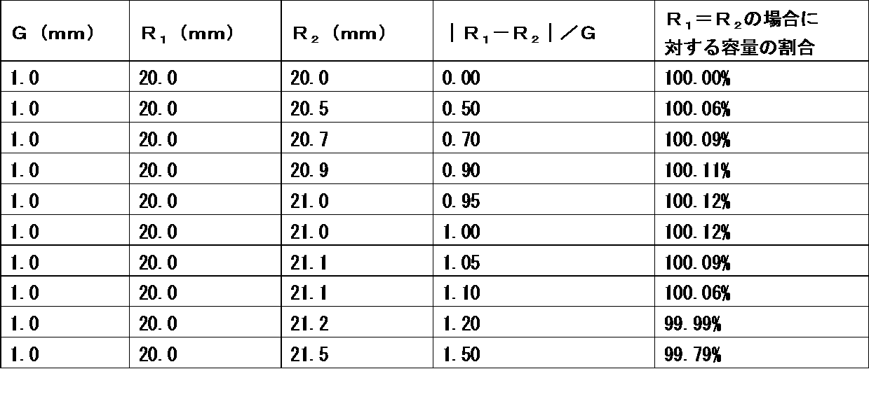
表2からも分かるように、|R1-R2|/Gが0.50以上1.10以下の範囲にあると、|R1-R2|/Gがゼロとなる場合の容量と比べて、容量が相対的に高くなることを見出した。
実施例3
(G:2.0mm、R1:10.0mm、正極10’’の湾曲面12’’と負極20’’の湾曲面22’’が外側方向に向かって湾曲している場合(図3参照))
|R1-R2|/Gがゼロとなる場合の容量を「100%」として、正極10’’の湾曲面12’’の曲率半径R2値を変化させた場合の容量割合をシミュレーション解析した。その結果を表3に示す。
(G:2.0mm、R1:10.0mm、正極10’’の湾曲面12’’と負極20’’の湾曲面22’’が外側方向に向かって湾曲している場合(図3参照))
|R1-R2|/Gがゼロとなる場合の容量を「100%」として、正極10’’の湾曲面12’’の曲率半径R2値を変化させた場合の容量割合をシミュレーション解析した。その結果を表3に示す。
(表3)
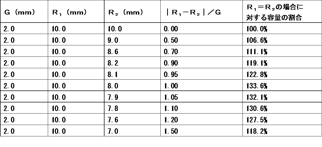
表3からも分かるように、|R1-R2|/Gが0.50以上1.10以下の範囲にあると、|R1-R2|/Gがゼロとなる場合の容量と比べて、容量が相対的に高くなることを見出した。
実施例4
(G:1.5mm、R1:150.0mm、正極10’’の湾曲面12’’と負極20’’の湾曲面22’’が外側方向に向かって湾曲している場合(図3参照))
|R1-R2|/Gがゼロとなる場合の容量を「100%」として、正極10’’の湾曲面12’’の曲率半径R2値を変化させた場合の容量割合をシミュレーション解析した。その結果を表4に示す。
(G:1.5mm、R1:150.0mm、正極10’’の湾曲面12’’と負極20’’の湾曲面22’’が外側方向に向かって湾曲している場合(図3参照))
|R1-R2|/Gがゼロとなる場合の容量を「100%」として、正極10’’の湾曲面12’’の曲率半径R2値を変化させた場合の容量割合をシミュレーション解析した。その結果を表4に示す。
(表4)
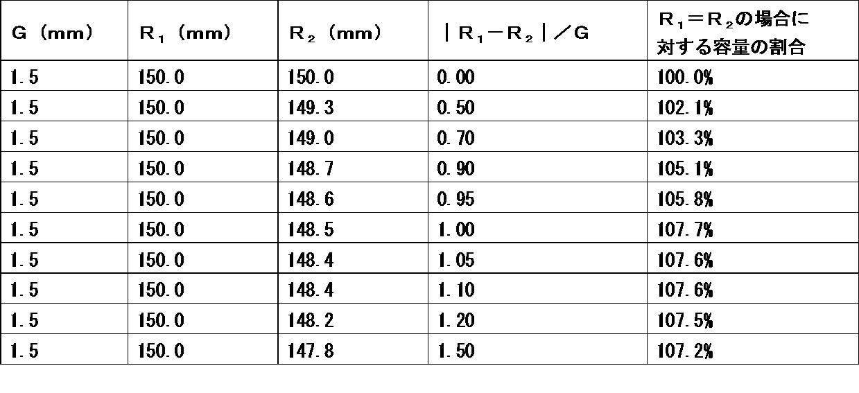
表4からも分かるように、|R1-R2|/Gが0.50以上1.10以下の範囲にあると、|R1-R2|/Gがゼロとなる場合の容量と比べて、容量が相対的に高くなることを見出した。
本発明の一実施形態に係る二次電池は、蓄電が想定される様々な分野に利用することができる。あくまでも例示にすぎないが、本発明の一実施形態に係る二次電池、特に非水電解質二次電池は、モバイル機器などが使用される電気・情報・通信分野(例えば、携帯電話、スマートフォン、ノートパソコンおよびデジタルカメラなどのモバイル機器分野)、家庭・小型産業用途(例えば、電動工具、ゴルフカート、家庭用・介護用・産業用ロボットの分野)、大型産業用途(例えば、フォークリフト、エレベーター、湾港クレーンの分野)、交通システム分野(例えば、ハイブリッド車、電気自動車、バス、電車、電動アシスト自転車、電動二輪車などの分野)、電力系統用途(例えば、各種発電、ロードコンディショナー、スマートグリッド、一般家庭設置型蓄電システムなどの分野)、ならびに、宇宙・深海用途(例えば、宇宙探査機、潜水調査船などの分野)に利用することができる。
10 正極
10’ 正極
10’’ 正極
11 正極の輪郭面
11’ 正極の輪郭面
11’’ 正極の輪郭面
12 正極の湾曲面
12’ 正極の湾曲面
12’’ 正極の湾曲面
13 正極のコーナー部
13’ 正極のコーナー部
20 負極
20’ 負極
20’ 負極
21 負極の輪郭面
21’ 負極の輪郭面
21’’ 負極の輪郭面
22 負極の湾曲面
22’ 負極の湾曲面
22’’ 負極の湾曲面
23 負極のコーナー部
23’ 負極のコーナー部
C 湾曲中心点
θ 湾曲角度
G ギャップ
10’ 正極
10’’ 正極
11 正極の輪郭面
11’ 正極の輪郭面
11’’ 正極の輪郭面
12 正極の湾曲面
12’ 正極の湾曲面
12’’ 正極の湾曲面
13 正極のコーナー部
13’ 正極のコーナー部
20 負極
20’ 負極
20’ 負極
21 負極の輪郭面
21’ 負極の輪郭面
21’’ 負極の輪郭面
22 負極の湾曲面
22’ 負極の湾曲面
22’’ 負極の湾曲面
23 負極のコーナー部
23’ 負極のコーナー部
C 湾曲中心点
θ 湾曲角度
G ギャップ
Claims (8)
- 正極、負極および該正極と該負極との間に配置されたセパレータを含む電極組立体と、電解質とが外装体に収容された二次電池であって、
前記正極および前記負極はそれぞれ、平面視において輪郭面の一部に相互に隣接する湾曲面を有し、かつ、前記負極は、平面視において前記正極と前記負極との間にギャップGが形成されるように前記正極よりも突出して配置されており、および
前記負極の前記湾曲面の曲率半径R1と前記正極の前記湾曲面の曲率半径R2との差の絶対値|R1-R2|を前記ギャップGで除した値(|R1-R2|/G)が0.50以上1.10以下であり、前記曲率半径は、前記湾曲面の一端、前記湾曲面の他端、および前記湾曲面における該一端と該他端の中間点のいずれからも等距離にある長さを指すことを特徴とする、二次電池。 - 前記電極組立体は、前記正極、前記負極および前記セパレータを含む単位電極ユニットが複数積層された平面積層構造を有することを特徴とする、請求項1に記載の二次電池。
- 前記ギャップGの長さが、0.5mm以上2.0mm以下であることを特徴とする、請求項1又は2に記載の二次電池。
- 前記曲率半径R1が3.0mm以上500mm以下であることを特徴とする、請求項1~3のいずれかに記載の二次電池。
- 前記外装体は、平面視において輪郭面の一部に前記負極の前記湾曲面に隣接する外装体湾曲面を有し、
前記外装体の湾曲面と、前記正極および前記負極の前記湾曲面とが外側方向に向かって湾曲している場合、前記外装体湾曲面の曲率半径R3が前記負極の前記湾曲面の曲率半径R1よりも大きいことを特徴とする、請求項1~4のいずれかに記載の二次電池。 - 前記外装体は、平面視において輪郭面の一部に前記負極の前記湾曲面に隣接する外装体湾曲面を有し、
前記外装体の湾曲面と、前記正極および前記負極の前記湾曲面とが内側方向に向かって湾曲している場合、前記外装体湾曲面の曲率半径R3が前記負極の前記湾曲面の曲率半径R1よりも小さいことを特徴とする、請求項1~4のいずれかに記載の二次電池。 - 前記正極および前記負極がリチウムイオンを吸蔵放出可能な電極である、請求項1~6のいずれかに記載の二次電池。
- 前記正極には、リチウムと、コバルト、ニッケル、マンガンおよび鉄から成る群から選択される少なくとも1種の遷移金属とを含むリチウム遷移金属複合酸化物が正極活物質として含まれ、
前記負極には、炭素材料が負極活物質として含まれることを特徴とする、請求項1~7のいずれかに記載の二次電池。
Priority Applications (3)
| Application Number | Priority Date | Filing Date | Title |
|---|---|---|---|
| CN201780033839.7A CN109219903B (zh) | 2016-05-31 | 2017-02-24 | 充电电池 |
| JP2018520365A JPWO2017208531A1 (ja) | 2016-05-31 | 2017-02-24 | 二次電池 |
| US16/157,335 US11342590B2 (en) | 2016-05-31 | 2018-10-11 | Secondary battery |
Applications Claiming Priority (2)
| Application Number | Priority Date | Filing Date | Title |
|---|---|---|---|
| JP2016109170 | 2016-05-31 | ||
| JP2016-109170 | 2016-05-31 |
Related Child Applications (1)
| Application Number | Title | Priority Date | Filing Date |
|---|---|---|---|
| US16/157,335 Continuation US11342590B2 (en) | 2016-05-31 | 2018-10-11 | Secondary battery |
Publications (1)
| Publication Number | Publication Date |
|---|---|
| WO2017208531A1 true WO2017208531A1 (ja) | 2017-12-07 |
Family
ID=60479281
Family Applications (1)
| Application Number | Title | Priority Date | Filing Date |
|---|---|---|---|
| PCT/JP2017/007222 Ceased WO2017208531A1 (ja) | 2016-05-31 | 2017-02-24 | 二次電池 |
Country Status (4)
| Country | Link |
|---|---|
| US (1) | US11342590B2 (ja) |
| JP (1) | JPWO2017208531A1 (ja) |
| CN (1) | CN109219903B (ja) |
| WO (1) | WO2017208531A1 (ja) |
Cited By (3)
| Publication number | Priority date | Publication date | Assignee | Title |
|---|---|---|---|---|
| JP2022094745A (ja) * | 2020-12-15 | 2022-06-27 | 株式会社豊田自動織機 | 蓄電装置 |
| CN117977072A (zh) * | 2024-02-04 | 2024-05-03 | 蜂巢能源科技股份有限公司 | 电芯壳体、电芯及电池包 |
| JP7793326B2 (ja) | 2021-09-24 | 2026-01-05 | マクセル株式会社 | 袋状のセパレータに収容された電極、積層電極体及び扁平形電池 |
Citations (5)
| Publication number | Priority date | Publication date | Assignee | Title |
|---|---|---|---|---|
| JPH0256856A (ja) * | 1988-08-20 | 1990-02-26 | Sanyo Electric Co Ltd | 電池及びその極板の製造方法 |
| JPH0982361A (ja) * | 1995-09-08 | 1997-03-28 | Sony Corp | 角形非水電解液二次電池 |
| JP2000285881A (ja) * | 1999-03-30 | 2000-10-13 | Kyocera Corp | 薄型電池およびその製造方法 |
| JP2013134881A (ja) * | 2011-12-26 | 2013-07-08 | Toyota Industries Corp | 蓄電装置および蓄電装置を搭載した車両 |
| JP2014049371A (ja) * | 2012-09-03 | 2014-03-17 | Hitachi Maxell Ltd | 扁平形非水二次電池およびその製造方法 |
Family Cites Families (5)
| Publication number | Priority date | Publication date | Assignee | Title |
|---|---|---|---|---|
| JPH11234071A (ja) * | 1998-02-16 | 1999-08-27 | Murata Mfg Co Ltd | チップ状電子部品の製造方法 |
| JP5618706B2 (ja) * | 2010-08-26 | 2014-11-05 | 日立マクセル株式会社 | 積層型電池 |
| JP2012204335A (ja) * | 2011-03-28 | 2012-10-22 | Mitsubishi Heavy Ind Ltd | 非水電解質二次電池及び非水電解質二次電池の製造方法 |
| WO2013168980A1 (ko) | 2012-05-07 | 2013-11-14 | 주식회사 엘지화학 | 비정형 구조의 전지팩 |
| EP2958177B1 (en) | 2013-03-08 | 2017-05-31 | Lg Chem, Ltd. | Electrode assembly having rounded corners |
-
2017
- 2017-02-24 JP JP2018520365A patent/JPWO2017208531A1/ja active Pending
- 2017-02-24 WO PCT/JP2017/007222 patent/WO2017208531A1/ja not_active Ceased
- 2017-02-24 CN CN201780033839.7A patent/CN109219903B/zh active Active
-
2018
- 2018-10-11 US US16/157,335 patent/US11342590B2/en active Active
Patent Citations (5)
| Publication number | Priority date | Publication date | Assignee | Title |
|---|---|---|---|---|
| JPH0256856A (ja) * | 1988-08-20 | 1990-02-26 | Sanyo Electric Co Ltd | 電池及びその極板の製造方法 |
| JPH0982361A (ja) * | 1995-09-08 | 1997-03-28 | Sony Corp | 角形非水電解液二次電池 |
| JP2000285881A (ja) * | 1999-03-30 | 2000-10-13 | Kyocera Corp | 薄型電池およびその製造方法 |
| JP2013134881A (ja) * | 2011-12-26 | 2013-07-08 | Toyota Industries Corp | 蓄電装置および蓄電装置を搭載した車両 |
| JP2014049371A (ja) * | 2012-09-03 | 2014-03-17 | Hitachi Maxell Ltd | 扁平形非水二次電池およびその製造方法 |
Cited By (4)
| Publication number | Priority date | Publication date | Assignee | Title |
|---|---|---|---|---|
| JP2022094745A (ja) * | 2020-12-15 | 2022-06-27 | 株式会社豊田自動織機 | 蓄電装置 |
| JP7585760B2 (ja) | 2020-12-15 | 2024-11-19 | 株式会社豊田自動織機 | 蓄電装置 |
| JP7793326B2 (ja) | 2021-09-24 | 2026-01-05 | マクセル株式会社 | 袋状のセパレータに収容された電極、積層電極体及び扁平形電池 |
| CN117977072A (zh) * | 2024-02-04 | 2024-05-03 | 蜂巢能源科技股份有限公司 | 电芯壳体、电芯及电池包 |
Also Published As
| Publication number | Publication date |
|---|---|
| JPWO2017208531A1 (ja) | 2018-10-04 |
| CN109219903B (zh) | 2021-08-24 |
| CN109219903A (zh) | 2019-01-15 |
| US11342590B2 (en) | 2022-05-24 |
| US20190044188A1 (en) | 2019-02-07 |
Similar Documents
| Publication | Publication Date | Title |
|---|---|---|
| US11811022B2 (en) | Secondary battery | |
| US10998600B2 (en) | Laminated secondary battery and manufacturing method of the same, and device | |
| WO2017209052A1 (ja) | 二次電池 | |
| JP6879358B2 (ja) | 二次電池 | |
| JPWO2018154989A1 (ja) | 二次電池およびその製造方法 | |
| US11342590B2 (en) | Secondary battery | |
| US20190074535A1 (en) | Secondary battery | |
| US11929467B2 (en) | Secondary battery | |
| JP2020173890A (ja) | 組電池および組電池の製造方法 | |
| US20190334210A1 (en) | Secondary battery | |
| WO2020218213A1 (ja) | 二次電池 | |
| WO2018131398A1 (ja) | 二次電池 | |
| JP7456163B2 (ja) | 二次電池 | |
| JPWO2018131346A1 (ja) | 二次電池 | |
| US12034127B2 (en) | Secondary battery | |
| JP6773133B2 (ja) | 二次電池 | |
| WO2017208683A1 (ja) | 二次電池 | |
| WO2017208534A1 (ja) | 二次電池 | |
| JP7115554B2 (ja) | 二次電池 | |
| WO2018163775A1 (ja) | 二次電池の製造方法 | |
| JPWO2018154987A1 (ja) | 二次電池およびその製造方法 | |
| WO2022009997A1 (ja) | 二次電池 | |
| WO2017208532A1 (ja) | 二次電池 | |
| JP2018206490A (ja) | 二次電池およびその製造方法 | |
| WO2018116623A1 (ja) | 二次電池および電池組合体 |
Legal Events
| Date | Code | Title | Description |
|---|---|---|---|
| ENP | Entry into the national phase |
Ref document number: 2018520365 Country of ref document: JP Kind code of ref document: A |
|
| NENP | Non-entry into the national phase |
Ref country code: DE |
|
| 121 | Ep: the epo has been informed by wipo that ep was designated in this application |
Ref document number: 17806093 Country of ref document: EP Kind code of ref document: A1 |
|
| 122 | Ep: pct application non-entry in european phase |
Ref document number: 17806093 Country of ref document: EP Kind code of ref document: A1 |