WO2017208500A1 - 吸収性物品の製造方法及び接着剤の塗布装置 - Google Patents
吸収性物品の製造方法及び接着剤の塗布装置 Download PDFInfo
- Publication number
- WO2017208500A1 WO2017208500A1 PCT/JP2017/004079 JP2017004079W WO2017208500A1 WO 2017208500 A1 WO2017208500 A1 WO 2017208500A1 JP 2017004079 W JP2017004079 W JP 2017004079W WO 2017208500 A1 WO2017208500 A1 WO 2017208500A1
- Authority
- WO
- WIPO (PCT)
- Prior art keywords
- melt adhesive
- hot melt
- application
- adhesive
- absorbent article
- Prior art date
- Legal status (The legal status is an assumption and is not a legal conclusion. Google has not performed a legal analysis and makes no representation as to the accuracy of the status listed.)
- Ceased
Links
Images



Classifications
-
- A—HUMAN NECESSITIES
- A61—MEDICAL OR VETERINARY SCIENCE; HYGIENE
- A61F—FILTERS IMPLANTABLE INTO BLOOD VESSELS; PROSTHESES; DEVICES PROVIDING PATENCY TO, OR PREVENTING COLLAPSING OF, TUBULAR STRUCTURES OF THE BODY, e.g. STENTS; ORTHOPAEDIC, NURSING OR CONTRACEPTIVE DEVICES; FOMENTATION; TREATMENT OR PROTECTION OF EYES OR EARS; BANDAGES, DRESSINGS OR ABSORBENT PADS; FIRST-AID KITS
- A61F13/00—Bandages or dressings; Absorbent pads
- A61F13/15—Absorbent pads, e.g. sanitary towels, swabs or tampons for external or internal application to the body; Supporting or fastening means therefor; Tampon applicators
- A61F13/15577—Apparatus or processes for manufacturing
-
- A—HUMAN NECESSITIES
- A61—MEDICAL OR VETERINARY SCIENCE; HYGIENE
- A61F—FILTERS IMPLANTABLE INTO BLOOD VESSELS; PROSTHESES; DEVICES PROVIDING PATENCY TO, OR PREVENTING COLLAPSING OF, TUBULAR STRUCTURES OF THE BODY, e.g. STENTS; ORTHOPAEDIC, NURSING OR CONTRACEPTIVE DEVICES; FOMENTATION; TREATMENT OR PROTECTION OF EYES OR EARS; BANDAGES, DRESSINGS OR ABSORBENT PADS; FIRST-AID KITS
- A61F13/00—Bandages or dressings; Absorbent pads
- A61F13/15—Absorbent pads, e.g. sanitary towels, swabs or tampons for external or internal application to the body; Supporting or fastening means therefor; Tampon applicators
-
- A—HUMAN NECESSITIES
- A61—MEDICAL OR VETERINARY SCIENCE; HYGIENE
- A61F—FILTERS IMPLANTABLE INTO BLOOD VESSELS; PROSTHESES; DEVICES PROVIDING PATENCY TO, OR PREVENTING COLLAPSING OF, TUBULAR STRUCTURES OF THE BODY, e.g. STENTS; ORTHOPAEDIC, NURSING OR CONTRACEPTIVE DEVICES; FOMENTATION; TREATMENT OR PROTECTION OF EYES OR EARS; BANDAGES, DRESSINGS OR ABSORBENT PADS; FIRST-AID KITS
- A61F13/00—Bandages or dressings; Absorbent pads
- A61F13/15—Absorbent pads, e.g. sanitary towels, swabs or tampons for external or internal application to the body; Supporting or fastening means therefor; Tampon applicators
- A61F13/45—Absorbent pads, e.g. sanitary towels, swabs or tampons for external or internal application to the body; Supporting or fastening means therefor; Tampon applicators characterised by the shape
- A61F13/47—Sanitary towels, incontinence pads or napkins
- A61F13/472—Sanitary towels, incontinence pads or napkins specially adapted for female use
-
- A—HUMAN NECESSITIES
- A61—MEDICAL OR VETERINARY SCIENCE; HYGIENE
- A61F—FILTERS IMPLANTABLE INTO BLOOD VESSELS; PROSTHESES; DEVICES PROVIDING PATENCY TO, OR PREVENTING COLLAPSING OF, TUBULAR STRUCTURES OF THE BODY, e.g. STENTS; ORTHOPAEDIC, NURSING OR CONTRACEPTIVE DEVICES; FOMENTATION; TREATMENT OR PROTECTION OF EYES OR EARS; BANDAGES, DRESSINGS OR ABSORBENT PADS; FIRST-AID KITS
- A61F13/00—Bandages or dressings; Absorbent pads
- A61F13/15—Absorbent pads, e.g. sanitary towels, swabs or tampons for external or internal application to the body; Supporting or fastening means therefor; Tampon applicators
- A61F13/51—Absorbent pads, e.g. sanitary towels, swabs or tampons for external or internal application to the body; Supporting or fastening means therefor; Tampon applicators characterised by the outer layers of the pads
- A61F13/515—Absorbent pads, e.g. sanitary towels, swabs or tampons for external or internal application to the body; Supporting or fastening means therefor; Tampon applicators characterised by the outer layers of the pads characterised by the interconnection of the topsheet and the backsheet
-
- B—PERFORMING OPERATIONS; TRANSPORTING
- B05—SPRAYING OR ATOMISING IN GENERAL; APPLYING FLUENT MATERIALS TO SURFACES, IN GENERAL
- B05C—APPARATUS FOR APPLYING FLUENT MATERIALS TO SURFACES, IN GENERAL
- B05C11/00—Component parts, details or accessories not specifically provided for in groups B05C1/00 - B05C9/00
- B05C11/10—Storage, supply or control of liquid or other fluent material; Recovery of excess liquid or other fluent material
-
- B—PERFORMING OPERATIONS; TRANSPORTING
- B05—SPRAYING OR ATOMISING IN GENERAL; APPLYING FLUENT MATERIALS TO SURFACES, IN GENERAL
- B05C—APPARATUS FOR APPLYING FLUENT MATERIALS TO SURFACES, IN GENERAL
- B05C5/00—Apparatus in which liquid or other fluent material is projected, poured or allowed to flow on to the surface of the work
- B05C5/001—Apparatus in which liquid or other fluent material is projected, poured or allowed to flow on to the surface of the work incorporating means for heating or cooling the liquid or other fluent material
-
- B—PERFORMING OPERATIONS; TRANSPORTING
- B05—SPRAYING OR ATOMISING IN GENERAL; APPLYING FLUENT MATERIALS TO SURFACES, IN GENERAL
- B05C—APPARATUS FOR APPLYING FLUENT MATERIALS TO SURFACES, IN GENERAL
- B05C5/00—Apparatus in which liquid or other fluent material is projected, poured or allowed to flow on to the surface of the work
- B05C5/02—Apparatus in which liquid or other fluent material is projected, poured or allowed to flow on to the surface of the work the liquid or other fluent material being discharged through an outlet orifice by pressure, e.g. from an outlet device in contact or almost in contact, with the work
-
- A—HUMAN NECESSITIES
- A61—MEDICAL OR VETERINARY SCIENCE; HYGIENE
- A61F—FILTERS IMPLANTABLE INTO BLOOD VESSELS; PROSTHESES; DEVICES PROVIDING PATENCY TO, OR PREVENTING COLLAPSING OF, TUBULAR STRUCTURES OF THE BODY, e.g. STENTS; ORTHOPAEDIC, NURSING OR CONTRACEPTIVE DEVICES; FOMENTATION; TREATMENT OR PROTECTION OF EYES OR EARS; BANDAGES, DRESSINGS OR ABSORBENT PADS; FIRST-AID KITS
- A61F13/00—Bandages or dressings; Absorbent pads
- A61F13/15—Absorbent pads, e.g. sanitary towels, swabs or tampons for external or internal application to the body; Supporting or fastening means therefor; Tampon applicators
- A61F13/15577—Apparatus or processes for manufacturing
- A61F2013/15821—Apparatus or processes for manufacturing characterized by the apparatus for manufacturing
- A61F2013/15861—Apparatus or processes for manufacturing characterized by the apparatus for manufacturing for bonding
- A61F2013/15878—Apparatus or processes for manufacturing characterized by the apparatus for manufacturing for bonding by thermal bonding
-
- A—HUMAN NECESSITIES
- A61—MEDICAL OR VETERINARY SCIENCE; HYGIENE
- A61F—FILTERS IMPLANTABLE INTO BLOOD VESSELS; PROSTHESES; DEVICES PROVIDING PATENCY TO, OR PREVENTING COLLAPSING OF, TUBULAR STRUCTURES OF THE BODY, e.g. STENTS; ORTHOPAEDIC, NURSING OR CONTRACEPTIVE DEVICES; FOMENTATION; TREATMENT OR PROTECTION OF EYES OR EARS; BANDAGES, DRESSINGS OR ABSORBENT PADS; FIRST-AID KITS
- A61F13/00—Bandages or dressings; Absorbent pads
- A61F13/15—Absorbent pads, e.g. sanitary towels, swabs or tampons for external or internal application to the body; Supporting or fastening means therefor; Tampon applicators
- A61F13/15577—Apparatus or processes for manufacturing
- A61F2013/15821—Apparatus or processes for manufacturing characterized by the apparatus for manufacturing
- A61F2013/15861—Apparatus or processes for manufacturing characterized by the apparatus for manufacturing for bonding
- A61F2013/1591—Apparatus or processes for manufacturing characterized by the apparatus for manufacturing for bonding via adhesive
Definitions
- the present invention relates to a method for manufacturing an absorbent article and an adhesive application apparatus.
- Absorbent articles such as sanitary napkins and disposable diapers are known. Many of the materials constituting the absorbent article are bonded to other materials with a hot melt adhesive. That is, a hot melt adhesive is used at a plurality of locations in one absorbent article. Therefore, in the manufacture of absorbent articles, there are relatively many hot melt adhesive application processes, and accordingly, the production line has a large number of hot melt adhesive application devices and occupies a wide area. Can do.
- an intermittent application apparatus of Patent Document 1 is an apparatus that intermittently applies a coating agent to the surface of a coating object that is transported in the transport direction, and includes one coating liquid tank for one coating nozzle, and one type of adhesive. Can be applied.
- the absorbent article there are a plurality of types of absorbent articles in which the hot melt adhesives for the material are different from each other, for example, because the types of materials are different from each other.
- a sanitary napkin a plurality of types of hot melt adhesives for a breathable sheet and a non-breathable sheet are different from each other due to different types of back sheet such as a breathable sheet and a non-breathable sheet.
- back sheet such as a breathable sheet and a non-breathable sheet.
- sanitary napkins There are sanitary napkins.
- Such a plurality of types of absorbent articles may be manufactured on a single production line with different time zones. That is, after continuously producing one type of absorbent article in a certain time zone on the production line, continuously producing another type of absorbent article in another time zone on the same production line, This is the case. In that case, it is necessary to change the hot melt adhesive depending on the type of the absorbent article to be manufactured.
- next coating device is the same type of device as the previous coating device, it is necessary to make adjustments because the state of the detailed configuration, for example, the state of the valves and nozzles, is not the same, and also in this respect It takes time and effort.
- An object of the present invention is to produce a plurality of types of absorbent articles on a single production line, to produce different types of absorbent articles, and to switch hot melt adhesives according to the type of the absorbent article.
- Absorbent article manufacturing method and adhesive applicator capable of maintaining the functions and characteristics of absorbent articles by suppressing the mixing of impurities into hot melt adhesive while suppressing the space, time and labor of It is to provide.
- the manufacturing method of the absorbent article of the present invention is as follows. (1) A plurality of materials constituting an absorbent article are bonded with a hot melt adhesive, and a plurality of types of absorbent articles having different hot melt adhesives corresponding to at least one of the plurality of materials are bonded together. A method of manufacturing an absorbent article that can be manufactured on a single production line including an agent coating device, wherein the coating device includes a first receiving port, a second receiving port, and a sending port, A switching unit that switches the communication receiving port from one of the first receiving port and the second receiving port to the other; and a first hot melt adhesive that supplies the first hot melt adhesive to the first receiving port.
- the supply unit, the switching unit, and the coating unit are heated, the first receiving port of the switching unit is communicated with the delivery port, and the first hot melt adhesive is fed by the coating unit.
- a second application step in which the second receiving port of the switching unit communicates with the delivery port and the second hot melt adhesive is applied to the second material by the application unit; Article manufacturing method.
- the manufacturing method of this absorbent article can change a hot-melt-adhesive easily only by switching a switching part, when the kind of the absorbent article manufactured by the said structure is changed. At this time, in this manufacturing method, it is only necessary to add a set of supply parts substantially, and it is not necessary to arrange another coating device in parallel, so that space is saved. In this manufacturing method, since the application part is shared by two types of hot melt adhesives, it is necessary to make almost adjustments compared to the case where the application device itself is switched or an additional application device is used. Eliminates time and effort. Furthermore, in this manufacturing method, since switching of equipment is substantially unnecessary, time and labor can be reduced as compared with the case where the coating apparatus itself is switched.
- the hot melt adhesive when the hot melt adhesive is switched, the application part / switching part shared by the two types of hot melt adhesives remains substantially heated, so that the previous hot melt adhesive is applied to the application part / switching part. Curing and adhesion can be reduced.
- the hot-melt adhesive after switching it is possible to avoid a situation in which the hot-melt adhesive before curing and adhering is gradually peeled off and mixed as impurities into the hot-melt adhesive after switching.
- the first hot melt adhesive and the second hot melt adhesive have melting points different from each other.
- the first hot melt adhesive has the first melting point.
- the supply unit, the switching unit, and the coating unit are heated at a temperature higher than the melting point based on the melting point of the first hot melt adhesive, and in the second coating step, the second supply
- the part, the switching part, and the application part are heated at a temperature higher than the melting point based on the melting point of the second hot melt adhesive. There may be.
- the hot melt adhesive is cured and adhered by a pipe or valve that is moving, even if the melting point of the hot melt adhesive is different due to the difference in the hot melt adhesive. This can prevent the contamination of the hot melt adhesive and maintain the function and characteristics of the absorbent article.
- various hot melt adhesives having different melting points can be used for application, it is possible to select a hot melt adhesive suitable for maintaining the function and characteristics of the absorbent article. The degree of freedom in selecting the second material can be increased.
- the second supply unit is heated before the end of the first application step, (1) or (2
- the manufacturing method of the absorbent article as described in) may be sufficient.
- the second hot melt adhesive can be sufficiently melted and applied immediately after the end of the first application step.
- the first hot melt adhesive can be immediately switched to the second hot melt adhesive, and thus the second application process can be immediately performed. That is, the switching time of the hot melt adhesive can be suppressed.
- the manufacturing method of the absorbent article of this invention is (4)
- the apparatus of the said production line is attached to the front side of the wall surface,
- the said 1st supply part, the said 2nd supply part, and the said switch part are the back sides of the said wall surface.
- the distance between the coating portion on the front side of the wall surface and the first supply portion, the second supply portion, and the switching portion is close, and their adjustment is easy. Time and labor in switching the melt adhesive can be reduced. Further, since the back side of the wall surface is used as the installation space for the first supply unit, the second supply unit, and the switching unit, the front side is space-saving.
- the manufacturing method of the absorbent article of this invention is (5) each of the said 1st supply part and the said 2nd supply part adhere
- An application supply pipe, and the application section includes an application nozzle and an adhesive delivery pipe connecting the application nozzle and the switching section, and the switching section, the adhesive delivery pipe, and the application nozzle.
- the volume of the flow path through which the first hot-melt adhesive and the second hot-melt adhesive in common flow in the first and second hot-melt adhesives in the switching unit and the adhesive supply pipe is 2 is smaller than the volume of the flow path through which one of the hot-melt adhesives circulates exclusively, and the second application step includes the first part in the switching unit, the adhesive delivery pipe, and the application nozzle.
- a hot melt adhesive; (1) to (4) including a replacement step of extruding with the second hot melt adhesive supplied from the adhesive supply pipe of the supply portion and replacing the second hot melt adhesive The manufacturing method of the absorbent article as described in any one of these may be sufficient.
- the amount of the second hot melt adhesive to be pushed out can be reduced and the first hot melt adhesive can be removed from the shared portion by the above configuration in the replacement step.
- the time required for the replacement process can be shortened, the time and labor for switching the hot melt adhesive can be reduced, the hot melt adhesive can be switched, and impurities in the second hot melt adhesive can be reduced. Mixing can be suppressed.
- each of the first application step and the second application step includes an intermittent application step of intermittently applying the hot melt adhesive to the material, Any of the above (1) to (5), in which the intermittent application control of the first application process and the intermittent application process of the second application process are performed by the application apparatus.
- the manufacturing method of the absorbent article as described in any one of the above may be sufficient.
- the first application step and the second application step share the same structure of the device that performs intermittent application, that is, the application unit, and control that performs intermittent application, that is, the application unit. Therefore, the adjustment of the coating device at the time of switching the hot melt adhesive can be made easier than the case of using a device for intermittent coating and a separate coating device with different control.
- the manufacturing method of the absorbent article of this invention is (7)
- the said application part contains the application nozzle for contact-type application
- the second hot-melt adhesive is contact-coated on the second material with the application nozzle for contact application,
- the manufacturing method of the absorbent article as described in any one of (1) to (6) above may be used.
- the hot melt adhesive is applied to the material with the application nozzle for contact type application, the remaining adhesion of the hot melt adhesive to the nozzle that may occur with the application nozzle for non-contact type application Can reduce the effects of Thereby, the hot melt adhesive can be easily switched, and time and labor can be suppressed.
- the adhesive applicator of the present invention is as follows. (8) A first receiving port, a second receiving port, and a sending / receiving port are provided, and the receiving port communicating with the sending / receiving port is switched from one of the first receiving port and the second receiving port to the other. A switching unit, a first supply unit that supplies the first hot melt adhesive to the first receiving port, and a second hot melt adhesive different from the first hot melt adhesive. A second supply unit that supplies the material to the receiving port, and an application unit that is connected to the delivery port and applies the first hot melt adhesive or the second hot melt adhesive delivered from the delivery port to the material. And an adhesive applicator.
- the hot melt adhesive can be easily changed by simply switching the switching unit when the type of article to be manufactured is changed.
- this coating apparatus it is only necessary to add a set of supply parts substantially, and it is not necessary to arrange another coating apparatus in parallel, so that space is saved.
- the coating part is shared by two types of hot melt adhesives, it is necessary to make almost adjustments compared to the case where the coating apparatus itself is switched or an additional coating apparatus is used. Eliminates time and effort.
- switching of equipment is substantially unnecessary, time and labor can be reduced as compared with the case of switching the coating apparatus itself.
- the hot melt adhesive when the hot melt adhesive is switched, the application part / switching part shared by the two types of hot melt adhesives remains substantially heated, so that the previous hot melt adhesive is applied to the application part / switching part. Curing and adhesion can be reduced.
- the hot-melt adhesive after switching it is possible to avoid a situation in which the hot-melt adhesive before curing and adhering is gradually peeled off and mixed as impurities into the hot-melt adhesive after switching.
- the function and characteristics of the article due to impurities are reduced, defective products are produced, and the production yield is reduced.
- this coating apparatus when one of the two types of hot melt adhesives is applied to a material, by using a coating apparatus that is partially used in common, It is possible to maintain the function and characteristics of the article by suppressing the mixing of impurities into the hot melt adhesive while suppressing time and labor.
- a space for switching the hot melt adhesive according to the type of the absorbent article Provided is a method for manufacturing an absorbent article and an adhesive application device capable of maintaining the functions and characteristics of the absorbent article by suppressing the mixing of impurities into the hot melt adhesive while suppressing time and labor. It becomes possible.
- the configuration of the absorbent article 1 will be described.
- 1 and 2 are a plan view and an exploded perspective view of the absorbent article 1 in a developed state.
- the absorbent article 1 has an absorbent article body 1A and a packaging sheet 1B, and the absorbent article body 1A is detachably fixed to the substantially rectangular packaging sheet 1B.
- the absorbent article main body 1A has a longitudinal direction L, a width direction W, and a thickness direction H orthogonal to each other, a central axis CL extending in the longitudinal direction L through the center of the width direction W, and a pair of flap portions 2b, 2b. It has a central axis CW extending in the width direction W through the center in the longitudinal direction L (described later).
- the upper side and the lower side are the front and rear of the absorbent article main body 1A, respectively. Since the longitudinal direction L and the width direction W of the absorbent article body 1A coincide with the longitudinal direction and the width direction of the packaging sheet 1B, the longitudinal direction L and the width direction W are used in common for the absorbent article body 1A and the packaging sheet 1B. . Moreover, in this specification, seeing the absorbent article 1 or the absorbent article main body 1A in a state of being expanded and flattened in the thickness direction from the upper surface side is simply referred to as “plan view”.
- “Skin side” and “non-skin side” mean that the wearer of the absorbent article main body 1A wears the absorbent article main body 1A and is relatively closer to and far from the wearer's skin surface in the thickness direction H. Means each side.
- a direction toward the central axis CL and a direction away from the central axis CL are defined as directions on the inner side and the outer side in the width direction W, respectively.
- the direction toward the central axis CW and the direction away from the central axis CW are defined as the inner and outer directions of the longitudinal direction L.
- the absorbent article main body 1A (sanitary napkin) includes a main body portion 2a extending in the longitudinal direction L, and a pair of flap portions 2b and 2b extending to both sides in the width direction W at a substantially central portion in the longitudinal direction L.
- the pressing part 2E is provided around the excretion opening contact area of the main body part 2a.
- Absorbent article body 1A includes at least a liquid-permeable surface sheet 2 located on the skin side of the wearer, a liquid-impermeable back sheet 3 located on the non-skin side of the wearer, and the surface sheet 2 and the back surface. It is comprised with the liquid absorptive and liquid holding
- Examples of the surface sheet 2 include any liquid-permeable sheet such as a liquid-permeable nonwoven fabric or woven fabric, a synthetic resin film in which liquid-permeable holes are formed, and a composite sheet thereof.
- Examples of the back sheet 3 include liquid-impermeable sheets such as liquid-impermeable nonwoven fabrics and synthetic resin films, composite sheets thereof, and SMS nonwoven fabrics.
- the back sheet 3 may have air permeability or moisture permeability in addition to liquid impermeability in order to reduce stuffiness during wearing.
- An exterior sheet 9 that reinforces the back sheet 3 and improves the touch may be laminated on the non-skin side of the back sheet 3. As the exterior sheet 9, the same material as the back sheet 3 can be used.
- absorbent body 4 includes an upper layer core wrap 4U on the skin side, a lower layer core wrap 4L on the non-skin side, and an absorbent core 4A located between upper layer core wrap 4U and lower layer core wrap 4L.
- absorbent body 4 or the absorbent core 4A include pulp fibers, synthetic fibers, and absorbent polymers.
- the upper layer core wrap 4U and the lower layer core wrap 4L include a nonwoven fabric and a tissue.
- the absorbent article body 1A is not limited to this configuration, and a known configuration generally used in the absorbent article 1 can be used.
- the absorber 4 and the top sheet 2 are joined to each other by an adhesive 45 having a predetermined pattern (not shown), and the absorber 4 and the back sheet 3 are joined to each other by an adhesive 46 having a predetermined pattern (not shown). .
- the top sheet 2 and the back sheet 3 are bonded to each other at their peripheral portions by adhesives 45 and 46 having a predetermined pattern (not shown).
- the absorbent core 4A and the upper layer core wrap 4U are bonded to each other by an adhesive 43 having a predetermined pattern (not shown), and the absorbent core 4A and the lower layer core wrap 4L are bonded to each other by an adhesive 44 having a predetermined pattern (not shown).
- the upper layer core wrap 4U and the lower layer core wrap 4L are joined to each other by adhesives 43 and 44 having a predetermined pattern (not shown) at their peripheral portions.
- the main body 2a of the absorbent article main body 1A includes a fixing portion 42 on the non-skin side of the back sheet 3.
- the fixing portion 42 is extended in the longitudinal direction L with a predetermined width in the width direction W.
- Each flap portion 2b of the absorbent article main body 1A includes another fixing portion 41 on the non-skin side of the back sheet 3.
- the other fixing portion 41 is extended in the longitudinal direction L with a predetermined width in the width direction W.
- a sticky adhesive is used as the fixing portions 41 and 42.
- the absorbent article main body 1A is fixed to the packaging sheet 1B via the fixing portions 41 and 42.
- the packaging sheet 1B has release sheets 31 and 32 at the portions in contact with the fixing portions 41 and 42, respectively, and the absorbent article body 1A is fixed to the packaging sheet 1B so as to be peelable.
- the release sheets 31 and 32 and the packaging sheet 1B are bonded to each other with an adhesive 47 having a predetermined pattern (not shown).
- the fixing parts 41 and 42 are not limited to the shape, and a known shape and number generally used in the absorbent article 1 can be used.
- a known adhesive material generally used in the absorbent article 1 such as a thermoplastic resin adhesive is used, but at least one is a hot melt adhesive. used.
- the material of each hot-melt-adhesive can be used, for example, polyolefin type (PE type, EVA type, EEA type, APP type, APO type) and synthetic rubber type (SIS type, SBSS type, etc.).
- additives examples: tackifiers, plasticizers, antioxidants, etc.
- the material (type) of the hot melt adhesive is appropriately changed depending on the desired characteristics and compatibility with the applied material.
- Such hot melt adhesives have different melting points depending on differences in materials and additives.
- the absorbent article main body 1A and the packaging sheet 1B are folded at the positions of a plurality of folding lines FLT1, FLT2 extending in parallel to the longitudinal direction L in a state where the absorbent article main body 1A is fixed to the packaging sheet 1B.
- the folds are folded at a plurality of fold lines FLV1, FLV2, FLV2 ′ extending in parallel with W.
- An adhesive lead tape 35 is affixed to the front end of the packaging sheet 1B in the longitudinal direction L.
- Examples of the material for the packaging sheet 1B include known materials generally used for packaging the absorbent article body 1A, such as resin films, paper, and nonwoven fabrics.
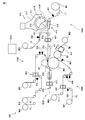
- FIG. 3 is a schematic diagram showing the configuration of the manufacturing apparatus 300 for the absorbent article 1.
- the manufacturing apparatus 300 includes a first forming unit 300A, a second forming unit 300B, a third forming unit 300C, a fourth forming unit 300D, and a control device 300X exemplified by a computer.
- the manufacturing method of the absorbent article using the manufacturing apparatus 300 includes a first forming process performed by the first forming unit 300A, a second forming process performed by the second forming unit 300B, and a third forming process.
- the control device 300X controls the operation of the manufacturing device 300.
- the rotary drum 111 of the fiber stacking device 110 is rotated, and the fiber material supplied from the material supplier 113 is deposited in the groove communicating with the negative pressure chamber 111N of the pattern plate 112, The laminated fiber AB is formed.
- the pattern plate 112 reaches the positive pressure chamber 111P together with the stacked fiber body AB, the stacked fiber body AB is detached from the pattern plate 112.
- a continuous sheet-like upper tissue sheet UT is supplied from the roll WR1 to the transport belt 115.
- a hot melt adhesive (corresponding to the adhesive 43) is applied to one surface of the upper tissue sheet UT by a coating device 301.
- the fiber stack AB is pressed onto one surface of the upper tissue sheet UT on the transport belt 115.
- the first semi-finished product P1 is formed.
- the first semi-finished product P1 is sucked by the suction device 116 and is transported by the transport belt 115.
- a continuous sheet-like lower layer tissue sheet LT is supplied to the conveyance belt 115 from the roll WR2.
- a hot melt adhesive (corresponding to the adhesive 44) is applied to one surface of the lower layer tissue sheet LT by the application device 302.
- One surface of the lower tissue sheet LT is pressed against the first semi-finished product P1 on the transport belt 115.
- the second semi-finished product P2 is formed.
- the second semi-finished product P ⁇ b> 2 is pressed by the pressing device 120 and is cut into the shape of the absorber 4 by the cutting device 130. Thereby, the 3rd semi-finished product P3 which is the absorber 4 is formed.
- the third semi-finished product P3 is delivered to the transport roll 141.
- the continuous sheet-like surface sheet TS is supplied from the roll WR3 to the transport belt 140.
- a hot melt adhesive (corresponding to the adhesive 45) is applied to one surface of the top sheet TS by the coating device 303.
- the third semi-finished product P3 supplied from the transport roll 141 is pressed against one surface of the top sheet TS.
- the fourth semi-finished product P4 is formed.
- the fourth semi-finished product P4 is squeezed by the squeezing device 150 to form a fifth semi-finished product P5.
- the fifth semi-finished product P5 is delivered to the transport roll 160.
- the continuous sheet-like back sheet BS is supplied from the roll WR4 to the transport roll 161.
- a hot melt adhesive (adhesive 46) is applied to one surface of the back sheet BS by the application device 304.
- the back sheet BS supplied from the transport roll 161 is pressed onto the one surface of the fifth semi-finished product P5 on the transport roll 160. Thereby, a sixth semi-finished product P6 is formed.
- the sixth semi-finished product P6 is delivered to the transport roll 170.
- the continuous sheet-like release sheet CT is supplied from the roll WR5 to the back surface fixing portion forming apparatus 171.
- a hot melt adhesive (corresponding to the fixing portion 42) is applied to one surface of the release sheet CT by the coating device 305.
- the release sheet CT is cut into a predetermined shape by the back surface fixing part forming device 171.
- the release sheet CT becomes the release sheet 32
- the hot melt adhesive becomes the fixing portion 42.
- fixed part 42 is pressed on the 6th semi-finished product P6.
- a seventh semi-finished product P7 is formed.
- the seventh semi-finished product P7 is heated at the peripheral portion by the peripheral sealing device 180 and is edged with a heat seal. Thereby, the eighth semi-finished product P8 is formed.
- the eighth semi-finished product P8 is transported to the transport roll 190.
- the continuous sheet-like release sheet FT is supplied from the roll WR6 to the flap fixing part forming device 191.
- a hot melt adhesive (corresponding to the fixing portion 41) is applied to one surface of the release sheet FT by the application device 306.
- the release sheet FT is cut into a predetermined shape by the flap fixing part forming device 191.
- the release sheet FT becomes the release sheet 31, and the hot melt adhesive becomes the fixing portion 41.
- fixed part 41 is pressed on the 8th semi-finished product P8. Thereby, a ninth semi-finished product P9 is formed.
- the ninth semi-finished product P9 is cut into the shape of the absorbent article main body 1A by cutting the peripheral portion by the peripheral cutting device 200.
- the tenth semi-finished product P10 is formed.
- the tenth semi-finished product P10 is delivered to the transfer roll 210.
- a continuous sheet-like packaging sheet WT is supplied from the roll WR7 to the transfer roll 210.
- a hot melt adhesive (corresponding to the adhesive 47) is applied in a predetermined shape to one surface of the packaging sheet WT by the coating device 307.
- the packaging sheet WT is laminated on the tenth semi-finished product P10 that is sucked and conveyed by the outer peripheral surface of the transfer roll 210 via a hot melt adhesive.
- the absorbent article main body 1A in which the packaging sheet WT is laminated that is, the absorbent article 1 is formed.
- the absorbent article 1 is conveyed to a packaging process.
- description is omitted about the packaging process performed by a well-known method.
- the packaged absorbent article 1 is manufactured.
- the applied hot melt adhesives are different from each other, for example, because the types of materials, the dimensions of some of the materials, the types of additives to be attached, etc. are different from each other.
- absorbent articles There are several types of absorbent articles. Then, there are cases where such a plurality of types of absorbent articles are manufactured by shifting the time zone on one manufacturing line. For example, it may be necessary to switch the hot melt adhesive between when a breathable sheet is used as the back sheet and when a non-breathable sheet is used. That is, an oil-rich hot melt adhesive that is easy to handle is used for the non-breathable sheet, but when the oil-rich hot melt adhesive is used for the breathable sheet, the breathable sheet has a large number of fine particles.
- the hot melt adhesive is switched according to the type of the absorbent article. It is possible to maintain the functions and characteristics of the absorbent article by suppressing the mixing of impurities into the hot melt adhesive while suppressing the space, time and labor of the product.
- the coating apparatus and the manufacturing method of an absorbent article using the same will be described in detail.
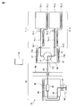
- FIG. 4 and 5 are schematic views showing an adhesive application device 70 according to the embodiment.
- FIG. 4 is a diagram showing the configuration of the coating apparatus 70
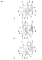
- FIGS. 5A to 5C are diagrams for explaining the operation of the coating apparatus 70.
- the coating apparatus 70 includes a switching unit 76, a first supply unit 71-1, a second supply unit 71-2, and a coating unit 82.
- the switching unit 76 includes a first receiving port 91A, a second receiving port 91B, and a sending port 91C, and the receiving port that communicates with the sending port 91C is one of the first receiving port 91A and the second receiving port 91B. Switch from one to the other.
- the first supply unit 71-1 supplies the first hot melt adhesive to the first receiving port 91A.
- the second supply unit 71-2 supplies a second hot melt adhesive different from the first hot melt adhesive to the second receiving port 91B.
- the application part 82 is connected to the delivery port 91C, and applies the first hot melt adhesive or the second hot melt adhesive delivered from the delivery port 91C to the material.
- the first supply unit 71-1 includes an adhesive storage tank 72-1, an adhesive supply pipe 74-1, a valve 73-1 and a heating unit 75-1.
- the adhesive storage tank 72-1 stores the first hot melt adhesive.
- the adhesive supply pipe 74-1 is a flow path dedicated to the first hot melt adhesive, and one end is connected to the adhesive storage tank 72-1 and the other end is connected to the first receiving port 91A of the switching unit 76. And exemplified by a hose.
- the valve 73-1 is disposed in the middle of the adhesive supply pipe 74-1, supplies or stops the first hot melt adhesive, and is exemplified by an electromagnetic valve.
- the heating unit 75-1 heats the first supply unit 71-1, brings the first hot melt adhesive to a predetermined temperature higher than the melting point, and is exemplified by an electric heater.
- the second supply unit 71-2 includes an adhesive storage tank 72-2, an adhesive supply pipe 74-2, a valve 73-2, and a heating unit 75-2.
- the adhesive storage tank 72-2 stores the second hot melt adhesive.
- the adhesive supply pipe 74-2 is a dedicated flow path for the second hot melt adhesive, and one end is connected to the adhesive storage tank 72-2 and the other end is connected to the second receiving port 91B of the switching unit 76. And exemplified by a hose.
- the valve 73-2 is disposed in the middle of the adhesive supply pipe 74-2, supplies or stops the second hot melt adhesive, and is exemplified by an electromagnetic valve.
- the heating unit 75-2 heats the second supply unit 71-2, brings the second hot melt adhesive to a predetermined temperature higher than the melting point, and is exemplified by an electric heater.
- the switching unit 76 has a three-way valve structure, for example, a ball valve.
- the switching unit 76 includes a switching structure 79, a first channel 77A, a second channel 77B, a third channel 77C, heat insulating plates 78-1 and 78-2, and a heating unit 81.
- the first channel 77A is a channel dedicated to the first hot melt adhesive, one end is the first receiving port 91A, and the other outlet 92A is in contact with the switching structure 79.
- the second flow path 77B is a flow path dedicated to the second hot melt adhesive, one end is the second receiving port 91B, and the other discharge port 92B is in contact with the switching structure 79.
- the third flow path 77C is a shared flow path for the first and second hot melt adhesives, one end is a delivery port 91C, and the other inlet port 92C is in contact with the switching structure 79.
- the switching structure 79 is a sphere arranged in a spherical space in the switching unit 76, and the outer surface of the sphere is in contact with the inner surface of the spherical space and is held so as to be rotatable (spinning). Inside the switching structure 79, a flow path shared by the first and second hot-melt adhesives is formed, and an in-valve flow path 80 having a substantially L shape and having inlets 93 and 94 at both ends is formed. .
- the heat insulating plates 78-1 and 78-2 thermally shut off the switching unit 76, the first supply unit 71-1 and the second supply unit 71-2, respectively.
- the heating unit 81 heats the switching unit 76 to bring the first and second hot melt adhesives to a predetermined temperature higher than the melting point, and is exemplified by an electric heater.
- the application unit 82 includes an adhesive delivery pipe 83, an application nozzle 84, and a heating unit 89.
- the adhesive delivery pipe 83 is a shared flow path for the first and second hot melt adhesives, and one end is connected to the delivery port 91C and the other end is connected to the application nozzle 84, and is exemplified by a hose.
- the application nozzle 84 includes an application head 88, an adhesive supply pipe 86, a filter 85, and a valve 87.
- the coating head 88 delivers the hot melt adhesive into a liquid or fine particle form and sends it to the material.
- the adhesive supply pipe 86 is a common flow path for the first and second hot melt adhesives, and connects the application head 88 and the adhesive delivery pipe 83.
- the filter 85 is disposed in the middle of the adhesive delivery pipe 83 and removes dust and the like in the hot melt adhesive.
- the valve 87 is disposed in the middle of the adhesive supply pipe 86 to supply or stop the hot melt adhesive, and is exemplified by an electromagnetic valve.
- the heating unit 89 heats the entire application unit 82 to bring the hot melt adhesive supplied to a predetermined temperature higher than the melting point, and is exemplified by an electric heater.
- the coating apparatus 70 further includes a control device 90 exemplified by a computer, and the control device 90 includes a first supply unit 71-1, a second supply unit 71-2, a switching unit 76, and a coating unit. 82 operation is controlled. Thereby, the coating device 70 can perform intermittent coating or contact coating.
- temperature sensors are installed in the first supply unit 71-1, the second supply unit 71-2, the switching unit 76, and the coating unit 82, and the heating units 75-1, 75-2, 81, 89 is controlled by the controller 90 based on the temperature of the temperature sensor.
- the switching unit 76 is a four-way valve or more, and three or more types of supply units 71 are provided.
- the method for switching the hot melt adhesive using the coating apparatus 70 is as follows. First, application of the first hot melt adhesive to the material is started (first adhesive application step). That is, the heating unit 75-1, the heating unit 81, and the heating unit 89 cause the first supply unit 71-1, the switching unit 76, and the coating unit 82 to have predetermined temperatures higher than the melting point of the first hot melt adhesive, respectively. To be heated. The valve 73-1 is opened, and the first hot melt adhesive is sent from the adhesive storage tank 72-1 and supplied to the first receiving port 91A of the switching unit 76 via the adhesive supply pipe 74-1. Then, it reaches the discharge port 92A via the first flow path 77A. At this time, as shown in FIG.
- the inlet / outlet port 94 of the in-valve channel 80 is connected to the discharge port 92A of the first channel 77A, and the inlet / outlet 93 is connected to the third channel.
- 77C inlet 92C is connected.
- the first hot melt adhesive reaches the delivery port 91C via the in-valve channel 80 and the third channel 77C.
- the first hot-melt adhesive reaches the valve 87 while the dust is removed by the filter 85 via the adhesive delivery pipe 83 and the adhesive supply pipe 86, and the valve 87 is opened.
- the first material is applied from the application head 88.
- the application of the first hot melt adhesive to the material stops. That is, the valve 73-1 is closed and the heating unit 75-1 stops heating (stopping process).
- second adhesive application step application of the second hot melt adhesive to the material is started (second adhesive application step). That is, the heating unit 75-2, the heating unit 81, and the heating unit 89 cause the second supply unit 71-2, the switching unit 76, and the coating unit 82 to have predetermined temperatures higher than the melting point of the second hot melt adhesive, respectively.
- the valve 73-2 is opened, and the second hot melt adhesive is sent from the adhesive storage tank 72-2 and supplied to the second receiving port 91B of the switching unit 76 via the adhesive supply pipe 74-2. Then, it reaches the discharge port 92B via the second flow path 77B. At this time, as shown in FIG.
- the inlet / outlet port 93 of the in-valve channel 80 is connected to the discharge port 92B of the second channel 77B, and the inlet / outlet 94 is connected to the third channel.
- 77C inlet 92C is connected.
- the second hot melt adhesive reaches the delivery port 91C via the in-valve channel 80 and the third channel 77C.
- the second hot melt adhesive reaches the valve 87 while the dust is removed by the filter 85 via the adhesive delivery pipe 83 and the adhesive supply pipe 86, and the valve 87 is opened. Then, it is applied from the application head 88 to the second material.
- the second hot melt adhesive is used at the start of the second adhesive application step (or during the stop step). It is preferable to perform a replacement step of extruding from the shared portion of the first hot melt adhesive and replacing with the second hot melt adhesive.
- the switching structure 79 is rotated so that both the inlets 93 and 94 at both ends of the valve flow path 80 are discharged from the discharge port 92A of the first flow path 77A.
- the switching unit 76 can be closed by preventing connection to the discharge port 92B of the second channel 77B and the inlet 92C of the third channel 77C.
- the volume of the flow path through which the first hot melt adhesive and the second hot melt adhesive flow in the switching unit 76, the adhesive delivery pipe 83 and the coating unit 82 is shared. It is preferable that either one of the first hot-melt adhesive and the second hot-melt adhesive in the adhesive supply pipe 74 is smaller than the volume of the channel through which it circulates exclusively.
- the volume of the flow path through which the hot melt adhesive flows in the in-valve flow path 80 and the third flow path 77C of the switching unit 76, the adhesive delivery pipe 83, and the adhesive supply pipe 86 of the application unit 82 is The volume of the flow path through which the first hot melt adhesive flows in the first flow path 77A and the adhesive supply pipe 74-1, and the second flow path 77B and the adhesive supply pipe 74 of the switching unit 76. -2 is preferably smaller than the volume of the flow path through which the second hot melt adhesive flows.
- first absorbent article 1 is manufactured using a first material (example: non-breathable sheet) for one material (example: back sheet) having the absorbent article. Then, the case where the 2nd material (example: breathable sheet) is used and the other types of 2nd absorbent article 1 is manufactured is demonstrated.
- the coating device 70 that applies the hot melt adhesive to the first material is the first supply unit 71.
- the switching unit 76 and the coating unit 82 are heated.
- the first receiving port 91A of the switching unit 76 is communicated with the sending port 91C.
- the first hot melt adhesive is supplied from the first supply unit 71-1 to the application unit 82 via the switching unit 76.
- the first hot melt adhesive is applied to the first material by the application unit 82 (first application process).
- the details of the first application step are as described in the first adhesive application step.
- the first supply unit 71-1 is stopped.
- the details of the stop of the first supply unit 71-1 are as in the above stop process.
- the 1st material is exchanged for the 2nd material, and manufacture of the 2nd absorptive article 1 is started.
- the second supply unit 71-1, the switching unit 76, and the coating unit 82 are heated. Subsequently, the second receiving port 91B of the switching unit 76 is communicated with the delivery port 91C, and the second hot melt adhesive is supplied to the coating unit 82 from the second supply unit 71-2 through the switching unit 76. To do. And the 2nd hot-melt-adhesive is apply
- the second supply unit 71-2 is heated before the end of the first application step. That is, it is preferable that the second hot-melt adhesive is sufficiently melted and applied immediately before the end of the first application step. Thereby, after the first application step is completed, the first hot melt adhesive can be immediately switched to the second hot melt adhesive, and thus the second application step can be immediately performed. Thereby, the time in switching of the hot melt adhesive can be suppressed.
- the hot melt adhesive is switched using the hot melt adhesive switching method using the coating device 70 described above. Is done.
- two supply units 71-1 and 71-2 capable of supplying two types of hot melt adhesives are provided, and the switching unit 76 provides two types of One of the hot melt adhesives is selected and applied to the material by one application part 82. Therefore, when the type of the absorbent article 1 to be manufactured is switched and the required hot melt adhesive is switched, the hot melt adhesive can be easily changed from one to the other only by switching the switching unit 76. Further, in order to use two types of hot-melt adhesives, it is possible to add another coating device by simply adding a set of supply parts 71 (e.g., an adhesive storage tank 72 and an adhesive supply pipe 74). There is no need to arrange them in parallel, saving space.
- a set of supply parts 71 e.g., an adhesive storage tank 72 and an adhesive supply pipe 74
- the application part 82 is shared by two types of hot-melt adhesives, it is not necessary to adjust the apparatus as compared with the case of using another application apparatus 70, and time and labor can be reduced. Furthermore, since switching of the coating device 70 is substantially unnecessary, time and labor can be reduced. Further, when the hot melt adhesive is switched, the application part 82 / switching part 76 shared by the two types of hot melt adhesives remains substantially heated, so that the previous hot melt adhesive is switched to the application part 82. Curing / adhesion at the portion 76 can be reduced.
- the hot-melt adhesive after switching it is possible to avoid a situation in which the hot-melt adhesive before curing and adhering is gradually peeled off and mixed as impurities into the hot-melt adhesive after switching. As a result, it is possible to prevent a situation in which the function and characteristics of the article due to impurities are reduced, defective products are produced, and the production yield is reduced.
- the application apparatus that is partially used in common is used. While suppressing the space, time, and labor in switching the melt adhesive, it is possible to suppress the entry of impurities into the hot melt adhesive and maintain the function and characteristics of the absorbent article.
- the coating device 70 has a first supply unit 71-1, Preferably, the second supply unit 71-2 and the switching unit 76 are disposed on the back side of the wall surface 99, and the coating unit 82 is disposed on the front side of the wall surface.
- the distance between the apparatus on the front side and the apparatus on the back side of the wall surface 99 is short, and the adjustment thereof is easy, and therefore the time and labor in switching the hot melt adhesive can be reduced.
- the back side of the wall surface 99 is used for installation of equipment, space is saved.
- the first and second hot melt adhesives may have different melting points.
- each device related to the application of the first hot melt adhesive is heated at a predetermined temperature higher than the melting point by each heating unit based on the melting point of the first hot melt adhesive.
- each device related to the application of the second hot melt adhesive is heated at a predetermined temperature higher than the melting point by each heating unit based on the melting point of the second hot melt adhesive.
- the predetermined temperature is a temperature at which each adhesive in each device melts.
- Each of the first application step and the second application step may include an intermittent application step of intermittently applying the hot melt adhesive to the material.
- intermittent application process of the first application process and the intermittent application process of the second application process common intermittent application control is performed by the application apparatus.
- the first application step and the second application step are common to the device that performs intermittent application, that is, the application device, and the control to perform intermittent application, that is, the operation of the application unit is common.
- the coating apparatus can be easily adjusted when the hot melt adhesive is switched.
- the application nozzle 84 may be a nozzle for contact application.
- the first hot melt adhesive is applied to the first material by the application nozzle 84 for contact application.
- the second hot melt adhesive is applied to the second material by the contact application nozzle 84 for contact application.
- the hot melt adhesive since the hot melt adhesive is applied to the material by the application nozzle 84 for contact type application, the influence of the remaining adhesion of the hot melt adhesive on the nozzle that may occur in the application nozzle for non-contact type application is affected. Can be reduced. Thereby, the hot melt adhesive can be easily switched, and time and labor can be suppressed.
- FIG. 6 is a diagram showing an absorbent article 51 (disposable diaper) according to the present embodiment, and specifically shows a plan view in a state where the absorbent article 51 is expanded and expanded.
- the absorbent article 51 has a back waistline region S2 corresponding to the waistline of the wearer, an abdomen waistline region S1 corresponding to the waistline of the wearer, and the inseam of the wearer.
- it has a crotch region S3 located between the back waistline region S2 and the ventral waistline region S1.
- the absorbent article 51 is mounted as a diaper by connecting a fastening tape (described later) at both ends in the width direction W of the back waistline region S2 and a target tape (described later) in the width direction W center of the abdominal waistline region S1. Is done.
- a direction toward the back waistline region S2 and a direction toward the abdominal waistline region S1 in the longitudinal direction L are also referred to as a rear side direction and a front side direction, respectively.
- the absorbent article 51 includes a liquid-permeable top sheet 52 positioned on the skin side, a liquid-impermeable back sheet 53 positioned on the non-skin side, and a liquid positioned between the top sheet 52 and the back sheet 53. And an absorbent 54 having liquid absorbability and liquid retention.
- the absorber 54 and the top sheet 52 and the absorber 54 and the back sheet 53 are joined by an adhesive, and the top sheet 52 and the back sheet 53 are joined by an adhesive at their peripheral portions.
- the absorbent article 51 further includes a pair of leak-proof walls 55, 55, leg stretch members 56, 56, an exterior sheet 59, a stretch member 61, and a pair of protrusions 57, 57 including a fastening tape 57a.
- the target tape 62 and a pair of protrusions 58 and 58 are provided.
- the exterior sheet 59 and the back sheet 53, the leak-proof wall 55 and the surface sheet 52 and the exterior sheet 59, and the elastic member 61 and the exterior sheet 59 are bonded to each other by an adhesive.
- FIG. 7 is a schematic diagram showing a configuration of an absorbent article manufacturing apparatus 600 according to the embodiment.
- the manufacturing apparatus 600 includes a first forming unit 600A to a fourth forming unit 600D, and a control device 600X exemplified by a computer.
- the manufacturing method of the absorbent article using the manufacturing apparatus 600 includes a first forming process performed by the first forming unit 600A to a fourth forming process performed by the fourth forming unit 600D.
- the control device 600X controls the operation of the manufacturing device 600.
- the rotary drum 411 is rotated by the fiber stacking device 410, and the fiber material supplied from the material supplier 413 is deposited in the groove communicating with the negative pressure chamber 411N of the pattern plate 412. An accumulated fiber is formed inside.
- the pattern plate 412 reaches the positive pressure chamber 411P together with the piled body, the piled body is detached from the pattern plate 412.
- a continuous sheet-like lower layer tissue sheet LT is supplied from the roll WR1 to the transport belt 415.
- a hot melt adhesive is applied to one surface of the lower layer tissue sheet LT by a coating device 601.
- the stacked body is pressed onto one surface of the lower layer tissue sheet LT on the transport belt 415 via a hot melt adhesive, thereby forming a first semi-finished product P21.
- the first semi-finished product P21 is transported by the transport belt 415 while being sucked by the suction device 416.
- a continuous sheet-like upper tissue sheet UT is supplied from the roll WR2 to the transport belt 415.
- a hot melt adhesive is applied to one surface of the upper tissue sheet UT by a coating device 602.
- one surface of the upper layer tissue sheet UT is pressed against the first semi-finished product P21 on the transport belt 415 via a hot melt adhesive to form a second semi-finished product P22.
- the second semi-finished product P22 is cut into the shape of the absorber 54 by the cutting device 420, and the third semi-finished product P23 that is the absorber 54 is formed.
- the third semi-finished product P23 is supplied to the joining rolls 460 and 461 via the transport roll 421.
- the continuous sheet-like topsheet TS is supplied from the roll WR3 to the joining roll 430.
- a hot melt adhesive is applied to one surface of the top sheet TS by a coating device 603.
- a pair of leak-proof wall sheets GS, GS in the form of continuous sheets are supplied from the rolls WR4, WR5 to the joining roll 430.
- the pair of leakage barrier sheets GS and GS are pressed against the surface of the surface sheet TS to which the hot melt adhesive is applied to form the surface sheet TS in which the pair of leakage barrier sheets GS and GS are joined.
- a hot melt adhesive is applied to the other surface of the top sheet TS opposite to the surface on which the leak-proof wall sheets GS and GS are bonded by the coating device 604 and supplied to the bonding rolls 460 and 461. .
- a continuous sheet-like back sheet BS is supplied from the roll WR6 to the joining roll 440.
- a continuous sheet-like exterior sheet ES (with leg elastic members 56, protrusions 57 and 58, and target tape 62 already added) is supplied from the roll W7 to the joining roll 440.
- a hot melt adhesive is applied to one surface of the exterior sheet ES by a coating device 605. Then, the back sheet BS is pressed against the surface of the exterior sheet ES to which the hot melt adhesive is applied, and the back sheet BS to which the exterior sheet ES is bonded is formed.
- a hot melt adhesive for the absorber 54 is applied by the coating device 606 to the other surface opposite to the surface to which the exterior sheet ES is bonded, and the elastic member 61 is coated by the coating device 607.
- a hot melt adhesive is applied and supplied to the joining roll 460.
- the continuous sheet-like elastic member sheet EW is supplied from the roll WR8 to the cutting device 450 and cut into a predetermined shape.
- the stretchable member 61 that is a cut piece is delivered to the widening pasting device 451, both ends are stretched in the width direction by the widening pasting device 451, and stretched on the adhesive application surface of the back sheet BS on the joining roll 460. It is pasted.
- the back surface sheet BS to which the elastic member 11 is attached moves on the joining roll 460 to the joining roll 461.
- the third semi-finished product P23 in the first forming step, the top sheet TS in the second forming step, and the back sheet BS in the third forming step are a pair of bonding rolls. 460 and 461 are compressed in the thickness direction and joined. Thereby, the continuous body P24 of the absorbent article 51 is formed.
- the continuous body P24 of the absorbent article 51 is cut by the cutting device 470 to form the absorbent article P25, that is, the absorbent article 51.
- the packaging process is omitted. As described above, the packaged absorbent article 51 is manufactured.
- At least one of the coating apparatuses 601 to 607 is the coating apparatus 70 shown in FIG.
- This manufacturing method is the same as the manufacturing method of the absorbent article 1 using the hot melt adhesive switching method using the coating apparatus 70 in the first embodiment. Therefore, the description of this manufacturing method is omitted. Also in this manufacturing method, the same operational effects as those of the manufacturing method of the absorbent article 1 using the hot melt adhesive switching method using the coating apparatus 70 in the first embodiment can be obtained.
- the absorbent article of the present invention is not limited to the above-described embodiments, and can be appropriately combined and changed without departing from the object and spirit of the present invention.
Landscapes
- Health & Medical Sciences (AREA)
- Epidemiology (AREA)
- Engineering & Computer Science (AREA)
- General Health & Medical Sciences (AREA)
- Heart & Thoracic Surgery (AREA)
- Vascular Medicine (AREA)
- Life Sciences & Earth Sciences (AREA)
- Animal Behavior & Ethology (AREA)
- Biomedical Technology (AREA)
- Public Health (AREA)
- Veterinary Medicine (AREA)
- Manufacturing & Machinery (AREA)
- Absorbent Articles And Supports Therefor (AREA)
- Coating Apparatus (AREA)
- Application Of Or Painting With Fluid Materials (AREA)
- Adhesives Or Adhesive Processes (AREA)
Abstract
複数種類の吸収性物品を一つの製造ラインで製造する際、ホットメルト接着剤の切り替え時間等を抑制しつつ、ホットメルト接着剤への不純物の混入を抑える。吸収性物品の製造方法は、塗布装置を含む一つの製造ラインで複数種類の吸収性物品を製造する。塗布装置(70)は、第1のホットメルト接着剤を供給する第1の供給部(71-1)と、第2のホットメルト接着剤を供給する第2の供給部(71-2)と、第1及び第2の供給部のいずれか一方を選択する切替部(76)と、第1又は前記第2のホットメルト接着剤を資材に塗布する塗布部(82)と、を備える。製造方法は、第1の吸収性物品の製造にて、切替部で第1の供給部を選択し、塗布部により第1のホットメルト接着剤を第1の資材に塗布する工程と、第2の吸収性物品の製造にて、切替部で第2の供給部を選択し、塗布部により第2のホットメルト接着剤を第2の資材に塗布する工程と、備える。
Description
本発明は吸収性物品の製造方法及び接着剤の塗布装置に関する。
生理用ナプキンや使い捨ておむつのような吸収性物品が知られている。吸収性物品を構成する資材の多くは他の資材とホットメルト接着剤で接着されている。すなわち、一つの吸収性物品には、複数の箇所にホットメルト接着剤が使用されている。したがって、吸収性物品の製造では、ホットメルト接着剤の塗布の工程が相対的に多く、それに伴って、製造ラインでは、ホットメルト接着剤の塗布装置の台数が多く、占有する領域が広いということができる。
ホットメルト接着剤の塗布に適用可能な塗布装置としては、例えば特許文献1の間欠塗布装置が挙げられる。この間欠塗布装置は、搬送方向に搬送される塗布対象物の表面に間欠的に塗布剤を塗布する装置であり、一つの塗布ノズルに対して一つの塗布液タンクを備え、一種類の接着剤を塗布することができる。
吸収性物品において、例えば資材の種類が互いに異なること等の理由により、その資材用のホットメルト接着剤が互いに異なるような複数種類の吸収性物品が存在する。例えば、生理用ナプキンにおいて、裏面シートの種類が通気性シートと非通気性シートのように互いに異なることにより、通気性シート用及び非通気性シート用のホットメルト接着剤が互いに異なるような複数種類の生理用ナプキンが存在する。あるいは、裏面シートは同じだが要求される接着強度の相違により、高接着強度用及び低接着強度用のホットメルト接着剤が互いに異なるような複数種類の生理用ナプキンが存在する。
このような複数種類の吸収性物品を、一つの製造ラインで時間帯をずらして製造する場合がある。すなわち、その製造ラインで、ある時間帯に一種類の吸収性物品を連続的に製造した後、同じ製造ラインで、他の時間帯に他の一種類の吸収性物品を連続的に製造する、というような場合である。その場合、製造される吸収性物品の種類に応じて、ホットメルト接着剤を変更する必要が生じる。
ホットメルト接着剤の変更方法としては、特許文献1のような塗布装置を用いている場合には、ホットメルト接着剤の変更に応じて塗布装置を他の塗布装置に取り替える方法が考えられる。ホットメルト接着剤ごとに異なる塗布装置を使用することで、あるホットメルト接着剤が他のホットメルト接着剤と混ざってしまうというホットメルト接着剤の汚染を防止することができる。しかし、その場合、複数の塗布装置が設置され、それゆえ混み合っている製造ライン内で、前の塗布装置を取り外し、次の塗布装置を取り付ける必要があり、時間や手間がかかる。加えて、次の塗布装置は、前の塗布装置と同種の装置であっても、細部の構成の状態、例えば弁やノズルの状態が同じではないため調整を行う必要があり、その点でも時間や手間がかかる。
また、ホットメルト接着剤の変更を考慮して、特許文献1のような塗布装置を予めもう一台並列に製造ラインに追加しておく方法も考えられる。この場合にも、ホットメルト接着剤の汚染を防止することができる。しかし、複数の塗布装置が設置され混み合っている製造ラインに追加の塗布装置を設置するスペースの確保が難しい。仮に、追加の塗布装置を設置できたとしても、当該装置と他の機器・装置との距離が近くなり、他の機器・装置の調整等が行い難くなる。加えて、追加の塗布装置は、使用されていなくても経時的に弁やノズルの状態が変化し、応答特性などが変動してしまうので、使用を開始するときに改めて調整を行う必要があり、時間や手間がかかる。
一方、スペースや時間や手間を削減するために、特許文献1のような塗布装置において、塗布装置全体を切り替えるのではなく、塗布液タンクのみを切り替える方法も考えられる。その場合、塗布液タンクの切り替えは室温で行うことになるが、そのときに前のホットメルト接着剤が硬化して、管や弁などに付着してしまうおそれがある。そうなると、塗布液タンクの切り替え後にホットメルト接着剤を使用するとき、管や弁などに付着した前のホットメルト接着剤が少しずつ剥がれて不純物として切り替え後のホットメルト接着剤に混ざり込んで、吸収性物品に塗布されることになる。そうなると、資材の一部が剥がれたり、変色したり、反応したりすることなどによる吸収性物品の機能や性能が低下し、不良品が生じて、製造歩留りが低下するおそれがある。
本発明の目的は、複数種類の吸収性物品を一つの製造ラインで製造する場合において、異なる種類の吸収性物品を製造するとき、当該吸収性物品の種類に応じてホットメルト接着剤を切り替えるときのスペース・時間・手間を抑制しつつ、ホットメルト接着剤への不純物の混入を抑えて吸収性物品の機能や特性を維持することが可能な吸収性物品の製造方法及び接着剤の塗布装置を提供することにある。
本発明の吸収性物品の製造方法は次のとおりである。(1)吸収性物品を構成する複数の資材がホットメルト接着剤で接着され、前記複数の資材のうちの少なくとも一つに対応するホットメルト接着剤が互いに異なる複数種類の吸収性物品を、接着剤の塗布装置を含む一つの製造ラインで製造可能な吸収性物品の製造方法であって、前記塗布装置は、第1の受入口、第2の受入口及び送出口を備え、前記送出口に連通する受入口を前記第1の受入口及び前記第2の受入口のいずれか一方から他方へ切り替える切替部と、第1のホットメルト接着剤を前記第1の受入口に供給する第1の供給部と、前記第1のホットメルト接着剤と異なる第2のホットメルト接着剤を前記第2の受入口に供給する第2の供給部と、前記送出口に接続され、前記送出口から送出される前記第1のホットメルト接着剤又は前記第2のホットメルト接着剤を資材に塗布する塗布部と、を備えており、前記製造方法は、前記複数種類の吸収性物品のうちの第1の吸収性物品の製造において、前記第1の供給部、前記切替部及び前記塗布部を加熱し、前記切替部の前記第1の受入口を前記送出口に連通して、前記塗布部により前記第1のホットメルト接着剤を第1の資材に塗布する第1の塗布工程と、前記複数種類の吸収性物品のうちの第2の吸収性物品の製造において、前記第2の供給部、前記切替部及び前記塗布部を加熱し、前記切替部の前記第2の受入口を前記送出口に連通して、前記塗布部により前記第2のホットメルト接着剤を前記第2の資材に塗布する第2の塗布工程と、備える、吸収性物品の製造方法。
本吸収性物品の製造方法は、上記構成により、製造される吸収性物品の種類が変更されたとき、切替部を切り替えるだけで、ホットメルト接着剤を容易に変更できる。このとき、本製造方法では、実質的に供給部を一式追加するだけでよく、塗布装置をもう一台並列に配置したりする必要が無いので、省スペースである。また、本製造方法では、塗布部は二種類のホットメルト接着剤に共有されるので、塗布装置そのものを切り替えたり、追加の塗布装置を用いたりする場合と比較して、調整をほとんど行う必要が無くなり、時間や手間を削減できる。更に、本製造方法では、機器の切り替えは実質的に不要であるため、塗布装置そのものを切り替える場合と比較して、時間や手間を削減できる。一方、ホットメルト接着剤の切り替え時において、二種類のホットメルト接着剤に共有される塗布部・切替部は実質的に加熱されたままであるので、前のホットメルト接着剤が塗布部・切替部にて硬化・付着することを低減できる。それにより、切り替え後のホットメルト接着剤の使用時に、硬化・付着した前のホットメルト接着剤が少しずつ剥がれて不純物として切り替え後のホットメルト接着剤に混ざり込む、という事態を回避できる。その結果、不純物による吸収性物品の機能や特性が低下し、不良品が生じて、製造歩留りが低下する、という事態を防止できる。このように本製造方法では、二種類のホットメルト接着剤のいずれか一方を資材に塗布するとき、一部が共通に使用される塗布装置を用いることで、ホットメルト接着剤の切り替えにおけるスペース・時間・手間を抑制しつつ、ホットメルト接着剤への不純物の混入を抑えて、吸収性物品の機能や特性を維持することが可能となる。
本発明の吸収性物品の製造方法は(2)前記第1のホットメルト接着剤と前記第2のホットメルト接着剤とは互いに異なる融点を有し、前記第1の塗布工程では、前記第1の供給部、前記切替部及び前記塗布部が、前記第1のホットメルト接着剤の融点に基づいて、当該融点よりも高い温度で加熱され、前記第2の塗布工程では、前記第2の供給部、前記切替部及び前記塗布部が、前記第2のホットメルト接着剤の融点に基づいて、当該融点よりも高い温度で加熱される、上記(1)に記載の吸収性物品の製造方法であってもよい。
本吸収性物品の製造方法では、上記構成により、ホットメルト接着剤の相違に伴い、ホットメルト接着剤の融点が相違しても、ホットメルト接着剤が移動途中の管や弁で硬化・付着することを防止でき、ホットメルト接着剤への不純物の混入を抑えて、吸収性物品の機能や特性を維持できる。また、融点の異なる様々なホットメルト接着剤を塗布に使用できるので、吸収性物品の機能や特性の維持に適したホットメルト接着剤を選択でき、ホットメルト接着剤の選択の自由度や資材や第2の資材の選択の自由度を高められる。
本吸収性物品の製造方法では、上記構成により、ホットメルト接着剤の相違に伴い、ホットメルト接着剤の融点が相違しても、ホットメルト接着剤が移動途中の管や弁で硬化・付着することを防止でき、ホットメルト接着剤への不純物の混入を抑えて、吸収性物品の機能や特性を維持できる。また、融点の異なる様々なホットメルト接着剤を塗布に使用できるので、吸収性物品の機能や特性の維持に適したホットメルト接着剤を選択でき、ホットメルト接着剤の選択の自由度や資材や第2の資材の選択の自由度を高められる。
本発明の吸収性物品の製造方法は(3)前記第2の塗布工程において、前記第2の供給部は前記第1の塗布工程の終了する前から加熱される、上記(1)又は(2)に記載の吸収性物品の製造方法であってもよい。
本吸収性物品の製造方法では、上記構成により、第1の塗布工程の終了直後に、第2のホットメルト接着剤を十分に溶融させて塗布可能にできる。それにより、第1のホットメルト接着剤から第2のホットメルト接着剤へ直ちに切り替えられ、よって第2の塗布工程に直ちに移行できる。すなわちホットメルト接着剤の切り替え時間を抑制できる。
本吸収性物品の製造方法では、上記構成により、第1の塗布工程の終了直後に、第2のホットメルト接着剤を十分に溶融させて塗布可能にできる。それにより、第1のホットメルト接着剤から第2のホットメルト接着剤へ直ちに切り替えられ、よって第2の塗布工程に直ちに移行できる。すなわちホットメルト接着剤の切り替え時間を抑制できる。
本発明の吸収性物品の製造方法は(4)前記製造ラインの機器は壁面の表側に取り付けられており、前記第1の供給部、前記第2の供給部及び前記切替部は前記壁面の裏側に配置され、前記塗布部は前記壁面の表側に配置される、上記(1)乃至(3)のいずれか一項に記載の吸収性物品の製造方法であってもよい。
本吸収性物品の製造方法では、上記構成により、壁面の表側の塗布部と第1の供給部、第2の供給部及び切替部との距離が近く、それらの調整が容易であり、よってホットメルト接着剤の切り替えにおける時間・手間を低減できる。また、壁面の裏側を第1の供給部、第2の供給部及び切替部の設置スペースに用いているので表側が省スペースである。
本吸収性物品の製造方法では、上記構成により、壁面の表側の塗布部と第1の供給部、第2の供給部及び切替部との距離が近く、それらの調整が容易であり、よってホットメルト接着剤の切り替えにおける時間・手間を低減できる。また、壁面の裏側を第1の供給部、第2の供給部及び切替部の設置スペースに用いているので表側が省スペースである。
本発明の吸収性物品の製造方法は(5)前記第1の供給部及び前記第2の供給部の各々は、接着剤貯蔵タンクと、前記接着剤貯蔵タンクと前記切替部とを接続する接着剤供給管と、を含み、前記塗布部は、塗布ノズルと、前記塗布ノズルと前記切替部とを接続する接着剤送出管と、を含み、前記切替部、前記接着剤送出管及び前記塗布ノズルにおける前記第1のホットメルト接着剤及び前記第2のホットメルト接着剤が共用で流通する流路の容積は、前記切替部及び前記接着剤供給管における前記第1のホットメルト接着剤及び前記第2のホットメルト接着剤のいずれか一方が専用で流通する流路の容積よりも小さく、前記第2の塗布工程は、前記切替部、前記接着剤送出管及び前記塗布ノズル内の前記第1のホットメルト接着剤を、前記第2の供給部の前記接着剤供給管から供給される前記第2のホットメルト接着剤で押し出して、前記第2のホットメルト接着剤に置き替える置き替え工程を含む、上記(1)乃至(4)のいずれか一項に記載の吸収性物品の製造方法であってもよい。
本吸収性物品の製造方法では、上記構成により、置き替え工程において、押し出す第2のホットメルト接着剤の量を少なくでき、共用される部分から第1のホットメルト接着剤を除去できる。それにより、置き替え工程に必要な時間を短くでき、ホットメルト接着剤の切り替えの時間・手間を削減できると共に、ホットメルト接着剤を切り替えることができ、第2のホットメルト接着剤への不純物の混入を抑えることができる。
本吸収性物品の製造方法では、上記構成により、置き替え工程において、押し出す第2のホットメルト接着剤の量を少なくでき、共用される部分から第1のホットメルト接着剤を除去できる。それにより、置き替え工程に必要な時間を短くでき、ホットメルト接着剤の切り替えの時間・手間を削減できると共に、ホットメルト接着剤を切り替えることができ、第2のホットメルト接着剤への不純物の混入を抑えることができる。
本発明の吸収性物品の製造方法は(6)前記第1の塗布工程及び前記第2の塗布工程の各々は、前記ホットメルト接着剤を前記資材に間欠的に塗布する間欠塗布工程を含み、
前記第1の塗布工程の前記間欠塗布工程と、前記第2の塗布工程の前記間欠塗布工程とでは、前記塗布装置により共通の間欠塗布制御が行われる、上記(1)乃至(5)のいずれか一項に記載の吸収性物品の製造方法であってもよい。
本吸収性物品の製造方法では、第1の塗布工程と第2の塗布工程とでは、間欠塗布を行う機器、すなわち塗布部の構造が共通であり、かつ、間欠塗布を行う制御、すなわち塗布部の動作が共通なので、間欠塗布を行う機器及び制御が相違する別々の塗布装置を用いる場合より、ホットメルト接着剤の切り替えのときの塗布装置の調整が容易にできる。
前記第1の塗布工程の前記間欠塗布工程と、前記第2の塗布工程の前記間欠塗布工程とでは、前記塗布装置により共通の間欠塗布制御が行われる、上記(1)乃至(5)のいずれか一項に記載の吸収性物品の製造方法であってもよい。
本吸収性物品の製造方法では、第1の塗布工程と第2の塗布工程とでは、間欠塗布を行う機器、すなわち塗布部の構造が共通であり、かつ、間欠塗布を行う制御、すなわち塗布部の動作が共通なので、間欠塗布を行う機器及び制御が相違する別々の塗布装置を用いる場合より、ホットメルト接着剤の切り替えのときの塗布装置の調整が容易にできる。
本発明の吸収性物品の製造方法は(7)前記塗布部は、接触式塗布用の塗布ノズルを含み、前記第1の塗布工程は、前記第1のホットメルト接着剤を前記接触式塗布用の塗布ノズルで前記第1の資材に接触塗布し、前記第2の塗布工程は、前記第2のホットメルト接着剤を前記接触式塗布用の塗布ノズルで前記第2の資材に接触塗布する、上記(1)乃至(6)のいずれか一項に記載の吸収性物品の製造方法であってもよい。
本吸収性物品の製造方法では、接触式塗布用の塗布ノズルでホットメルト接着剤を資材に塗布しているので、非接触式塗布用の塗布ノズルで起こりうるノズルに対するホットメルト接着剤の付着残りの影響を低減できる。それにより、ホットメルト接着剤の切り替えを容易に行うことができ、時間・手間を抑制することができる。
本吸収性物品の製造方法では、接触式塗布用の塗布ノズルでホットメルト接着剤を資材に塗布しているので、非接触式塗布用の塗布ノズルで起こりうるノズルに対するホットメルト接着剤の付着残りの影響を低減できる。それにより、ホットメルト接着剤の切り替えを容易に行うことができ、時間・手間を抑制することができる。
本発明の接着剤の塗布装置は、以下のとおりである。(8)第1の受入口、第2の受入口及び送出口を備え、前記送出口に連通する受入口を前記第1の受入口及び前記第2の受入口のいずれか一方から他方へ切り替える切替部と、第1のホットメルト接着剤を前記第1の受入口に供給する第1の供給部と、前記第1のホットメルト接着剤と異なる第2のホットメルト接着剤を前記第2の受入口に供給する第2の供給部と、前記送出口に接続され、前記送出口から送出される前記第1のホットメルト接着剤又は前記第2のホットメルト接着剤を資材に塗布する塗布部と、を備える、接着剤の塗布装置。
本接着剤の塗布装置では、上記構成により、製造される物品の種類が変更されたとき、切替部を切り替えるだけで、ホットメルト接着剤を容易に変更できる。このとき、本塗布装置では、実質的に供給部を一式追加するだけでよく、塗布装置をもう一台並列に配置したりする必要が無いので、省スペースである。また、本塗布装置では、塗布部は二種類のホットメルト接着剤に共有されるので、塗布装置そのものを切り替えたり、追加の塗布装置を用いたりする場合と比較して、調整をほとんど行う必要が無くなり、時間や手間を削減できる。更に、本塗布装置では、機器の切り替えは実質的に不要であるため、塗布装置そのものを切り替える場合と比較して、時間や手間を削減できる。一方、ホットメルト接着剤の切り替え時において、二種類のホットメルト接着剤に共有される塗布部・切替部は実質的に加熱されたままであるので、前のホットメルト接着剤が塗布部・切替部にて硬化・付着することを低減できる。それにより、切り替え後のホットメルト接着剤の使用時に、硬化・付着した前のホットメルト接着剤が少しずつ剥がれて不純物として切り替え後のホットメルト接着剤に混ざり込む、という事態を回避できる。その結果、不純物による物品の機能や特性が低下し、不良品が生じて、製造歩留りが低下する、という事態を防止できる。このように本塗布装置では、二種類のホットメルト接着剤のいずれか一方を資材に塗布するとき、一部が共通に使用される塗布装置を用いることで、ホットメルト接着剤の切り替えにおけるスペース・時間・手間を抑制しつつ、ホットメルト接着剤への不純物の混入を抑えて、物品の機能や特性を維持することが可能となる。
本発明により、複数種類の吸収性物品を一つの製造ラインで製造する場合において、異なる種類の吸収性物品を製造するとき、当該吸収性物品の種類に応じてホットメルト接着剤を切り替えるときのスペース・時間・手間を抑制しつつ、ホットメルト接着剤への不純物の混入を抑えて吸収性物品の機能や特性を維持することが可能な吸収性物品の製造方法及び接着剤の塗布装置を提供することが可能となる。
(第1の実施の形態)
以下、本実施の形態に係る吸収性物品の製造方法及び塗布装置について、吸収性物品の例として生理用ナプキンを用いて説明する。ただし、本発明の吸収性物品はその例に限定されるものではなく、本発明の範囲を逸脱しない限り、他の吸収性物品であってもよい。
以下、本実施の形態に係る吸収性物品の製造方法及び塗布装置について、吸収性物品の例として生理用ナプキンを用いて説明する。ただし、本発明の吸収性物品はその例に限定されるものではなく、本発明の範囲を逸脱しない限り、他の吸収性物品であってもよい。
吸収性物品1の構成を説明する。図1及び図2は吸収性物品1を展開した状態の平面図及び分解斜視図である。吸収性物品1は、吸収性物品本体1Aと包装シート1Bとを有し、吸収性物品本体1Aが略矩形状の包装シート1Bに取り外し可能に固定される。吸収性物品本体1Aは、互いに直交する長手方向L、幅方向W及び厚さ方向Hを有し、幅方向Wの中心を通り長手方向Lに延びる中央軸線CLと、一対のフラップ部2b、2b(後述)の長手方向Lの中心を通り幅方向Wに延びる中央軸線CWを有する。図1で、向かって上方及び下方がそれぞれ吸収性物品本体1Aの前方及び後方である。吸収性物品本体1Aの長手方向L及び幅方向Wと包装シート1Bの長手方向及び幅方向とは一致するので、吸収性物品本体1A及び包装シート1Bに共通に長手方向L及び幅方向Wを用いる。また、本明細書において、展開して平坦に拡げた状態の吸収性物品1又は吸収性物品本体1Aを上面側から厚さ方向に見ることを単に「平面視」という。「肌側」及び「非肌側」とは、吸収性物品本体1Aの着用者が吸収性物品本体1Aを着用したとき、厚さ方向Hにおいて相対的に着用者の肌面に近い側及び遠い側をそれぞれ意味する。また、中央軸線CLに向かう方向及び遠ざかる方向を、それぞれ幅方向Wの内側及び外側の方向とする。中央軸線CWに向かう方向及び遠ざかる方向を、長手方向Lの内側及び外側の方向とする。
吸収性物品本体1A(生理用ナプキン)は、長手方向Lに延びる本体部2aと、長手方向Lの略中央部に幅方向Wの両側に延出する一対のフラップ部2b、2bとを備え、本体部2aの排泄口当接域の周囲に圧搾部2Eを有する。吸収性物品本体1Aは、少なくとも、着用者の肌側に位置する液透過性の表面シート2と、着用者の非肌側に位置する液不透過性の裏面シート3と、表面シート2及び裏面シート3との間に位置する液吸収性及び液保持性の吸収体4とで構成される。表面シート2としては、例えば液透過性の不織布や織布、液透過孔が形成された合成樹脂フィルム、これらの複合シートなど任意の液透過性シートが挙げられる。裏面シート3としては、例えば液不透過性の不織布や合成樹脂フィルム、これらの複合シート、SMS不織布など任意の液不透過性シートが挙げられる。裏面シート3は、着用時の蒸れを低減させるために、液不透過性に加えて、通気性又は透湿性を有する場合がある。裏面シート3の非肌側には、裏面シート3を補強し、手触りを改善する外装シート9が積層されてもよい。外装シート9としては、裏面シート3と同様の材料を用い得る。吸収体4は、本実施の形態では、肌側の上層コアラップ4Uと、非肌側の下層コアラップ4Lと、上層コアラップ4Uと下層コアラップ4Lとの間に位置する吸収性コア4Aとを含む。吸収体4又は吸収性コア4Aとしては、例えばパルプ繊維、合成繊維、吸収性ポリマなどが挙げられる。上層コアラップ4U及び下層コアラップ4Lとしては、例えば不織布やティッシュが挙げられる。ただし、吸収性物品本体1Aはこの構成に限定されず、吸収性物品1で一般的に使用される公知の構成を用いることができる。
吸収体4と表面シート2とは互いに所定パターン(図示されず)の接着剤45により接合され、吸収体4と裏面シート3とは互いに所定パターン(図示されず)の接着剤46により接合される。また、表面シート2と裏面シート3はそれらの周縁部分にて互いに所定パターン(図示されず)の接着剤45、46により接合される。更に、吸収性コア4Aと上層コアラップ4Uとは互いに所定パターン(図示されず)の接着剤43により接合され、吸収性コア4Aと下層コアラップ4Lとは互いに所定パターン(図示されず)の接着剤44により接合される。また、上層コアラップ4Uと下層コアラップ4Lはそれらの周縁部分にて互いに所定パターン(図示されず)の接着剤43、44により接合される。
吸収性物品本体1Aの本体部2aは裏面シート3の非肌側に固定部42を備える。固定部42は幅方向Wに所定の幅で長手方向Lに延設される。吸収性物品本体1Aの各フラップ部2bは裏面シート3の非肌側に他の固定部41を備える。他の固定部41は幅方向Wに所定の幅で長手方向Lに延設される。固定部41、42としては例えば粘着性の接着剤が用いられる。吸収性物品本体1Aは固定部41、42を介して包装シート1Bに固定される。包装シート1Bはそれら固定部41、42と接する部分にそれぞれ剥離シート31、32を有し、吸収性物品本体1Aは包装シート1Bに剥離可能に固定される。剥離シート31、32と包装シート1Bとは互いに所定パターン(図示されず)の接着剤47で接合される。ただし、固定部41、42はその形状に限定されるものでは無く、吸収性物品1で一般的に使用される公知の形状や数を用いることができる。
上記の各接着剤の材料としては、熱可塑性樹脂接着剤のような吸収性物品1で一般的に使用される公知の接着剤の材料が使用されるが、少なくとも一つはホットメルト接着剤が使用される。その各ホットメルト接着剤の材料については、吸収性物品1に一般的に使用される公知のホットメルト接着剤の材料を使用でき、例えばポリオレフィン系(PE系、EVA系、EEA系、APP系、APO系など)、合成ゴム系(SIS系、SBSS系など)などが挙げられる。所望の特性(例示:粘度、軟化点、安定性など)を得るため、添加剤(例示:粘着付与剤、可塑剤、酸化防止剤など)を付与してもよい。ホットメルト接着剤の材料(種類)は所望の特性や適用される資材との相性などにより適宜変更される。このようなホットメルト接着剤は材料や添加剤などの相違によって融点が相違する。
吸収性物品本体1Aと包装シート1Bとは、吸収性物品本体1Aが包装シート1Bに固定された状態で、長手方向Lに平行に延びる複数の折り線FLT1、FLT2の位置で折り畳まれ、幅方向Wに平行に延びる複数の折り線FLV1、FLV2、FLV2’の位置で折り畳まれる。包装シート1Bにおける長手方向Lの前方側の端部に、粘着性のリードテープ35が貼り付けられる。包装シート1Bの材料としては、吸収性物品本体1Aを包装用に一般的に使用される公知の材料、例えば樹脂フィルムや紙、不織布が挙げられる。
次に、吸収性物品1の製造方法を説明する。図3は吸収性物品1の製造装置300の構成を示す模式図である。製造装置300は、第1の形成ユニット300Aと、第2の形成ユニット300Bと、第3の形成ユニット300Cと、第4の形成ユニット300Dと、コンピューターに例示される制御装置300Xと、を備える。製造装置300を用いた吸収性物品の製造方法は、第1の形成ユニット300Aが実行する第1の形成工程と、第2の形成ユニット300Bが実行する第2の形成工程と、第3の形成ユニット300Cが実行する第3の形成工程と、第4の形成ユニット300Dが実行する第4の形成工程と、を備える。制御装置300Xは製造装置300の動作を制御する。
第1の形成工程では、積繊装置110の回転ドラム111が回転され、材料供給器113から供給された積繊材料がパターンプレート112の負圧室111Nに連通した溝内に堆積し、溝内に積繊体ABが形成される。次に、パターンプレート112が積繊体ABと共に正圧室111Pに到達すると、積繊体ABがパターンプレート112から離脱される。一方、連続シート状の上層ティッシュシートUTがロールWR1から搬送ベルト115に供給される。上層ティッシュシートUTの一方の面には塗布装置301によりホットメルト接着剤(接着剤43に対応)が塗布されている。そして、積繊体ABは、搬送ベルト115上の上層ティッシュシートUTの一方の面の上に押し付けられる。それにより第1の半製品P1が形成される。第1の半製品P1はサクション装置116で吸引され搬送ベルト115で搬送される。次に、連続シート状の下層ティッシュシートLTがロールWR2から搬送ベルト115に供給される。下層ティッシュシートLTの一方の面には塗布装置302によりホットメルト接着剤(接着剤44に対応)が塗布されている。下層ティッシュシートLTの一方の面が搬送ベルト115上の第1の半製品P1に押し付けられる。それにより第2の半製品P2が形成される。次に、第2の半製品P2は押圧装置120で押圧され、切断装置130で吸収体4の形状に切断される。それにより吸収体4である第3の半製品P3が形成される。第3の半製品P3は搬送ロール141へ受け渡される。
次に、第2の形成工程では、連続シート状の表面シートTSがロールWR3から搬送ベルト140に供給される。表面シートTSの一方の面には塗布装置303によりホットメルト接着剤(接着剤45に対応)が塗布される。搬送ロール141から供給される第3の半製品P3は、表面シートTSの一方の面に押し付けられる。それにより第4の半製品P4が形成される。次に、第4の半製品P4が圧搾装置150で圧搾され、第5の半製品P5が形成される。第5の半製品P5は搬送ロール160に受け渡される。
次に、第2の形成工程では、連続シート状の表面シートTSがロールWR3から搬送ベルト140に供給される。表面シートTSの一方の面には塗布装置303によりホットメルト接着剤(接着剤45に対応)が塗布される。搬送ロール141から供給される第3の半製品P3は、表面シートTSの一方の面に押し付けられる。それにより第4の半製品P4が形成される。次に、第4の半製品P4が圧搾装置150で圧搾され、第5の半製品P5が形成される。第5の半製品P5は搬送ロール160に受け渡される。
次に、第3の形成工程では、連続シート状の裏面シートBSがロールWR4から搬送ロール161に供給される。裏面シートBSの一方の面には塗布装置304によりホットメルト接着剤(接着剤46)が塗布される。搬送ロール161から供給される裏面シートBSは、第5の半製品P5の一方の面に搬送ロール160上で押し付けられる。それにより第6の半製品P6が形成される。第6の半製品P6は搬送ロール170に受け渡される。
次に、第4の形成工程では、連続シート状の剥離シートCTがロールWR5から裏面固定部形成装置171へ供給される。剥離シートCTの一方の面には塗布装置305によりホットメルト接着剤(固定部42に対応)が塗布される。剥離シートCTは、裏面固定部形成装置171にて所定形状に切断される。それにより剥離シートCTは剥離シート32になり、ホットメルト接着剤は固定部42になる。そして、固定部42付きの剥離シート32が第6の半製品P6に押し付けられる。それにより第7の半製品P7が形成される。次に、第7の半製品P7は、周囲封止装置180により周囲部分を加熱されて熱シールで縁取られる。それにより第8の半製品P8が形成される。第8の半製品P8は搬送ロール190に搬送される。次に、連続シート状の剥離シートFTがロールWR6からフラップ固定部形成装置191に供給される。剥離シートFTの一方の面には塗布装置306によりホットメルト接着剤(固定部41に対応)が塗布される。剥離シートFTは、フラップ固定部形成装置191にて所定形状に切断される。それにより剥離シートFTは剥離シート31になり、ホットメルト接着剤は固定部41になる。そして、固定部41付きの剥離シート31が第8の半製品P8に押し付けられる。それにより第9の半製品P9が形成される。次に、第9の半製品P9は、周囲切断装置200により周囲部分を切断され、吸収性物品本体1Aの形状に分離される。それにより第10の半製品P10が形成される。第10の半製品P10は転写ロール210へ受け渡される。次に、連続シート状の包装シートWTがロールWR7から転写ロール210に供給される。包装シートWTの一方の面には塗布装置307によりホットメルト接着剤(接着剤47に対応)が所定形状に塗布される。包装シートWTは、転写ロール210の外周面に吸引されて搬送される第10の半製品P10上にホットメルト接着剤を介して積層される。それにより包装シートWTが積層された吸収性物品本体1A、すなわち吸収性物品1が形成される。吸収性物品1は包装工程へ搬送される。ただし、公知の方法で行われる包装工程については記載を省略する。
次に、第4の形成工程では、連続シート状の剥離シートCTがロールWR5から裏面固定部形成装置171へ供給される。剥離シートCTの一方の面には塗布装置305によりホットメルト接着剤(固定部42に対応)が塗布される。剥離シートCTは、裏面固定部形成装置171にて所定形状に切断される。それにより剥離シートCTは剥離シート32になり、ホットメルト接着剤は固定部42になる。そして、固定部42付きの剥離シート32が第6の半製品P6に押し付けられる。それにより第7の半製品P7が形成される。次に、第7の半製品P7は、周囲封止装置180により周囲部分を加熱されて熱シールで縁取られる。それにより第8の半製品P8が形成される。第8の半製品P8は搬送ロール190に搬送される。次に、連続シート状の剥離シートFTがロールWR6からフラップ固定部形成装置191に供給される。剥離シートFTの一方の面には塗布装置306によりホットメルト接着剤(固定部41に対応)が塗布される。剥離シートFTは、フラップ固定部形成装置191にて所定形状に切断される。それにより剥離シートFTは剥離シート31になり、ホットメルト接着剤は固定部41になる。そして、固定部41付きの剥離シート31が第8の半製品P8に押し付けられる。それにより第9の半製品P9が形成される。次に、第9の半製品P9は、周囲切断装置200により周囲部分を切断され、吸収性物品本体1Aの形状に分離される。それにより第10の半製品P10が形成される。第10の半製品P10は転写ロール210へ受け渡される。次に、連続シート状の包装シートWTがロールWR7から転写ロール210に供給される。包装シートWTの一方の面には塗布装置307によりホットメルト接着剤(接着剤47に対応)が所定形状に塗布される。包装シートWTは、転写ロール210の外周面に吸引されて搬送される第10の半製品P10上にホットメルト接着剤を介して積層される。それにより包装シートWTが積層された吸収性物品本体1A、すなわち吸収性物品1が形成される。吸収性物品1は包装工程へ搬送される。ただし、公知の方法で行われる包装工程については記載を省略する。
以上のようにして、包装された吸収性物品1が製造される。
ところで、構造は実質的に同一であるが、資材の種類や、資材の一部の寸法や、添付する添加剤の種類などが互いに異なる等の理由により、適用されるホットメルト接着剤が互いに異なるような複数種類の吸収性物品が存在する。そして、このような複数種類の吸収性物品を、一つの製造ラインで時間帯をずらして製造する場合がある。例えば、裏面シートとして通気性シートを用いるときと非通気性シートを用いるときとで、ホットメルト接着剤を切り替える必要がある場合がある。すなわち、非通気性シートには、取り扱いが容易な油分の多いホットメルト接着剤が用いられるが、その油分の多いホットメルト接着剤を通気性シートに用いると、通気性シートには多数の微細な孔が開口しているため、その孔に油分が浸透してしまう。そうなると、裏面シートの油分が上昇し、ホットメルト接着剤中の油分が減少してしまい、裏面シート及びホットメルト接着剤の両方の特性が劣化するおそれがある。したがって、裏面シートとして通気性シートを用いるときと非通気性シートを用いるときとで、油分の異なるホットメルト接着剤を使い分ける必要がある。
ホットメルト接着剤の変更方法としては、ホットメルト接着剤の変更に応じて塗布装置を他の塗布装置に取り替える方法や、他の塗布装置を予め並列に製造ラインに追加する方法が考えられる。これらの方法は、ホットメルト接着剤の種類ごとに異なる塗布装置を用いることで、ホットメルト接着剤が他のホットメルト接着剤と混合することを防止できる。しかし、塗布装置の交換や設置や調整のためにスペースや時間や手間がかかり、図3に示すような多数のホットメルト接着剤を用いる吸収性物品の製造では顕著である。塗布装置を交換せずに塗布液タンクのみを交換する方法も考え得るが、ホットメルト接着剤が他のホットメルト接着剤と混合して、吸収性物品の機能や性能が低下するおそれがある。
そこで本実施の形態では、以下に示す塗布装置を用いることにより、複数種類の吸収性物品を一つの製造ラインで製造する場合において、当該吸収性物品の種類に応じてホットメルト接着剤を切り替えるときのスペース・時間・手間を抑制しつつ、ホットメルト接着剤への不純物の混入を抑えて吸収性物品の機能や特性を維持することを可能にしている。以下、その塗布装置及びそれを用いた吸収性物品の製造方法について具体的に説明する。
図4及び図5は実施の形態に係る接着剤の塗布装置70を示す模式図である。図4は塗布装置70の構成を示す図であり、図5(a)~(c)は塗布装置70の動作を説明する図である。上記の図3に示す製造装置300において、塗布装置301~307のうちの少なくとも一つは図4に示す塗布装置70である。
塗布装置70は、切替部76と第1の供給部71-1と第2の供給部71-2と塗布部82とを備える。切替部76は、第1の受入口91A、第2の受入口91B及び送出口91Cを備え、送出口91Cに連通する受入口を第1の受入口91A及び第2の受入口91Bのいずれか一方から他方へ切り替える。第1の供給部71-1は、第1のホットメルト接着剤を第1の受入口91Aに供給する。第2の供給部71-2は、第1のホットメルト接着剤と異なる第2のホットメルト接着剤を第2の受入口91Bに供給する。塗布部82は、送出口91Cに接続され、送出口91Cから送出される第1のホットメルト接着剤又は第2のホットメルト接着剤を資材に塗布する。
第1の供給部71-1は、接着剤貯蔵タンク72-1と接着剤供給管74-1と弁73-1と加熱部75-1とを備える。接着剤貯蔵タンク72-1は第1のホットメルト接着剤を貯蔵する。接着剤供給管74-1は第1のホットメルト接着剤の専用の流路であり、一端を接着剤貯蔵タンク72-1に、他端を切替部76の第1の受入口91Aにそれぞれ接続され、ホースに例示される。弁73-1は接着剤供給管74-1の途中に配置され、第1のホットメルト接着剤の供給又は停止を行い、電磁弁に例示される。加熱部75-1は、第1の供給部71-1を加熱し、第1のホットメルト接着剤を融点よりも高い所定の温度にし、電熱ヒーターに例示される。一方、第2の供給部71-2は、接着剤貯蔵タンク72-2と接着剤供給管74-2と弁73-2と加熱部75-2とを備える。接着剤貯蔵タンク72-2は第2のホットメルト接着剤を貯蔵する。接着剤供給管74-2は第2のホットメルト接着剤の専用の流路であり、一端を接着剤貯蔵タンク72-2に、他端を切替部76の第2の受入口91Bにそれぞれ接続され、ホースに例示される。弁73-2は接着剤供給管74-2の途中に配置され、第2のホットメルト接着剤の供給又は停止を行い、電磁弁に例示される。加熱部75-2は第2の供給部71-2を加熱し、第2のホットメルト接着剤を融点よりも高い所定の温度にし、電熱ヒーターに例示される。
切替部76は三方弁の構造を有し、例えばボールバルブである。切替部76は、切替構造79と第1の流路77Aと第2の流路77Bと第3の流路77Cと断熱プレート78-1、78-2と加熱部81とを備える。第1の流路77Aは第1のホットメルト接着剤の専用の流路であり、一端が第1の受入口91Aであり、他端の吐出口92Aが切替構造79に接する。第2の流路77Bは第2のホットメルト接着剤の専用の流路であり、一端が第2の受入口91Bであり、他端の吐出口92Bが切替構造79に接する。第3の流路77Cは第1、第2のホットメルト接着剤の共用の流路であり、一端が送出口91Cであり、他端の流入口92Cが切替構造79に接する。切替構造79は切替部76内の球形空間内に配置された球体であり、球形空間の内表面に球体の外表面が接し、回転(自転)可能に保持される。切替構造79内部には、第1、第2のホットメルト接着剤の共用の流路であり、略L字形状を有し、両端に出入口93、94を有する弁内流路80が形成される。断熱プレート78-1、78-2はそれぞれ切替部76と第1の供給部71-1及び第2の供給部71-2とを熱的に遮断する。加熱部81は切替部76を加熱し、第1、第2のホットメルト接着剤を融点よりも高い所定の温度にし、電熱ヒーターに例示される。
塗布部82は、接着剤送出管83と塗布ノズル84と加熱部89とを備える。接着剤送出管83は第1、第2のホットメルト接着剤の共用の流路であり、一端を送出口91Cに、他端を塗布ノズル84に接続され、ホースに例示される。塗布ノズル84は、塗布ヘッド88と接着剤供給管86とフィルタ85と弁87とを含む。塗布ヘッド88はホットメルト接着剤を液体状又は微粒子状にして資材へ向け送出する。接着剤供給管86は第1、第2のホットメルト接着剤の共用の流路であり、塗布ヘッド88と接着剤送出管83とを接続する。フィルタ85は接着剤送出管83の途中に配置されホットメルト接着剤内の塵などを除去する。弁87は接着剤供給管86の途中に配置され、ホットメルト接着剤の供給又は停止を行い、電磁弁に例示される。加熱部89は塗布部82全体を加熱し供給されるホットメルト接着剤を融点よりも高い所定の温度にし、電熱ヒーターに例示される。
本実施の形態では、塗布装置70は更にコンピューターに例示される制御装置90を備え、制御装置90は第1の供給部71-1、第2の供給部71-2、切替部76及び塗布部82の動作を制御する。それにより塗布装置70は間欠塗布や接触塗布を行うことができる。図示しないが、第1の供給部71-1、第2の供給部71-2、切替部76及び塗布部82には温度センサが設置され、各加熱部75-1、75-2、81、89は、温度センサの温度に基づいて制御装置90により制御される。なお三種以上のホットメルト接着剤を使用する場合、切替部76を四方弁以上とし、三種以上の供給部71を設ける。
塗布装置70を用いたホットメルト接着剤の切り替え方法は以下のとおりである。
まず、第1のホットメルト接着剤の資材への塗布が開始される(第1の接着剤塗布工程)。すなわち、加熱部75-1、加熱部81及び加熱部89により、それぞれ第1の供給部71-1、切替部76及び塗布部82が第1のホットメルト接着剤の融点よりも高い所定の温度に加熱される。弁73-1が開弁され、第1のホットメルト接着剤が接着剤貯蔵タンク72-1から送出され、接着剤供給管74-1を介して切替部76の第1の受入口91Aへ供給され、第1の流路77Aを介して吐出口92Aへ達する。このとき図5(b)に示すように、切替構造79の回転により、弁内流路80の出入口94が第1の流路77Aの吐出口92Aに接続され、出入口93が第3の流路77Cの流入口92Cに接続されている。それにより第1のホットメルト接着剤は、弁内流路80及び第3の流路77Cを介して送出口91Cへ達する。その後、第1のホットメルト接着剤は、接着剤送出管83及び接着剤供給管86を介して、フィルタ85により塵などを除去されつつ、弁87に達し、弁87が開弁されることにより、塗布ヘッド88から第1の資材に塗布される。
まず、第1のホットメルト接着剤の資材への塗布が開始される(第1の接着剤塗布工程)。すなわち、加熱部75-1、加熱部81及び加熱部89により、それぞれ第1の供給部71-1、切替部76及び塗布部82が第1のホットメルト接着剤の融点よりも高い所定の温度に加熱される。弁73-1が開弁され、第1のホットメルト接着剤が接着剤貯蔵タンク72-1から送出され、接着剤供給管74-1を介して切替部76の第1の受入口91Aへ供給され、第1の流路77Aを介して吐出口92Aへ達する。このとき図5(b)に示すように、切替構造79の回転により、弁内流路80の出入口94が第1の流路77Aの吐出口92Aに接続され、出入口93が第3の流路77Cの流入口92Cに接続されている。それにより第1のホットメルト接着剤は、弁内流路80及び第3の流路77Cを介して送出口91Cへ達する。その後、第1のホットメルト接着剤は、接着剤送出管83及び接着剤供給管86を介して、フィルタ85により塵などを除去されつつ、弁87に達し、弁87が開弁されることにより、塗布ヘッド88から第1の資材に塗布される。
その後、第1のホットメルト接着剤の資材への塗布が停止する。すなわち弁73-1が閉弁され、加熱部75-1が加熱を停止する(停止工程)。
次に、第2のホットメルト接着剤の資材への塗布が開始される(第2の接着剤塗布工程)。すなわち、加熱部75-2、加熱部81及び加熱部89により、それぞれ第2の供給部71-2、切替部76及び塗布部82が第2のホットメルト接着剤の融点よりも高い所定の温度に加熱される。弁73-2が開弁され、第2のホットメルト接着剤が接着剤貯蔵タンク72-2から送出され、接着剤供給管74-2を介して切替部76の第2の受入口91Bへ供給され、第2の流路77Bを介して吐出口92Bへ達する。このとき図5(a)に示すように、切替構造79の回転により、弁内流路80の出入口93が第2の流路77Bの吐出口92Bに接続され、出入口94が第3の流路77Cの流入口92Cに接続されている。それにより第2のホットメルト接着剤は、弁内流路80及び第3の流路77Cを介して送出口91Cへ達する。その後、第2のホットメルト接着剤は、接着剤送出管83及び接着剤供給管86を介して、フィルタ85により塵などを除去されつつ、弁87に達し、弁87が開弁されることにより、塗布ヘッド88から第2の資材に塗布される。
ただし、第1のホットメルト接着剤を第2のホットメルト接着剤に切り替えるとき、第2の接着剤塗布工程の開始に際し(又は停止工程中に)、第2のホットメルト接着剤を用いて第1のホットメルト接着剤を共用する部分から押し出して、第2のホットメルト接着剤で置き替える置き替え工程を行うことが好ましい。また、上記の停止工程等で、図5(c)のように切替構造79の回転で弁内流路80の両端の出入口93、94のいずれも第1の流路77Aの吐出口92A、第2の流路77Bの吐出口92B、及び第3の流路77Cの流入口92Cに接続されないようにすることで切替部76を閉止した状態にできる。
塗布装置70では、切替部76、接着剤送出管83及び塗布部82における第1のホットメルト接着剤及び第2のホットメルト接着剤が共用して流通する流路の容積は、切替部76及び接着剤供給管74における第1のホットメルト接着剤及び第2のホットメルト接着剤のいずれか一方が専用で流通する流路の容積よりも小さいことが好ましい。すなわち、切替部76の弁内流路80及び第3の流路77C、接着剤送出管83及び塗布部82の接着剤供給管86におけるホットメルト接着剤の流通する流路の容積は、切替部76の第1の流路77A及び接着剤供給管74-1における第1のホットメルト接着剤が流通する流路の容積、及び、切替部76の第2の流路77B及び接着剤供給管74-2における第2のホットメルト接着剤が流通する流路の容積よりも小さいことが好ましい。それにより、置き替え工程において、押し出す第2のホットメルト接着剤の量を少なくでき、共用する部分から第1のホットメルト接着剤を確実に除去できる。また、置き替え工程に必要な時間を短くでき、ホットメルト接着剤の切り替えの時間・手間を削減でき、第2のホットメルト接着剤への不純物の混入を抑えられる。
次に、上記の塗布装置70を用いたホットメルト接着剤の切り替え方法を利用した吸収性物品1の製造方法ついて説明する。以下では、一例として、吸収性物品のある一つの資材(例示:裏面シート)について、第1の資材(例示:非通気性シート)を用いてある種類の第1の吸収性物品1を製造した後、第2の資材(例示:通気性シート)を用いて他の種類の第2の吸収性物品1を製造する場合について説明する。
その製造方法では、まず、複数種類の吸収性物品のうちの第1の吸収性物品1の製造において、第1の資材にホットメルト接着剤を塗布する塗布装置70は、第1の供給部71-1、切替部76及び塗布部82を加熱する。続いて、切替部76の第1の受入口91Aを送出口91Cに連通する。次いで、第1のホットメルト接着剤を第1の供給部71-1から切替部76を介して塗布部82に供給する。そして、塗布部82により第1のホットメルト接着剤を第1の資材に塗布する(第1の塗布工程)。ただし、第1の塗布工程の詳細については、上記の第1の接着剤塗布工程のとおりである。
その後、第1の吸収性物品1の製造の終了と共に、第1の供給部71-1が停止する。ただし、第1の供給部71-1の停止の詳細は、上記の停止工程のとおりである。そして、第1の資材が第2の資材に交換されて、第2の吸収性物品1の製造が開始される。
次に、複数種類の吸収性物品のうちの第2の吸収性物品1の製造において、第2の供給部71-1、切替部76及び塗布部82を加熱する。続いて、切替部76の第2の受入口91Bを送出口91Cに連通して、第2の供給部71-2から切替部76を介して第2のホットメルト接着剤を塗布部82に供給する。そして、塗布部82により第2のホットメルト接着剤を第2の資材に塗布する(第2の塗布工程)。ただし、第2の塗布工程の詳細については、上記の第2の接着剤塗布工程のとおりである。
ただし、第2の塗布工程において、第2の供給部71-2は第1の塗布工程の終了する前から加熱されることが好ましい。すなわち第1の塗布工程の終了直前までに第2のホットメルト接着剤を十分に溶融させて塗布可能とすることが好ましい。それにより、第1の塗布工程の終了後に、第1のホットメルト接着剤から第2のホットメルト接着剤へ直ちに切り替えることができ、よって第2の塗布工程に直ちに移行することができる。それにより、ホットメルト接着剤の切り替えにおける時間を抑制することができる。
以上のようにして、図3を用いて説明された吸収性物品1の製造方法において、上記の塗布装置70を用いたホットメルト接着剤の切り替え方法を用いて、ホットメルト接着剤の切り替えが実施される。
本塗布装置70及びそれを用いた吸収性物品1の製造方法では、二種類のホットメルト接着剤を供給可能な二つの供給部71-1、71-2を設け、切替部76で二種類のホットメルト接着剤のいずれかを選択して、一つの塗布部82で資材に塗布している。そのため、製造される吸収性物品1の種類が切り替わり、必要とされるホットメルト接着剤が切り替わるとき、切替部76を切り替えるだけで、ホットメルト接着剤を一方から他方へ容易に変更できる。また、二種類のホットメルト接着剤を使用するのに、実質的に供給部71(例示:接着剤貯蔵タンク72及び接着剤供給管74など)を一式追加するだけで、塗布装置をもう一台並列に配置する必要が無く、省スペースである。また、塗布部82は二種類のホットメルト接着剤に共有されるので、他の塗布装置70を用いるよりも、機器の調整をほとんど行う必要が無く、時間や手間を削減できる。更に、塗布装置70の切り替えは実質的に不要であるため、時間や手間を削減できる。また、ホットメルト接着剤の切り替え時に、二種類のホットメルト接着剤に共有される塗布部82・切替部76は実質的に加熱されたままなので、前のホットメルト接着剤が塗布部82・切替部76にて硬化・付着することを低減できる。それにより、切り替え後のホットメルト接着剤の使用時に、硬化・付着した前のホットメルト接着剤が少しずつ剥がれて不純物として切り替え後のホットメルト接着剤に混ざり込む、という事態を回避できる。その結果、不純物による物品の機能や特性が低下し、不良品が生じて、製造歩留りが低下する、という事態を防止できる。このように本塗布装置及びそれを用いた本製造方法では、二種類のホットメルト接着剤のいずれか一方を資材に塗布するとき、一部が共通に使用される塗布装置を用いることで、ホットメルト接着剤の切り替えにおけるスペース・時間・手間を抑制しつつ、ホットメルト接着剤への不純物の混入を抑えて、吸収性物品の機能や特性を維持できる。
図3や図7の製造ラインでは、塗布装置70のような製造に関わる機器が壁面の表側に取り付けられる場合、図4に示すように塗布装置70では、第1の供給部71-1、第2の供給部71-2及び切替部76が壁面99の裏側に配置され、塗布部82が壁面の表側に配置されることが好ましい。それにより壁面99の表側の機器と裏側の機器との距離が近く、それらの調整が容易であり、よってホットメルト接着剤の切り替えにおける時間・手間を低減できる。また、壁面99の裏側を機器の設置に用いるので省スペースである。
第1、第2のホットメルト接着剤は互いに異なる融点を有してもよい。第1の塗布工程では、第1のホットメルト接着剤の塗布に関わる各機器が第1のホットメルト接着剤の融点に基づき各加熱部により当該融点よりも高い所定の温度で加熱される。第2の塗布工程では、第2のホットメルト接着剤の塗布に関わる各機器が第2のホットメルト接着剤の融点に基づき各加熱部により当該融点よりも高い所定の温度で加熱される。それによりホットメルト接着剤の切り替えに伴い、ホットメルト接着剤の融点が相違しても、ホットメルト接着剤が移動途中の管や弁で硬化・付着することを防止でき、ホットメルト接着剤への不純物の混入を抑えて、吸収性物品1の機能や特性を維持することが可能となる。融点の異なる様々なホットメルト接着剤を塗布に使用できるので、吸収性物品1の機能や特性の維持に適したホットメルト接着剤を選択でき、ホットメルト接着剤の選択の自由度、資材の選択の自由度を高められる。所定の温度は各機器内の各接着剤が溶融する温度である。
第1の塗布工程及び第2の塗布工程の各々は、ホットメルト接着剤を資材に間欠的に塗布する間欠塗布工程を含んでいてもよい。第1の塗布工程の間欠塗布工程と、第2の塗布工程の前記間欠塗布工程とでは、塗布装置により共通の間欠塗布制御が行われる。本製造方法では、第1の塗布工程と第2の塗布工程とでは、間欠塗布を行う機器、すなわち塗布装置が共通であり、かつ、間欠塗布を行う制御、すなわち塗布部の動作が共通なので、間欠塗布を行う機器及び制御が相違する別々の塗布装置を用いる場合と比較して、ホットメルト接着剤の切り替えのときの塗布装置の調整を容易に行うことができる。
塗布部82は、塗布ノズル84が接触式塗布用のノズルであってもよい。その場合、第1の塗布工程は第1のホットメルト接着剤を接触式塗布用の塗布ノズル84で第1の資材に接触塗布する。第2の塗布工程は第2のホットメルト接着剤を接触式塗布用の塗布ノズル84で第2の資材に接触塗布する。本製造方法では、接触式塗布用の塗布ノズル84でホットメルト接着剤を資材に塗布しているので、非接触式塗布用の塗布ノズルで起こりうるノズルに対するホットメルト接着剤の付着残りの影響を低減できる。それによりホットメルト接着剤の切り替えを容易に行うことができ、時間・手間を抑制することができる。
(第2の実施の形態)
次に、第2の実施の形態に係る吸収性物品の製造方法及び塗布装置について説明する。本実施の形態では、吸収性物品の例としてテープ型(オープンタイプ)の使い捨ておむつを用いて説明する。以下では、上述の実施の形態と相違する点について主に説明する。
次に、第2の実施の形態に係る吸収性物品の製造方法及び塗布装置について説明する。本実施の形態では、吸収性物品の例としてテープ型(オープンタイプ)の使い捨ておむつを用いて説明する。以下では、上述の実施の形態と相違する点について主に説明する。
図6は本実施の形態に係る吸収性物品51(使い捨ておむつ)を示す図であり、具体的には吸収性物品51を展開して拡げた状態での平面図を示す。吸収性物品51は、長手方向Lにおいて、着用者の背側の胴回りに対応する背側胴回り領域S2と、着用者の腹側の胴回りに対応する腹側胴回り領域S1と、着用者の股下に対応し、背側胴回り領域S2と腹側胴回り領域S1との間に位置する股下領域S3とを有する。吸収性物品51は、背側胴回り領域S2の幅方向W両端部のファスニングテープ(後述)と腹側胴回り領域S1の幅方向W中央のターゲットテープ(後述)とが各々連結されることでおむつとして装着される。長手方向Lにおける背側胴回り領域S2に向かう方向及び腹側胴回り領域S1に向かう方向をそれぞれ後側方向及び前側方向ともいう。吸収性物品51は、肌側に位置する液透過性の表面シート52と、非肌側に位置する液不透過性の裏面シート53と、表面シート52と裏面シート53との間に位置する液吸収性及び液保持性の吸収体54とを備える。吸収体54と表面シート52及び吸収体54と裏面シート53はそれぞれ接着剤により接合され、表面シート52と裏面シート53とはそれらの周縁部分において接着剤により接合される。吸収性物品51は、更に、一対の防漏壁55、55と、脚部伸縮部材56、56と、外装シート59と、伸縮部材61と、ファスニングテープ57aを含む一対の突出部57、57と、ターゲットテープ62と、一対の突出部58、58とを備える。外装シート59と裏面シート53、防漏壁55と表面シート52及び外装シート59、伸縮部材61と外装シート59とはそれぞれ接着剤により接着される。上記の各資材は、吸収性物品51で一般に使用される公知材料が使用される。また、上記の各資材同士を接合する接着剤としては、吸収性物品51で一般に使用される公知の材料が使用されるが、少なくとも一つは上記のホットメルト接着剤が使用される。
次に、吸収性物品51の製造方法について説明する。図7は実施の形態に係る吸収性物品の製造装置600の構成を示す模式図である。本製造装置600は、第1の形成ユニット600A~第4の形成ユニット600Dと、コンピューターに例示される制御装置600Xと、を備える。製造装置600を用いた吸収性物品の製造方法は、第1の形成ユニット600Aが実行する第1の形成工程~第4の形成ユニット600Dが実行する第4の形成工程を備える。制御装置600Xは製造装置600の動作を制御する。
第1の形成工程では、積繊装置410にて回転ドラム411が回転され、材料供給器413から供給された積繊材料がパターンプレート412の負圧室411Nに連通した溝内に堆積し、溝内に積繊体が形成される。次に、パターンプレート412が積繊体と共に正圧室411Pに到達すると、積繊体がパターンプレート412から離脱される。一方、連続シート状の下層ティッシュシートLTがロールWR1から搬送ベルト415に供給される。下層ティッシュシートLTの一方の面には塗布装置601によりホットメルト接着剤が塗布されている。そして、搬送ベルト415上の下層ティッシュシートLTの一方の面の上にホットメルト接着剤を介して積繊体が押し付けられて、第1の半製品P21が形成される。第1の半製品P21はサクション装置416で吸引されつつ搬送ベルト415により搬送される。次に、連続シート状の上層ティッシュシートUTがロールWR2から搬送ベルト415に供給される。上層ティッシュシートUTの一方の面には塗布装置602によりホットメルト接着剤が塗布されている。そして、上層ティッシュシートUTの一方の面が搬送ベルト415上の第1の半製品P21にホットメルト接着剤を介して押し付けられて、第2の半製品P22が形成される。次に、第2の半製品P22が切断装置420で吸収体54形状に切断されて、吸収体54である第3の半製品P23が形成される。第3の半製品P23は搬送ロール421経由で接合ロール460、461へ供給される。
次に、第2の形成工程では、連続シート状の表面シートTSがロールWR3から接合ロール430に供給される。表面シートTSの一方の面には塗布装置603によりホットメルト接着剤が塗布されている。一方、連続シート状の一対の防漏壁シートGS、GSがロールWR4、WR5から接合ロール430に供給される。そして、表面シートTSにおけるホットメルト接着剤を塗布された面に一対の防漏壁シートGS、GSが押し付けられて、一対の防漏壁シートGS、GSが接合された表面シートTSが形成される。次に、表面シートTSの防漏壁シートGS、GSが接合された面とは反対側の他方の面に塗布装置604によりホットメルト接着剤が塗布されて、接合ロール460、461に供給される。
次に、第2の形成工程では、連続シート状の表面シートTSがロールWR3から接合ロール430に供給される。表面シートTSの一方の面には塗布装置603によりホットメルト接着剤が塗布されている。一方、連続シート状の一対の防漏壁シートGS、GSがロールWR4、WR5から接合ロール430に供給される。そして、表面シートTSにおけるホットメルト接着剤を塗布された面に一対の防漏壁シートGS、GSが押し付けられて、一対の防漏壁シートGS、GSが接合された表面シートTSが形成される。次に、表面シートTSの防漏壁シートGS、GSが接合された面とは反対側の他方の面に塗布装置604によりホットメルト接着剤が塗布されて、接合ロール460、461に供給される。
次に、第3の形成工程では、連続シート状の裏面シートBSがロールWR6から接合ロール440に供給される。一方、連続シート状の外装シートES(脚部伸縮部材56、突出部57、58、ターゲットテープ62を付加済み)がロールW7から接合ロール440に供給される。外装シートESの一方の面には塗布装置605によりホットメルト接着剤が塗布されている。そして、外装シートESにおけるホットメルト接着剤を塗布された面に裏面シートBSが押し付けられて、外装シートESが接合された裏面シートBSが形成される。次に、裏面シートBSは、外装シートESが接合された面とは反対側の他方の面に、塗布装置606により吸収体54用のホットメルト接着剤が塗布され、塗布装置607により伸縮部材61用のホットメルト接着剤が塗布されて、接合ロール460に供給される。次に、連続シート状の伸縮部材シートEWがロールWR8から切断装置450に供給され、所定形状に切断される。切断片である伸縮部材61は、拡幅貼付装置451に受け渡され、拡幅貼付装置451により幅方向に両端部を引き伸ばされ、接合ロール460上の裏面シートBSにおける接着剤の塗布面に伸長状態で貼り付けられる。伸縮部材11が貼付され裏面シートBSは、接合ロール460上を接合ロール461まで移動する。
次いで、第4の形成工程では、第1の形成工程の第3の半製品P23と、第2の形成工程の表面シートTSと、第3の形成工程の裏面シートBSとが、一対の接合ロール460、461により厚さ方向に圧縮されて、接合される。それにより、吸収性物品51の連続体P24が形成される。吸収性物品51の連続体P24が切断装置470により切断されて、吸収性物品P25、すなわち吸収性物品51が形成される。包装工程は省略する。以上のようにして、包装された吸収性物品51が製造される。
次いで、第4の形成工程では、第1の形成工程の第3の半製品P23と、第2の形成工程の表面シートTSと、第3の形成工程の裏面シートBSとが、一対の接合ロール460、461により厚さ方向に圧縮されて、接合される。それにより、吸収性物品51の連続体P24が形成される。吸収性物品51の連続体P24が切断装置470により切断されて、吸収性物品P25、すなわち吸収性物品51が形成される。包装工程は省略する。以上のようにして、包装された吸収性物品51が製造される。
上記の吸収性物品51の製造方法の場合にも、上記の図7に示す製造装置600において、塗布装置601~607のうちの少なくとも一つは図4に示す塗布装置70である。
次に、上記の塗布装置70を用いたホットメルト接着剤の切り替え方法を利用した吸収性物品51の製造方法ついて説明する。本製造方法は、第1の実施の形態における、塗布装置70を用いたホットメルト接着剤の切り替え方法を利用した吸収性物品1の製造方法と同様である。したがって、本製造方法については記載を省略する。本製造方法についても、第1の実施の形態における塗布装置70を用いたホットメルト接着剤の切り替え方法を利用した吸収性物品1の製造方法と同様の作用効果を奏することができる。
本発明の吸収性物品は、上述した各実施形態に制限されることなく、本発明の目的、趣旨を逸脱しない範囲内において、適宜組合せや変更等が可能である。
70 塗布装置
71-1 第1の供給部
71-2 第2の供給部
76 切替部
82 塗布部
71-1 第1の供給部
71-2 第2の供給部
76 切替部
82 塗布部
Claims (8)
- 吸収性物品を構成する複数の資材がホットメルト接着剤で接着され、前記複数の資材のうちの少なくとも一つに対応するホットメルト接着剤が互いに異なる複数種類の吸収性物品を、接着剤の塗布装置を含む一つの製造ラインで製造可能な吸収性物品の製造方法であって、
前記塗布装置は、
第1の受入口、第2の受入口及び送出口を備え、前記送出口に連通する受入口を前記第1の受入口及び前記第2の受入口のいずれか一方から他方へ切り替える切替部と、
第1のホットメルト接着剤を前記第1の受入口に供給する第1の供給部と、
前記第1のホットメルト接着剤と異なる第2のホットメルト接着剤を前記第2の受入口に供給する第2の供給部と、
前記送出口に接続され、前記送出口から送出される前記第1のホットメルト接着剤又は前記第2のホットメルト接着剤を資材に塗布する塗布部と、
を備えており、
前記製造方法は、
前記複数種類の吸収性物品のうちの第1の吸収性物品の製造において、前記第1の供給部、前記切替部及び前記塗布部を加熱し、前記切替部の前記第1の受入口を前記送出口に連通して、前記塗布部により前記第1のホットメルト接着剤を第1の資材に塗布する第1の塗布工程と、
前記複数種類の吸収性物品のうちの第2の吸収性物品の製造において、前記第2の供給部、前記切替部及び前記塗布部を加熱し、前記切替部の前記第2の受入口を前記送出口に連通して、前記塗布部により前記第2のホットメルト接着剤を前記第2の資材に塗布する第2の塗布工程と、
備える、
吸収性物品の製造方法。 - 前記第1のホットメルト接着剤と前記第2のホットメルト接着剤とは互いに異なる融点を有し、
前記第1の塗布工程では、前記第1の供給部、前記切替部及び前記塗布部が、前記第1のホットメルト接着剤の融点に基づいて、当該融点よりも高い温度で加熱され、
前記第2の塗布工程では、前記第2の供給部、前記切替部及び前記塗布部が、前記第2のホットメルト接着剤の融点に基づいて、当該融点よりも高い温度で加熱される、
請求項1に記載の吸収性物品の製造方法。 - 前記第2の塗布工程において、前記第2の供給部は前記第1の塗布工程の終了する前から加熱される、
請求項1又は2に記載の吸収性物品の製造方法。 - 前記製造ラインの機器は壁面の表側に取り付けられており、
前記第1の供給部、前記第2の供給部及び前記切替部は前記壁面の裏側に配置され、前記塗布部は前記壁面の表側に配置される、
請求項1乃至3のいずれか一項に記載の吸収性物品の製造方法。 - 前記第1の供給部及び前記第2の供給部の各々は、接着剤貯蔵タンクと、前記接着剤貯蔵タンクと前記切替部とを接続する接着剤供給管と、を含み、
前記塗布部は、塗布ノズルと、前記塗布ノズルと前記切替部とを接続する接着剤送出管と、を含み、
前記切替部、前記接着剤送出管及び前記塗布ノズルにおける前記第1のホットメルト接着剤及び前記第2のホットメルト接着剤が共用で流通する流路の容積は、前記切替部及び前記接着剤供給管における前記第1のホットメルト接着剤及び前記第2のホットメルト接着剤のいずれか一方が専用で流通する流路の容積よりも小さく、
前記第2の塗布工程は、前記切替部、前記接着剤送出管及び前記塗布ノズル内の前記第1のホットメルト接着剤を、前記第2の供給部の前記接着剤供給管から供給される前記第2のホットメルト接着剤で押し出して、前記第2のホットメルト接着剤に置き替える置き替え工程を含む、
請求項1乃至4のいずれか一項に記載の吸収性物品の製造方法。 - 前記第1の塗布工程及び前記第2の塗布工程の各々は、前記ホットメルト接着剤を前記資材に間欠的に塗布する間欠塗布工程を含み、
前記第1の塗布工程の前記間欠塗布工程と、前記第2の塗布工程の前記間欠塗布工程とでは、前記塗布装置により共通の間欠塗布制御が行われる、
請求項1乃至5のいずれか一項に記載の吸収性物品の製造方法。 - 前記塗布部は、接触式塗布用の塗布ノズルを含み、
前記第1の塗布工程は、前記第1のホットメルト接着剤を前記接触式塗布用の塗布ノズルで前記第1の資材に接触塗布し、
前記第2の塗布工程は、前記第2のホットメルト接着剤を前記接触式塗布用の塗布ノズルで前記第2の資材に接触塗布する、
請求項1乃至6のいずれか一項に記載の吸収性物品の製造方法。 - 第1の受入口、第2の受入口及び送出口を備え、前記送出口に連通する受入口を前記第1の受入口及び前記第2の受入口のいずれか一方から他方へ切り替える切替部と、
第1のホットメルト接着剤を前記第1の受入口に供給する第1の供給部と、
前記第1のホットメルト接着剤と異なる第2のホットメルト接着剤を前記第2の受入口に供給する第2の供給部と、
前記送出口に接続され、前記送出口から送出される前記第1のホットメルト接着剤又は前記第2のホットメルト接着剤を資材に塗布する塗布部と、
を備える、
接着剤の塗布装置。
Priority Applications (2)
| Application Number | Priority Date | Filing Date | Title |
|---|---|---|---|
| KR1020187029831A KR102634728B1 (ko) | 2016-05-30 | 2017-02-03 | 흡수성 물품의 제조 방법 및 접착제의 도포 장치 |
| CN201780026391.6A CN109069305A (zh) | 2016-05-30 | 2017-02-03 | 吸收性物品的制造方法以及粘接剂的涂敷装置 |
Applications Claiming Priority (2)
| Application Number | Priority Date | Filing Date | Title |
|---|---|---|---|
| JP2016-107943 | 2016-05-30 | ||
| JP2016107943A JP6429830B2 (ja) | 2016-05-30 | 2016-05-30 | 吸収性物品の製造方法及び接着剤の塗布装置 |
Publications (1)
| Publication Number | Publication Date |
|---|---|
| WO2017208500A1 true WO2017208500A1 (ja) | 2017-12-07 |
Family
ID=60478154
Family Applications (1)
| Application Number | Title | Priority Date | Filing Date |
|---|---|---|---|
| PCT/JP2017/004079 Ceased WO2017208500A1 (ja) | 2016-05-30 | 2017-02-03 | 吸収性物品の製造方法及び接着剤の塗布装置 |
Country Status (4)
| Country | Link |
|---|---|
| JP (1) | JP6429830B2 (ja) |
| KR (1) | KR102634728B1 (ja) |
| CN (1) | CN109069305A (ja) |
| WO (1) | WO2017208500A1 (ja) |
Cited By (1)
| Publication number | Priority date | Publication date | Assignee | Title |
|---|---|---|---|---|
| CN111655213A (zh) * | 2018-01-30 | 2020-09-11 | Gdm股份公司 | 用于形成吸收垫的设备和方法 |
Families Citing this family (1)
| Publication number | Priority date | Publication date | Assignee | Title |
|---|---|---|---|---|
| JP2023117799A (ja) * | 2022-02-14 | 2023-08-24 | ユニ・チャーム株式会社 | 軽失禁用パンツ、ショーツ型ナプキン、及び、パンツ型吸収性物品製造方法 |
Citations (2)
| Publication number | Priority date | Publication date | Assignee | Title |
|---|---|---|---|---|
| JPH06206023A (ja) * | 1992-12-16 | 1994-07-26 | Kimberly Clark Corp | 液体を吹き付ける方法および装置 |
| JP2013215580A (ja) * | 2012-04-11 | 2013-10-24 | Nordson Corp | 使い捨ての個人衛生用品における弾性ストランド上に接着剤を塗布する方法及び装置 |
Family Cites Families (10)
| Publication number | Priority date | Publication date | Assignee | Title |
|---|---|---|---|---|
| US5190606A (en) * | 1991-06-14 | 1993-03-02 | Paper Converting Machine Company | Method for producing raised leg cuff for diapers including two folding boards |
| US5843230A (en) * | 1996-07-02 | 1998-12-01 | Avery Dennison | Sealing system for improved applicator die |
| US6024822A (en) * | 1998-02-09 | 2000-02-15 | Ato Findley, Inc. | Method of making disposable nonwoven articles with microwave activatable hot melt adhesive |
| US6491776B2 (en) * | 2001-04-23 | 2002-12-10 | Bostik Findley, Inc. | Dual adhesive application for laminating elastic webs |
| JP3732143B2 (ja) * | 2001-12-03 | 2006-01-05 | 花王株式会社 | 接着剤の塗工方法及び塗工装置 |
| US6869494B2 (en) * | 2001-12-19 | 2005-03-22 | Kimberly-Clark Worldwide, Inc. | Method for making a disposable garment having softer waist and leg cuffs |
| EP1516678A1 (de) * | 2003-09-22 | 2005-03-23 | Nordson Corporation | Verfahren und Vorrichtung zum Auftragen von Fluiden auf ein Substrat |
| ITTV20060123A1 (it) * | 2006-07-17 | 2008-01-18 | Hip Mitsu Srl | Struttura di testata di spalmatura, particolarmente di uno o piu' adesivi o miscele di adesivi |
| US7908997B2 (en) * | 2007-06-04 | 2011-03-22 | Illinois Tool Works Inc. | Hybrid hot melt adhesive or other thermoplastic material dispensing system |
| JP4228025B1 (ja) | 2007-12-21 | 2009-02-25 | 株式会社 ハリーズ | 間欠塗布装置および間欠塗布方法 |
-
2016
- 2016-05-30 JP JP2016107943A patent/JP6429830B2/ja active Active
-
2017
- 2017-02-03 KR KR1020187029831A patent/KR102634728B1/ko active Active
- 2017-02-03 CN CN201780026391.6A patent/CN109069305A/zh active Pending
- 2017-02-03 WO PCT/JP2017/004079 patent/WO2017208500A1/ja not_active Ceased
Patent Citations (2)
| Publication number | Priority date | Publication date | Assignee | Title |
|---|---|---|---|---|
| JPH06206023A (ja) * | 1992-12-16 | 1994-07-26 | Kimberly Clark Corp | 液体を吹き付ける方法および装置 |
| JP2013215580A (ja) * | 2012-04-11 | 2013-10-24 | Nordson Corp | 使い捨ての個人衛生用品における弾性ストランド上に接着剤を塗布する方法及び装置 |
Cited By (2)
| Publication number | Priority date | Publication date | Assignee | Title |
|---|---|---|---|---|
| CN111655213A (zh) * | 2018-01-30 | 2020-09-11 | Gdm股份公司 | 用于形成吸收垫的设备和方法 |
| US11931228B2 (en) | 2018-01-30 | 2024-03-19 | Gdm S.P.A. | Apparatus and method for forming an absorbent pad |
Also Published As
| Publication number | Publication date |
|---|---|
| JP6429830B2 (ja) | 2018-11-28 |
| KR102634728B1 (ko) | 2024-02-06 |
| JP2017213108A (ja) | 2017-12-07 |
| KR20190015194A (ko) | 2019-02-13 |
| CN109069305A (zh) | 2018-12-21 |
Similar Documents
| Publication | Publication Date | Title |
|---|---|---|
| US12582557B2 (en) | Method and apparatus for bonding elastic parts under tension to an advancing carrier | |
| EP3558189B1 (en) | Methods and apparatuses for making elastomeric laminates with elastic strands provided with a spin finish | |
| US8733273B2 (en) | Adhesive ejecting apparatus | |
| JP5837239B2 (ja) | 基材を結合するための装置及び方法 | |
| JP5676877B2 (ja) | ノズル装置およびこれを用いて製造された伸縮性シートを有するおむつ | |
| CN104135981B (zh) | 用于缝接基底的设备和方法 | |
| US8691040B2 (en) | Absorber forming and transferring mechanism and method of manufacturing absorbent article | |
| CN102458338B (zh) | 制造裤型尿布的方法 | |
| JP2016536092A (ja) | 吸収性物品上にサイドシームを作製するための装置及び方法 | |
| CN104244880B (zh) | 用于制备个人卫生吸收制品的方法和设备 | |
| JP2009505783A (ja) | コアラップを備える吸収性物品を作るための方法及び装置 | |
| US20250318964A1 (en) | Absorbent articles including front and back waist panels with different stretch characteristics | |
| CN104783969A (zh) | 用于生产设有侧幅可作为裤子穿的卫生物品的方法和装置 | |
| JP6429830B2 (ja) | 吸収性物品の製造方法及び接着剤の塗布装置 | |
| US9827147B2 (en) | Apparatuses and methods for transferring and bonding substrates | |
| JP6089155B1 (ja) | 吸収性物品の製造方法 | |
| US9775748B2 (en) | Apparatuses and methods for transferring and bonding substrates | |
| JP2018514316A (ja) | 吸収性衛生用品を形成するユニット及び吸収性衛生用品を製造する方法 | |
| JP4758821B2 (ja) | 使い捨て吸収性物品の製造方法 | |
| JP2004351803A (ja) | シート状吸収体の製造方法および製造装置 | |
| JP6016525B2 (ja) | 間欠切断転写装置及びそれを用いた吸収性物品の製造方法 | |
| HK40101421A (zh) | 制备吸收复合材料的方法和利用吸收复合材料的吸收制品 |
Legal Events
| Date | Code | Title | Description |
|---|---|---|---|
| ENP | Entry into the national phase |
Ref document number: 20187029831 Country of ref document: KR Kind code of ref document: A |
|
| 121 | Ep: the epo has been informed by wipo that ep was designated in this application |
Ref document number: 17806062 Country of ref document: EP Kind code of ref document: A1 |
|
| NENP | Non-entry into the national phase |
Ref country code: DE |
|
| 122 | Ep: pct application non-entry in european phase |
Ref document number: 17806062 Country of ref document: EP Kind code of ref document: A1 |