WO2017208335A1 - 回転電機の回転子 - Google Patents
回転電機の回転子 Download PDFInfo
- Publication number
- WO2017208335A1 WO2017208335A1 PCT/JP2016/065996 JP2016065996W WO2017208335A1 WO 2017208335 A1 WO2017208335 A1 WO 2017208335A1 JP 2016065996 W JP2016065996 W JP 2016065996W WO 2017208335 A1 WO2017208335 A1 WO 2017208335A1
- Authority
- WO
- WIPO (PCT)
- Prior art keywords
- rotor
- diameter side
- winding
- winding start
- electrical machine
- Prior art date
Links
Images


Classifications
-
- H—ELECTRICITY
- H02—GENERATION; CONVERSION OR DISTRIBUTION OF ELECTRIC POWER
- H02K—DYNAMO-ELECTRIC MACHINES
- H02K3/00—Details of windings
- H02K3/46—Fastening of windings on the stator or rotor structure
- H02K3/52—Fastening salient pole windings or connections thereto
- H02K3/527—Fastening salient pole windings or connections thereto applicable to rotors only
- H02K3/528—Fastening salient pole windings or connections thereto applicable to rotors only of the claw-pole type
-
- H—ELECTRICITY
- H02—GENERATION; CONVERSION OR DISTRIBUTION OF ELECTRIC POWER
- H02K—DYNAMO-ELECTRIC MACHINES
- H02K1/00—Details of the magnetic circuit
- H02K1/06—Details of the magnetic circuit characterised by the shape, form or construction
- H02K1/22—Rotating parts of the magnetic circuit
- H02K1/24—Rotor cores with salient poles ; Variable reluctance rotors
- H02K1/243—Rotor cores with salient poles ; Variable reluctance rotors of the claw-pole type
-
- H—ELECTRICITY
- H02—GENERATION; CONVERSION OR DISTRIBUTION OF ELECTRIC POWER
- H02K—DYNAMO-ELECTRIC MACHINES
- H02K3/00—Details of windings
- H02K3/32—Windings characterised by the shape, form or construction of the insulation
- H02K3/325—Windings characterised by the shape, form or construction of the insulation for windings on salient poles, such as claw-shaped poles
Definitions
- the present invention relates to a rotor included in a vehicle AC generator that is mounted on a vehicle or the like as a rotating electric machine and generates electric power by being driven by an engine of the vehicle, and in particular, insulation in which a field winding included in the rotor is wound.
- This relates to the bobbin structure.
- a groove is provided inside a side collar of a cylindrical portion around which the winding is wound, and the winding of the field winding is started in this groove. It is known that a lead wire is inserted and the field winding is aligned and wound around a cylindrical portion.
- a lead wire winding portion for fixing the end of the winding start lead wire inserted into the groove is provided on the outer peripheral portion of the collar close to the outer diameter end portion of the groove, and the wire of the winding portion is the inner surface of the bobbin collar Be prepared without getting in.
- JP-A-52-139950 Japanese Patent Laid-Open No. 11-273933
- the rotor is always used under centrifugal force during use, and it is desirable from the viewpoint of durability that the degree of plastic deformation and the range of the winding is small.
- winding to the winding lead fixing portion is not necessary, but winding to the lead wire winding portion is required.
- the notch groove known in Patent Document 2 is an improvement in the thickness of the flange (the required function is insulation and thin enough to maintain the shape of the wound part), and the purpose is to improve efficiency.
- the present invention has been made to solve the above-mentioned problems, and aims to further improve the efficiency, automation and efficiency of the winding work, and to obtain a highly reliable rotor of a rotating electrical machine.
- the rotor of the rotating electrical machine includes a rotating shaft, a field core having a claw-shaped magnetic pole attached to the rotating shaft and rotating integrally with the rotating shaft, and a winding portion fixed to the field core. And an insulating bobbin having flanges provided on both sides in the axial direction of the winding part, and a field winding wound in a space region surrounded by the winding part and the flange part of the insulating bobbin
- a winding start storage groove for storing a winding start lead wire of the field winding is provided on the inner surface of the flange portion
- the flange portion is provided with a clamping portion located on the outer diameter side from the winding start storage groove
- the sandwiching groove is formed with a sandwiching groove that is positioned on an extension line of the winding start storage groove and that is inclined with respect to the radial direction of the insulating bobbin, A winding start lead wire of the field winding is housed in the
- the winding start storage groove for storing the winding start lead wire of the field winding is provided on the inner side surface of the flange portion of the insulating bobbin, and the winding start storage groove is provided in the flange portion.
- a clamping part is provided on the outer diameter side, and a clamping groove that is positioned on an extension line of the winding start storage groove and that is inclined with respect to the radial direction of the insulating bobbin is provided in the clamping part.
- the winding start lead wire of the field winding is formed in the winding start storage groove and the holding groove and is held by the holding portion, so that the structure is simple and inexpensive.
- a rotor of a rotating electrical machine that can improve winding workability, and has improved electrical reliability and durability can be obtained.
- Embodiment 1 of this invention shows Embodiment 1 of this invention, and is sectional drawing which shows an example of the rotor structure of a rotary electric machine. It is a perspective view which shows the insulation bobbin with which the rotor of FIG. 1 is provided, and the field winding wound around it. It is a principal part enlarged view of the rotor of FIG. It is the principal part expansion perspective view of the insulation bobbin with which the rotor of FIG. 1 is provided, and the figure seen from the coil
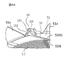
- FIG. 5 is an explanatory diagram in which a coil is arranged on the insulating bobbin of FIG. 4 and is a view seen from the winding part side.
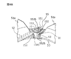
- FIG. 5 is an explanatory view in which a coil is arranged on the insulating bobbin of FIG. 4 and is a view seen from the outside.
- It is a schematic perspective view which shows the mode of the winding start lead wire of the insulation bobbin which wound the field winding, and has illustrated in the state which laid flat the insulation bobbin.
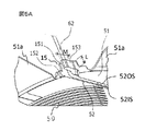
- Embodiment 2 of this invention is a principal part enlarged view corresponding to FIG.
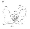
- FIG. 1 is a sectional view showing a rotor structure of a rotating electrical machine according to Embodiment 1 of the present invention
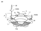
- FIG. 2 is a perspective view showing an insulating bobbin provided in the rotor of FIG. 1 and a field winding wound around the insulating bobbin.
- a rotor 1 of a rotating electrical machine includes a field winding 2 that generates magnetic flux and a first claw-shaped magnetic pole (claw pole) that is provided so as to cover the field winding 2 and is set so as to engage with each other.
- the field core 2 is composed of a field core body 3 and a second field core body 4, and the field winding 2 is wound around the winding portion 50 of the insulating bobbin 5.
- the slip ring assembly 7 is configured to supply current from the outside to the two slip rings via a brush (not shown).
- the terminal lead wire 61 after the field winding 2 is wound around the winding portion 50 of the insulating bobbin 5 is wound around the lead wire locking portion 14.
- the lead wire locking portion 14 is provided in a substantially T shape on the outer peripheral portion of the flange portion 51.
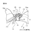
- the winding start lead wire 62 is stored in the winding start storage groove 52 provided on the inner surface of the flange portion 51, and then the patent document The lead wire is wound spirally by the rotation of the rotation shaft similar to that shown in FIG.
- the winding start storage groove 52 is provided as a concave opening groove extending from the intersection of the flange portion 51 and the winding portion 50 to the outer diameter end in the tangential direction.
- the free end portion of the winding start lead wire 62 stored in the winding start storing groove 52 is clamped and fixed by a clamping unit 15 described later.
- the lead wire 6 is pulled out from the lead wire locking portion 14 and the clamping portion 15 provided in the flange portion 51 of the insulating bobbin 5 and connected to the slip ring assembly 7.
- the second field core The trough-shaped magnetic poles 4P and 4P adjacent to each other on the body 4 extend from the valley 41 (FIG. 3) along the outer end surface to the terminals 8 and 9 constituting the slip ring assembly 7 via the lead wire connection point 10. It is connected.
- the clamping unit 15 includes a clamping groove 151 that is continuous with the winding start storage groove 52.
- An inner diameter side holding wall 152 is provided on the insulating bobbin central axis side of the holding groove 151, and an outer diameter side holding wall 153 is provided on the opposite side thereof.
- the outer diameter side surface 152S of the inner diameter side holding wall 152 is configured to be continuous and parallel to the inner diameter side wall surface 52IS of the winding start storing groove 52, and the inner diameter side surface 153S of the outer diameter side holding wall 153 is stored at the start of winding.
- the groove 52 is provided in a plane parallel to the outer diameter side wall surface 52OS.
- the outer diameter side wall surface 52OS of the winding start storage groove 52 is interrupted at the outer diameter edge of the flange 51, and does not hinder the storage of the winding start lead wire 62. As shown in FIGS.
- the winding start lead wire 62 stored in the winding start storage groove 52 extends in the groove direction (groove longitudinal direction) and is clamped from the inner diameter side wall surface 52IS of the winding start storage groove 52 to the inner diameter side. It is introduced into the holding groove 151 along the surface 152S on the outer diameter side of the wall 152. Thereafter, the winding start lead wire 62 is clamped in the clamping groove 151 and bent at a substantially right angle in the direction perpendicular to the direction of the winding start storage groove 52 and the X direction in the figure (direction parallel to the central axis of the insulating bobbin).
- the inner diameter side holding wall 152 is from the outer diameter end of the flange part 51. Without projecting to the outer diameter, it is within the range between the outer diameter end of the flange 51 and the valley 41 (see FIG. 3).
- the trough-opposing perimeter 152t of the inner diameter side clamping wall 152 has an offset shape along the trough portion 41.
- L is preferably about twice or more the conductor diameter D, and a desired clamping state after substantially right-angle bending can be maintained.
- the groove direction of the holding groove 151 is not the radial direction, but extends from the bottom surface of the winding portion 50 in a direction continuous with the winding start storage groove 52 provided in the tangential direction, and the inner diameter side holding wall 152 is a trough portion.
- the outer diameter side holding wall 153 can be configured such that the length extending from the outer diameter edge of the flange 51 is longer than the length of the inner diameter side holding wall 152 itself.
- the extending length M of the outer diameter side clamping wall 153 is composed of a clamping function part M1 adjacent to the clamping groove bottom 154 and a drop-off preventing part M2 integrated therewith. Also, it resists springback of almost right angle bending.
- the clamping function part M1 may be, for example, about 1.5 times the conductor diameter D, and the drop prevention part M2 that prevents the conductor (winding lead wire 62) from being released in the outer diameter direction is provided in the space of the valley 41. It is possible to configure.
- the outer surface in the X direction of the inner diameter side holding wall 152 and the outer diameter side holding wall 153 is a flat surface H, which defines the position of the insulating tube 16 in the flat placement shown in FIG.
- the insulating tube 16 is attached to a desired range P of the winding start lead wire 62, and insulates the field core body 4 in the post-process or in a state where the lead wire is connected to the connection portion. If there is no configuration with a flat surface H perpendicular to this axis, the insulating tube 16 is inclined and a part of the insulating tube 16 is displaced into the sandwiching portion 15 so that the range P cannot be secured, that is, the desired insulation is not performed. It does not hold as an electrical component.
- the holding portion of the insulating tube (insulating material) 16 The end surface on the 15th side is in contact with both the flat surface H of the inner diameter side holding wall 152 and the flat surface H of the outer diameter side holding wall 153. Accordingly, the insulating tube (insulating material) 16 through which the lead wire 62 is inserted is prevented from being inclined or displaced.
- a rotation preventing portion 53 is provided so as to protrude in the axial direction from above the flange portion 51.
- the anti-rotation part 53 provided on the inner diameter side of the sandwiching part 15 is fitted into the field core body on the inner diameter side of the valley 41 between the claw-shaped magnetic poles to prevent the insulating bobbin 5 from rotating from the field core.
- Insulation between the outer circumferential surface of the wound field winding 2 and the claw-shaped magnetic pole ⁇ claw-shaped magnetic pole 4P is performed by the cover portion 51a extending from the outer end surface of the flange portion 51.
- the end of the winding start lead wire 62 stored in the winding start storing groove 52 is not deformed by only a single right-angle bend without being damaged by multiple bendings and twists.
- the winding start lead wire 62 is securely held and prevented from falling off, and the field winding is wound from the insulated bobbin winding portion to the winding portion 50 (around the normal winding portion 50). Speeding up of the winding work).
- a complicated mechanism such as a winding facility in the case where the winding start lead wire 62 is locked to the substantially T-shaped neck portion is unnecessary, and the manufacturing cost can be reduced.
- a winding start in which a winding start outlet wire 62 of the field winding 2 is accommodated on the inner surface of the flange 51
- a storage groove 52 is provided, and the flange portion 51 is provided with a holding portion 15 located on the outer diameter side of the winding start storage groove 52, and the winding start storage groove is provided in the holding portion 15.
- 52 is located on an extension line of 52 and extends inclined with respect to the radial direction of the insulating bobbin.
- Holding grooves 151 are formed, the winding start opening out lines 62 of the field winding 2 is sandwiched by the sandwiching portions 15 is housed in the winding start receiving groove 52 and the holding grooves 151.
- a plurality of flange portions 51 of the flange portions 51, 51 provided on both sides in the axial direction of the winding portion 50 are formed in the circumferential direction of the insulating bobbin 5 with a predetermined space therebetween.
- the clamping portion 15 is located in the space.
- the sandwiching portion 15 is positioned corresponding to the valley 41 between the magnetic poles 4P and 4P of the field cores 3 and 4.
- the clamping groove 151 extends in the same direction as the winding start storage groove 52 and is continuous with the winding start storage groove 52.
- the clamping portion 15 includes an inner diameter side clamping wall 152, a clamping groove bottom 154, and an outer diameter side clamping wall 153.
- the clamping groove 151 includes an outer diameter side surface 152S of the inner diameter side clamping wall 152, and a clamping groove bottom.
- the holding groove bottom surface 154S of 154 and the inner surface 153S of the outer diameter side holding wall 153 are configured.
- the outer diameter side surface 152S of the inner diameter side holding wall 152 and the inner diameter side surface 153S of the outer diameter side holding wall 153 are parallel to each other. In other words, the inner diameter side surface 152S and the outer diameter side surface 153S of the sandwiching groove 151 itself are configured in parallel.
- An inner diameter side surface 153S of the outer diameter side holding wall 153 of the holding portion 15 is configured on the same plane as the outer diameter side wall surface (52OS) of the winding start storage groove 52.
- a trough facing portion 152t which is a facing portion of the inner diameter side sandwiching wall 152 of the sandwiching portion 15 with the field core trough 41, is configured along the field core trough.
- At least the outer diameter side clamping wall 153 of the clamping part 15 is provided with a deviation restraining part (flat surface) H that inhibits deviation of the winding start lead wire insulating material (insulating tube 16) integral with the clamping part 15. Yes.
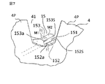
- Embodiment 2 For example, as another embodiment, a configuration in which the clamping function as shown in FIG. By providing at least one small protrusion 152a, 153a on the outer diameter side surface 152S of the inner diameter side holding wall 152 and the inner diameter side surface 153S of the outer diameter side holding wall 153, the winding start lead wire 62 is prevented from falling off. The effect can be enhanced. Further, as shown in the figure, when a plurality of windings are provided, a desired clamping state can be obtained by covering large and small winding diameter variations, and the insulating bobbin can be widely used or shared.
- the technical feature of the second embodiment is that the winding start outlet dropout restraining portions 152a and 153a that suppress the dropout of the winding start outlet wire on at least one of the inner diameter side holding wall and the outer diameter side holding wall.
- the winding start lead wire drop-off preventing portion is, for example, protrusions 152a and 153a.
- the number of poles of the rotor in each of the above embodiments, a configuration in which the sandwiching portion and the locking portion are provided only on one collar portion, and the like are not limited to the examples of the above embodiments, and other Implementation with various specifications is also possible.
Landscapes
- Engineering & Computer Science (AREA)
- Power Engineering (AREA)
- Insulation, Fastening Of Motor, Generator Windings (AREA)
- Synchronous Machinery (AREA)
Priority Applications (6)
| Application Number | Priority Date | Filing Date | Title |
|---|---|---|---|
| US16/303,227 US11038395B2 (en) | 2016-05-31 | 2016-05-31 | Rotor of rotary electrical machine |
| JP2018520237A JP6656366B2 (ja) | 2016-05-31 | 2016-05-31 | 回転電機の回転子 |
| MX2018014453A MX2018014453A (es) | 2016-05-31 | 2016-05-31 | Rotor de maquina electrica rotativa. |
| EP16903963.3A EP3468015B1 (en) | 2016-05-31 | 2016-05-31 | Rotor for rotary electric machine |
| CN201680086082.3A CN109314454B (zh) | 2016-05-31 | 2016-05-31 | 旋转电机的转子 |
| PCT/JP2016/065996 WO2017208335A1 (ja) | 2016-05-31 | 2016-05-31 | 回転電機の回転子 |
Applications Claiming Priority (1)
| Application Number | Priority Date | Filing Date | Title |
|---|---|---|---|
| PCT/JP2016/065996 WO2017208335A1 (ja) | 2016-05-31 | 2016-05-31 | 回転電機の回転子 |
Publications (1)
| Publication Number | Publication Date |
|---|---|
| WO2017208335A1 true WO2017208335A1 (ja) | 2017-12-07 |
Family
ID=60479452
Family Applications (1)
| Application Number | Title | Priority Date | Filing Date |
|---|---|---|---|
| PCT/JP2016/065996 WO2017208335A1 (ja) | 2016-05-31 | 2016-05-31 | 回転電機の回転子 |
Country Status (6)
| Country | Link |
|---|---|
| US (1) | US11038395B2 (zh) |
| EP (1) | EP3468015B1 (zh) |
| JP (1) | JP6656366B2 (zh) |
| CN (1) | CN109314454B (zh) |
| MX (1) | MX2018014453A (zh) |
| WO (1) | WO2017208335A1 (zh) |
Families Citing this family (1)
| Publication number | Priority date | Publication date | Assignee | Title |
|---|---|---|---|---|
| FR3131124A1 (fr) * | 2021-12-16 | 2023-06-23 | Valeo Equipements Electriques Moteur | Stator de machine électrique tournante équipé d’un isolant d’un bobinage d’excitation |
Citations (6)
| Publication number | Priority date | Publication date | Assignee | Title |
|---|---|---|---|---|
| US3603825A (en) * | 1970-05-21 | 1971-09-07 | Gen Motors Corp | Winding spool and lead support insulator for rotors of alternating current generators |
| JPS515913U (zh) * | 1974-06-29 | 1976-01-16 | ||
| JPH08331786A (ja) * | 1995-06-02 | 1996-12-13 | Nippondenso Co Ltd | 車両用コイル装置、および車両用交流発電機 |
| JP2000083337A (ja) * | 1998-09-04 | 2000-03-21 | Mitsubishi Electric Corp | 車両用交流発電機の回転子 |
| FR2818823A1 (fr) * | 2000-12-22 | 2002-06-28 | Valeo Equip Electr Moteur | Rotor de machine electrique tournante comportant un corps de bobine perfectionne et alternateur comportant un tel rotor |
| JP2015211525A (ja) * | 2014-04-25 | 2015-11-24 | 株式会社デンソー | 回転電機の回転子 |
Family Cites Families (11)
| Publication number | Priority date | Publication date | Assignee | Title |
|---|---|---|---|---|
| JPS52139950A (en) | 1976-05-17 | 1977-11-22 | Hitachi Ltd | Insulating bobbin for electrical machinery and apparatus |
| JPS62138041A (ja) * | 1985-12-11 | 1987-06-20 | Hitachi Ltd | 自動車用交流発電機 |
| JPS62135560U (zh) * | 1986-02-19 | 1987-08-26 | ||
| US5174013A (en) * | 1988-06-16 | 1992-12-29 | Nippondenso Co., Ltd. | Winding apparatus and method which deforms the wire during winding |
| US5886451A (en) * | 1997-10-30 | 1999-03-23 | Ford Motor Company | Wire routing design for a rotor of an electrical machine |
| JPH11273933A (ja) | 1998-03-20 | 1999-10-08 | Koyo Electronics Ind Co Ltd | コイル用のボビン及びその成形方法 |
| JP2000083336A (ja) * | 1998-09-04 | 2000-03-21 | Mitsubishi Electric Corp | 車両用交流発電機の回転子 |
| JP3185879B2 (ja) * | 1998-10-12 | 2001-07-11 | 株式会社デンソー | 車両用交流発電機の回転子 |
| US8225458B1 (en) * | 2001-07-13 | 2012-07-24 | Hoffberg Steven M | Intelligent door restraint |
| JP4860546B2 (ja) * | 2007-05-23 | 2012-01-25 | ミネベア株式会社 | コイルボビンおよびその製造方法 |
| JP4577386B2 (ja) * | 2008-03-19 | 2010-11-10 | 株式会社デンソー | 回転電機の回転子とその製造方法 |
-
2016
- 2016-05-31 JP JP2018520237A patent/JP6656366B2/ja active Active
- 2016-05-31 WO PCT/JP2016/065996 patent/WO2017208335A1/ja unknown
- 2016-05-31 MX MX2018014453A patent/MX2018014453A/es unknown
- 2016-05-31 EP EP16903963.3A patent/EP3468015B1/en active Active
- 2016-05-31 CN CN201680086082.3A patent/CN109314454B/zh active Active
- 2016-05-31 US US16/303,227 patent/US11038395B2/en active Active
Patent Citations (6)
| Publication number | Priority date | Publication date | Assignee | Title |
|---|---|---|---|---|
| US3603825A (en) * | 1970-05-21 | 1971-09-07 | Gen Motors Corp | Winding spool and lead support insulator for rotors of alternating current generators |
| JPS515913U (zh) * | 1974-06-29 | 1976-01-16 | ||
| JPH08331786A (ja) * | 1995-06-02 | 1996-12-13 | Nippondenso Co Ltd | 車両用コイル装置、および車両用交流発電機 |
| JP2000083337A (ja) * | 1998-09-04 | 2000-03-21 | Mitsubishi Electric Corp | 車両用交流発電機の回転子 |
| FR2818823A1 (fr) * | 2000-12-22 | 2002-06-28 | Valeo Equip Electr Moteur | Rotor de machine electrique tournante comportant un corps de bobine perfectionne et alternateur comportant un tel rotor |
| JP2015211525A (ja) * | 2014-04-25 | 2015-11-24 | 株式会社デンソー | 回転電機の回転子 |
Also Published As
| Publication number | Publication date |
|---|---|
| MX2018014453A (es) | 2019-03-28 |
| JP6656366B2 (ja) | 2020-03-04 |
| CN109314454B (zh) | 2021-06-15 |
| EP3468015B1 (en) | 2022-08-03 |
| EP3468015A1 (en) | 2019-04-10 |
| JPWO2017208335A1 (ja) | 2019-03-07 |
| CN109314454A (zh) | 2019-02-05 |
| US11038395B2 (en) | 2021-06-15 |
| EP3468015A4 (en) | 2019-11-06 |
| US20190207463A1 (en) | 2019-07-04 |
Similar Documents
| Publication | Publication Date | Title |
|---|---|---|
| EP2611000B1 (en) | Electric motor | |
| JP6580252B2 (ja) | 磁極、磁極の製造方法および固定子 | |
| CN103023167B (zh) | 电动机及电动机的制造方法 | |
| JP4106375B2 (ja) | 回転電機の固定子 | |
| US10439453B2 (en) | Stator | |
| JP5769828B2 (ja) | 回転電機のスリップリング装置 | |
| WO2015093157A1 (ja) | 回転電機 | |
| US11018543B2 (en) | Method for manufacturing stator of rotary electric machine including a cassette coil | |
| JP6341288B2 (ja) | ステータ組立方法及びステータ | |
| US20170353070A1 (en) | Stator assembly for motor | |
| US10128718B2 (en) | Stator, brushless motor, and stator manufacturing method | |
| US20140152128A1 (en) | Stator of rotary electric machine including restricting member for preventing deformation of coil end portions and electric motor including such stator | |
| WO2020174817A1 (ja) | 回転電機のステータ、回転電機、回転電機のステータの製造方法、および、回転電機の製造方法 | |
| TWI673936B (zh) | 軸向間隙型旋轉電機 | |
| KR20020086251A (ko) | 차량 교류 발전기용 회전자 | |
| JP5370245B2 (ja) | 回転電機の固定子の製造方法 | |
| WO2017208335A1 (ja) | 回転電機の回転子 | |
| JP2012105372A (ja) | 外転型の電動機 | |
| JP7081429B2 (ja) | モータ | |
| CN111682675A (zh) | 电子换向电机 | |
| JP6584473B2 (ja) | 燃料ポンプ及び燃料ポンプのステータコア巻線巻回方法 | |
| JP2013115974A (ja) | 回転電機のステータ | |
| US20230163651A1 (en) | Stator provided with insulating paper, motor having stator, and method for manufacturing motor | |
| CN113692689A (zh) | 用于电动转子绕组的端线的固持系统 | |
| CN113273063A (zh) | 旋转电机的定子和旋转电机的定子的制造方法 |
Legal Events
| Date | Code | Title | Description |
|---|---|---|---|
| ENP | Entry into the national phase |
Ref document number: 2018520237 Country of ref document: JP Kind code of ref document: A |
|
| NENP | Non-entry into the national phase |
Ref country code: DE |
|
| 121 | Ep: the epo has been informed by wipo that ep was designated in this application |
Ref document number: 16903963 Country of ref document: EP Kind code of ref document: A1 |
|
| ENP | Entry into the national phase |
Ref document number: 2016903963 Country of ref document: EP Effective date: 20190102 |