WO2017203737A1 - 圧電発電装置 - Google Patents
圧電発電装置 Download PDFInfo
- Publication number
- WO2017203737A1 WO2017203737A1 PCT/JP2017/000043 JP2017000043W WO2017203737A1 WO 2017203737 A1 WO2017203737 A1 WO 2017203737A1 JP 2017000043 W JP2017000043 W JP 2017000043W WO 2017203737 A1 WO2017203737 A1 WO 2017203737A1
- Authority
- WO
- WIPO (PCT)
- Prior art keywords
- power generation
- piezoelectric power
- pressing
- generation element
- piezoelectric
- Prior art date
- Legal status (The legal status is an assumption and is not a legal conclusion. Google has not performed a legal analysis and makes no representation as to the accuracy of the status listed.)
- Ceased
Links
Images




Classifications
-
- H—ELECTRICITY
- H02—GENERATION; CONVERSION OR DISTRIBUTION OF ELECTRIC POWER
- H02N—ELECTRIC MACHINES NOT OTHERWISE PROVIDED FOR
- H02N2/00—Electric machines in general using piezoelectric effect, electrostriction or magnetostriction
- H02N2/18—Electric machines in general using piezoelectric effect, electrostriction or magnetostriction producing electrical output from mechanical input, e.g. generators
-
- H—ELECTRICITY
- H10—SEMICONDUCTOR DEVICES; ELECTRIC SOLID-STATE DEVICES NOT OTHERWISE PROVIDED FOR
- H10N—ELECTRIC SOLID-STATE DEVICES NOT OTHERWISE PROVIDED FOR
- H10N30/00—Piezoelectric or electrostrictive devices
- H10N30/30—Piezoelectric or electrostrictive devices with mechanical input and electrical output, e.g. functioning as generators or sensors
-
- H—ELECTRICITY
- H10—SEMICONDUCTOR DEVICES; ELECTRIC SOLID-STATE DEVICES NOT OTHERWISE PROVIDED FOR
- H10N—ELECTRIC SOLID-STATE DEVICES NOT OTHERWISE PROVIDED FOR
- H10N30/00—Piezoelectric or electrostrictive devices
- H10N30/80—Constructional details
- H10N30/88—Mounts; Supports; Enclosures; Casings
Definitions
- the present invention relates to a piezoelectric power generation apparatus that extracts electric power by bending deformation caused by pressing a plate-shaped piezoelectric power generation element.
- An object of the present invention is to provide a piezoelectric power generator that requires a small load for pressing.
- a piezoelectric power generation device is a plate-like piezoelectric device that is housed in a case and has first and second main surfaces facing each other, and generates electric power by bending deformation when pressed.
- a power generation element, and first and second support portions supporting the piezoelectric power generation element, and a first pressing portion for pressing the piezoelectric power generation element are provided in the case,
- the first support portion and the first pressing portion are separated from each other in a first direction parallel to the main surface, and in the first direction, the first support portion and the first support portion are separated from each other.
- the second support part is arranged between the pressing part.
- the first and second support portions support the piezoelectric power generation element without being fixed to the first and second support portions.
- the piezoelectric power generation element in the first support portion, is not displaced in a direction opposite to the pressing direction, and the pressing force is applied to the second support portion.
- the piezoelectric power generation element is supported so that the piezoelectric power generation element is not displaced in the direction. In this case, the load required for pressing the piezoelectric power generation element can be reduced more effectively.
- the case includes a case body having an opening and a lid member fixed to the case body so as to cover the opening of the case body.
- the piezoelectric power generation element can be protected.
- a press part etc. can be easily provided using a cover material.
- a through hole is provided in the lid member at a portion where the first pressing portion is located, and the first inserted into the through hole.
- a pressing member is further provided. In this case, pressing can be easily performed by inserting the first pressing member into the through hole.
- the first pressing portion In still another specific aspect of the piezoelectric power generation device according to the present invention, in the second direction orthogonal to the first direction and parallel to the main surface of the piezoelectric power generation element, the first pressing portion Are provided, and a plurality of the first pressing portions are provided with through holes, and the first pressing member inserted into each through hole extends in the second direction. Is integrated. In this case, the plate-like piezoelectric power generation element can be bent more effectively.
- a second pressing portion for pressing the piezoelectric power generation element is provided in the first support portion.
- the piezoelectric power generation element can be deformed by pressing also in the second pressing portion.
- a through hole is formed in the lid member in the second pressing portion, and a second pressing member inserted into the through hole is provided. Furthermore, it is provided.
- the piezoelectric power generation element can be easily deformed simply by inserting and pressing the second pressing member into the through hole of the lid member.
- a plurality of the second pressing portions are provided in the second direction, and in each of the plurality of the second pressing portions, through holes are provided.
- the second pressing member provided in each through hole is integrated by a connecting member extending in the second direction. In this case, the plate-like piezoelectric power generation element can be more effectively deformed.
- the plate-shaped piezoelectric power generation element has a rectangular plate shape, and the first direction is a longitudinal direction of the rectangular plate shape. In this case, the load required for pressing can be further reduced.
- the piezoelectric power generation device since the stress applied to the piezoelectric power generation device does not change, the load necessary for pressing during power generation can be effectively reduced with the same amount of power generation as in the past. Therefore, the operability of the piezoelectric power generator is improved.
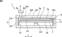
- FIG. 1 is a front cross-sectional view of a piezoelectric power generator according to a first embodiment of the present invention.
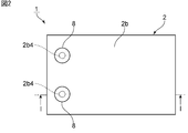
- FIG. 2 is a plan view of the piezoelectric power generation apparatus according to the first embodiment of the present invention.
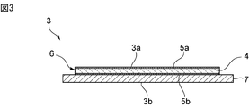
- FIG. 3 is a front sectional view showing the piezoelectric power generation element used in the piezoelectric power generation apparatus according to the first embodiment of the present invention.
- FIG. 4 is a schematic front view for explaining displacement due to pressing of the piezoelectric power generation element of the comparative example.
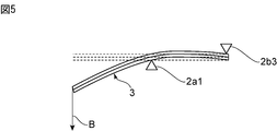
- FIG. 5 is a schematic front view for explaining displacement due to pressing of the piezoelectric power generating element in the first embodiment.
- FIG. 1 is a front cross-sectional view of a piezoelectric power generator according to a first embodiment of the present invention.
- FIG. 2 is a plan view of the piezoelectric power generation apparatus according to the first embodiment of the present invention.
- FIG. 3 is a front sectional view showing the piezoelectric power generation element used in the pie
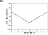
- FIG. 6 is a diagram showing the relationship between the longitudinal position of the piezoelectric power generation element and the stress on the surface of the piezoelectric body in the comparative example.
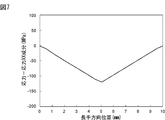
- FIG. 7 is a diagram illustrating the relationship between the longitudinal position of the piezoelectric power generation element and the stress on the surface of the piezoelectric body in the first embodiment.
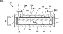
- FIG. 8 is a front sectional view of a piezoelectric power generating apparatus according to the second embodiment of the present invention.
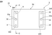
- FIG. 9 is a plan view of the piezoelectric power generation device according to the third embodiment.
- FIG. 10 is a front cross-sectional view of the piezoelectric power generating device according to the third embodiment.
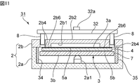
- FIG. 11 is a cross-sectional view taken along the line CC in FIG.
- FIG. 12 is a perspective view showing a state where the piezoelectric power generating element is bent and deformed in the third embodiment of the present invention.
- FIG. 13 is a perspective view for explaining a pressing member used in the third
- FIG. 1 is a front sectional view of a piezoelectric power generating apparatus according to a first embodiment of the present invention.
- the piezoelectric power generator 1 has a case 2.
- the case 2 includes a case main body 2a and a lid member 2b.
- the case body 2a has an opening whose upper surface is open.
- a lid member 2b is fixed to the case body 2a so as to cover the opening of the case body 2a.
- the case body 2a and the lid member 2b are made of an appropriate rigid material such as ceramics or metal.
- cover material 2b may be comprised by the resin film etc. which have a softness
- FIG. 3 is a front sectional view of the piezoelectric power generation element 3.
- the piezoelectric power generation element 3 has a piezoelectric body 4 such as PZT.
- An electrode 5 a is provided on one main surface of the piezoelectric body 4.
- An electrode 5 b is provided on the other main surface of the piezoelectric body 4.
- a rectangular piezoelectric element 6 is configured by the piezoelectric body 4 and the electrodes 5a and 5b.
- a metal plate 7 is joined to the rectangular plate-like piezoelectric element 6.
- the electrodes 5a and 5b are made of an appropriate metal material.
- the metal plate 7 is made of stainless steel or an appropriate metal or alloy.
- the metal plate 7 has elasticity.
- a piezoelectric element 6 is bonded to a metal plate 7 to form a unimorph type piezoelectric power generation element.
- the piezoelectric power generation element may be configured using a bimorph type piezoelectric element as well as a unimorph type.
- the piezoelectric power generation element 3 has a rectangular plate shape. A surface on the electrode 5a side of the piezoelectric power generation element 3 is defined as a first main surface 3a. The surface of the metal plate 7 opposite to the piezoelectric element 6 is the second main surface 3b. That is, the piezoelectric power generation element 3 has first and second main surfaces 3a and 3b facing each other.
- the piezoelectric power generation element 3 is a unimorph type piezoelectric power generation element as described above, for example, when it is bent and deformed in a rectangular plate shape, an electric charge is generated by the piezoelectric effect. Thereby, electric power can be taken out.
- the lid member 2b has a substantially rectangular plate shape.
- the outer peripheral portion protrudes toward the case body 2a. This protruding portion is joined to the upper end surface of the case body 2a.
- the longitudinal direction L of the piezoelectric power generation element 3 is the first direction in the present invention. That is, the longitudinal direction L, which is the first direction, is a direction parallel to the first and second main surfaces 3 a and 3 b of the piezoelectric power generation element 3. A direction perpendicular to the longitudinal direction L and parallel to the first and second main surfaces 3a and 3b of the piezoelectric power generating element 3 is a second direction. In the present embodiment, the second direction is the width direction in a substantially rectangular plate shape.
- the first support portion 2b3 is provided on one end side. The first support portion 2 b 3 protrudes toward the case body 2 a from the lower surface 2 b 1 and is in contact with the first main surface 3 a of the piezoelectric power generation element 3.
- the lid member 2b is provided with a first pressing portion 2b4 on the side opposite to the side where the first support portion 2b3 is provided in the longitudinal direction L of the piezoelectric power generating element 3.
- the 1st press part 2b4 has a through-hole which has penetrated the lower surface 2b1 from the upper surface 2b2 of the cover material 2b.
- a first pressing member 8 is inserted into the through hole.
- the first pressing member 8 includes an operation portion 8a having a bottom area larger than the diameter of the through hole, and a pressing portion 8b extending from the lower surface of the operation portion 8a into the through hole.
- the one end side of the piezoelectric power generating element 3 can be displaced downward by the pressing portion 8b.
- a second support part 2a1 is provided between the first pressing part 2b4 and the first support part 2b3.
- the second support portion 2a1 is provided so as to extend upward from the bottom surface of the case body 2a.
- the second support portion 2a1 has a hemispherical tip.
- tip of 2nd support part 2a1 may have shapes, such as a truncated cone and a truncated pyramid.
- the second support portion 2a1 may be a columnar shape or a prismatic shape.
- the second support portion 2a1 is preferably located at the center between the first support portion 2b3 and the first pressing portion 2b4.
- the second support portion 2a1 is in contact with the second main surface 3b. Therefore, in the piezoelectric generating element 3, the first support portion 2b3 and the first pressing portion 2b4 are located on the first main surface 3a side, and the second support surface is on the second main surface 3b side. The part 2a1 is located.
- guides 11 and 12 are provided on the case body 2a.
- the guides 11 and 12 are provided so as to protrude inward from the inner side surfaces facing each other in the longitudinal direction L. By providing the guides 11 and 12, undesired movement of the piezoelectric power generation element 3 in the longitudinal direction can be suppressed.
- the guides 11 and 12 are not necessarily provided.
- a guide may be provided on the inner surfaces facing each other in the width direction.
- the second support portion 2a1 is integrally formed of the same material as the case body 2a.
- the 2nd support part 2a1 may consist of a material different from the case main body 2a. In that case, it can be integrated by joining the second support portion 2a1 to the bottom surface of the case body 2a.
- the tip of the pressing portion 8b displaces the first main surface 3a of the piezoelectric power generating element 3 downward.
- the moving direction of the first pressing member 8 corresponds to the “pressing direction” of the present invention. Since the piezoelectric power generation element 3 is supported without being fixed to the first and second support portions 2b3 and 2a1, the piezoelectric power generation element 3 is in contact with the first support portion 2b3. Displacement in the direction opposite to the pressing direction is restricted. Moreover, in the part in which the 2nd support part 2a1 is provided, the displacement of the 2nd main surface 3b of the piezoelectric generating element 3 is controlled so that it may not displace further in a press direction.
- the piezoelectric power generating element 3 is bent and deformed as shown in FIG. As described in Patent Document 1, the load in this case is 1 ⁇ 2 compared to the case where the piezoelectric power generation element is supported by both ends. This will be described with reference to FIGS.
- FIG. 4 is a schematic front view for explaining displacement due to pressing of the piezoelectric power generation element of the comparative example.
- the piezoelectric power generation element 101 of the comparative example is supported at both ends, and a load is applied from above at the center in the longitudinal direction.
- a load is applied from above at the center in the longitudinal direction.
- the center part in the longitudinal direction is bent and deformed so as to protrude downward.
- the simulation results are shown below.
- a displacement amount at which a generated voltage of 50 V was obtained by applying a load A of 1 N to the center in the longitudinal direction was measured.
- a displacement of 34.8 ⁇ m was obtained from the reference point where no load was applied.
- the first support portion 2b3 in the longitudinal direction is supported by the first support portion 2b3 and the second support portion 2a1.
- the first pressing portion 2b4 on the opposite side to the above is pressed downward.
- the tip of the piezoelectric power generating element 3 is displaced downward.
- the simulation results are shown below. A displacement amount at which a generated voltage of 50 V was obtained by applying a load B of 0.5 N to the first pressing portion 2b4 was measured. As a result, a displacement of 69.6 ⁇ m was obtained from the reference point where no load was applied.
- FIG. 6 is a diagram showing the relationship between the longitudinal position of the piezoelectric power generation element 101 of the comparative example and the stress on the surface of the piezoelectric body, and FIG. It is a figure which shows the relationship with stress.
- the stress applied to each piezoelectric power generation element is almost the same, the same power generation voltage is obtained.
- the piezoelectric power generation element 3 of the present embodiment shown in FIGS. 5 and 7 has a lower spring constant. Therefore, even when a half load is applied, the maximum displacement can be doubled as compared with the comparative example.
- the maximum displacement amount is the displacement amount at the center in the longitudinal direction in the piezoelectric power generation element 101, and the displacement amount at one end side in the length direction in the piezoelectric power generation element 3.
- the piezoelectric power generation element 3 is supported by the first support portion 2b3 and the second support portion 2a1, and the first pressing portion 2b4, Since the second support portion 2a1 is provided between the first support portion 2b3 and the first support portion 2b3 as described above, it is possible to effectively reduce the load required for pressing with the same amount of power generation as that in the prior art. Can do.
- the cover member 2b is provided with a through hole and the first pressing portion 2b4 is provided.
- the present invention is not limited to the through hole.
- a thin portion that can be easily deformed by a finger or the like may be provided.
- the lid member 2b may be formed of a synthetic resin film that can be bent and deformed.
- FIG. 2 is a plan view of the piezoelectric generator 1.
- FIG. 1 shows a cross section of a portion along the line II in FIG.
- a plurality of first pressing portions 2b4 are provided in a second direction that is a width direction orthogonal to the first direction that is the longitudinal direction.
- the 1st press part 2b4 may be provided with two or more along the 2nd direction.
- first pressing members 8 and 8 are arranged in each first pressing portion 2b4.
- the first pressing members 8 and 8 may be pressed simultaneously or separately.
- a switch that is conducted when the first pressing member 8 is lowered by pressing may be provided in association with each first pressing member 8. Thereby, it can be detected which first pressing member 8 is lowered. Therefore, it is possible to detect which first pressing member 8 is pressed.
- FIG. 8 is a front cross-sectional view of a piezoelectric power generator according to a second embodiment of the present invention.
- the piezoelectric power generation device 21 includes a second pressing portion 2b5 and a second pressing member 22.
- the 2nd press part 2b5 is comprised by providing a through-hole in the 1st support part 2b3. This through hole is provided so as to reach from the upper surface 2b2 of the lid member 2b to the lower surface of the first support portion 2b3.
- a third support portion 2b6 is provided in a portion where the first pressing portion 2b4 is provided. Similar to the first support portion 2b3, the third support portion 2b6 protrudes from the lower surface 2b1 of the lid member 2b to the piezoelectric power generation element 3 side. The third support portion 2b6 is in contact with the first main surface 3a of the piezoelectric power generating element 3.
- the first pressing member 2b4 is pressed so as to lower the first pressing member 8, and the electric power can be taken out as in the case of the first embodiment.
- the second pressing portion 2b5 is provided also on the first support portion 2b3 side, the pressing operation is not performed on the first pressing portion 2b4, but the pressing operation is performed on the second pressing portion 2b5. You may go. In that case, the tip portion of the piezoelectric power generating element 3 on the second pressing portion 2b5 side is displaced downward. Accordingly, even if the second pressing member 22 is used instead of the first pressing member 8, electric power can be taken out.
- the piezoelectric power generating element 3 is restricted from being displaced in the direction opposite to the pressing direction in the third support portion 2b6. Further, at the center in the longitudinal direction, the piezoelectric power generating element 3 is restricted from being displaced in the pressing direction. Therefore, even when a pressing operation is performed using the second pressing portion 2b5, it is possible to effectively reduce the load required for pressing during power generation.
- FIG. 9 is a plan view of a piezoelectric power generating apparatus according to a third embodiment of the present invention
- FIG. 10 is a front sectional view
- FIG. 11 is a sectional view taken along the line CC in FIG.
- the piezoelectric power generation device 31 has the same structure as the piezoelectric power generation device 21.
- the first pressing members 8, 8 and the second pressing member along the second direction which is the width direction orthogonal to the first direction which is the longitudinal direction. 22 and 22 are provided.
- the plurality of first pressing members 8 arranged in the second direction are connected and integrated by a connecting member 32.
- the second pressing members 22, 22 are also connected and integrated by a connecting member 33.
- the connecting members 32 and 33 are extended in the second direction.
- the pressing operation part 32a which protrudes upward is provided in the center of the connection member 32.
- the connecting member 32 is pressed downward from above the pressing operation portion 32a, the first pressing members 8, 8 are lowered.
- a pressing operation portion 33a is provided on the connecting member 33.
- the press operation parts 32a and 33a do not need to be provided, when the press operation parts 32a and 33a are provided, a press operation can be performed easily.
- the pressing operation parts 32a and 33a are provided in the center of the connection members 32 and 33 in the second direction. Therefore, the first and second pressing members 8, 8, 22, 22 on both sides can be lowered evenly and easily.
- Guides 34 and 35 are provided on the inner surface of the case facing each other in the width direction.
- the piezoelectric power generation device 31 is configured in the same manner as the piezoelectric power generation device 21 except for the above points. As in the present embodiment, in the second direction, a plurality of pressure members that are distributed may be connected and integrated by a connecting member.
- FIG. 12 is a perspective view showing a state where the piezoelectric power generating element 3 is bent and deformed by pressing downward from the pressing operation portion 32a of the piezoelectric power generating device 31.
- FIG. 12 As shown in the drawing, the piezoelectric power generation element 3 having a rectangular plate shape is bent and deformed so that one end in the longitudinal direction is displaced downward. Thereby, an electric charge can be generated.
Landscapes
- General Electrical Machinery Utilizing Piezoelectricity, Electrostriction Or Magnetostriction (AREA)
Abstract
押圧に必要な荷重を小さくし得る、圧電発電装置を提供する。 ケース2内に板状の圧電発電素子3が収納されている、圧電発電装置1。圧電発電素子3を支持している第1の支持部2b3と、第2の支持部2a1と、圧電発電素子3を押圧するための第1の押圧部2b4とがケース2に設けられている。第1の支持部2b3及び第1の押圧部2b4が、圧電発電素子3の第1の主面3a側に配置されており、第2の支持部2a1が、第2の主面3b側に配置されている。圧電発電素子3の第1,第2の主面3a,3bに平行な第1の方向において、第1の支持部2b3と、第1の押圧部2b4とが隔てられており、第1の方向において、第1の支持部2b3と、第1の押圧部2b4との間に、第2の支持部2a1が配置されている。
Description
本発明は、板状の圧電発電素子の押圧による屈曲変形により電力を取り出す、圧電発電装置に関する。
従来、板状の圧電発電素子を用いた圧電発電装置が種々提案されている。下記の特許文献1に記載の圧電発電装置では、矩形板状の圧電発電素子が、ケース内において支持されている。圧電発電素子の両端近傍が、ケースに設けられた支持台により支持されている。この圧電発電装置では、両持ちで圧電発電素子が支持されており、一対の支持台間の中央において圧電発電素子が上方から押圧される。
特許文献1に記載の圧電発電装置では、圧電発電素子を屈曲させるのに必要な荷重が大きかった。そのため、操作性が十分でなかった。
本発明の目的は、押圧に必要な荷重が小さい、圧電発電装置を提供することにある。
本発明に係る圧電発電装置は、ケースと、前記ケース内に収納されており、対向し合う第1,第2の主面を有し、押圧された際の屈曲変形により発電する板状の圧電発電素子とを備え、前記圧電発電素子を支持している第1,第2の支持部と、前記圧電発電素子を押圧するための第1の押圧部とが、前記ケースに設けられており、前記第1の支持部及び前記第1の押圧部が前記第1の主面側に、前記第2の支持部が前記第2の主面側に配置されており、前記板状の圧電発電素子の主面に平行な第1の方向において、前記第1の支持部と、前記第1の押圧部とが隔てられており、前記第1の方向において、前記第1の支持部と前記第1の押圧部との間に、前記第2の支持部が配置されている。
本発明に係る圧電発電装置のある特定の局面では、前記第1及び第2の支持部において、前記圧電発電素子が前記第1,第2の支持部に固定されることなく、支持されている。
本発明に係る圧電発電装置の他の特定の局面では、前記第1の支持部において、押圧方向と反対方向に前記圧電発電素子が変位しないように、かつ、前記第2の支持部において前記押圧方向に前記圧電発電素子が変位しないように、前記圧電発電素子が支持されている。この場合には、圧電発電素子の押圧に必要な荷重をより効果的に小さくすることができる。
本発明に係る圧電発電装置の別の特定の局面では、前記ケースが、開口を有するケース本体と、前記ケース本体の前記開口を覆うように前記ケース本体に固定されている蓋材とを有する。この場合には、圧電発電素子を保護することができる。また、蓋材を利用して、押圧部等を容易に設けることができる。
本発明に係る圧電発電装置のさらに他の特定の局面では、前記第1の押圧部が位置する部分において前記蓋材に貫通孔が設けられており、該貫通孔内に挿入される第1の押圧部材がさらに備えられている。この場合には、第1の押圧部材を貫通孔に挿入するようにして、押圧を容易に行うことができる。
本発明に係る圧電発電装置のさらに他の特定の局面では、前記第1の方向と直交し、かつ前記圧電発電素子の前記主面に平行である第2の方向において、前記第1の押圧部が複数設けられており、複数の前記第1の押圧部において、それぞれ貫通孔が設けられており、各貫通孔に挿入されている前記第1の押圧部材が前記第2の方向に延びる連結部材により一体化されている。この場合には、板状の圧電発電素子を、より一層効果的に屈曲させることができる。
本発明に係る圧電発電装置のさらに他の特定の局面では、前記第1の支持部内において、前記圧電発電素子を押圧するための第2の押圧部が設けられている。この場合には、第2の押圧部においても、押圧により圧電発電素子を変形させることができる。
本発明に係る圧電発電装置のさらに他の特定の局面では、前記第2の押圧部において、前記蓋材に貫通孔が形成されており、該貫通孔内に挿入される第2の押圧部材がさらに備えられている。この場合には、蓋材の貫通孔内に第2の押圧部材を挿入し、押圧するだけで、圧電発電素子を容易に変形させることができる。
本発明に係る圧電発電装置のさらに他の特定の局面では、前記第2の方向において、前記第2の押圧部が複数設けられており、複数の前記第2の押圧部において、それぞれ貫通孔が設けられており、各貫通孔に挿入されている前記第2の押圧部材が前記第2の方向に延びる連結部材により一体化されている。この場合には、板状の圧電発電素子をより効果的に変形させることができる。
本発明に係る圧電発電装置のさらに他の特定の局面では、前記板状の圧電発電素子が矩形板状の形状を有し、前記第1の方向が矩形板状の形状の長手方向である。この場合には、押圧に必要な荷重をより一層小さくすることができる。
本発明に係る圧電発電装置によれば、圧電発電装置に与える応力が変わらないので、従来と同一の発電量で、発電に際しての押圧に必要な荷重を効果的に小さくすることができる。従って、圧電発電装置の操作性が高められる。
以下、図面を参照しつつ、本発明の具体的な実施形態を説明することにより、本発明を明らかにする。
なお、本明細書に記載の各実施形態は、例示的なものであり、異なる実施形態間において、構成の部分的な置換または組み合わせが可能であることを指摘しておく。また、文中の「上」「下」は図面の上下を指す。
図1は、本発明の第1の実施形態に係る圧電発電装置の正面断面図である。圧電発電装置1は、ケース2を有する。ケース2は、ケース本体2aと、蓋材2bとを有する。ケース本体2aは、上方の一面が開いた開口を有する。ケース本体2aの開口を覆うように、蓋材2bが、ケース本体2aに固定されている。
ケース本体2a及び蓋材2bは、例えばセラミックスや金属などの適宜の剛性材料からなる。もっとも、蓋材2bは、柔軟性を有する樹脂フィルムなどにより構成されていてもよい。
ケース2内に、板状の圧電発電素子3が収納されている。図3は、圧電発電素子3の正面断面図である。圧電発電素子3は、PZTなどの圧電体4を有する。圧電体4の一方主面に電極5aが設けられている。圧電体4の他方主面に電極5bが設けられている。圧電体4及び電極5a,5bにより矩形の圧電素子6が構成されている。この矩形板状の圧電素子6に、金属板7が接合されている。電極5a,5bは、適宜の金属材料からなる。金属板7は、ステンレスや、適宜の金属もしくは合金からなる。金属板7は、弾性を有する。金属板7に圧電素子6が貼り合わされて、ユニモルフ型の圧電発電素子が構成されている。なお、ユニモルフ型に限らず、バイモルフ型の圧電素子を用いて圧電発電素子が構成されていてもよい。
圧電発電素子3は矩形板状の形状を有する。圧電発電素子3の電極5a側の面を第1の主面3aとする。金属板7の圧電素子6とは反対側の面が第2の主面3bとなる。すなわち、圧電発電素子3は、対向し合う第1,第2の主面3a,3bを有する。
圧電発電素子3は、上記のようにユニモルフ型の圧電発電素子であるため、例えば矩形板状の形状において、屈曲変形すると、圧電効果により電荷を発生させる。それによって、電力を取り出すことができる。
図1に戻り、蓋材2bは、略矩形板状の形状を有する。この蓋材2bの下面2b1において、外周部が、ケース本体2a側に突出している。この突出している部分が、ケース本体2aの上端面に接合されている。
本実施形態では、圧電発電素子3の長手方向Lが、本発明における第1の方向である。すなわち、第1の方向である長手方向Lは、圧電発電素子3の第1,第2の主面3a,3bに平行な方向である。この長手方向Lと直交する方向であって、圧電発電素子3の第1,第2の主面3a,3bに平行な方向が第2の方向である。本実施形態では、第2の方向は、略矩形板状の形状における幅方向である。上記長手方向Lにおいて、一端側に、第1の支持部2b3が設けられている。第1の支持部2b3は、下面2b1よりもケース本体2a側に突出しており、圧電発電素子3の第1の主面3aに当接されている。
蓋材2bには、圧電発電素子3の長手方向Lにおいて、第1の支持部2b3が設けられている側とは反対側に第1の押圧部2b4が設けられている。第1の押圧部2b4は、蓋材2bの上面2b2から下面2b1を貫いている貫通孔を有する。この貫通孔内に、第1の押圧部材8が挿入されている。第1の押圧部材8は、上記貫通孔の径よりも大きな底面積を有する操作部8aと、操作部8aの下面から貫通孔内に延びる押圧部8bとを有する。
第1の押圧部材8を図示の状態から下方に移動させることにより、押圧部8bにより、圧電発電素子3の一端側を下方に変位させることができる。
ところで、上記第1の押圧部2b4と、第1の支持部2b3との間に、第2の支持部2a1が設けられている。第2の支持部2a1は、ケース本体2aの底面から上方に延びるように設けられている。第2の支持部2a1は、その先端が半球状とされている。もっとも、第2の支持部2a1の先端は、円錐台や角錐台などの形状を有していてもよい。また、第2の支持部2a1は、円柱状や角柱状であってもよい。
好ましくは、第2の支持部2a1は、第1の支持部2b3と、第1の押圧部2b4との間の中央に位置していることが望ましい。
第2の支持部2a1は、第2の主面3bに当接されている。従って、圧電発電素子3では、第1の主面3a側に、第1の支持部2b3と、第1の押圧部2b4とが位置しており、第2の主面3b側に第2の支持部2a1が位置している。
なお、ケース本体2aには、ガイド11,12が設けられている。ガイド11,12は、長手方向Lにおいて対向し合う内側面から、内側に突出するように設けられている。ガイド11,12を設けることにより、圧電発電素子3の長手方向への所望でない移動を抑制することができる。もっとも、ガイド11,12は必ずしも設けられずともよい。
また、幅方向における圧電発電素子の位置ずれを防止するために、同様に、幅方向において対向し合う内側面にガイドを設けてもよい。
また、上記第2の支持部2a1は、ケース本体2aと同じ材料で一体で構成されている。もっとも、第2の支持部2a1は、ケース本体2aと異なる材料からなるものであってもよい。その場合には、第2の支持部2a1を、ケース本体2aの底面に接合することにより、一体化され得る。
発電に際しては、第1の押圧部材8を下方に移動させるように荷重を加えると、押圧部8bの先端が、圧電発電素子3の第1の主面3aを下方に変位させる。第1の押圧部材8の移動方向が本願発明の「押圧方向」に相当する。圧電発電素子3が前記第1,第2の支持部2b3,2a1に固定されることなく、支持されているため、圧電発電素子3は、第1の支持部2b3と接触している部分では、押圧方向と逆方向への変位が規制される。また、第2の支持部2a1が設けられている部分においては、圧電発電素子3の第2の主面3bは、押圧方向にそれ以上変位しないように変位が規制される。そのため、圧電発電素子3は、図5に示すように屈曲変形する。この場合の荷重は、特許文献1に記載のように、圧電発電素子が両持ちで支持されている場合に比べて1/2となる。これを、図4~図8を参照して説明する。
図4は、比較例の圧電発電素子の押圧による変位を説明するための略図的正面図である。比較例の圧電発電素子101では、両端で支持されており、長手方向中央において上方から荷重を加える。その結果、矢印Aで示すように、長手方向中央部が下方に突出するように屈曲変形する。以下にシミュレーションの結果を示す。長手方向中央に1Nの荷重Aを加えて50Vの発電電圧が得られる変位量を測定した。その結果、荷重を加えていない状態である基準点から34.8μmの変位が得られた。
他方、図5に示すように、本実施形態の圧電発電素子3では、第1の支持部2b3と、第2の支持部2a1とで支持されているため、長手方向において第1の支持部2b3とは反対側の、前述した第1の押圧部2b4において、下方に向かって押圧される。その結果、矢印Bで示すように、圧電発電素子3の先端が下方に変位する。以下にシミュレーションの結果を示す。第1の押圧部2b4に0.5Nの荷重Bを加えて50Vの発電電圧が得られる変位量を測定した。その結果、荷重を加えていない状態である基準点から69.6μmの変位が得られた。
図6は、上記比較例の圧電発電素子101における長手方向位置と、圧電体表面の応力との関係を示す図であり、図7は、圧電発電素子3における長手方向位置と、圧電体表面の応力との関係を示す図である。本実施形態と比較例では、それぞれの圧電発電素子に与えられる応力がほとんど同一であるので、同一の発電電圧が得られている。
図4及び図6に示す圧電発電素子101の場合に比べ、図5及び図7に示す本実施形態の圧電発電素子3では、バネ定数が低くなる。そのため、1/2の荷重を加えた場合であっても、最大変位量を比較例の場合の2倍とすることができる。ここで、最大変位量とは、圧電発電素子101では、長手方向中央における変位量となり、圧電発電素子3では、長さ方向一端側における変位量となる。
上記のように、第1の実施形態に係る圧電発電装置1では、圧電発電素子3が、第1の支持部2b3と第2の支持部2a1とで支持され、第1の押圧部2b4と、第1の支持部2b3との間に第2の支持部2a1が上記のように設けられているため、発電に際し、従来と同一の発電量で、押圧に必要な荷重を効果的に小さくすることができる。
圧電発電素子3では、上記第1の押圧部材8により、圧電発電素子3を押圧する操作が繰り返されることにより、圧電効果により生じた電荷に基づき、電力を取り出すことができる。
なお、上記実施形態では、蓋材2bに貫通孔を設け、第1の押圧部2b4を設けていたが、貫通孔に限らず、例えば蓋材2bにおいて、第1の押圧部2b4を構成する部分において、指等によって容易に変形し得るような薄肉部を設けてもよい。このような場合、蓋材2bを、屈曲変形し得る合成樹脂フィルムにより構成すればよい。
なお、図2は、圧電発電装置1の平面図である。図1では、図2のI-I線に沿う部分の断面が示されている。図2に示すように、長手方向である第1の方向と直交する幅方向である第2の方向において、複数の第1の押圧部2b4が設けられている。このように、第1の押圧部2b4は、第2の方向に沿って複数設けられていてもよい。なお、各第1の押圧部2b4において、第1の押圧部材8,8が配置されている。
押圧操作に際しては、第1の押圧部材8,8を同時に押圧してもよく、別々に押圧してもよい。
その場合、第1の押圧部材8が押圧により降下した場合に、導通されるスイッチを各第1の押圧部材8に関連して設けてもよい。それによって、いずれの第1の押圧部材8が降下しているかを検出することができる。よって、いずれの第1の押圧部材8が押圧されているかを検出することも可能となる。
図8は、本発明の第2の実施形態に係る圧電発電装置の正面断面図である。
圧電発電装置21は、第2の押圧部2b5及び第2の押圧部材22を有する。第2の押圧部2b5は、第1の支持部2b3内において、貫通孔を設けることにより構成されている。この貫通孔は、蓋材2bの上面2b2から第1の支持部2b3の下面に至るように設けられている。
さらに、第1の押圧部2b4が設けられている部分において、第3の支持部2b6が設けられている。第3の支持部2b6は、第1の支持部2b3と同様に、蓋材2bの下面2b1から圧電発電素子3側に突出している。そして、第3の支持部2b6は、圧電発電素子3の第1の主面3aに当接されている。
その他の構成は圧電発電装置21は、圧電発電装置1と同様であるため、同一部分については同一の参照番号を付することにより、その説明を省略する。
圧電発電装置21では、第1の押圧部2b4において第1の押圧部材8を降下するように押圧して、第1の実施形態の場合と同様に電力を取り出すことができる。加えて、第1の支持部2b3側においても、第2の押圧部2b5が設けられているので、第1の押圧部2b4において押圧操作を行わずに、第2の押圧部2b5において押圧操作を行ってもよい。その場合には、第2の押圧部2b5側における圧電発電素子3の先端部分が下方に変位されることになる。従って、第1の押圧部材8ではなく、第2の押圧部材22を用いても、電力を取り出すことができる。
第2の押圧部材22を用いて押圧操作を繰り返す場合においても、圧電発電素子3は、第3の支持部2b6においては、押圧方向と逆方向への変位が規制されている。また、長手方向中央においては、圧電発電素子3は、押圧方向への変位が規制されている。従って、第2の押圧部2b5を用いて押圧操作を行った場合においても、発電に際して押圧に必要な荷重を効果的に小さくすることができる。
図9は本発明の第3の実施形態に係る圧電発電装置の平面図であり、図10は正面断面図であり、図11は図9中のC-C線に沿う断面図である。
図10に示すように、圧電発電装置31は、圧電発電装置21と同様の構造を有する。もっとも、図9及び図11に示すように、長手方向である第1の方向と直交する幅方向である第2の方向に沿って、上記第1の押圧部材8,8及び第2の押圧部材22,22が設けられている。そして、第2の方向において配置されている複数の第1の押圧部材8同士が、連結部材32により連結され一体化されている。同様に、第2の押圧部材22,22も連結部材33により連結され一体化されている。連結部材32,33は、図9に示すように、第2の方向に延ばされている。また、連結部材32の中央には、図13に示すように、上方に突出している押圧操作部32aが設けられている。押圧操作部32aの上から連結部材32が下方に押圧されることにより、第1の押圧部材8,8が降下する。
連結部材33上にも、押圧操作部33aが設けられている。なお、押圧操作部32a,33aは設けられずともよいが、押圧操作部32a,33aが設けられている場合、押圧操作を容易に行うことができる。また、押圧操作部32a,33aは、第2の方向において、連結部材32,33の中央に設けられている。従って、両側の第1,第2の押圧部材8,8,22,22を均等に容易に降下させることができる。
ガイド34,35が、幅方向において対向しているケース内側面に設けられている。
圧電発電装置31は、上記の点を除けば、圧電発電装置21と同様に構成されている。本実施形態のように、第2の方向において、分散配置されている複数の押圧部材を、連結部材により連結し一体化してもよい。
図12は、圧電発電装置31の押圧操作部32aから下方に押圧することにより、圧電発電素子3が屈曲変形した状態を示す斜視図である。図示のように、矩形板状の圧電発電素子3が、長手方向一端側が下方に変位するように屈曲変形する。それによって、電荷を発生させることができる。
1…圧電発電装置
2…ケース
2a…ケース本体
2a1…第2の支持部
2b…蓋材
2b1…下面
2b2…上面
2b3…第1の支持部
2b4…第1の押圧部
2b5…第2の押圧部
2b6…第3の支持部
3…圧電発電素子
3a…第1の主面
3b…第2の主面
4…圧電体
5a,5b…電極
6…圧電素子
7…金属板
8…第1の押圧部材
8a…操作部
8b…押圧部
11,12…ガイド
21…圧電発電装置
22…第2の押圧部材
31…圧電発電装置
32a,33a…押圧操作部
32,33…連結部材
34,35…ガイド
2…ケース
2a…ケース本体
2a1…第2の支持部
2b…蓋材
2b1…下面
2b2…上面
2b3…第1の支持部
2b4…第1の押圧部
2b5…第2の押圧部
2b6…第3の支持部
3…圧電発電素子
3a…第1の主面
3b…第2の主面
4…圧電体
5a,5b…電極
6…圧電素子
7…金属板
8…第1の押圧部材
8a…操作部
8b…押圧部
11,12…ガイド
21…圧電発電装置
22…第2の押圧部材
31…圧電発電装置
32a,33a…押圧操作部
32,33…連結部材
34,35…ガイド
Claims (10)
- ケースと、
前記ケース内に収納されており、対向し合う第1,第2の主面を有し、押圧された際の屈曲変形により発電する板状の圧電発電素子とを備え、
前記圧電発電素子を支持している第1,第2の支持部と、前記圧電発電素子を押圧するための第1の押圧部とが、前記ケースに設けられており、前記第1の支持部及び前記第1の押圧部が前記第1の主面側に、前記第2の支持部が前記第2の主面側に配置されており、
前記板状の圧電発電素子の主面に平行な第1の方向において、前記第1の支持部と、前記第1の押圧部とが隔てられており、前記第1の方向において、前記第1の支持部と前記第1の押圧部との間に、前記第2の支持部が配置されている、圧電発電装置。 - 前記第1及び第2の支持部において、前記圧電発電素子が前記第1,第2の支持部に固定されることなく、支持されている、請求項1に記載の圧電発電装置。
- 前記第1の支持部において、押圧方向と反対方向に前記圧電発電素子が変位しないように、かつ、前記第2の支持部において前記押圧方向に前記圧電発電素子が変位しないように、前記圧電発電素子が支持されている、請求項2に記載の圧電発電装置。
- 前記ケースが、開口を有するケース本体と、前記ケース本体の前記開口を覆うように前記ケース本体に固定されている蓋材とを有する、請求項1~3のいずれか1項に記載の圧電発電装置。
- 前記第1の押圧部が位置する部分において前記蓋材に貫通孔が設けられており、該貫通孔内に挿入される第1の押圧部材をさらに備える、請求項1~4のいずれか1項に記載の圧電発電装置。
- 前記第1の方向と直交し、かつ前記圧電発電素子の前記主面に平行である第2の方向において、前記第1の押圧部が複数設けられており、複数の前記第1の押圧部において、それぞれ貫通孔が設けられており、各貫通孔に挿入されている前記第1の押圧部材が前記第2の方向に延びる連結部材により一体化されている、請求項5に記載の圧電発電装置。
- 前記第1の支持部内において、前記圧電発電素子を押圧するための第2の押圧部が設けられている、請求項4に記載の圧電発電装置。
- 前記第2の押圧部において、前記蓋材に貫通孔が形成されており、該貫通孔内に挿入される第2の押圧部材をさらに備える、請求項7に記載の圧電発電装置。
- 前記第2の方向において、前記第2の押圧部が複数設けられており、複数の前記第2の押圧部において、それぞれ貫通孔が設けられており、各貫通孔に挿入されている前記第2の押圧部材が前記第2の方向に延びる連結部材により一体化されている、請求項8に記載の圧電発電装置。
- 前記板状の圧電発電素子が矩形板状の形状を有し、前記第1の方向が矩形板状の形状の長手方向である、請求項1~9のいずれか1項に記載の圧電発電装置。
Applications Claiming Priority (2)
| Application Number | Priority Date | Filing Date | Title |
|---|---|---|---|
| JP2016-105730 | 2016-05-27 | ||
| JP2016105730 | 2016-05-27 |
Publications (1)
| Publication Number | Publication Date |
|---|---|
| WO2017203737A1 true WO2017203737A1 (ja) | 2017-11-30 |
Family
ID=60411208
Family Applications (1)
| Application Number | Title | Priority Date | Filing Date |
|---|---|---|---|
| PCT/JP2017/000043 Ceased WO2017203737A1 (ja) | 2016-05-27 | 2017-01-04 | 圧電発電装置 |
Country Status (1)
| Country | Link |
|---|---|
| WO (1) | WO2017203737A1 (ja) |
Citations (3)
| Publication number | Priority date | Publication date | Assignee | Title |
|---|---|---|---|---|
| JP2004282978A (ja) * | 2003-03-12 | 2004-10-07 | Seratekku:Kk | 携帯発電機 |
| JP2013500695A (ja) * | 2009-07-27 | 2013-01-07 | シーメンス アクチエンゲゼルシヤフト | 圧電曲がり素子を変形させる曲げ装置、同曲げ装置を用いて機械的エネルギーを電気エネルギーに変換する圧電エネルギー変換器、及び機械的エネルギーを電気エネルギーに変換する方法 |
| JP2015220872A (ja) * | 2014-05-18 | 2015-12-07 | 俊樹 小野 | 電力発電装置、情報入力装置、並びに情報入力機器保護装置 |
-
2017
- 2017-01-04 WO PCT/JP2017/000043 patent/WO2017203737A1/ja not_active Ceased
Patent Citations (3)
| Publication number | Priority date | Publication date | Assignee | Title |
|---|---|---|---|---|
| JP2004282978A (ja) * | 2003-03-12 | 2004-10-07 | Seratekku:Kk | 携帯発電機 |
| JP2013500695A (ja) * | 2009-07-27 | 2013-01-07 | シーメンス アクチエンゲゼルシヤフト | 圧電曲がり素子を変形させる曲げ装置、同曲げ装置を用いて機械的エネルギーを電気エネルギーに変換する圧電エネルギー変換器、及び機械的エネルギーを電気エネルギーに変換する方法 |
| JP2015220872A (ja) * | 2014-05-18 | 2015-12-07 | 俊樹 小野 | 電力発電装置、情報入力装置、並びに情報入力機器保護装置 |
Similar Documents
| Publication | Publication Date | Title |
|---|---|---|
| JP4802313B2 (ja) | 圧電振動子の保持装置 | |
| TW201820766A (zh) | 裝置、傳遞觸覺回饋及具裝置之組件 | |
| US8450909B2 (en) | Piezoelectric power generating apparatus | |
| EP2485287A3 (en) | Bistable piezoelectric generator | |
| US7732975B1 (en) | Biased gap-closing actuator | |
| WO2018235658A1 (ja) | 誘電エラストマートランスデューサーおよび誘電エラストマー駆動装置 | |
| WO2017203737A1 (ja) | 圧電発電装置 | |
| KR101094470B1 (ko) | 압전 발전기 | |
| JP2019041217A (ja) | 振動デバイス及び音響デバイス | |
| JP6489237B2 (ja) | 圧電発電装置 | |
| JP2022007045A (ja) | 誘電エラストマートランスデューサー | |
| JP2018186656A5 (ja) | ||
| KR101935672B1 (ko) | 전기활성 물질 및 형상기억소재를 이용한 에너지 하베스팅 장치 | |
| US20150061462A1 (en) | Vibration producing device as well as electronic device and human body fitting article both employing such vibration producing device | |
| JP5346684B2 (ja) | 圧電発電ユニット | |
| JP2016095255A (ja) | プローブ及びプローブカード | |
| JPWO2010032826A1 (ja) | 振動型アクチュエータの支持装置 | |
| KR20150127460A (ko) | 전기발생장치 | |
| TWI566511B (zh) | 壓電發電器 | |
| JP2018105785A (ja) | 電気接触子及び電気部品用ソケット | |
| KR102769709B1 (ko) | 웨이비 배선을 이용한 압전소자 발전 시스템 | |
| JP7207146B2 (ja) | 振動デバイス及び電子機器 | |
| JP4967019B2 (ja) | 電歪アクチュエータ | |
| WO2019235301A1 (ja) | フレキシブル基板、圧電素子ユニット及び触覚呈示装置 | |
| KR101942688B1 (ko) | 전기활성 물질을 이용한 다중 포인트 자극 타입 에너지 하베스팅 장치 |
Legal Events
| Date | Code | Title | Description |
|---|---|---|---|
| NENP | Non-entry into the national phase |
Ref country code: DE |
|
| 121 | Ep: the epo has been informed by wipo that ep was designated in this application |
Ref document number: 17802339 Country of ref document: EP Kind code of ref document: A1 |
|
| 122 | Ep: pct application non-entry in european phase |
Ref document number: 17802339 Country of ref document: EP Kind code of ref document: A1 |
|
| NENP | Non-entry into the national phase |
Ref country code: JP |