WO2017203585A1 - 補正値取得装置、画像処理装置、光走査型観察システム、補正値取得方法および画像処理方法 - Google Patents
補正値取得装置、画像処理装置、光走査型観察システム、補正値取得方法および画像処理方法 Download PDFInfo
- Publication number
- WO2017203585A1 WO2017203585A1 PCT/JP2016/065225 JP2016065225W WO2017203585A1 WO 2017203585 A1 WO2017203585 A1 WO 2017203585A1 JP 2016065225 W JP2016065225 W JP 2016065225W WO 2017203585 A1 WO2017203585 A1 WO 2017203585A1
- Authority
- WO
- WIPO (PCT)
- Prior art keywords
- irradiation position
- correction value
- theoretical
- illumination light
- observation
- Prior art date
Links
Images


Classifications
-
- A—HUMAN NECESSITIES
- A61—MEDICAL OR VETERINARY SCIENCE; HYGIENE
- A61B—DIAGNOSIS; SURGERY; IDENTIFICATION
- A61B1/00—Instruments for performing medical examinations of the interior of cavities or tubes of the body by visual or photographical inspection, e.g. endoscopes; Illuminating arrangements therefor
Definitions
- the present invention relates to a correction value acquisition device, an image processing device, an optical scanning observation system, a correction value acquisition method, and an image processing method.
- an optical scanning observation apparatus that acquires a subject image by spiral scanning a light beam along a spiral scanning locus on a subject (see, for example, Patent Document 1).
- the optical scanning observation apparatus detects light generated in a subject by irradiation with a light beam, and forms an image by assigning a light detection signal to a pixel corresponding to the irradiation position of the light beam.
- image distortion may occur due to the actual irradiation position of the light beam deviating from the theoretical irradiation position.
- Patent Document 1 a lookup table in which a time and an actual irradiation position of a light beam are associated is stored in a memory, and a light detection signal is assigned to a pixel corresponding to the actual irradiation position in the lookup table. As a result, image distortion is reduced.
- An object of the present invention is to provide a correction value acquisition method and an image processing method.
- the present invention provides the following means.
- the first aspect of the present invention is applied to an optical scanning observation apparatus that scans illumination light on a subject along a spiral scanning locus in accordance with a drive signal and detects observation light generated at the irradiation position of the illumination light.
- a correction value acquisition device that acquires a correction value for correcting the irradiation position of the illumination light, wherein at least one irradiation position of the illumination light is provided on each circumference of the spiral scanning locus on the subject.
- An irradiation position detection unit to detect and irradiation that receives the drive signal from the optical scanning observation device and calculates a theoretical irradiation position of the irradiation position detected by the irradiation position detection unit based on the drive signal Deviation value calculation for calculating a difference between a position calculation unit and the theoretical irradiation position calculated by the irradiation position calculation unit and the irradiation position detected by the irradiation position detection unit as a deviation value
- a correction value calculation unit that calculates a correction value for each circumference of the scanning locus from a deviation value calculated from at least one theoretical irradiation position in the same circumference of the spiral scanning locus. It is a correction value acquisition device.
- the actual irradiation position of the illumination light irradiated on the subject is detected by the irradiation position detection unit, and the theoretical irradiation position of the illumination light is calculated by the irradiation position calculation unit,
- the deviation of the actual irradiation position from the actual irradiation position is calculated as the deviation value by the deviation value calculation unit, and the correction value for correcting the theoretical irradiation position to the actual irradiation position based on the deviation value is calculated as the correction value Part.
- a deviation from the theoretical irradiation position is not detected in the plurality of actual irradiation positions located on the same circumference. Occur in the same direction in a polar coordinate system with the center of the origin as the origin. Further, the deviation amounts of the actual irradiation positions located on the same circumference from the theoretical irradiation position are substantially equal to each other. Therefore, since a plurality of theoretical irradiation positions located on the same circumference can be corrected based on the same correction value, it is sufficient to prepare at least a correction value of the number of circumferences of the scanning trajectory. The amount of data can be reduced.
- the irradiation position detection unit detects a plurality of irradiation positions of the illumination light on each circumference of the scanning locus, and the correction value calculation unit is on the same circumference of the scanning locus.
- An average value of deviation values calculated from the theoretical irradiation positions of the plurality of illumination lights positioned may be calculated as the correction value.
- Irradiation positions that are locally abnormal due to various factors can be detected by the irradiation position detector. By averaging the deviation values calculated from a plurality of theoretical irradiation positions on the same circumference, a more appropriate correction value in which the influence of an abnormal actual irradiation position is suppressed can be calculated.
- the correction value calculation unit may calculate the correction value represented by a polar coordinate system in which a center of the scanning locus is an origin and a circumferential direction of the scanning locus is a declination direction. .
- the deviation between the theoretical irradiation position and the actual irradiation position occurs in the declination direction and radial direction of the polar coordinate system with the origin of the center of the scanning locus. Therefore, a plurality of theoretical irradiation positions on the same circumference can be corrected with higher accuracy by using correction values expressed in a polar coordinate system.
- the irradiation position detection unit detects, as the irradiation position, orthogonal coordinates in a two-dimensional orthogonal coordinate system having a coordinate plane parallel to a coordinate plane in the polar coordinate system
- the irradiation position calculation unit Is provided with a coordinate system conversion unit that calculates the theoretical irradiation position as polar coordinates in the polar coordinate system and converts orthogonal coordinates of the irradiation position detected by the irradiation position detection unit into polar coordinates in the polar coordinate system. Also good.
- the divergence value represented in the polar coordinate system can be calculated by simple calculation of only addition or subtraction. it can.
- the correction value calculation unit may calculate only a correction value for correcting the theoretical irradiation position in the declination direction.
- the deviation between the theoretical irradiation position and the actual irradiation position is particularly noticeable in the declination direction. Therefore, by correcting only the deviation of the theoretical irradiation position in the declination direction, it is possible to effectively correct the image distortion while further reducing the data amount of the necessary correction value.
- the second aspect of the present invention is applied to an optical scanning observation apparatus that scans illumination light along a spiral scanning locus on a subject in accordance with a drive signal and detects observation light generated at the irradiation position of the illumination light.
- An image processing apparatus for forming an image of the subject, the storage unit storing at least one correction value in association with each circumference of the spiral scanning locus, and the optical scanning observation apparatus A driving signal is received, a theoretical irradiation position of the illumination light is calculated based on the driving signal, and pixel coordinates are calculated based on the calculated theoretical irradiation position and a correction value stored in the storage unit.
- a pixel coordinate calculation unit that calculates the detection signal of the observation light from the optical scanning observation device, and based on the pixel coordinate calculated by the pixel coordinate calculation unit and the detection signal of the observation light
- An image forming unit that forms an image, and the pixel coordinate calculation unit corrects the theoretical irradiation position using the correction value associated with a circumference where the theoretical irradiation position is located, It is an image processing apparatus that calculates the corrected theoretical irradiation position as the pixel coordinates.
- the pixel coordinate corresponding to the position on the subject of the observation light detected by the optical scanning observation device is calculated by the pixel coordinate calculation unit, and the observation light is applied to the calculated pixel coordinate.
- An image is formed by the image forming unit by assigning the detection signal.
- the theoretical irradiation position of the illumination light is corrected based on the correction value stored in the storage unit, and the pixel coordinates are calculated from the corrected theoretical irradiation position.
- the storage unit may store the correction value represented by a polar coordinate system in which the center of the scanning locus is the origin and the circumferential direction of the scanning locus is the declination direction.
- the deviation between the theoretical irradiation position and the actual irradiation position occurs in the declination direction and radial direction of the polar coordinate system with the origin of the center of the scanning locus. Therefore, a plurality of theoretical irradiation positions on the same circumference can be corrected with higher accuracy by using correction values expressed in a polar coordinate system.
- the storage unit stores the correction value one by one for each circumference of the scanning trajectory, and the pixel coordinate calculation unit is on the same circumference of the spiral scanning trajectory. You may correct
- a drive signal generating unit that generates a drive signal, and light that scans illumination light along a spiral scanning locus on the subject in accordance with the drive signal generated by the drive signal generating unit.
- An optical scanning observation device comprising a scanning unit and a light detection unit that detects observation light generated at the irradiation position of the illumination light, the correction value acquisition device according to the first aspect, and the second aspect
- An optical scanning observation system including the image processing apparatus.
- the fourth aspect of the present invention is applied to an optical scanning observation method in which illumination light is scanned on a subject along a spiral scanning locus in accordance with a drive signal, and observation light generated at the illumination light irradiation position is detected.
- a correction value acquisition method for acquiring a correction value for correcting the irradiation position of the illumination light, wherein at least one irradiation position of the illumination light is provided in each circumference of the spiral scanning locus on the subject.
- the irradiation position detection step to detect, the irradiation position calculation step to calculate the theoretical irradiation position of the irradiation position detected in the irradiation position detection step based on the drive signal, and the irradiation position calculation step A deviation value calculating step for calculating a difference between the theoretical irradiation position and the irradiation position detected in the irradiation position detecting step as a deviation value;
- a correction value acquisition step including a correction value calculation step of calculating a correction value for each circumference of the scanning trajectory from a deviation value calculated from at least one theoretical irradiation position in the same circumference of the spiral scanning trajectory Is the method.
- the fifth aspect of the present invention is applied to an optical scanning observation method in which illumination light is scanned on a subject along a spiral scanning locus in accordance with a drive signal, and observation light generated at the illumination light irradiation position is detected.
- An image processing method for forming an image of the subject, the storage step storing at least one correction value in association with each circumference of the spiral scanning locus, and the theoretical irradiation of the illumination light In the pixel coordinate calculation step, a pixel coordinate calculation step that calculates a position based on the drive signal and calculates a pixel coordinate based on the calculated theoretical irradiation position and the correction value stored in the storage step;
- An image forming step of forming an image based on the calculated pixel coordinates and the detection signal of the observation light, and in the pixel coordinate calculating step Image processing for correcting the theoretical irradiation position using the correction value associated with the circumference where the theoretical irradiation position is located, and calculating the corrected theoretical irradiation position as the
- FIG. 1 is an overall configuration diagram of a correction value acquisition device, an image processing device, and an optical scanning observation system according to an embodiment of the present invention. It is a figure explaining the actual irradiation position of the illumination light by the optical scanning observation apparatus of FIG. It is a figure explaining the theoretical irradiation position of the illumination light by the optical scanning observation apparatus of FIG. It is a graph which shows the correction value for declination acquired by the correction value calculation apparatus of FIG. It is a graph which shows the correction value for radials acquired by the correction value calculation apparatus of FIG. It is a figure explaining the correction method of the theoretical irradiation position by the image processing apparatus of FIG. It is a flowchart which shows the correction value acquisition method by the correction value acquisition apparatus of FIG. 2 is a flowchart illustrating an image processing method by the image processing apparatus of FIG. 1.
- the optical scanning observation system 100 irradiates the subject A while spirally scanning illumination light and detects the observation light from the subject A, and A correction value acquisition device 10 that acquires a correction value for correcting the irradiation position of the illumination light, and an image processing device 20 that forms an image of the subject A are provided.
- the optical scanning observation apparatus 1 is, for example, an endoscope apparatus, and includes an elongated insertion portion 2 that can be inserted into the body, and a housing 3 connected to the proximal end of the insertion portion 2.
- the optical scanning observation apparatus 1 includes a light source 4, a drive signal generator 5 that generates a drive signal, and a subject A while scanning illumination light based on the drive signal supplied from the drive signal generator 5.
- An irradiating light scanning unit 6 and a light detecting unit 7 for detecting observation light generated at the irradiation position of the illumination light on the subject A are provided.
- Reference numeral 9 denotes a condensing lens for focusing the illumination light emitted from the light scanning unit 6 on the subject A.
- the light source 4 is a laser light source that outputs laser light as illumination light, and is provided in the housing 3.
- the drive signal generation unit 5 generates a drive signal that is a digital waveform and transmits the drive signal to the optical scanning unit 6.
- Reference numeral 8 denotes a DA (digital analog) converter that converts a drive signal into analog to generate a drive voltage.
- the drive signal generator 5 also transmits the drive signal to the correction value acquisition device 10 and the image processing device 20.
- the optical scanning unit 6 is optically connected to the light source 4 and emits illumination light output from the light source 4 from the distal end of the insertion unit 2. Further, the optical scanning unit 6 spirally scans the illumination light along the spiral scanning locus B according to the drive voltage supplied from the DA converter 8.
- Such an optical scanning unit 6 includes, for example, an illumination optical fiber that is disposed along the longitudinal direction in the insertion unit 2 and guides illumination light from the light source 4 to the vicinity of the distal end of the insertion unit 2, and the illumination optical fiber.
- the optical fiber scanner includes an actuator that vibrates the tip of the head along a spiral vibration locus according to a driving voltage.
- the light detection unit 7 includes a light receiving unit 71 that receives observation light (for example, reflected light of illumination light) generated in the subject A, and a light detector 72 that detects observation light received by the light receiving unit 71. ing.
- the light receiving unit 71 is a light receiving optical fiber disposed inside the insertion unit 2.
- the light receiving unit 71 receives observation light from the subject A and guides the received observation light to the photodetector 72.
- the photodetector 72 detects the observation light received from the light receiving unit 71 and outputs an electric signal corresponding to the intensity of the detected observation light as a detection signal.
- the correction value acquisition device 10 is used in connection with the optical scanning observation device 1.
- the correction value acquisition apparatus 10 includes an irradiation position detection unit 11 that detects the irradiation position of the illumination light on the subject A, and a coordinate system conversion unit 12 that converts the coordinate system of the irradiation position detected by the irradiation position detection unit 11.
- An irradiation position calculation unit 13 that receives a driving signal from the driving signal generation unit 5 of the optical scanning observation apparatus 1 and calculates a theoretical irradiation position of the irradiation position detected by the irradiation position detection unit 11 based on the driving signal.
- a divergence value calculation unit 14 that calculates a difference between an actual irradiation position detected by the irradiation position detection unit 11 and a theoretical irradiation position calculated by the irradiation position calculation unit 13 as a divergence value; And a correction value calculation unit 15 that calculates a correction value for correcting the theoretical irradiation position based on the deviation value calculated by the unit 14.
- the irradiation position detection unit 11 includes a PSD (Position Sensitive Detector) 111 attached to the tip of the insertion unit 2 of the optical scanning observation apparatus 1. As shown in FIG. 2, the PSD 111 detects the actual irradiation position of the illumination light by detecting the position of the spot of the illumination light on the subject A. In FIG. 2, a black spot indicates an actual irradiation position.
- the irradiation position detection unit 11 detects a plurality of irradiation positions on each circumference of the scanning locus B by the PSD 111. Preferably, the irradiation position detection unit 11 detects all irradiation positions where observation light is detected in image formation by the image processing apparatus 20.
- a PSD Position Sensitive Detector
- PSD111 detects the irradiation position of illumination light as a rectangular coordinate in the two-dimensional orthogonal coordinate system which has a coordinate plane parallel to the coordinate plane in the polar coordinate system mentioned later.
- the coordinate system conversion unit 12 converts the orthogonal coordinates of the actual irradiation position received from the irradiation position detection unit 11 into polar coordinates (r, ⁇ ). As shown in FIG. 2, polar coordinates (r, ⁇ ) have the center of the scanning locus B as the origin, the radial direction of the scanning locus B as the radial direction (r direction), and the circumferential direction of the scanning locus B as the declination. It is a coordinate in the polar coordinate system as a direction ( ⁇ direction). r is a moving radius, and ⁇ is a declination.
- the coordinate system conversion unit 12 transmits the polar coordinates (r, ⁇ ) of the actual irradiation position to the deviation value calculation unit 14.
- the irradiation position calculation unit 13 on the scanning locus B of the illumination light at the time when the irradiation position detection unit 11 detects the actual irradiation position from the driving signal received from the driving signal generation unit 5.
- the irradiation position calculation unit 13 calculates a theoretical irradiation position as polar coordinates (r ′, ⁇ ′) in the same polar coordinate system as the polar coordinates (r, ⁇ ) of the actual irradiation position.
- the irradiation position calculation unit 13 transmits the calculated polar coordinates (r ′, ⁇ ′) of the theoretical irradiation position to the deviation value calculation unit 14.
- the deviation value calculation unit 14 is the polar coordinates (r, ⁇ ) of the actual irradiation position received from the coordinate system conversion unit 12 and the polar coordinates (r ′, ⁇ ′) of the theoretical irradiation position received from the irradiation position calculation unit 13.
- the difference ( ⁇ r, ⁇ ) is obtained as a deviation value.
- ⁇ r is the difference between r and r ′
- ⁇ is the difference between ⁇ and ⁇ ′.
- the correction value calculator 15 calculates an average value of deviation values ( ⁇ r, ⁇ ) obtained from a plurality of theoretical irradiation positions (r ′, ⁇ ′) located on the same circumference of the scanning locus B as a correction value ( R, ⁇ ).
- R is an average value of ⁇ r, and is a correction value for the radius r ′ of the theoretical irradiation position.
- ⁇ is an average value of ⁇ , and is a correction value for the theoretical irradiation position deviation angle ⁇ ′.
- the correction value calculation unit 15 calculates one correction value (R, ⁇ ) for each circumference in the scanning trajectory B, as shown in FIGS. Therefore, the same number of correction values (R, ⁇ ) as the number of turns (the number of turns) in the scanning locus B are obtained.
- the correction value calculation unit 15 transmits the calculated correction value (R, ⁇ ) to the image processing device 20.
- the image processing apparatus 20 receives an observation light detection signal from the light detector 72 of the optical scanning observation apparatus 1 and performs AD (analog-digital) conversion on the detection signal, and correction of the correction value acquisition apparatus 10.
- a storage unit 22 that stores the correction values (R, ⁇ ) received from the value calculation unit 15 in association with the circumference of the scanning trajectory B; a pixel coordinate calculation unit 23 that calculates the coordinates of a pixel associated with a detection signal of observation light; And an image forming unit 24.
- the AD converter 21 obtains a digital value indicating the intensity of the observation light by digitally converting each detection signal from the light detector 72 at a predetermined sampling timing.
- the obtained digital value is a gradation value of each pixel of the image formed by the image forming unit 24.
- the AD converter 21 transmits the obtained gradation value to the image forming unit 24.
- the storage unit 22 stores the correction value (R, ⁇ ) received from the correction value acquisition device 10 in association with the order of the circumference of the scanning locus B. Therefore, data in which the correction value (R, ⁇ ) is associated with each circumference of the scanning locus B is generated in the storage unit 22.
- the pixel coordinate calculation unit 23 calculates the theoretical irradiation position on the scanning locus B of the illumination light at the sampling timing of the detection signal by the AD converter 21 from the drive signal received from the drive signal generation unit 5. At this time, similarly to the irradiation position calculation unit 13, the pixel coordinate calculation unit 23 performs theoretical irradiation as polar coordinates (r ′, ⁇ ′) in the same polar coordinate system as the polar coordinates (r, ⁇ ) of the actual irradiation position. Calculate the position.
- the pixel coordinate calculation unit 23 reads the correction value (R, ⁇ ) from the storage unit 22, and calculates the theoretical irradiation position calculated in association with the circumference where the irradiation position is located ( R, ⁇ ). Specifically, the pixel coordinate calculation unit 23 adds (or subtracts) the correction value (R, ⁇ ) to the polar coordinates (r ′, ⁇ ′) of the theoretical irradiation position as shown in FIG. Then, a theoretical irradiation position (r ′ + R, ⁇ ′ + ⁇ ) (or (r′ ⁇ R, ⁇ ′ ⁇ )) corrected to coincide with the actual irradiation position (r, ⁇ ) is obtained. In FIG. 6, white spots indicate theoretical irradiation positions, and black spots indicate theoretical irradiation positions corrected.
- the pixel coordinate calculation unit 23 converts the polar coordinates (r ′ + R, ⁇ ′ + ⁇ ) of the corrected theoretical irradiation position into orthogonal coordinates (x, y).
- the orthogonal coordinate (x, y) is a pixel coordinate representing the position of a pixel in the image formed by the image forming unit 24, and is a two-dimensional orthogonal coordinate system having an X axis in the horizontal direction and a Y axis in the vertical direction.
- the pixel coordinate calculation unit 23 transmits the corrected pixel coordinates (x, y) of the theoretical irradiation position to the image forming unit 24.
- the image forming unit 24 assigns the gradation value received from the AD converter 21 to the pixel coordinates (x, y) calculated from the theoretical irradiation position at the same sampling timing as the gradation value, so that the subject An image of A is formed.
- the image forming unit 24 transmits the formed image to the display device 30 connected to the image processing device 20 for display.
- the optical scanning observation system 100 executes the correction value acquisition operation shown in FIG. 7, and then executes the image processing operation shown in FIG.
- the correction value acquisition operation when the optical scanning observation apparatus 1 starts outputting the illumination light from the light source 4 and supplying the drive signal from the drive signal generating unit 5 to the optical scanning unit 6, the illumination light is emitted on the subject A. Spiral scanning is performed, and observation light is generated at the illumination light irradiation position.
- the optical scanning observation apparatus 1 scans the illumination light at least once over the entire scanning locus B.
- the correction value acquisition apparatus 10 obtains the actual irradiation position (r, ⁇ ) and the theoretical irradiation position (r ′, ⁇ ′) of the illumination light on the subject A, and the actual irradiation position and the theoretical irradiation position. Based on the difference, a correction value (R, ⁇ ) for correcting the theoretical irradiation position to the actual irradiation position is calculated. Specifically, as shown in FIG.
- the irradiation position detection unit 11 detects orthogonal coordinates of the actual irradiation position of the illumination light on each circumference of the scanning locus B (irradiation position detection step SA2), and coordinates In the system converter 12, the orthogonal coordinates of the actual irradiation position are converted into polar coordinates (r, ⁇ ) (step SA3).
- the irradiation position calculation unit 13 performs illumination at the time when the actual irradiation position is detected from the drive signal received from the drive signal generation unit 5 (step SA1). Polar coordinates (r ′, ⁇ ′) of the theoretical light irradiation position are calculated by the irradiation position calculator 13 (irradiation position calculation step SA4).
- the correction value calculation unit 15 calculates an average value of divergence values based on a plurality of theoretical irradiation positions located on the same circumference of the scanning locus B as a correction value (R, ⁇ ) (correction value).
- the calculated correction values (R, ⁇ ) for each circumference are transmitted from the correction value acquisition device 10 to the image processing device 20 and stored in the storage unit 22 in the image processing device 20 (storage step SA7).
- the optical scanning observation system 100 starts an image processing operation.
- the image acquisition operation when the optical scanning observation apparatus 1 starts outputting illumination light from the light source 4 and supplying a drive signal from the drive signal generator 5 to the optical scanner 6, the illumination light spirals on the subject A. Scanned light is generated at the irradiation position of the illumination light. The generated observation light is detected by the light detection unit 7, and a detection signal indicating the intensity of the observation light is transmitted from the optical scanning observation apparatus 1 to the image processing apparatus 20.
- the image processing device 20 forms an image of the subject A based on the gradation value obtained from the detection signal of the observation light and the pixel coordinates (x, y) calculated from the drive signal.
- the gradation value is acquired by AD-converting the detection signal by the AD converter 21 (step SB2).
- the pixel coordinate calculation unit 23 from the drive signal received from the drive signal generation unit 5 (step SB1), polar coordinates (r ′, ⁇ ) of the theoretical irradiation position of the illumination light at the sampling timing of the detection signal. ') Is calculated (pixel coordinate calculation step SB3).
- the correction value (R, ⁇ ) corresponding to the circumference where the theoretical irradiation position is located is read from the storage unit 22 (step SB4), and the pixel coordinate calculation unit 23 uses the polar coordinates of the theoretical irradiation position ( r ′, ⁇ ′) is corrected using the correction values (R, ⁇ ) (pixel coordinate calculation step SB5), and the corrected polar coordinates (r ′ + R, ⁇ ′ + ⁇ ) are the rectangular coordinates (x, y) (pixel coordinate calculation step SB6).
- the image forming unit 24 forms an image by associating the gradation value with the pixel coordinates (x, y) (image forming step SB7). The formed image is transmitted from the image processing device 20 to the display device 30 and displayed on the display device 30 (step SB8).
- the theoretical irradiation position on the scanning locus B is corrected in the r direction and the ⁇ direction by the correction values R and ⁇ so as to coincide with the actual irradiation position, and the corrected theoretical irradiation is performed. Pixel coordinates are calculated from the position. Therefore, the gradation value indicating the intensity of the observation light is assigned to a pixel that accurately corresponds to the position on the subject A where the observation light is actually generated. Accordingly, there is an advantage that an image in which distortion in the ⁇ direction and the r direction of the image of the subject A is reduced can be obtained.
- the deviation amounts in the r direction and the ⁇ direction of the theoretical irradiation position located on the same circumference of the scanning locus B with respect to the actual irradiation position are substantially equal to each other. Therefore, all theoretical irradiation positions located on the same circumference can be corrected using the same correction value (R, ⁇ ).
- correction values (R, ⁇ ) expressed in a polar coordinate system all theoretical irradiation positions located on the same circumference on the scanning locus B are corrected with high accuracy by the same calculation method.
- the number of sets of correction values (R, ⁇ ) to be stored in the storage unit 22 is sufficient to be equal to the number of circumferences in the scanning locus B. Thereby, the data amount of the correction values (R, ⁇ ) to be stored in the storage unit 22 can be greatly reduced as compared with the case where correction values are individually prepared for all theoretical irradiation positions.
- the distortion generated in the image of the subject A in the image includes local distortion in addition to the overall distortion in the r direction and the ⁇ direction described above.
- the local distortion is caused by an error in the irradiation position detected by the PSD 111 due to local stray light or the like.
- the local stray light is, for example, scattering caused by minute dust attached on the light receiving surface of the PSD 111, ghost generated by reflection by a lens provided in the PSD 111, or the like.
- the correction value in which the influence of the abnormal actual irradiation position that occurs locally is suppressed by averaging the deviation values of a plurality of theoretical irradiation positions located on the same circumference.
- both the correction value ⁇ for declination and the correction value R for radius vector are calculated to correct distortion in both the ⁇ direction and the r direction. Only the value ⁇ may be calculated to correct only the distortion in the ⁇ direction. In an image acquired by the spiral scanning method, distortion in the ⁇ direction is particularly remarkable. Therefore, by setting the distortion correction target only in the ⁇ direction, it is possible to effectively reduce distortion while reducing the number of correction values stored in the storage unit 22 and the processing amount required for correction.
- the correction value (R, ⁇ ) calculated by the correction value calculation unit 15 may be further corrected using approximation such as polynomial fitting.
- approximation such as polynomial fitting.
- the correction values are smooth in the circumferential axis (horizontal axis) direction.
- the circumference correction value including the abnormal actual irradiation position due to the stray light or the like as described above may be greatly different from the vicinity correction value.
- a more appropriate correction value can be obtained by obtaining an approximate expression of the shape of the row by fitting the row of correction values R and ⁇ arranged in the circumferential direction and calculating the correction value for each circumference again from the approximate equation.
- deviation values ( ⁇ r, ⁇ ) from actual irradiation positions are obtained for all theoretical irradiation positions on the same circumference, and an average value of the deviation values ( ⁇ r, ⁇ ) is a correction value (R , ⁇ ), but the correction value is not limited to this, and another value based on the deviation value of at least one theoretical irradiation position located on the same circumference is used as the correction value. It may be used. For example, for each circumference, only one theoretical irradiation position divergence value may be obtained, and the calculated divergence value may be used as a correction value. Alternatively, a part of the theoretical irradiation positions on each circumference may be thinned out, and the average value of the deviation values of the remaining theoretical irradiation positions may be used as the correction value.
- a correction value may be set for each unit smaller than one round (for example, a half or a quarter round). In this way, the correction accuracy can be further improved.
- a value based on the deviation value between the actual irradiation position detected by the PSD 111 and the theoretical irradiation position is obtained as the correction value, but the specific example of the correction value is not limited to this, and the scanning locus Any other value may be used as the correction value as long as it is a correction value represented by a polar coordinate system having the center of the origin as the origin and the circumferential direction of the scanning locus as the declination direction.
- a correction value calculated by mechanical calculation using a computer or a correction value based on a difference between a plurality of images obtained by changing the vibration direction of the illumination optical fiber may be used.
- correction values (R, ⁇ ) expressed in polar coordinates are used for correcting the theoretical irradiation position.
- correction values that can be used in the present embodiment are limited to this. Instead, other types of correction values may be used.
- a correction value including a rotation matrix as shown in the following formula (1) may be used.
- (x, y) is a theoretical irradiation position
- (X, Y) is a corrected theoretical irradiation position
- (X, y) and (X, Y) are coordinates in a two-dimensional orthogonal coordinate system with the center of the scanning locus B as the origin.
- the theoretical irradiation position (x, y) is corrected by ⁇ in the ⁇ direction and ⁇ d in the r direction. Accordingly, even in this case, a plurality of theoretical irradiation positions (x, y) located on the same circumference of the scanning locus B can be corrected in the ⁇ direction and the r direction using the same correction value. it can.
- ⁇ may be used as ⁇
- R may be used as ⁇ d.
Landscapes
- Health & Medical Sciences (AREA)
- Life Sciences & Earth Sciences (AREA)
- Surgery (AREA)
- Biomedical Technology (AREA)
- Medical Informatics (AREA)
- Optics & Photonics (AREA)
- Pathology (AREA)
- Radiology & Medical Imaging (AREA)
- Biophysics (AREA)
- Engineering & Computer Science (AREA)
- Physics & Mathematics (AREA)
- Heart & Thoracic Surgery (AREA)
- Nuclear Medicine, Radiotherapy & Molecular Imaging (AREA)
- Molecular Biology (AREA)
- Animal Behavior & Ethology (AREA)
- General Health & Medical Sciences (AREA)
- Public Health (AREA)
- Veterinary Medicine (AREA)
- Endoscopes (AREA)
- Instruments For Viewing The Inside Of Hollow Bodies (AREA)
- Microscoopes, Condenser (AREA)
Abstract
本発明の補正値取得装置(10)は、被写体上の渦巻き状の走査軌跡の各周において照明光の照射位置を検出する照射位置検出部(11)と、照明光の理論的な照射位置を計算する照射位置計算部(13)と、理論的な照射位置と検出された照射位置との差を乖離値として算出する乖離値算出部(14)と、走査軌跡の同一の周における理論的な照射位置から算出された乖離値から各周用の補正値を算出する補正値算出部(15)とを備える。
Description
本発明は、補正値取得装置、画像処理装置、光走査型観察システム、補正値取得方法および画像処理方法に関するものである。
従来、光ビームを被写体上で渦巻き状の走査軌跡に沿ってスパイラル走査して被写体の画像を取得する光走査型観察装置が知られている(例えば、特許文献1参照。)。光走査型観察装置は、光ビームの照射によって被写体で発生した光を検出し、光の検出信号を光ビームの照射位置に対応する画素に割り当てることによって画像を形成する。このような光走査型観察装置によって取得される画像には、光ビームの実際の照射位置が理論的な照射位置からずれることに起因する像の歪みが生じることがある。特許文献1においては、時刻と光ビームの実際の照射位置とを対応付けたルックアップテーブルをメモリに記憶し、光の検出信号を、ルックアップテーブル内の実際の照射位置と対応する画素に割り当てることによって、像の歪みを低減している。
しかしながら、特許文献1の光走査型観察装置においては、画像の全画素に関する照射位置および時刻の情報をメモリに記憶する必要がある。したがって、メモリに記憶すべきデータ量が多くなるという問題がある。
本発明は、上述した事情に鑑みてなされたものであって、像の歪みの補正に必要な補正値のデータ量を低減することができる補正値取得装置、画像処理装置、光走査型観察システム、補正値取得方法および画像処理方法を提供することを目的とする。
本発明は、上述した事情に鑑みてなされたものであって、像の歪みの補正に必要な補正値のデータ量を低減することができる補正値取得装置、画像処理装置、光走査型観察システム、補正値取得方法および画像処理方法を提供することを目的とする。
上記目的を達成するため、本発明は以下の手段を提供する。
本発明の第1の態様は、駆動信号に従って照明光を被写体上において渦巻き状の走査軌跡に沿って走査し、前記照明光の照射位置において発生する観察光を検出する光走査型観察装置に適用され、前記照明光の照射位置を補正するための補正値を取得する補正値取得装置であって、前記被写体上の前記渦巻き状の走査軌跡の各周において少なくとも1つの前記照明光の照射位置を検出する照射位置検出部と、前記光走査型観察装置から前記駆動信号を受信し、前記照射位置検出部によって検出された前記照射位置の理論的な照射位置を前記駆動信号に基づいて計算する照射位置計算部と、前記照射位置計算部によって算出された前記理論的な照射位置と前記照射位置検出部によって検出された照射位置との差を乖離値として算出する乖離値算出部と、前記渦巻き状の走査軌跡の同一の周における少なくとも1つの前記理論的な照射位置から算出された乖離値から前記走査軌跡の各周用の補正値を算出する補正値算出部とを備える補正値取得装置である。
本発明の第1の態様は、駆動信号に従って照明光を被写体上において渦巻き状の走査軌跡に沿って走査し、前記照明光の照射位置において発生する観察光を検出する光走査型観察装置に適用され、前記照明光の照射位置を補正するための補正値を取得する補正値取得装置であって、前記被写体上の前記渦巻き状の走査軌跡の各周において少なくとも1つの前記照明光の照射位置を検出する照射位置検出部と、前記光走査型観察装置から前記駆動信号を受信し、前記照射位置検出部によって検出された前記照射位置の理論的な照射位置を前記駆動信号に基づいて計算する照射位置計算部と、前記照射位置計算部によって算出された前記理論的な照射位置と前記照射位置検出部によって検出された照射位置との差を乖離値として算出する乖離値算出部と、前記渦巻き状の走査軌跡の同一の周における少なくとも1つの前記理論的な照射位置から算出された乖離値から前記走査軌跡の各周用の補正値を算出する補正値算出部とを備える補正値取得装置である。
本発明の第1の態様によれば、被写体に照射された照明光の実際の照射位置が照射位置検出部によって検出され、照明光の理論的な照射位置が照射位置計算部によって算出され、理論的な照射位置の実際の照射位置からのずれが乖離値として乖離値算出部によって算出され、乖離値に基づいて理論的な照射位置を実際の照射位置に補正するための補正値が補正値算出部によって算出される。
この場合に、渦巻き状の走査軌跡に沿って照明光を走査するスパイラル走査方式において、同一の周上に位置する複数の実際の照射位置には、理論的な照射位置からのずれが、走査軌跡の中心を原点する極座標系において同一方向に生じる。さらに、同一の周上に位置する実際の照射位置の理論的な照射位置からのずれ量は、互いに略等しくなる。したがって、同一の周上に位置する複数の理論的な照射位置を同一の補正値に基づいて補正することができるので、少なくとも走査軌跡の周の数の補正値を準備すれば足り、補正値のデータ量を低減することができる。
上記第1の態様においては、前記照射位置検出部が、前記走査軌跡の各周において複数の前記照明光の照射位置を検出し、前記補正値算出部が、前記走査軌跡の同一の周上に位置する複数の前記照明光の前記理論的な照射位置から算出される乖離値の平均値を前記補正値として算出してもよい。
様々な要因によって局所的に異常な照射位置が照射位置検出部によって検出され得る。同一の周上の複数の理論的な照射位置から算出された乖離値を平均化することによって、異常な実際の照射位置の影響が抑制されたより適切な補正値を算出することができる。
様々な要因によって局所的に異常な照射位置が照射位置検出部によって検出され得る。同一の周上の複数の理論的な照射位置から算出された乖離値を平均化することによって、異常な実際の照射位置の影響が抑制されたより適切な補正値を算出することができる。
上記第1の態様においては、前記補正値算出部が、前記走査軌跡の中心を原点とし前記走査軌跡の周方向を偏角方向とする極座標系で表される前記補正値を算出してもよい。
理論的な照射位置と実際の照射位置との間のずれは、走査軌跡の中心を原点する極座標系の偏角方向および動径方向に発生する。したがって、極座標系で表される補正値を用いることによって、同一の周上の複数の理論的な照射位置をさらに精度良く補正することができる。
理論的な照射位置と実際の照射位置との間のずれは、走査軌跡の中心を原点する極座標系の偏角方向および動径方向に発生する。したがって、極座標系で表される補正値を用いることによって、同一の周上の複数の理論的な照射位置をさらに精度良く補正することができる。
上記第1の態様においては、前記照射位置検出部が、前記照射位置として、前記極座標系における座標面と平行な座標面を有する2次元直交座標系における直交座標を検出し、前記照射位置計算部が、前記極座標系における極座標として前記理論的な照射位置を算出し、前記照射位置検出部によって検出された前記照射位置の直交座標を前記極座標系における極座標に変換する座標系変換部を備えていてもよい。
このようにすることで、理論的な照射位置および実際の照射位置が同一の極座標系で表されるので、加算または減算だけの簡単な計算によって極座標系で表される乖離値を算出することができる。
このようにすることで、理論的な照射位置および実際の照射位置が同一の極座標系で表されるので、加算または減算だけの簡単な計算によって極座標系で表される乖離値を算出することができる。
上記第1の態様においては、前記補正値算出部が、前記理論的な照射位置を偏角方向に補正するための補正値のみを算出してもよい。
理論的な照射位置と実際の照射位置との間のずれは、特に偏角方向において顕著に発生する。したがって、理論的な照射位置の偏角方向のずれのみを補正することによって、必要な補正値のデータ量をさらに低減しつつ効果的に像の歪みを補正することができる。
理論的な照射位置と実際の照射位置との間のずれは、特に偏角方向において顕著に発生する。したがって、理論的な照射位置の偏角方向のずれのみを補正することによって、必要な補正値のデータ量をさらに低減しつつ効果的に像の歪みを補正することができる。
本発明の第2の態様は、駆動信号に従って照明光を被写体上において渦巻き状の走査軌跡に沿って走査し、前記照明光の照射位置において発生する観察光を検出する光走査型観察装置に適用され、前記被写体の画像を形成する画像処理装置であって、前記渦巻き状の走査軌跡の各周と対応付けて少なくとも1つずつ補正値を記憶する記憶部と、前記光走査型観察装置から前記駆動信号を受信し、前記照明光の理論的な照射位置を前記駆動信号に基づいて計算し、算出された前記理論的な照射位置および前記記憶部に記憶されている補正値に基づいて画素座標を算出する画素座標算出部と、前記観察光の検出信号を前記光走査型観察装置から受信し、前記画素座標算出部によって算出された前記画素座標および前記観察光の検出信号に基づいて画像を形成する画像形成部とを備え、前記画素座標算出部が、前記理論的な照射位置を当該理論的な照射位置が位置する周と対応付けられている前記補正値を用いて補正し、補正された前記理論的な照射位置を前記画素座標として算出する画像処理装置である。
本発明の第2の態様によれば、光走査型観察装置によって検出された観察光の被写体上の位置に対応する画素座標が画素座標算出部によって算出され、算出された画素座標に観察光の検出信号が割り当てられることによって画像形成部により画像が形成される。ここで、記憶部に記憶されている補正値に基づいて照明光の理論的な照射位置が補正され、補正された理論的な照射位置から画素座標が算出される。このような画素座標を用いることによって、照明光の理論的な照射位置と実際の照射位置との差に起因する像の歪みが低減された画像を得ることができる。
この場合に、渦巻き状の走査軌跡に沿って照明光を走査するスパイラル走査方式において、同一の周上に位置する複数の実際の照射位置には、理論的な照射位置からのずれが、走査軌跡の中心を原点する極座標系において同一方向に生じる。さらに、同一の周上に位置する実際の照射位置の理論的な照射位置からのずれ量は、互いに略等しくなる。したがって、同一の周上に位置する複数の理論的な照射位置を同一の補正値に基づいて補正することができるので、少なくとも走査軌跡の周の数の補正値を準備すれば足り、記憶部に記憶すべき補正値のデータ量を低減することができる。
上記第2の態様においては、前記記憶部が、前記走査軌跡の中心を原点とし前記走査軌跡の周方向を偏角方向とする極座標系で表される前記補正値を記憶してもよい。
理論的な照射位置と実際の照射位置との間のずれは、走査軌跡の中心を原点する極座標系の偏角方向および動径方向に発生する。したがって、極座標系で表される補正値を用いることによって、同一の周上の複数の理論的な照射位置をさらに精度良く補正することができる。
理論的な照射位置と実際の照射位置との間のずれは、走査軌跡の中心を原点する極座標系の偏角方向および動径方向に発生する。したがって、極座標系で表される補正値を用いることによって、同一の周上の複数の理論的な照射位置をさらに精度良く補正することができる。
上記第2の態様においては、前記記憶部が、前記走査軌跡の各周用に1つずつ前記補正値を記憶し、前記画素座標算出部が、前記渦巻き状の走査軌跡の同一の周上に位置する全ての前記理論的な照射位置を同一の前記補正値を用いて補正してもよい。
このようにすることで、同一の周上に位置する全ての理論的な照射位置が同一の補正値を用いて補正される。これにより、補正値のデータ量を最小限に抑えることができる。
このようにすることで、同一の周上に位置する全ての理論的な照射位置が同一の補正値を用いて補正される。これにより、補正値のデータ量を最小限に抑えることができる。
本発明の第3の態様は、駆動信号を発生する駆動信号発生部と、該駆動信号発生部によって発生された前記駆動信号に従って照明光を被写体上において渦巻き状の走査軌跡に沿って走査する光走査部と、前記照明光の照射位置において発生する観察光を検出する光検出部とを備える光走査型観察装置と、上記第1の態様に係る補正値取得装置と、上記第2の態様に係る画像処理装置とを備える光走査型観察システムである。
本発明の第4の態様は、駆動信号に従って照明光を被写体上において渦巻き状の走査軌跡に沿って走査し、前記照明光の照射位置において発生する観察光を検出する光走査型観察方法に適用され、前記照明光の照射位置を補正するための補正値を取得する補正値取得方法であって、前記被写体上の前記渦巻き状の走査軌跡の各周において少なくとも1つの前記照明光の照射位置を検出する照射位置検出ステップと、前記照射位置検出ステップにおいて検出された前記照射位置の理論的な照射位置を前記駆動信号に基づいて計算する照射位置計算ステップと、前記照射位置計算ステップにおいて算出された前記理論的な照射位置と前記照射位置検出ステップにおいて検出された照射位置との差を乖離値として算出する乖離値算出ステップと、前記渦巻き状の走査軌跡の同一の周における少なくとも1つの前記理論的な照射位置から算出された乖離値から前記走査軌跡の各周用の補正値を算出する補正値算出ステップとを含む補正値取得方法である。
本発明の第5の態様は、駆動信号に従って照明光を被写体上において渦巻き状の走査軌跡に沿って走査し、前記照明光の照射位置において発生する観察光を検出する光走査型観察方法に適用され、前記被写体の画像を形成する画像処理方法であって、前記渦巻き状の走査軌跡の各周と対応付けて少なくとも1つずつ補正値を記憶する記憶ステップと、前記照明光の理論的な照射位置を前記駆動信号に基づいて計算し、算出された前記理論的な照射位置および前記記憶ステップにおいて記憶された補正値に基づいて画素座標を算出する画素座標算出ステップと、前記画素座標算出ステップにおいて算出された前記画素座標および前記観察光の検出信号に基づいて画像を形成する画像形成ステップとを備え、前記画素座標算出ステップにおいて、前記理論的な照射位置を当該理論的な照射位置が位置する周と対応付けられている前記補正値を用いて補正し、補正された前記理論的な照射位置を前記画素座標として算出する画像処理方法である。
本発明によれば、像の歪みの補正に必要な補正値のデータ量を低減することができるという効果を奏する。
以下に、本発明の一実施形態に係る補正値取得装置10、画像処理装置20およびこれらを備える光走査型観察システム100について図面を参照して説明する。
本実施形態に係る光走査型観察システム100は、図1に示されるように、照明光をスパイラル走査しながら被写体Aに照射するとともに被写体Aからの観察光を検出する光走査型観察装置1と、照明光の照射位置を補正するための補正値を取得する補正値取得装置10と、被写体Aの画像を形成する画像処理装置20とを備えている。
本実施形態に係る光走査型観察システム100は、図1に示されるように、照明光をスパイラル走査しながら被写体Aに照射するとともに被写体Aからの観察光を検出する光走査型観察装置1と、照明光の照射位置を補正するための補正値を取得する補正値取得装置10と、被写体Aの画像を形成する画像処理装置20とを備えている。
光走査型観察装置1は、例えば内視鏡装置であり、体内に挿入可能な細長い挿入部2と、該挿入部2の基端に接続された筐体3とを備えている。また、光走査型観察装置1は、光源4と、駆動信号を発生する駆動信号発生部5と、該駆動信号発生部5から供給される駆動信号に基づいて照明光を走査しながら被写体Aに照射する光走査部6と、被写体A上の照明光の照射位置において発生する観察光を検出する光検出部7とを備えている。符号9は、光走査部6から射出された照明光を被写体A上で集束させるための集光レンズである。
光源4は、照明光としてレーザ光を出力するレーザ光源であり、筐体3内に設けられている。
駆動信号発生部5は、デジタル波形である駆動信号を発生し、駆動信号を光走査部6に送信する。符号8は、駆動信号をアナログ変換して駆動電圧を生成するDA(デジタルアナログ)変換器である。駆動信号発生部5は、駆動信号を補正値取得装置10および画像処理装置20にも送信する。
駆動信号発生部5は、デジタル波形である駆動信号を発生し、駆動信号を光走査部6に送信する。符号8は、駆動信号をアナログ変換して駆動電圧を生成するDA(デジタルアナログ)変換器である。駆動信号発生部5は、駆動信号を補正値取得装置10および画像処理装置20にも送信する。
光走査部6は、光源4と光学的に接続され、光源4から出力された照明光を挿入部2の先端から射出する。さらに、光走査部6は、DA変換器8から供給される駆動電圧に従って照明光を渦巻き状の走査軌跡Bに沿ってスパイラル走査する。このような光走査部6は、例えば、挿入部2内に長手方向に沿って配置され光源4から挿入部2の先端近傍まで照明光を導光する照明用光ファイバと、該照明用光ファイバの先端を駆動電圧に従って螺旋状の振動軌跡に沿って振動させるアクチュエータとを備える光ファイバスキャナから構成される。
光検出部7は、被写体Aにおいて発生した観察光(例えば、照明光の反射光)を受光する受光部71と、該受光部71によって受光された観察光を検出する光検出器72とを備えている。
受光部71は、挿入部2の内部に配置された受光用光ファイバである。受光部71は、被写体Aからの観察光を受光し、受光された観察光を光検出器72へ導光する。
光検出器72は、受光部71から受け取った観察光を検出し、検出された観察光の強度に応じた電気信号を検出信号として出力する。
受光部71は、挿入部2の内部に配置された受光用光ファイバである。受光部71は、被写体Aからの観察光を受光し、受光された観察光を光検出器72へ導光する。
光検出器72は、受光部71から受け取った観察光を検出し、検出された観察光の強度に応じた電気信号を検出信号として出力する。
補正値取得装置10は、光走査型観察装置1と接続して使用される。補正値取得装置10は、被写体A上における照明光の照射位置を検出する照射位置検出部11と、該照射位置検出部11によって検出された照射位置の座標系を変換する座標系変換部12と、光走査型観察装置1の駆動信号発生部5から駆動信号を受信し、照射位置検出部11によって検出される照射位置の理論的な照射位置を駆動信号に基づいて計算する照射位置計算部13と、照射位置検出部11によって検出された実際の照射位置と照射位置計算部13によって算出された理論的な照射位置との差を乖離値として算出する乖離値算出部14と、該乖離値算出部14によって算出された乖離値に基づいて理論的な照射位置を補正するための補正値を算出する補正値算出部15とを備えている。
照射位置検出部11は、光走査型観察装置1の挿入部2の先端に取り付けられたPSD(Position Sensitive Detector)111を備えている。PSD111は、図2に示されるように、被写体A上の照明光のスポットの位置を検出することによって、照明光の実際の照射位置を検出する。図2において、黒いスポットが実際の照射位置を示している。照射位置検出部11は、走査軌跡Bの各周上において複数の照射位置をPSD111によって検出する。好ましくは、照射位置検出部11は、画像処理装置20による画像形成において観察光が検出される全ての照射位置を検出する。PSD111から電気信号として出力される照明光の照射位置の情報は、AD(アナログデジタル)変換器112によってデジタル値に変換され、座標系変換部12に送信される。ここで、PSD111は、後述する極座標系における座標平面と平行な座標平面を有する2次元直交座標系おける直交座標として照明光の照射位置を検出する。
座標系変換部12は、照射位置検出部11から受信した実際の照射位置の直交座標を極座標(r,θ)に変換する。極座標(r,θ)は、図2に示されるように、走査軌跡Bの中心を原点とし、走査軌跡Bの径方向を動径方向(r方向)とし、走査軌跡Bの周方向を偏角方向(θ方向)とする極座標系における座標である。rは動径であり、θは偏角である。座標系変換部12は、実際の照射位置の極座標(r,θ)を乖離値算出部14に送信する。
照射位置計算部13は、駆動信号発生部5から受信した駆動信号から、図3に示されるように、照射位置検出部11によって実際の照射位置が検出される時刻における照明光の走査軌跡B上の理論的な照射位置を計算する。図3において、白いスポットが理論的な照射位置を示している。このときに、照射位置計算部13は、実際の照射位置の極座標(r,θ)と同一の極座標系における極座標(r’,θ’)として理論的な照射位置を算出する。照射位置計算部13は、算出された理論的な照射位置の極座標(r’,θ’)を乖離値算出部14に送信する。
乖離値算出部14は、座標系変換部12から受信した実際の照射位置の極座標(r,θ)と、照射位置計算部13から受信した理論的な照射位置の極座標(r’,θ’)との差(Δr,Δθ)を乖離値として求める。Δrは、rとr’との差であり、Δθは、θとθ’との差である。
補正値算出部15は、走査軌跡Bの同一の周上に位置する複数の理論的な照射位置(r’,θ’)から得られた乖離値(Δr,Δθ)の平均値を補正値(R,Θ)として算出する。Rは、Δrの平均値であり、理論的な照射位置の動径r’用の補正値である。Θは、Δθの平均値であり、理論的な照射位置の偏角θ’用の補正値である。これにより、補正値算出部15は、図4および図5に示されるように、走査軌跡B内の各周用に1つずつ補正値(R,Θ)を算出する。したがって、走査軌跡Bにおける周の数(巻き数)と等しい数の補正値(R,Θ)が得られる。補正値算出部15は、算出された補正値(R,Θ)を画像処理装置20に送信する。
画像処理装置20は、光走査型観察装置1の光検出器72から観察光の検出信号を受信し該検出信号をAD(アナログデジタル)変換するAD変換器21と、補正値取得装置10の補正値算出部15から受信した補正値(R,Θ)を走査軌跡Bの周と対応付けて記憶する記憶部22と、観察光の検出信号を対応付ける画素の座標を算出する画素座標算出部23と、画像形成部24とを備えている。
AD変換器21は、所定のサンプリングタイミングで光検出器72からの検出信号をそれぞれデジタル変換することによって、観察光の強度を示すデジタル値を得る。得られたデジタル値は、画像形成部24によって形成される画像の各画素の階調値である。AD変換器21は、得られた階調値を画像形成部24に送信する。
記憶部22は、補正値取得装置10から受信した補正値(R,Θ)を走査軌跡Bの周の順番と対応付けて記憶する。したがって、記憶部22には、走査軌跡Bの各周に1つずつ補正値(R,Θ)が対応付けられたデータが生成される。
記憶部22は、補正値取得装置10から受信した補正値(R,Θ)を走査軌跡Bの周の順番と対応付けて記憶する。したがって、記憶部22には、走査軌跡Bの各周に1つずつ補正値(R,Θ)が対応付けられたデータが生成される。
画素座標算出部23は、駆動信号発生部5から受信した駆動信号から、AD変換器21による検出信号のサンプリングタイミングにおける照明光の走査軌跡B上の理論的な照射位置を計算する。このときに、画素座標算出部23は、照射位置計算部13と同様に、実際の照射位置の極座標(r,θ)と同一の極座標系における極座標(r’,θ’)として理論的な照射位置を算出する。
次に、画素座標算出部23は、記憶部22から補正値(R,Θ)を読み出し、算出された理論的な照射位置を、その照射位置が位置する周に対応付けれられている補正値(R,Θ)を用いて補正する。具体的には、画素座標算出部23は、理論的な照射位置の極座標(r’,θ’)に補正値(R,Θ)を加算(または減算)することによって、図6に示されるように、実際の照射位置(r,θ)と一致するように補正された理論的な照射位置(r’+R,θ’+Θ)(または(r’-R,θ’-Θ))を得る。図6において、白いスポットが理論的な照射位置を示し、黒いスポットが補正された理論的な照射位置を示している。
次に、画素座標算出部23は、補正された理論的な照射位置の極座標(r’+R,θ’+Θ)を直交座標(x,y)に変換する。直交座標(x,y)は、画像形成部24によって形成される画像内の画素の位置を表す画素座標であり、画像の横方向のX軸および縦方向のY軸を有する2次元直交座標系における座標である。画素座標算出部23は、補正された理論的な照射位置の画素座標(x,y)を画像形成部24に送信する。
画像形成部24は、AD変換器21から受信した階調値を、該階調値と同一のサンプリングタイミングにおける理論的な照射位置から算出された画素座標(x,y)に割り当てることによって、被写体Aの画像を形成する。画像形成部24は、形成された画像を、画像処理装置20に接続された表示装置30に送信して表示させる。
次に、このように構成された光走査型観察システム100の作用について説明する。
本実施形態に係る光走査型観察システム100は、図7に示される補正値取得動作を実行し、その後に図8に示される画像処理動作を実行する。
補正値取得動作において、光走査型観察装置1が、光源4からの照明光の出力および駆動信号発生部5から光走査部6への駆動信号の供給を開始すると、被写体A上において照明光がスパイラル走査され、照明光の照射位置において観察光が発生する。光走査型観察装置1は、照明光を走査軌跡B全体にわたって少なくとも1回走査する。
本実施形態に係る光走査型観察システム100は、図7に示される補正値取得動作を実行し、その後に図8に示される画像処理動作を実行する。
補正値取得動作において、光走査型観察装置1が、光源4からの照明光の出力および駆動信号発生部5から光走査部6への駆動信号の供給を開始すると、被写体A上において照明光がスパイラル走査され、照明光の照射位置において観察光が発生する。光走査型観察装置1は、照明光を走査軌跡B全体にわたって少なくとも1回走査する。
補正値取得装置10は、被写体A上における照明光の実際の照射位置(r,θ)および理論的な照射位置(r’,θ’)を得て、実際の照射位置と理論的な照射位置との差に基づいて理論的な照射位置を実際の照射位置に補正するための補正値(R,Θ)を算出する。具体的には、図7に示されるように、照射位置検出部11において、走査軌跡Bの各周上において照明光の実際の照射位置の直交座標が検出され(照射位置検出ステップSA2)、座標系変換部12において、実際の照射位置の直交座標が極座標(r,θ)に変換される(ステップSA3)。上記の照明光の実際の照射位置の検出と並行して、照射位置計算部13において、駆動信号発生部5から受信した駆動信号から(ステップSA1)、実際の照射位置が検出された時刻における照明光の理論的な照射位置の極座標(r’,θ’)が照射位置計算部13によって算出される(照射位置計算ステップSA4)。
次に、乖離値算出部14において、実際の照射位置と理論的な照射位置との差が乖離値(Δr,Δθ)として乖離値算出部14によって算出される(乖離値算出ステップSA5)。次に、補正値算出部15において、走査軌跡Bの同一の周上に位置する複数の理論的な照射位置に基づく乖離値の平均値が補正値(R,Θ)として算出される(補正値算出ステップSA6)。算出された各周用の補正値(R,Θ)は、補正値取得装置10から画像処理装置20に送信され、画像処理装置20内の記憶部22に記憶される(記憶ステップSA7)。走査軌跡B内の全ての周用の補正値(R,Θ)が記憶部22に記憶されると、補正値取得動作が終了する。
続いて、光走査型観察システム100は画像処理動作を開始する。
画像取得動作において、光走査型観察装置1が、光源4からの照明光の出力および駆動信号発生部5から光走査部6への駆動信号の供給を開始すると、被写体A上において照明光がスパイラル走査され、照明光の照射位置において観察光が発生する。発生した観察光は、光検出部7によって検出され、観察光の強度を示す検出信号が光走査型観察装置1から画像処理装置20へ送信される。
画像取得動作において、光走査型観察装置1が、光源4からの照明光の出力および駆動信号発生部5から光走査部6への駆動信号の供給を開始すると、被写体A上において照明光がスパイラル走査され、照明光の照射位置において観察光が発生する。発生した観察光は、光検出部7によって検出され、観察光の強度を示す検出信号が光走査型観察装置1から画像処理装置20へ送信される。
画像処理装置20は、観察光の検出信号から得た階調値と、駆動信号から算出した画素座標(x,y)とに基づいて、被写体Aの画像を形成する。具体的には、図8に示されるように、検出信号がAD変換器21によってAD変換されることによって階調値が取得される(ステップSB2)。これと並行して、画素座標算出部23において、駆動信号発生部5から受信した駆動信号から(ステップSB1)、検出信号のサンプリングタイミングにおける照明光の理論的な照射位置の極座標(r’,θ’)が算出される(画素座標算出ステップSB3)。
次に、理論的な照射位置が位置する周と対応する補正値(R,Θ)が記憶部22から読み出され(ステップSB4)、画素座標算出部23において、理論的な照射位置の極座標(r’,θ’)が補正値(R,Θ)を用いて補正され(画素座標算出ステップSB5)、補正された極座標(r’+R,θ’+Θ)が直交座標である画素座標(x,y)に変換される(画素座標算出ステップSB6)。次に、画像形成部24において、階調値が画素座標(x,y)と対応付けられて画像が形成される(画像形成ステップSB7)。
形成された画像は、画像処理装置20から表示装置30に送信され、表示装置30に表示される(ステップSB8)。
形成された画像は、画像処理装置20から表示装置30に送信され、表示装置30に表示される(ステップSB8)。
この場合に、照明光をスパイラル走査して取得される画像において、像の歪みはr方向およびθ方向に生じる。本実施形態によれば、走査軌跡B上の理論的な照射位置が、実際の照射位置と一致するように補正値R,Θによってr方向およびθ方向に補正され、補正された理論的な照射位置から画素座標が算出される。したがって、観察光の強度を示す階調値は、観察光が実際に発生した被写体A上の位置と正確に対応する画素に割り当てられる。これにより、被写体Aの像のθ方向およびr方向における歪みが低減された画像を得ることができるという利点がある。
また、走査軌跡Bの同一の周上に位置する理論的な照射位置の実際の照射位置に対するr方向およびθ方向のずれ量は、互いに略等しい。したがって、同一の周上に位置する全ての理論的な照射位置を同一の補正値(R,Θ)を用いて補正することができる。特に、極座標系で表される補正値(R,Θ)を用いることによって、走査軌跡B上の同一の周上に位置する全ての理論的な照射位置を同一の計算方法によって高い精度で補正することができるという利点がある。
また、記憶部22に記憶すべき補正値(R,Θ)の組の数は、走査軌跡B内の周の数と等しい数で足りる。これにより、全ての理論的な照射位置用に個別に補正値を準備する場合と比べて、記憶部22に記憶すべき補正値(R,Θ)のデータ量を大幅に低減することができるという利点がある。
また、記憶部22に記憶すべき補正値(R,Θ)の組の数は、走査軌跡B内の周の数と等しい数で足りる。これにより、全ての理論的な照射位置用に個別に補正値を準備する場合と比べて、記憶部22に記憶すべき補正値(R,Θ)のデータ量を大幅に低減することができるという利点がある。
さらに、画像内の被写体Aの像に生じる歪みには、上述したr方向およびθ方向の全体的な歪みの他に、局所的な歪みもある。局所的な歪みは、例えば、図2において点Pで示されるように、局所的な迷光等が原因でPSD111によって検出される照射位置に誤差が生じることに因る。局所的な迷光とは、例えば、PSD111の受光面上に付着した微小な塵による散乱や、PSD111に設けられたレンズによる反射によって生じるゴースト等である。本実施形態によれば、同一の周上に位置する複数の理論的な照射位置の乖離値を平均化することによって、局所的に発生する異常な実際の照射位置の影響が抑制された補正値(R,Θ)が得られる。このような補正値(R,Θ)を用いることによって、図6において点P’で示されるように、理論的な照射位置の補正において、実際の照射位置の誤差の影響が排除される。これにより、被写体Aの像の局所的な歪みも低減された画像を得ることができるという利点がある。
本実施形態においては、偏角用の補正値Θおよび動径用の補正値Rの両方を算出してθ方向およびr方向の両方の歪みを補正することとしたが、これに代えて、補正値Θのみを算出してθ方向の歪みのみを補正してもよい。スパイラル走査方式において取得される画像においては、θ方向の歪みが特に顕著である。したがって、歪みの補正対象をθ方向のみとすることによって、記憶部22に記憶される補正値の数および補正に要する処理量を低減しながら、歪みを効果的に低減することができる。
本実施形態においては、補正値算出部15によって算出された補正値(R,Θ)を、多項式フィッティングのような近似を利用してさらに補正してもよい。
図4および図5に示されるように、横軸に周の順番を設定し、縦軸に補正値R,Θを設定したグラフを考えると、補正値は、周軸(横軸)方向に滑らかに変化する。しかしながら、上述したような迷光等に因る異常な実際の照射位置を含む周の補正値は、近傍の補正値とは大きく異なり得る。したがって、周軸方向に並ぶ補正値R,Θの列のフィッティングによって列の形状の近似式を求め、近似式から各周の補正値を再度算出することによって、より適切な補正値が得られる。このようなより適切な補正値を理論的な照射位置の補正に用いることによって、画像の歪みをさらに精度良く低減することができる。
図4および図5に示されるように、横軸に周の順番を設定し、縦軸に補正値R,Θを設定したグラフを考えると、補正値は、周軸(横軸)方向に滑らかに変化する。しかしながら、上述したような迷光等に因る異常な実際の照射位置を含む周の補正値は、近傍の補正値とは大きく異なり得る。したがって、周軸方向に並ぶ補正値R,Θの列のフィッティングによって列の形状の近似式を求め、近似式から各周の補正値を再度算出することによって、より適切な補正値が得られる。このようなより適切な補正値を理論的な照射位置の補正に用いることによって、画像の歪みをさらに精度良く低減することができる。
本実施形態においては、同一の周上の全ての理論的な照射位置について実際の照射位置からの乖離値(Δr,Δθ)を求め、乖離値(Δr,Δθ)の平均値を補正値(R,Θ)として算出することとしたが、補正値はこれに限定されるものではなく、同一の周上に位置する少なくとも1つの理論的な照射位置の乖離値に基づく他の値を補正値として用いてもよい。
例えば、各周について、1つのみの理論的な照射位置の乖離値を求め、算出された乖離値を補正値として用いてもよい。あるいは、各周上の理論的な照射位置の一部を間引きし、残りの理論的な照射位置の乖離値の平均値を補正値として用いてもよい。
例えば、各周について、1つのみの理論的な照射位置の乖離値を求め、算出された乖離値を補正値として用いてもよい。あるいは、各周上の理論的な照射位置の一部を間引きし、残りの理論的な照射位置の乖離値の平均値を補正値として用いてもよい。
さらに、走査軌跡Bの周毎に補正値を設定するのではなく、1周よりも小さい単位(例えば、半周または4分の1周)毎に補正値を設定してもよい。このようにすることで、補正の精度をさらに向上することができる。
本実施形態においては、補正値として、PSD111によって検出された実際の照射位置と理論的な照射位置との乖離値に基づく値を求めたが、補正値の具体例はこれに限らず、走査軌跡の中心を原点とし走査軌跡の周方向を偏角方向とする極座標系で表される補正値であれば、他の値を補正値として用いてもよい。
例えば、コンピュータでの力学的計算によって算出される補正値や、照明用光ファイバの振動方向を変化させて得られる複数の画像の差分に基づく補正値を用いてもよい。
例えば、コンピュータでの力学的計算によって算出される補正値や、照明用光ファイバの振動方向を変化させて得られる複数の画像の差分に基づく補正値を用いてもよい。
本実施形態においては、理論的な照射位置の補正に極座標で表される補正値(R,Θ)を用いることとしたが、本実施形態において用いることができる補正値はこれに限定されるものではなく、他の形式の補正値を用いてもよい。
例えば、下式(1)に示されるような回転行列を含む補正値を用いてもよい。式(1)において、(x,y)は、理論的な照射位置であり、(X,Y)は、補正後の理論的な照射位置である。(x、y)および(X,Y)は、走査軌跡Bの中心を原点とする2次元直交座標系における座標である。d(=√(x2+y2))は、原点からの座標(x,y)の距離である。
例えば、下式(1)に示されるような回転行列を含む補正値を用いてもよい。式(1)において、(x,y)は、理論的な照射位置であり、(X,Y)は、補正後の理論的な照射位置である。(x、y)および(X,Y)は、走査軌跡Bの中心を原点とする2次元直交座標系における座標である。d(=√(x2+y2))は、原点からの座標(x,y)の距離である。
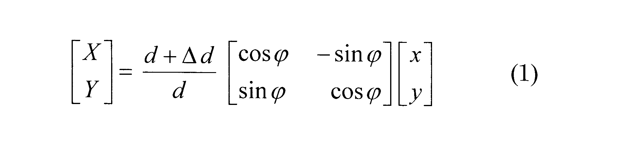
式(1)によれば、理論的な照射位置(x、y)は、θ方向にφだけ、r方向にΔdだけ、補正される。したがって、このようにしても、走査軌跡Bの同一の周上に位置する複数の理論的な照射位置(x,y)を、同一の補正値を用いてθ方向およびr方向に補正することができる。ここで、φとしてΘを用い、ΔdとしてRを用いればよい。
1 光走査型観察装置
2 挿入部
3 筐体
4 光源
5 駆動信号発生部
6 光走査部
7 光検出部
71 受光部
72 光検出器
8 DA変換器
9 集光レンズ
10 補正値取得装置
11 照射位置検出部
111 PSD
112 AD変換器
12 座標系変換部
13 照射位置計算部
14 乖離値算出部
15 補正値算出部
20 画像処理装置
21 AD変換器
22 記憶部
23 画素座標算出部
24 画像形成部
30 表示装置
100 光走査型観察システム
A 被写体
B 走査軌跡
2 挿入部
3 筐体
4 光源
5 駆動信号発生部
6 光走査部
7 光検出部
71 受光部
72 光検出器
8 DA変換器
9 集光レンズ
10 補正値取得装置
11 照射位置検出部
111 PSD
112 AD変換器
12 座標系変換部
13 照射位置計算部
14 乖離値算出部
15 補正値算出部
20 画像処理装置
21 AD変換器
22 記憶部
23 画素座標算出部
24 画像形成部
30 表示装置
100 光走査型観察システム
A 被写体
B 走査軌跡
Claims (11)
- 駆動信号に従って照明光を被写体上において渦巻き状の走査軌跡に沿って走査し、前記照明光の照射位置において発生する観察光を検出する光走査型観察装置に適用され、前記照明光の照射位置を補正するための補正値を取得する補正値取得装置であって、
前記被写体上の前記渦巻き状の走査軌跡の各周において少なくとも1つの前記照明光の照射位置を検出する照射位置検出部と、
前記光走査型観察装置から前記駆動信号を受信し、前記照射位置検出部によって検出された前記照射位置の理論的な照射位置を前記駆動信号に基づいて計算する照射位置計算部と、
前記照射位置計算部によって算出された前記理論的な照射位置と前記照射位置検出部によって検出された照射位置との差を乖離値として算出する乖離値算出部と、
前記渦巻き状の走査軌跡の同一の周における少なくとも1つの前記理論的な照射位置から算出された乖離値から前記走査軌跡の各周用の補正値を算出する補正値算出部とを備える補正値取得装置。 - 前記照射位置検出部が、前記走査軌跡の各周において複数の前記照明光の照射位置を検出し、
前記補正値算出部が、前記走査軌跡の同一の周上に位置する複数の前記照明光の前記理論的な照射位置から算出される乖離値の平均値を前記補正値として算出する請求項1に記載の補正値取得装置。 - 前記補正値算出部が、前記走査軌跡の中心を原点とし前記走査軌跡の周方向を偏角方向とする極座標系で表される前記補正値を算出する請求項1または請求項2に記載の補正値取得装置。
- 前記照射位置検出部が、前記照射位置として、前記極座標系における座標面と平行な座標面を有する2次元直交座標系における直交座標を検出し、
前記照射位置計算部が、前記極座標系における極座標として前記理論的な照射位置を算出し、
前記照射位置検出部によって検出された前記照射位置の直交座標を前記極座標系における極座標に変換する座標系変換部を備える請求項3に記載の補正値取得装置。 - 前記補正値算出部が、前記理論的な照射位置を偏角方向に補正するための補正値のみを算出する請求項3または請求項4に記載の補正値取得装置。
- 駆動信号に従って照明光を被写体上において渦巻き状の走査軌跡に沿って走査し、前記照明光の照射位置において発生する観察光を検出する光走査型観察装置に適用され、前記被写体の画像を形成する画像処理装置であって、
前記渦巻き状の走査軌跡の各周と対応付けて少なくとも1つずつ補正値を記憶する記憶部と、
前記光走査型観察装置から前記駆動信号を受信し、前記照明光の理論的な照射位置を前記駆動信号に基づいて計算し、算出された前記理論的な照射位置および前記記憶部に記憶されている補正値に基づいて画素座標を算出する画素座標算出部と、
前記観察光の検出信号を前記光走査型観察装置から受信し、前記画素座標算出部によって算出された前記画素座標および前記観察光の検出信号に基づいて画像を形成する画像形成部とを備え、
前記画素座標算出部が、前記理論的な照射位置を当該理論的な照射位置が位置する周と対応付けられている前記補正値を用いて補正し、補正された前記理論的な照射位置を前記画素座標として算出する画像処理装置。 - 前記記憶部が、前記走査軌跡の中心を原点とし前記走査軌跡の周方向を偏角方向とする極座標系で表される前記補正値を記憶する請求項6に記載の画像処理装置。
- 前記記憶部が、前記走査軌跡の各周用に1つずつ前記補正値を記憶し、
前記画素座標算出部が、前記渦巻き状の走査軌跡の同一の周上に位置する全ての前記理論的な照射位置を同一の前記補正値を用いて補正する請求項6または請求項7に記載の画像処理装置。 - 駆動信号を発生する駆動信号発生部と、該駆動信号発生部によって発生された前記駆動信号に従って照明光を被写体上において渦巻き状の走査軌跡に沿って走査する光走査部と、前記照明光の照射位置において発生する観察光を検出する光検出部とを備える光走査型観察装置と、
請求項1から請求項5のいずれかに記載の補正値取得装置と、
請求項6から請求項8のいずれかに記載の画像処理装置とを備える光走査型観察システム。 - 駆動信号に従って照明光を被写体上において渦巻き状の走査軌跡に沿って走査し、前記照明光の照射位置において発生する観察光を検出する光走査型観察方法に適用され、前記照明光の照射位置を補正するための補正値を取得する補正値取得方法であって、
前記被写体上の前記渦巻き状の走査軌跡の各周において少なくとも1つの前記照明光の照射位置を検出する照射位置検出ステップと、
前記照射位置検出ステップにおいて検出された前記照射位置の理論的な照射位置を前記駆動信号に基づいて計算する照射位置計算ステップと、
前記照射位置計算ステップにおいて算出された前記理論的な照射位置と前記照射位置検出ステップにおいて検出された照射位置との差を乖離値として算出する乖離値算出ステップと、
前記渦巻き状の走査軌跡の同一の周における少なくとも1つの前記理論的な照射位置から算出された乖離値から前記走査軌跡の各周用の補正値を算出する補正値算出ステップとを含む補正値取得方法。 - 駆動信号に従って照明光を被写体上において渦巻き状の走査軌跡に沿って走査し、前記照明光の照射位置において発生する観察光を検出する光走査型観察方法に適用され、前記被写体の画像を形成する画像処理方法であって、
前記渦巻き状の走査軌跡の各周と対応付けて少なくとも1つずつ補正値を記憶する記憶ステップと、
前記照明光の理論的な照射位置を前記駆動信号に基づいて計算し、算出された前記理論的な照射位置および前記記憶ステップにおいて記憶された補正値に基づいて画素座標を算出する画素座標算出ステップと、
前記画素座標算出ステップにおいて算出された前記画素座標および前記観察光の検出信号に基づいて画像を形成する画像形成ステップとを備え、
前記画素座標算出ステップにおいて、前記理論的な照射位置を当該理論的な照射位置が位置する周と対応付けられている前記補正値を用いて補正し、補正された前記理論的な照射位置を前記画素座標として算出する画像処理方法。
Priority Applications (2)
| Application Number | Priority Date | Filing Date | Title |
|---|---|---|---|
| JP2018518833A JPWO2017203585A1 (ja) | 2016-05-23 | 2016-05-23 | 補正値取得装置、画像処理装置、光走査型観察システム、補正値取得方法および画像処理方法 |
| PCT/JP2016/065225 WO2017203585A1 (ja) | 2016-05-23 | 2016-05-23 | 補正値取得装置、画像処理装置、光走査型観察システム、補正値取得方法および画像処理方法 |
Applications Claiming Priority (1)
| Application Number | Priority Date | Filing Date | Title |
|---|---|---|---|
| PCT/JP2016/065225 WO2017203585A1 (ja) | 2016-05-23 | 2016-05-23 | 補正値取得装置、画像処理装置、光走査型観察システム、補正値取得方法および画像処理方法 |
Publications (1)
| Publication Number | Publication Date |
|---|---|
| WO2017203585A1 true WO2017203585A1 (ja) | 2017-11-30 |
Family
ID=60411158
Family Applications (1)
| Application Number | Title | Priority Date | Filing Date |
|---|---|---|---|
| PCT/JP2016/065225 WO2017203585A1 (ja) | 2016-05-23 | 2016-05-23 | 補正値取得装置、画像処理装置、光走査型観察システム、補正値取得方法および画像処理方法 |
Country Status (2)
| Country | Link |
|---|---|
| JP (1) | JPWO2017203585A1 (ja) |
| WO (1) | WO2017203585A1 (ja) |
Cited By (1)
| Publication number | Priority date | Publication date | Assignee | Title |
|---|---|---|---|---|
| JP2018115967A (ja) * | 2017-01-19 | 2018-07-26 | 株式会社日立製作所 | 光走査装置、映像装置、及び距離計測装置 |
Citations (4)
| Publication number | Priority date | Publication date | Assignee | Title |
|---|---|---|---|---|
| JP2015136573A (ja) * | 2014-01-24 | 2015-07-30 | オリンパス株式会社 | 光走査型観察装置 |
| WO2015125976A1 (ja) * | 2014-02-21 | 2015-08-27 | オリンパス株式会社 | 光の走査軌跡の算出方法及び光走査装置 |
| JP2015206981A (ja) * | 2014-04-23 | 2015-11-19 | オリンパス株式会社 | 光走査型画像形成装置及び光走査型画像形成方法 |
| JP2016093243A (ja) * | 2014-11-12 | 2016-05-26 | オリンパス株式会社 | 光走査型観察システム |
-
2016
- 2016-05-23 WO PCT/JP2016/065225 patent/WO2017203585A1/ja active Application Filing
- 2016-05-23 JP JP2018518833A patent/JPWO2017203585A1/ja active Pending
Patent Citations (4)
| Publication number | Priority date | Publication date | Assignee | Title |
|---|---|---|---|---|
| JP2015136573A (ja) * | 2014-01-24 | 2015-07-30 | オリンパス株式会社 | 光走査型観察装置 |
| WO2015125976A1 (ja) * | 2014-02-21 | 2015-08-27 | オリンパス株式会社 | 光の走査軌跡の算出方法及び光走査装置 |
| JP2015206981A (ja) * | 2014-04-23 | 2015-11-19 | オリンパス株式会社 | 光走査型画像形成装置及び光走査型画像形成方法 |
| JP2016093243A (ja) * | 2014-11-12 | 2016-05-26 | オリンパス株式会社 | 光走査型観察システム |
Cited By (2)
| Publication number | Priority date | Publication date | Assignee | Title |
|---|---|---|---|---|
| JP2018115967A (ja) * | 2017-01-19 | 2018-07-26 | 株式会社日立製作所 | 光走査装置、映像装置、及び距離計測装置 |
| US11240402B2 (en) | 2017-01-19 | 2022-02-01 | Hitachi, Ltd. | Optical scanning device, imaging device, and distance measurement device |
Also Published As
| Publication number | Publication date |
|---|---|
| JPWO2017203585A1 (ja) | 2019-03-22 |
Similar Documents
| Publication | Publication Date | Title |
|---|---|---|
| US8882658B2 (en) | Endoscope system | |
| US8937714B2 (en) | Inspecting apparatus and inspecting method | |
| WO2015125976A1 (ja) | 光の走査軌跡の算出方法及び光走査装置 | |
| JP2012022971A (ja) | 走査透過電子顕微鏡における収差補正方法および収差補正装置 | |
| WO2017203585A1 (ja) | 補正値取得装置、画像処理装置、光走査型観察システム、補正値取得方法および画像処理方法 | |
| JP2016024141A (ja) | 架線位置測定装置及び方法 | |
| US11375883B2 (en) | Light-scanning endoscope, correcting apparatus for light scanning endoscope and light-scanning-endoscope operating method | |
| EP3097844A1 (en) | Optical scanning-type observing device | |
| US20170027443A1 (en) | Image pickup apparatus and method of controlling image pickup apparatus | |
| JP2012173243A (ja) | 3次元計測装置、および3次元計測方法 | |
| JP6640541B2 (ja) | レーザスキャナ | |
| WO2017037781A1 (ja) | 走査型観察装置 | |
| JP2018000795A (ja) | 内視鏡プロセッサ | |
| US10491873B2 (en) | Scanning observation apparatus and image display method of scanning observation apparatus | |
| WO2019012623A1 (ja) | 画像処理装置、光走査型観察システムおよび画像処理方法 | |
| JP2006162609A (ja) | 電子線を用いたパターン検査方法及びその装置 | |
| JP6899236B2 (ja) | 関係特定方法、関係特定装置、関係特定プログラム、補正方法、補正装置、及び補正用プログラム | |
| JP2012147831A (ja) | 走査位置補正装置 | |
| JP2007064965A (ja) | 光学素子の波面収差測定方法及び波面収差補正方法 | |
| KR102449039B1 (ko) | 광 단층 촬영 구강 스캐너 교정 장치 및 전 영역 스캔을 통한 교정 정보 획득 방법 | |
| WO2018116464A1 (ja) | 走査型画像取得装置および走査型画像取得システム | |
| JP2011008219A (ja) | レーザ走査顕微鏡および制御方法 | |
| JP6437808B2 (ja) | 光走査型観察システム | |
| JP5945390B2 (ja) | 観察装置、観察装置の作動方法及び画像処理プログラム | |
| JPWO2017037782A1 (ja) | 走査型観察装置 |
Legal Events
| Date | Code | Title | Description |
|---|---|---|---|
| ENP | Entry into the national phase |
Ref document number: 2018518833 Country of ref document: JP Kind code of ref document: A |
|
| NENP | Non-entry into the national phase |
Ref country code: DE |
|
| 121 | Ep: the epo has been informed by wipo that ep was designated in this application |
Ref document number: 16903067 Country of ref document: EP Kind code of ref document: A1 |
|
| 122 | Ep: pct application non-entry in european phase |
Ref document number: 16903067 Country of ref document: EP Kind code of ref document: A1 |