WO2017200150A1 - Clé - Google Patents
Clé Download PDFInfo
- Publication number
- WO2017200150A1 WO2017200150A1 PCT/KR2016/010698 KR2016010698W WO2017200150A1 WO 2017200150 A1 WO2017200150 A1 WO 2017200150A1 KR 2016010698 W KR2016010698 W KR 2016010698W WO 2017200150 A1 WO2017200150 A1 WO 2017200150A1
- Authority
- WO
- WIPO (PCT)
- Prior art keywords
- hook
- sliding
- latch
- jaw
- fixed
- Prior art date
Links
Images


Classifications
-
- B—PERFORMING OPERATIONS; TRANSPORTING
- B25—HAND TOOLS; PORTABLE POWER-DRIVEN TOOLS; MANIPULATORS
- B25B—TOOLS OR BENCH DEVICES NOT OTHERWISE PROVIDED FOR, FOR FASTENING, CONNECTING, DISENGAGING OR HOLDING
- B25B1/00—Vices
- B25B1/02—Vices with sliding jaws
-
- B—PERFORMING OPERATIONS; TRANSPORTING
- B25—HAND TOOLS; PORTABLE POWER-DRIVEN TOOLS; MANIPULATORS
- B25B—TOOLS OR BENCH DEVICES NOT OTHERWISE PROVIDED FOR, FOR FASTENING, CONNECTING, DISENGAGING OR HOLDING
- B25B1/00—Vices
- B25B1/06—Arrangements for positively actuating jaws
-
- B—PERFORMING OPERATIONS; TRANSPORTING
- B25—HAND TOOLS; PORTABLE POWER-DRIVEN TOOLS; MANIPULATORS
- B25B—TOOLS OR BENCH DEVICES NOT OTHERWISE PROVIDED FOR, FOR FASTENING, CONNECTING, DISENGAGING OR HOLDING
- B25B1/00—Vices
- B25B1/24—Details, e.g. jaws of special shape, slideways
-
- B—PERFORMING OPERATIONS; TRANSPORTING
- B25—HAND TOOLS; PORTABLE POWER-DRIVEN TOOLS; MANIPULATORS
- B25B—TOOLS OR BENCH DEVICES NOT OTHERWISE PROVIDED FOR, FOR FASTENING, CONNECTING, DISENGAGING OR HOLDING
- B25B11/00—Work holders not covered by any preceding group in the subclass, e.g. magnetic work holders, vacuum work holders
-
- B—PERFORMING OPERATIONS; TRANSPORTING
- B25—HAND TOOLS; PORTABLE POWER-DRIVEN TOOLS; MANIPULATORS
- B25B—TOOLS OR BENCH DEVICES NOT OTHERWISE PROVIDED FOR, FOR FASTENING, CONNECTING, DISENGAGING OR HOLDING
- B25B13/00—Spanners; Wrenches
- B25B13/10—Spanners; Wrenches with adjustable jaws
- B25B13/12—Spanners; Wrenches with adjustable jaws the jaws being slidable
- B25B13/20—Arrangements for locking the jaws
- B25B13/22—Arrangements for locking the jaws by ratchet action or toothed bars
-
- B—PERFORMING OPERATIONS; TRANSPORTING
- B25—HAND TOOLS; PORTABLE POWER-DRIVEN TOOLS; MANIPULATORS
- B25B—TOOLS OR BENCH DEVICES NOT OTHERWISE PROVIDED FOR, FOR FASTENING, CONNECTING, DISENGAGING OR HOLDING
- B25B13/00—Spanners; Wrenches
- B25B13/58—Jaw attachments
-
- B—PERFORMING OPERATIONS; TRANSPORTING
- B25—HAND TOOLS; PORTABLE POWER-DRIVEN TOOLS; MANIPULATORS
- B25B—TOOLS OR BENCH DEVICES NOT OTHERWISE PROVIDED FOR, FOR FASTENING, CONNECTING, DISENGAGING OR HOLDING
- B25B23/00—Details of, or accessories for, spanners, wrenches, screwdrivers
- B25B23/16—Handles
Definitions
- the present invention relates to a wrench, and more particularly, to a wrench that can be easily chucked and released of a workpiece, capable of firm chucking, and can also be used as a fixing jig.
- the wrench in order to chuck the pipe, etc., the chucking portion is configured to open in the form of a screw, there was a problem inconvenient to use quickly during work.
- the pipe wrench also used a rotary lever to chuck the workpiece to adjust the jaw spacing.
- the present invention has been made to solve the problems of the prior art as described above, and an object thereof is to provide a wrench that is easy to chuck and release the workpiece.
- the present invention has another object to provide a device that can be used as a fixing jig by applying the wrench.
- Wrench according to the present invention is a "b" shape
- the hook hook is provided at one end
- the rack hook is provided on the other end
- the other end of the sliding hook portion is inserted and accommodated
- the latch hook is formed to engage with the hook hook is formed
- the fixed latch portion is formed on one side of the fixed latch portion, is engaged with the rack gear
- the hook brake portion for controlling the sliding of the sliding hook portion is provided in the form of a lever
- the other side is lifted by the fixing lever portion, the screw tightening to secure the hook brake to engage the rack gear, it comprises a hook fixing portion for fixing the fixing lever part in a pressurized state.
- the wrench according to the present invention has an effect of easily chucking and releasing the work by configuring the chucking unit to move quickly and easily.
- the wrench according to the present invention there is an effect that can firmly chuck the workpiece.
- the wrench according to the present invention through the combination with the cradle, there is an effect that can be used as a fixing jig.
- the wrench according to the present invention it is possible to easily adjust the interval of the jig for holding the workpiece, there is an effect that can be firmly gripped.
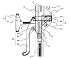
- FIG. 1 is a front view of a state in which the chucking portion of the wrench according to the first embodiment of the present invention is opened.
- Figure 2 is a front view of a closed state of the chucking portion of the wrench according to the first embodiment of the present invention.
- Figure 3 is a front view showing in detail the hook brake portion and the fixed lever portion of the wrench according to the first embodiment of the present invention.
- Figure 4 is a front view showing a cradle coupled to the wrench according to the first embodiment of the present invention.
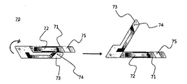
- FIG 5 is a bottom view of the holder coupled to the wrench according to the first embodiment of the present invention.
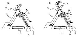
- Figure 6 (a) is a front view showing a coupling state of the wrench and the cradle according to the first embodiment of the present invention.
- Figure 6 (b) is a front view showing a state used as a fixing jig by combining the wrench and the cradle according to the first embodiment of the present invention.
- FIG. 7 is a structural diagram showing a basic state of a wrench according to Embodiment 2 of the present invention.
- FIG. 8 is a structural diagram showing a state in which the workpiece is chucked to the wrench according to the second embodiment of the present invention.
- FIG. 9 is a structural diagram of a state in which the workpiece is firmly fixed after chucking the workpiece to the wrench according to the second embodiment of the present invention.
- FIG. 10 is a structural diagram showing a state in which the hook and latch jaw of the wrench according to the second embodiment of the present invention is completely engaged.
- FIG. 11 is a view showing differently coupled state of the rack gear and rack fixing portion of the wrench according to the second embodiment of the present invention.
- Figure 12 shows a state in which the clearance is adjusted by the fine interval adjusting portion of the wrench according to the second embodiment of the present invention.
- FIG. 13 is a side sectional view showing a basic state of a wrench according to Embodiment 3 of the present invention.
- FIG. 14 is a side sectional view showing a state for using a wrench according to the third embodiment of the present invention.
- FIG. 15 is a side cross-sectional view illustrating a state in which a hook jaw and a latch jaw are spaced apart to chuck a workpiece in a wrench according to Embodiment 3 of the present invention.
- Figure 16 is a side cross-sectional view showing a process of moving the chucking member to adjust the height of the wrench according to the third embodiment of the present invention.
- 17 is a side sectional view showing a state where the height of the wrench according to the third embodiment of the present invention is increased.
- FIG. 18 is a side sectional view showing a state where a hook jaw and a latch jaw are spaced apart to chuck a workpiece in a wrench having a height increased according to Embodiment 3 of the present invention
- 19 is a plan view showing in detail the first rack gear and the second rack gear according to the third embodiment of the present invention.
- FIG. 21 is a perspective view of a wrench according to Embodiment 4 of the present invention.
- FIG. 22 is a side view of a wrench according to Embodiment 4 of the present invention.
- Figure 23 is a side view showing when the fixed chuck and the movable chuck in the wrench according to the fourth embodiment of the present invention.
- FIG. 24 is a cross-sectional view taken along the line AA ′ of the wrench according to the fourth embodiment of the present invention.
- connecting member 34 first elastic member
- latch tank 300 pin portion
- lever portion 510 handle portion
- first lever support portion 530 second lever support portion
- the wrench according to the first embodiment of the present invention as shown in Figures 1 to 2, a "hook" shape, the hook hook 11 is provided at one end, the rack hook 14 is provided on the other end (10), the other end of the sliding hook portion 10 is inserted and accommodated, the fixed latch portion 20, the latch latch 21 of the form that engages with the hook group 11 is formed, the fixed latch portion 20 It is formed on one side, is engaged with the rack gear 14, provided on the other side of the hook brake portion 30, the fixed latch portion 20 for controlling the sliding of the sliding hook portion 10, pressurizing one side
- the hook lever part 30 is fixed to the rack gear 14 so as to be engaged with the rack gear 14, and the screw is tightened, and one side presses the fixed lever part 40.
- It is configured to include a hook fixing part 50 for fixing in a closed state.
- the sliding hook portion 10 is a "b" shape, the hook group 11 is provided at one end, the rack gear 14 is provided at the other end.
- a jaw-shaped hook jaw 11 capable of chucking the pipe A is provided at one end of the body provided in an A-shape, and the other end thereof is described below. Consists of a bar shape that can be inserted into the fixed latch 20 of, the rack gear 14 is provided on one side.
- the hook jaw 11 can chuck the pipe A by forming a chucking portion in a form of engaging with the latch jaw 21 described below.
- the rack gear 14 is configured to mesh with the hook brake portion 30 described below so as to control sliding of the sliding hook portion 10.
- the other end of the sliding hook 10 is provided with a long hole rail hole 13 formed in the longitudinal direction.
- a sliding lever 12 protruding from the other end of the sliding hook 10 is further provided.
- the sliding lever 12 protrudes to the outside through the following sliding hole, and through the sliding of the sliding lever 12, it is possible to adjust the interval between the hook jaw 11 and the latch jaw 21.
- the fixed latch portion 20 has the other end of the sliding hook portion 10 inserted therein and engages with the hook portion 11. ) Is formed.
- the middle portion of the fixed latch 20 is further provided with a sliding hole 24 in the form of a long hole formed in the longitudinal direction.
- the sliding lever 12 protrudes through the sliding hole 24, and through the sliding of the sliding lever 12, the gap between the hook jaws 11 and the latch jaws 21 is adjusted. Can be.
- a hook portion (22) in the form of a hook (hook) is further provided to facilitate the mounting where the hook can be hooked.
- the hook portion 22 when the wrench is mounted on the cradle 70 of the following, it can be hooked to the following first wrench fixing portion 74 provided in the form of a bar.
- the latch 23 is provided at one end of the fixed latch 20, the latch 23 is provided.
- the latch 23 is formed at one end of the fixed latch portion 20 and is provided in a form penetrating the rail hole 13.
- the latch 23 is coupled to the rail hole 13 to limit the gap that extends in the longitudinal direction of the sliding hook portion 10. Therefore, the sliding hook portion 10 is moved by the length of the rail hole 13 by the latch 23.
- a spring 60 having an elastic force is provided inside the other end of the fixed latch 20, and is connected to the other end of the sliding hook 10.
- the hook braking portion 30 is formed on one side of the fixed latch portion 20 to be engaged with the rack gear 14 to control sliding of the sliding hook portion 10.
- the hook brake part 30 includes a rack fixing member 31, a pressing member 32, a connecting member 33, and a first elastic member 34. .
- the rack fixing member 31 has a tooth that is engaged with the rack gear 14 at one end thereof, and is configured to slide inclined toward the direction in which the sliding hook portion 10 is inserted.
- the rack fixing member 31 is provided in a rectangular shape inclined one side, the teeth are formed on the inclined surface.
- the rack fixing member 31 is provided diagonally with respect to the longitudinal direction of the sliding hook portion (10).
- the oblique line is provided as an oblique line having a form in which a gap is narrowed toward the other end direction of the sliding hook portion 10.
- the hook jaw 11 and the latch jaw 21 can be firmly fixed to the high pressure applied in the opening direction without play or slipping.
- the pressing member 32 is provided in a quadrangular shape in which one surface forms one end of the inclined shape, and the inclined surface is provided in contact with the other end of the rack fixing member 31.
- the pressing member 32 is slid in a direction perpendicular to the longitudinal direction of the sliding hook portion 10, when a force is applied in the direction of one end of the pressing member 32, the rack fixing member 31 Pressing the other end of the rack fixing member 31 is engaged with the rack gear (14).
- the connecting member 33 one end is connected to the pressing member 32, the other end is connected to the following fixed lever portion 40, the fixed lever portion 40 and the pressing member ( 32) to be interlocked.
- the first elastic member 34 is provided on one side of the rack fixing member 31, and when the pressure applied to one end of the pressing member is released, the first elastic member 34 is engaged with the rack gear 14.
- a spring is provided in which elastic force acts in the release direction.
- the fixed lever part 40 is provided on the other side of the fixed latch part 20, and when the one side is pressed, the other side is lifted in the form of a lever and the hook brake part 30 is connected to the rack gear 14. Press to engage.
- the fixed lever portion 40 is composed of a hinge portion 41, the pressing portion 42, the acting portion 43, the second elastic member.
- the hinge portion 41, the middle portion is connected to the other side of the fixed latch portion 20 in the form of a hinge
- the pressing portion 42 is provided in the form of a handle on one side.
- the acting portion 43 is configured in such a manner that a contact surface is formed on the other side of the fixed latch portion 20, and when the pressing portion 42 is pressurized, by the lever principle, the fixed latch portion 20 The contact surface moves in a way that opens.
- the hinge part 41 is moved by the second elastic member 44 so that when the pressure is released, the action part 43 is again formed so that the contact surface is formed on the other side of the fixed latch part 20.
- the first elastic member 34 and the second elastic member 44 is preferably composed of a torsion spring.
- the hook fixing part 50 is a part for fixing the fixing lever part 40 in a pressurized state, and a bolt 52 perpendicular to the longitudinal direction of the fixing latch part 20 is formed, and thus the operation is performed. It is fastened through the portion 43, the rotation lever 50 for rotating the bolt 52 is provided.
- the wrench is further provided with a cradle 70 that can be mounted in a form in which the other end of the hook portion 22 and the fixed latch 20 is supported, it can be used as a fixing jig.
- the holder 70 is configured to include a support portion 71, the support portion 73.
- the support portion 71 is provided horizontally with the ground, is provided in the form of a bar (bar) for supporting the ground, and is provided with a wing portion 72 to be extended to the side, it is possible to stably support the ground.
- the support portion 73 one end is connected to one end of the support portion 71 by a hinge, the other end is provided in a form inclined upward, as shown in Figure 6, through the hook portion 22 It is prepared in such a way that it can be done.
- the hook portion 22 may be hooked to the first wrench fixing portion 74 provided in a bar shape, and the other end of the fixed latch portion is seated on the second wrench fixing portion 75.
- the wrench is mounted.
- the second wrench fixing portion 75 is preferably provided with a hole inclined at the same angle as the inclination of the wrench.
- the support portion 71 and the support portion 73 may be provided in a bar shape of a single form.
- the wrench according to the second embodiment of the present invention as shown in Figure 7 to 10, the "b" shape, the hook hook 110 is provided at one end, the rack gear 120 is provided at one end of the other sliding Hook portion 100, the first elastic receiving portion 130 in the form of a hole formed in the inward direction from the other end of the sliding hook portion 100, the elastic support portion provided in the form of a protrusion on the other end of the other side of the sliding hook ( 140, the other end of the sliding hook portion 100 is inserted and accommodated, the fixed latch portion 200, the fixed latch portion 200 is formed with a latch jaw 220 of the form engaging with the hook jaw 110 at one end Is provided on one side of the inner side, the elastic support portion 140 is accommodated in the second elastic accommodating portion 210 is formed, a space for sliding, one end is formed in the step is accommodated in the first elastic accommodating portion 130 , The pin part 300 sliding in the longitudinal direction along the first elastic accommodating part 130, and It is coupled to the other side of the fixed latch portion 200, in the form of being engaged with the rack
- the sliding hook portion is a "b" shape, one end hook hook 110 is provided, the other end is provided with a rack gear 120.
- a jaw-shaped hook jaw 110 that can be chucked to the workpiece (A) is provided at one end of the body is provided in the "b" shape, the other end is fixed to the latch portion 200 below Consists of a bar shape that can be inserted, the rack gear 120 is provided on one side.
- the hook group 110 may form a chucking unit in a form of meshing with the latch unit 220 described below to chuck the pipe.
- the rack gear 120 is configured to be engaged with the hook brake portion of the following to secure the sliding of the sliding hook portion 100.
- the other end portion of the sliding hook portion 100 is provided with the following first elastic receiving portion 130.
- the sliding hook part 100 is slid in more detail below.
- the sliding hook portion 100 may further include a fine interval adjusting portion 150 that can finely adjust the interval between the hook group 110 and the latch group 220.
- the fine spacing adjusting part 150 has a play that may be minutely generated when the workpiece A is chucked between the hook jaw 110 and the latch jaw 220 below.
- the screw member 151 and the nut member 152 is composed.
- the sliding hook portion 100 is configured to be coupled to the end of the first member 101 and the first member 101 is inserted into the fixed latch portion 200 in the longitudinal direction, the hook group ( The second member 102 may be provided.
- the first member 101 has a through hole provided with a screw thread at an end thereof, and the screw member 151 is inserted into the through hole.
- a nut member 152 that can accommodate the screw member 151 coupled through the through hole is fixedly provided.
- the nut member 152 may be configured in any form without a screw thread, if the screw member 151 does not fall out and can be resilient.
- the gap between the hook group 110 and the latch group 220 can be finely reduced. Therefore, when chucking the workpiece A between the hook jaw 110 and the latch jaw 220, it is possible to selectively control the fine play that may occur.
- the first elastic accommodating part 130 is provided in the form of a hole formed in the inward direction at the other end of the sliding hook part 100.
- the first elastic accommodating part 130 is a part for accommodating the first spring part 600 and the pin part 300, and a step is formed in the inward direction of the end part. It is preferable that the first spring portion 600 is configured not to protrude to the outside.
- the elastic support portion 140 is provided in the form of a projection on the other end of the sliding hook portion 100.
- the elastic support part 140 is configured to support the elastic force generated by the second spring part 700 described below in the second elastic accommodating part 210 to the sliding hook part 100. .
- the end portion of the second spring portion 700 may be configured in any form as long as it is supported to be stably supported, and configured to be slid along the inside of the second elastic accommodation portion 210 below.
- the fixed latch portion 200, the other end of the sliding hook portion 100 is inserted and received, the latch portion 220 of the form that is engaged with the hook group 110 is formed at one end.
- the latch jaw 220 is provided in the form of a jaw capable of chucking the work A, similarly to the hook jaw 110.
- the second elastic accommodating part 210 is provided on one side of the fixed latch part 200, and a space in which the elastic support part 140 is accommodated and slid is formed.
- the second elastic accommodating part 210 includes a space in which the second spring part 700 below is accommodated together with the elastic support part 140, and the elastic support part 140 is slid along an inner side thereof. It consists of.
- the second spring portion 700 provided inside the second elastic accommodating part 210 is provided between the inner wall and the elastic support part 140 formed inside the other end of the second elastic accommodating part 210.
- An elastic force acts so that the sliding hook portion 100 slides in a direction in which the gap between the hook jaw 110 and the latch jaw 220 is far.
- the pin portion 300 one end is formed with a step is accommodated in the first elastic receiving portion 130, the other end is accommodated in the fixed latch portion 200, the first elastic receiving Sliding in the longitudinal direction along the portion 130.
- the pin 300 has the other end hinged to the second lever support part 530, and when pressing the handle part 510, the first lever support part 520 and the second lever support part ( By the interlocking of the 530, the sliding hook 100 is slid in the other end direction.
- the hook braking unit 400 is coupled to the other side of the fixed latch unit 200, is engaged with the rack gear 120, it is provided to fix the sliding of the sliding hook portion 100. do.
- the hook brake 400 is configured to include a rack fixing part 410, a fixed pressing part 420, a third spring portion 430.
- the rack fixing portion 410 is provided on the other side of the fixed latch portion 200, is provided to be able to slide in an oblique form of the slope is lowered in the direction in which the sliding hook portion 100 is inserted, the end A tooth that can be engaged with the rack gear 120 is formed.
- the teeth of the rack fixing portion 410 and the teeth of the rack gear 120 is configured in a rectangular shape, as shown in Figure 11, the hook saw 110 in the form that the vertical saw blade surfaces are engaged with each other. It is configured to limit the gap between the latch tank 220 is widened.
- the fixed pressing unit 420 is configured in the form of a lever on the other side of the fixed latch 200.
- the other end When one end of the fixed pressing unit 420 is lifted by the lever unit 500, the other end may be configured to press the rack fixing unit 410 in an oblique direction in the direction in which the rack gear 120 is bitten.
- the third spring portion 430 is provided in the form of a torsion spring inside the fixed pressing portion 420.
- the fixed pressing part 420 When no force acts on one end of the fixed pressing part 420, the fixed pressing part 420 does not apply pressure to the rack fixing part 410 by the third spring part 430. You can put it back.
- the lever unit 500 is. It is provided on the other side of the fixed latch portion 200 is hinged to the other end of the pin portion 300, when pressing one side the pin portion 300 in the direction in which the gap between the hook jaw 110 and the latch jaw 220 is reduced It is provided to be able to slide.
- the lever part 500 includes a handle part 510, a first lever support part 520, and a second lever support part 530.
- the handle portion 510 is connected to the other side of the fixed latch portion 200 in the form of a lever is configured so that the user can press the end by hand.
- the rack fixing portion 410 and the rack gear 120 may be engaged by applying a force to the fixed pressing portion 420.
- the other end of the handle portion 510 and one end of the fixed pressing portion 420 is configured based on a state spaced apart at a predetermined interval, when the handle portion 510 is rotated by a predetermined angle or more Only configured to press one end of the fixed pressing portion.
- the rack fixing part is pressed by the fixed pressure part 420.
- the 410 may be engaged with the rack gear 120 to fix the sliding of the sliding hook part 100.
- the chucking of the workpiece (A) by only the operation of releasing the pressure of the handle can be fixed firmly, after chucking the workpiece (A) only by a simple operation of pressing the handle. You can turn it off.
- the interval between the hook portion 510 and the fixed latch portion 200 is proportional to the size of the workpiece, so that the gap between the hook jaw 110 and the latch jaw 220 is not widened or reduced, and the handle 510 Even if the gap between the fixed latch unit 200 and the fixed latch 200 does not greatly open, the gap between the hook jaw 110 and the latch jaw 220 can be maintained at a maximum, so that it is easy to work with one hand.
- the first lever support part 520 has one end hinged to the other side of the fixed latch part 200, and the other end part which is rotatably provided to support one end of the handle part 510.
- One end of the second lever support part 530 is hingedly coupled to the other end of the first lever support part 520, and the other end is hinged to the other end of the pin part 300.
- the other end of the first lever support part 520 is hingedly connected to one end of the second lever support part 530, and the other end of the second lever support part 530 is the other end of the pin part 300. It is hinged and the pin portion 300 is configured to be slidable only in the longitudinal direction through the pressing of the handle portion 510, the pin portion 300 is the other end direction of the sliding hook portion 100 Is sliding.
- the first spring part 600 is accommodated in the first elastic accommodating part 130 and provided at one end thereof so as to be supported by a step formed at one end of the pin part 300.
- the support point is formed on the step formed in the other end of the sliding hook portion 100 and one end of the pin portion 300.
- the second spring portion 700 is provided in the second elastic receiving portion 210 so that one end thereof may be supported by the elastic support portion 140.
- the second spring portion 700, the support point is formed on the other end of the second elastic receiving portion 210 and the elastic support portion 140.
- the other end of the second elastic receiving portion 210 is fixed inside, so that the elastic force acts on the elastic support portion 140 by the second spring portion 700, the hook tank 110 and the latch
- the sliding hook portion 100 is slid in a direction away from the jaw 220.
- the first spring portion 600 moves the sliding hook portion 100 in a direction in which the gap between the hook portion 110 and the latch portion 220 is reduced.
- the second spring portion 700 operates the sliding hook portion 100 in a direction in which the gap between the hook jaw 110 and the latch jaw 220 is farther away.
- the elastic force of the first spring portion 600 must be higher than the elastic force of the second spring portion 700.
- the elastic force acts in the direction away from the hook jaw 110 and the latch jaw 220.
- the pin portion 300 may be pushed to the pin portion 300 by the pressing of the handle portion 510. Even if it is sliding in the other end direction of the second spring portion 700 is applying a pressure to the sliding hook portion 100 in the direction in which the distance between the hook jaw 110 and the latch jaw 220, the elastic force is low The size of the first spring portion 600 is reduced, and the slide hook portion is held without moving.
- the elastic force of the first spring portion 600 is configured to be higher than the elastic force of the second spring portion 700.
- the receiving space is formed inside
- the fixing member 1100 is provided in the bar shape with the top and one end open, seated on the ground
- An accommodation space is formed therein, the upper, lower and one ends of which are provided in a bar shape are received in the inside of the fixing member 1100, and the other end of the other end of the fixing member 1100 so that one end can be rotated up and down.
- the connecting member 1200 is coupled to the end and the hinge 900, the guide hole 1210 is provided in the form of a long hole penetrating the side along the longitudinal direction, is accommodated in the connecting member 1200, the guide hole ( 1210 is movable, and comprises a chucking member 1300 capable of chucking in the form of a jaw (jaw).
- the fixing member 1100 is provided with an accommodating space therein, and is provided in a bar shape having an upper portion and an end portion thereof open and seated on the ground.
- the fixing member 1100 is configured to be easily stored in a state where the connection member 1200 and the chucking member 1300 are accommodated, and when used as a wrench according to the present invention, is stable. It is configured to support the ground.
- the cross-sectional area is preferably configured to be wider toward the lower side to form a stable contact surface with the ground.
- the fixing member 1100 includes a first mounting portion 1110, a second mounting portion 1120, and a third mounting portion 1130, wherein the first mounting portions 1110 to 3rd.
- the mounting portion 1130 it is possible to adjust the height of the chucking member 1300 below.
- the first mounting portion 1110 is provided in a notch shape parallel to the ground on one end of the fixing member 1100, as shown in Figure 13, the connecting member 1200 and the chucking member When the 1300 is configured to be parallel to the ground in a state of low height is configured to minimize the volume for easy storage, it is provided to catch the following second locking pin (1323).
- the chucking member 1300 and the connection member 1200 may be prevented from moving up and down.
- the second mounting portion 1120 is provided in a notch shape formed downward from the top, and as shown in FIG. 17, when the height of one end of the chucking member 1300 described below is increased, The second locking pins 1323 are provided to be mounted thereon.
- the other end of the following chucking member 1300 is fixed so that it may not rotate forward and backward, and the said operation
- the third mounting part 1130 may have a lower end such that the other end of the chucking member 1300 may be inserted and mounted. In the form of a groove.
- the other end of the chucking member 1300 may be formed in any form as long as it can be inserted or mounted.
- the third mounting portion 1130 it is possible to prevent the rotation of the chucking member 1300 to the front and rear direction to be fixed more stably.
- connection member 1200 is formed in the receiving space therein, the upper, lower and one end is provided in the shape of a bar open to be accommodated in the interior of the fixing member 1100, the other end is rotatable up and down An end is coupled to the other end of the fixing member 1100 and the hinge 900, and a guide hole 1210 having a long hole shape penetrating a side surface in the longitudinal direction is provided.
- the guide hole 1210, the first locking pin 1322 is to move across, and the configuration to adjust the height of the chucking member 1300 below with the rotation of the connecting member 1200,
- the first locking part 1211, the second locking part 1212, and the third locking part 1213 are further included.
- the first locking portion 1211 is provided with a notch formed upwardly at one end.
- the second locking portion 1212 is provided with a notch formed downward from the middle one point.
- connection member 1200 and the chucking member 1300 are connected to the ground. It is parallel and can be used as a wrench in a low position.
- the third locking portion 1213 is provided with a notch formed downward from the other end.
- the fixing member 1100, the connecting member 1200, and the chucking member 1300 When the first locking pin 1322 is accommodated in the third locking portion 1213, as shown in FIG. 13, the fixing member 1100, the connecting member 1200, and the chucking member 1300 below.
- the volume is minimized in a state of being in close contact and is configured in an easy state of storage.
- the chucking member 1300 is accommodated in the connection member 1200, is movable along the guide hole 1210, and is provided to enable chucking in the form of a jaw.
- the chucking member 1300 is a part capable of fixing a workpiece for machining, and includes a sliding hook part 1310, a fixed latch part 1320, a locking part 1330, and a pinion gear 1340. It is configured to include.
- the sliding hook 1310 is a 'b' shape, is provided with a hook group 1311 is formed with teeth at one end, the other end, as shown in Figure 19, the first rack gear (side) 1312 and the second rack gear 1313 is provided, as shown in Figure 18, the chucking guide hole 1314 in the form of a long hole formed in the longitudinal direction at one end is provided.
- the first rack gear 1312 is configured to be engaged with the following fixed teeth 1331, and the locking mechanism 1330, the hook of the hook 1311 and the latch of the latch 1321 Allow the gap to remain fixed.
- the second rack gear 1313 is configured to be engaged with the pinion gear 1340, and is configured to adjust the distance between the hook jaw 1311 and the latch jaw 1321 below.
- a configuration capable of adjusting or fixing the gap between the hook group 1311 and the latch unit 1321 will be described in more detail below.
- the chucking guide hole 1314 is connected to the following first locking pin 1322 to limit the movable range of the sliding hook 1310.
- the fixed latch portion 1320 has the other end of the sliding hook portion 1310 inserted therein, and has a sawtooth latch tank 1321 engaging with the hook portion 1311 at one end thereof.
- one end of the protrusion projecting in the form of protrusions are inserted into the chucking guide hole 1314 and the guide hole 1210 and the first locking pin 1322 and the other end in parallel with the first locking pin 1322
- the second locking pins 1323 are protruded to be selectively inserted into the first mounting portion 1110, the second mounting portion 1120, and the third mounting portion 1130.
- the locking portion 1330 is provided in a form inserted into one end of the other end of the fixed latch portion 1320, and engaged with the first rack gear 1312 to hook the hook 1311 and latch 1321. It is provided to fix the interval.
- the locking part 1330 includes a fixed tooth part 1331, a rotating lever part 1332, and a bracket part 1333.
- the fixed tooth portion 1331 is provided in a quadrangular shape in which an inclined surface is formed on one surface, the tooth is formed to be engaged with the first rack gear 1312 on one surface, the other end of the latch tank 1321 It is arranged to be rotated back and forth along the diagonal line is located in the diagonal line of the shape narrowing the interval in the direction.
- the teeth of the fixed tooth portion 1331 and the first rack gear 1312 are configured in a right triangle shape, and the hook jaw in a form in which vertical saw blade surfaces are engaged with each other. 1311 and the latch tab 1321 are configured to limit the gap between the gaps.
- the rotary lever part 1332 is connected to the rod-shaped rod formed on the other side of the fixed teeth 1133, the handle is provided at the end.
- the rotary lever part 1332 is connected to the other side of the fixed tooth part 1331 so that the fixed tooth part 1331 is not rotated even when the handle of the rotary lever part 1332 is rotated. do.
- the bracket portion 1333 is formed on the inner circumferential surface of the screw thread for accommodating the rod shape of the rotary lever portion, and is fixed between the rotary lever portion 1332 and the fixed tooth portion 1331.
- the pinion gear 1340 is provided at the other end of the fixed latch portion 1320, and is engaged with the second rack gear 1313 to be rotatable by sliding the sliding hook portion 1310. .
- the pinion gear 1340 is further provided with a lever hole (1341) for rotating the pinion gear by inserting a lever on the central axis, by the lever hole (1341), selectively using the lever
- the gap between the hook group 1311 and the latch group 1321 can be controlled.
- the pinion gear 1340 may be rotated by rotating the lever, and through this, the sliding hook 1310 may be slid more conveniently to the hook jaw ( 1311 and the latch tank 1321 can be controlled.
- the lever may be configured in any form as long as it is easily removable, and the lever hole 1341 may also be configured in any form as long as the lever can be inserted therein.
- the other end of the sliding hook portion 1310 and the fixed latch portion 1320 is provided with a spring 1350, it is possible to more easily reduce the gap between the hook group 1311 and the latch group 1321.
- the other end of the sliding hook portion 1310 and the other end of the fixed latch portion 1320 are connected by a spring 1350, the elastic force acts in the direction in which the gap between the hook group 1311 and the latch group 1321 is reduced do.
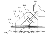
- the wrench according to the fourth embodiment of the present invention the base portion 2010 for supporting the ground in the form of a plate, the rail groove portion formed in the longitudinal direction on the base portion 2010 (top) 2020), a fixing jaw portion 2030 provided on one side of the base portion 2010 to support the workpiece, a support bracket portion 2040 provided on the other side of the base portion 2010, and the support bracket portion 2040. It is inserted and moved along the rail groove portion 2020, one end portion is fixed to the movable jaw portion 2050, the support bracket portion 2040 to secure the workpiece in the form of engaging with the fixed jaw portion 2030, the movable It is configured to include a locking portion 2060 for fixing the jaw portion 2050.
- the base part 2010 supports the surface in plate shape.
- the said base part 2010 is comprised from a metal plate material.
- it may be configured in any form as long as it can stably support the ground.
- the cross-sectional area is wider toward the bottom, or the support is further provided on both sides, it may be configured in the form of forming two or more additional contacts with the ground.
- the rail groove portion 2020 is formed in the longitudinal direction on the base portion 2010.
- the rail groove portion 2020 is provided with a groove formed in the longitudinal direction on the base portion 2010.
- the movable tub 2050 can be rotated forward and backward.
- the fixing jaw portion 2030 is provided on the upper side of the base portion 2010 to support the workpiece.
- the fixing jaw portion 2030 is provided with a fixing chuck 2031 is formed with a surface perpendicular to the ground.
- the workpiece is positioned and fixed between the fixed chuck 2031 and the movable chuck 2051 described below.
- the fixing chuck 2031 may be formed with a plurality of protrusions or sawtooth in order to effectively fix the workpiece.
- the fixing tub 2030 may be further provided with a fixing hole 2032 penetrating to the side.
- the fixing hole 2032 may be used for mounting a workpiece having a length such as rebar.
- the support bracket part 2040 is provided on the other side of the upper part of the base part 2010.
- the support bracket portion 2040 is formed with a through-hole penetrating in the longitudinal direction of the base portion 2010, the movable jaw portion 2050 is inserted.
- the movable tub 2050 is supported by the support bracket 2040 and slides forward and backward.
- a pinion gear 2070 is provided, as shown in FIG.
- the pinion gear 2070 is configured to be parallel to the ground and to be perpendicular to the moving direction of the movable jaw portion 2050 to be engaged with the second rack gear 2053 described below.
- the pinion gear 2070 is provided with a lever hole 2071 into which a lever can be inserted on a central axis.
- the pinion gear 2070 may rotate to move the movable jaw 2050 forward and backward.
- the lever may be selectively used as necessary, and more preferably, in order to fix the workpiece, the movable jaw portion (see below) is formed in such a manner that the gap between the fixed chuck 2031 and the movable chuck 2051 is narrowed. After quickly sliding the 2050, the lever may be inserted into the lever hole 2071 to squeeze the workpiece more strongly, and then rotated.
- the lever may be used as long as it is easy to use various types of wrenches, drivers and the like.
- lever hole 2071 may be configured in any form as long as the lever can be inserted therein.
- the movable jaw portion 2050 is inserted through the support bracket portion 2040, moves along the rail groove portion 2020, and fixes the workpiece in a form in which one end thereof is engaged with the fixing jaw portion 2030. do.
- one end surface of the movable jaw 2050 is provided with a movable chuck 2051, and is engaged with the fixed chuck 2031.
- the movable chuck 2051 may have a plurality of protrusions or a sawtooth shape for effectively fixing a workpiece.
- the movable jaw portion 2050, the first rack gear 2052 having the teeth formed in the upper direction in the longitudinal direction on the top and the second rack gear 2053 in which the teeth are formed downward in the longitudinal direction on the upper both sides. Is composed.
- the first rack gear 2052 is configured to be engaged with the following fixed tooth portion 2061, and can fix the movable jaw portion 2050 without moving.
- the second rack gear 2053 is configured to be engaged with the pinion gear 2070, and when the pinion gear 2070 is rotated by the lever that is selectively used, the movable nail 2020 is correspondingly provided. Can be moved forward and backward.
- a handle portion 2054 is provided at the other end of the movable tub.
- the handle portion 2054 is configured in a form that is easy to grasp so that the user can easily hold the movable tub 2050 to move quickly.
- any shape that can be held by the hand can be configured.
- the handle portion 2054 is configured, the user can simply slide the movable tank 2050 quickly.
- the locking part 2060 is provided inside the upper portion of the support bracket part 2040 to fix the movable jaw part 2050.
- the locking portion 2060 includes a fixed tooth portion 2061, a rotary lever portion 2062, a nut bracket portion 2063.
- the fixed tooth portion 2061 is provided in a shape accommodated in the upper inner side of the support bracket portion 2040, one side of which is inclined in a quadrangular shape having one side inclined.
- a tooth is formed in the
- the tooth is engaged with the first rack gear 2052 and is positioned in an oblique line in a shape in which a gap is narrowed toward the one end of the movable tub 2050.
- the fixed tooth portion 2061 is rotated back and forth along the oblique line and engaged with the first rack gear 2052, so that the movable jaw 2050 moves in a direction away from the fixed jaw portion 2030. Can be restricted.
- the teeth of the fixed tooth portion 2061 and the first rack gear 2052 are configured in a right triangle shape, and the vertical surfaces of the right triangle are engaged with each other. It is configured to limit the gap between the fixing tank 31 and the movable tank 51.
- the rotary lever portion 2062 is connected to the rod-shaped rod formed on the other side of the fixed tooth portion 2061, the handle portion is provided at the end.
- the rotating lever part 2062 is connected to the other side of the fixed tooth part 2061 so that the fixed tooth part 2061 is connected so as not to rotate even when the rotating lever part 2062 rotates.
- the nut bracket portion 2063 is provided to be fixed between the rotary lever portion 2062 and the fixed tooth portion 2061.
- the fixed tooth portion 2061 is supported so that it can be rotated diagonally.
- a screw thread formed on the rod-shaped portion of the rotary lever portion 2062 is coupled to the nut bracket portion 2063, and when the rotary lever portion 2062 is rotated, the nut bracket portion 2063 is fixed. As a result, the rotary lever part 2062 is moved forward and backward in the oblique direction.
- the fixed tooth portion 2061 may move in the diagonal line and may be engaged with or released from the first rack gear 2052.
Landscapes
- Engineering & Computer Science (AREA)
- Mechanical Engineering (AREA)
- Gripping Jigs, Holding Jigs, And Positioning Jigs (AREA)
Abstract
La présente invention se rapporte à une clé et, plus particulièrement, à une clé qui peut facilement serrer un objet de travail et libérer ce dernier, qui peut serrer fermement ce dernier et qui peut également être utilisée comme gabarit de maintien. La clé selon la présente invention comprend : une partie de crochet coulissant ayant une forme de L, ayant une mâchoire de crochet disposée sur une extrémité de cette dernière, et ayant un engrenage à crémaillère disposé sur l'autre extrémité de cette dernière; une partie de verrouillage de maintien ayant une mâchoire de verrouillage formée sur cette dernière et formée de sorte à venir en prise avec la mâchoire de crochet, l'autre extrémité de la partie de crochet coulissant étant insérée/contenue dans la partie de verrouillage de maintien; une partie de freinage de crochet formée sur un côté de la partie de verrouillage de maintien et formée de sorte à venir en prise avec l'engrenage à crémaillère, ce qui permet de commander le coulissement de la partie de crochet coulissant; une partie de levier de maintien disposée sur l'autre côté de la partie de verrouillage de maintien et configurée de telle sorte que, lorsqu'un côté de la partie de levier de maintien est mis sous pression, l'autre côté de ce dernier soit soulevé dans un type de levier, ce qui permet de maintenir la partie de freinage de crochet de sorte à venir en prise avec l'engrenage à crémaillère; et une partie de maintien de crochet qui maintient, au moyen d'une fixation par vis, la partie de levier de maintien tandis qu'un côté de cette dernière reste sous pression. La clé selon la présente invention est avantageuse en ce qu'elle comporte une partie de serrage configurée de sorte à se déplacer rapidement et de manière commode de telle sorte que l'objet de travail puisse être facilement serré et libéré. La clé selon la présente invention est également avantageuse en ce que l'objet de travail peut être serré fermement. La clé selon la présente invention est également avantageuse en ce que, par couplage avec une table de cintrage, elle peut être utilisée comme gabarit de maintien.
Applications Claiming Priority (8)
| Application Number | Priority Date | Filing Date | Title |
|---|---|---|---|
| KR10-2016-0059913 | 2016-05-17 | ||
| KR1020160059913A KR101812413B1 (ko) | 2016-05-17 | 2016-05-17 | 렌치 |
| KR1020160077164A KR101855704B1 (ko) | 2016-06-21 | 2016-06-21 | 바이스 |
| KR1020160077169A KR101886497B1 (ko) | 2016-06-21 | 2016-06-21 | 바이스 |
| KR10-2016-0077164 | 2016-06-21 | ||
| KR10-2016-0077169 | 2016-06-21 | ||
| KR1020160113770A KR101768389B1 (ko) | 2016-09-05 | 2016-09-05 | 렌치 |
| KR10-2016-0113770 | 2016-09-05 |
Publications (1)
| Publication Number | Publication Date |
|---|---|
| WO2017200150A1 true WO2017200150A1 (fr) | 2017-11-23 |
Family
ID=60325279
Family Applications (1)
| Application Number | Title | Priority Date | Filing Date |
|---|---|---|---|
| PCT/KR2016/010698 WO2017200150A1 (fr) | 2016-05-17 | 2016-09-23 | Clé |
Country Status (1)
| Country | Link |
|---|---|
| WO (1) | WO2017200150A1 (fr) |
Cited By (3)
| Publication number | Priority date | Publication date | Assignee | Title |
|---|---|---|---|---|
| CN108506616A (zh) * | 2018-05-24 | 2018-09-07 | 王真 | 一种输送管道接口扎紧工具 |
| CN110270953A (zh) * | 2019-07-25 | 2019-09-24 | 魏长同 | 一种口径可调扳手 |
| TWI740386B (zh) * | 2020-02-19 | 2021-09-21 | 詠統工業股份有限公司 | 腳踏車維修架 |
Citations (5)
| Publication number | Priority date | Publication date | Assignee | Title |
|---|---|---|---|---|
| US1363819A (en) * | 1920-01-17 | 1920-12-28 | Simerson | Adjusting mechanism for wrenches and the like |
| US5823076A (en) * | 1996-05-16 | 1998-10-20 | Binkowski; Kazimierz M. | Adjustable, ratcheting gear wrench for pipes and bolts |
| KR200259950Y1 (ko) * | 2001-10-10 | 2002-01-05 | 주식회사 에스엠씨 | 바이스 |
| US20090289404A1 (en) * | 2008-05-21 | 2009-11-26 | Michael Curt Stark | Precision sine vise |
| US20140061988A1 (en) * | 2012-08-30 | 2014-03-06 | Emerson Electric Co. | Integrated foot vise and wrench |
-
2016
- 2016-09-23 WO PCT/KR2016/010698 patent/WO2017200150A1/fr active Application Filing
Patent Citations (5)
| Publication number | Priority date | Publication date | Assignee | Title |
|---|---|---|---|---|
| US1363819A (en) * | 1920-01-17 | 1920-12-28 | Simerson | Adjusting mechanism for wrenches and the like |
| US5823076A (en) * | 1996-05-16 | 1998-10-20 | Binkowski; Kazimierz M. | Adjustable, ratcheting gear wrench for pipes and bolts |
| KR200259950Y1 (ko) * | 2001-10-10 | 2002-01-05 | 주식회사 에스엠씨 | 바이스 |
| US20090289404A1 (en) * | 2008-05-21 | 2009-11-26 | Michael Curt Stark | Precision sine vise |
| US20140061988A1 (en) * | 2012-08-30 | 2014-03-06 | Emerson Electric Co. | Integrated foot vise and wrench |
Cited By (3)
| Publication number | Priority date | Publication date | Assignee | Title |
|---|---|---|---|---|
| CN108506616A (zh) * | 2018-05-24 | 2018-09-07 | 王真 | 一种输送管道接口扎紧工具 |
| CN110270953A (zh) * | 2019-07-25 | 2019-09-24 | 魏长同 | 一种口径可调扳手 |
| TWI740386B (zh) * | 2020-02-19 | 2021-09-21 | 詠統工業股份有限公司 | 腳踏車維修架 |
Similar Documents
| Publication | Publication Date | Title |
|---|---|---|
| WO2021206297A1 (fr) | Serre-câble de type à cliquet à double verrouillage d'engrenage électrique externe pour ligne sous tension indirecte, et procédé de construction de ligne sous tension indirecte pour ajustement d'affaissement, travail de tension mécanique, et remplacement d'isolateur de suspension l'utilisant | |
| WO2022085943A1 (fr) | Bras de levage isolé de type à rouleau mobile pour fils sous tension indirects et procédé sans coupure pour fils sous tension indirects l'utilisant | |
| WO2018110856A1 (fr) | Dispositif de rotation | |
| WO2022010061A1 (fr) | Appareil de support d'écran | |
| WO2015160099A1 (fr) | Appareil d'affichage | |
| WO2012087057A2 (fr) | Appareil pour le traitement de vêtements | |
| WO2010068070A2 (fr) | Rasoir à deux faces | |
| WO2020145718A1 (fr) | Substrat d'affichage | |
| WO2016026127A1 (fr) | Machine de bobinage de bobine et dispositif de limitation de celle-ci, et procédé de bobinage de bobine d'un moteur | |
| WO2017116053A1 (fr) | Ensemble loquet pour porte de coffre de véhicule | |
| WO2017200150A1 (fr) | Clé | |
| WO2015142122A1 (fr) | Appareil de traitement de linge | |
| WO2020209502A1 (fr) | Dispositif d'empilement d'éléments de batterie secondaire et système de fabrication le comprenant | |
| WO2015088175A1 (fr) | Appareil de pliage d'appuie-tête | |
| WO2021210713A1 (fr) | Poignée affleurante pour portière de véhicule | |
| WO2020179965A1 (fr) | Appui-tête | |
| EP3105519A1 (fr) | Réfrigérateur | |
| WO2019009533A1 (fr) | Ensemble de profilés | |
| WO2019112396A1 (fr) | Boîtier de téléphone mobile | |
| WO2020246730A1 (fr) | Aspirateur | |
| WO2016099145A2 (fr) | Blender intelligent et son procédé de fonctionnement | |
| WO2021235646A1 (fr) | Sèche-cheveux | |
| WO2012141399A1 (fr) | Appareil permettant de fabriquer un poteau électrique en béton doté de plateaux supérieur et inférieur améliorés et procédé permettant de fabriquer le poteau électrique à l'aide de celui-ci | |
| WO2022119089A1 (fr) | Bouton de vitesses de véhicule | |
| WO2024019346A1 (fr) | Tendeur à cliquet d'engrenage d'entraînement rotatif de type à pendule à changement de direction automatique pour fil sous tension indirect à commande de distance de tension illimitée et procédé de distribution de non-puissance de fil sous tension indirect l'utilisant |
Legal Events
| Date | Code | Title | Description |
|---|---|---|---|
| NENP | Non-entry into the national phase |
Ref country code: DE |
|
| 121 | Ep: the epo has been informed by wipo that ep was designated in this application |
Ref document number: 16902517 Country of ref document: EP Kind code of ref document: A1 |
|
| 122 | Ep: pct application non-entry in european phase |
Ref document number: 16902517 Country of ref document: EP Kind code of ref document: A1 |