WO2017199910A1 - ラビリンスシール構造 - Google Patents
ラビリンスシール構造 Download PDFInfo
- Publication number
- WO2017199910A1 WO2017199910A1 PCT/JP2017/018202 JP2017018202W WO2017199910A1 WO 2017199910 A1 WO2017199910 A1 WO 2017199910A1 JP 2017018202 W JP2017018202 W JP 2017018202W WO 2017199910 A1 WO2017199910 A1 WO 2017199910A1
- Authority
- WO
- WIPO (PCT)
- Prior art keywords
- piston
- labyrinth
- ring
- cylinder
- seal structure
- Prior art date
- Legal status (The legal status is an assumption and is not a legal conclusion. Google has not performed a legal analysis and makes no representation as to the accuracy of the status listed.)
- Ceased
Links
Images




Classifications
-
- F—MECHANICAL ENGINEERING; LIGHTING; HEATING; WEAPONS; BLASTING
- F04—POSITIVE - DISPLACEMENT MACHINES FOR LIQUIDS; PUMPS FOR LIQUIDS OR ELASTIC FLUIDS
- F04B—POSITIVE-DISPLACEMENT MACHINES FOR LIQUIDS; PUMPS
- F04B27/00—Multi-cylinder pumps specially adapted for elastic fluids and characterised by number or arrangement of cylinders
- F04B27/08—Multi-cylinder pumps specially adapted for elastic fluids and characterised by number or arrangement of cylinders having cylinders coaxial with, or parallel or inclined to, main shaft axis
- F04B27/10—Multi-cylinder pumps specially adapted for elastic fluids and characterised by number or arrangement of cylinders having cylinders coaxial with, or parallel or inclined to, main shaft axis having stationary cylinders
- F04B27/12—Multi-cylinder pumps specially adapted for elastic fluids and characterised by number or arrangement of cylinders having cylinders coaxial with, or parallel or inclined to, main shaft axis having stationary cylinders having plural sets of cylinders or pistons
-
- F—MECHANICAL ENGINEERING; LIGHTING; HEATING; WEAPONS; BLASTING
- F04—POSITIVE - DISPLACEMENT MACHINES FOR LIQUIDS; PUMPS FOR LIQUIDS OR ELASTIC FLUIDS
- F04B—POSITIVE-DISPLACEMENT MACHINES FOR LIQUIDS; PUMPS
- F04B39/00—Component parts, details, or accessories, of pumps or pumping systems specially adapted for elastic fluids, not otherwise provided for in, or of interest apart from, groups F04B25/00 - F04B37/00
Definitions
- the present invention relates to a labyrinth seal structure, and more particularly to a novel improvement for preventing leakage of fluid (compressed gas) on a side surface of a piston of a gas compressor.
- Examples of the conventional labyrinth seal structure of this type include Patent Document 1 shown in FIGS. 4 to 6 and Patent Document 2 shown in FIGS. 7 and 8.
- a piston 2 is provided inside the cylinder 1.
- the piston 2 is provided with a rider ring 3 having an outer diameter smaller than the inner diameter of the cylinder 1.
- the rider ring 3 is not in contact with the cylinder 1 in a normal state.
- the rider ring 3 contacts the cylinder 1 and supports the piston 2 prior to the labyrinth portion. As a result, it is possible to maintain a state where the labyrinth portion exhibiting the gas sealing function is not in contact with the inner diameter of the cylinder 1.
- the gas pressure inside the cylinder 1 is not sufficiently high and the labyrinth alignment effect cannot be obtained.
- the piston rod may be bent due to heat.
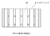
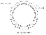
- a groove 16 is provided on the outer peripheral surface of the rider ring 3 along the direction in which the piston 2 reciprocates, and the piston 2 can reciprocate without obstructing the gas flow.
- a material for the rider ring 3 a material exhibiting high slidability in a non-lubricated state is recommended, and polytetrafluoroethylene (PTFE) or graphite is particularly preferable.
- the unlubricated state is a state in which a lubricant such as lubricating oil is not applied to the rider ring 3.
- FIG. 7 and 8 show the piston ring of the compressor described in Patent Document 2.
- FIG. This piston ring seals the gas in the cylinder as follows.
- Patent Document 2 two piston rings having different linear expansion coefficients are attached to a piston.
- a high-temperature region piston ring 21 is mounted in a groove 23 provided in the piston 2 of the reciprocating compressor for air conditioning.
- a low temperature region piston ring 22 is mounted in a groove 24 provided in the piston 2.
- the two piston rings 21 and 22 are made of materials having different linear expansion coefficients, and are designed to have different outer diameters (hereinafter referred to as free diameters) at room temperature. Therefore, the outer diameters of the two piston rings at a certain temperature are different from each other.
- the piston ring with a large free diameter and a small linear expansion coefficient is in close contact with the inner surface of the cylinder at a low temperature
- the piston ring with a small free diameter and a large linear expansion coefficient is in close contact with the inner surface of the cylinder at a high temperature. Excellent sealing performance.
- the piston ring has both a piston support function and a gas sealing function, and the piston ring is operated with the piston ring always in contact with the cylinder inner surface.
- the labyrinth seal structure an element that exhibits a support function only when the piston runout is excessive while it is normally not in contact with the cylinder is required.
- the present invention uses a rider ring that has an outer diameter that is smaller than the inner diameter of the cylinder and larger than the outer diameter of the labyrinth portion in a temperature range from the temperature at the time of starting the compressor to the temperature during operation, and the labyrinth portion is formed into the cylinder.
- An object of the present invention is to obtain a labyrinth seal structure that can be kept non-contact.
- the labyrinth seal structure according to the present invention is a labyrinth seal structure having a piston that moves up and down in a cylinder and a rider ring provided on the outer periphery of the piston, wherein the rider ring is composed of at least two rings, The linear expansion coefficients of the rings are different from each other.
- the labyrinth portion is formed using a rider ring having an outer diameter that is smaller than the inner diameter of the cylinder and larger than the outer diameter of the labyrinth portion in a temperature range from the temperature at the time of starting the compressor to the temperature during operation.
- a labyrinth seal structure that can be kept in non-contact with the cylinder is obtained.
- FIG. 1 what is indicated by reference numeral 1 is a cylinder of a reciprocating compressor (not shown).
- a piston 2 is accommodated inside the cylinder 1 so as to be movable up and down.
- the piston 2 has an upper piston disk 2a and a lower piston disk 2b.
- the lower part of the upper piston disk 2a and the upper part of the lower piston disk 2b are joined together, and the upper piston disk 2a and the lower piston disk 2b are integrated with each other.
- a second through hole 5 is formed in the upper piston disk 2a.
- a first through hole 4 is formed in the lower piston disk 2b.
- a first step portion 6 is formed below the first through hole 4.
- a second step portion 7 and a piston nut 8 are provided on the upper portion of the second through hole 5.
- the piston rod 9 inserted into the first through hole 4 from the first step portion 6 passes through the second through hole 5 and is screwed into the piston nut 8.
- the large diameter portion 9 a of the piston rod 9 is positioned in contact with the first step portion 6.
- the piston nut 8 is positioned by the second step portion 7. By tightening the piston nut 8, the piston disks 2 a and 2 b are integrally fastened as the piston 2.
- An annular recess 10 is formed on the side of the piston 2, that is, on the outer periphery.
- the annular recess 10 is formed across the piston disks 2a and 2b.
- the annular recess 10 is provided in the lower part of the upper piston disk 2a and the upper part of the lower piston disk 2b.
- a labyrinth sleeve 14 having a rider ring 3 at the top is provided in the annular recess 10.
- FIG. 1 shows the case where the rider ring 3 is provided at the upper part of the labyrinth sleeve 14, the rider ring 3 may be provided at the center or the lower part of the labyrinth sleeve 14.
- the rider ring 3 has a high linear expansion ring 12 and a low linear expansion ring 13 having a lower linear expansion coefficient than the high linear expansion ring 12.
- the high linear expansion ring 12 and the low linear expansion ring 13 are stacked along the axial direction A of the piston 2.
- a labyrinth sleeve 14 is provided below the rider ring 3.
- a labyrinth groove 15 is formed on the outer peripheral surface of the labyrinth sleeve 14.
- the labyrinth sleeve 14 and the labyrinth groove 15 are collectively referred to as a labyrinth portion 11.
- two or more rings 12 and 13 made of materials having different linear expansion coefficients are provided on the piston 2 provided with the labyrinth portion 11 so as to be in contact with each other in the vertical direction.
- the temperature of the two rings 12 and 13 can be equalized if the two rings 12 and 13 are provided in contact with each other. .
- the high linear expansion ring 12 and the low linear expansion are set so that the outer diameter of the low linear expansion ring 13 is larger than the outer diameter of the high linear expansion ring 12 in a low temperature state such as when the compressor is started.
- the dimensions and material of the ring 13 are selected.
- the high linear expansion ring 12 and the low linear expansion ring are set so that the outer diameter of the high linear expansion ring 12 is larger than the outer diameter of the low linear expansion ring 13 in a high temperature state during operation of the compressor. Thirteen dimensions and materials have been selected.
- the low linear expansion ring 13 jumps out from the labyrinth sleeve 14 and the high linear expansion ring 12 to the cylinder 1 side.
- the low linear expansion ring 13 contacts the cylinder 1 before the labyrinth sleeve 14, and the labyrinth sleeve 14 is maintained in a non-contact state with respect to the cylinder 1.
- the high linear expansion ring 12 expands and jumps out from the labyrinth sleeve 14 and the low linear expansion ring 13 to the cylinder 1 side.
- the high linear expansion ring 12 contacts the cylinder 1 before the labyrinth sleeve 14, and the labyrinth sleeve 14 is kept in a non-contact state with respect to the cylinder 1.
- the low linear expansion ring 13 is designed to have an outer diameter that is smaller than the inner diameter of the cylinder 1 in a low temperature state and larger than the outer diameter of the labyrinth portion 11. For this reason, the low linear expansion ring 13 bears the support function of the piston 2 in a low temperature state.
- the high linear expansion ring 12 is designed to have an outer diameter that is smaller than the inner diameter of the cylinder 1 in a high temperature state and larger than the outer diameter of the labyrinth portion 11. For this reason, the high linear expansion ring 12 bears the support function of the piston 2 in a high temperature state.
- the rider ring 3 Since the outer diameter of the rider ring 3 is smaller than the inner diameter of the cylinder 1 in the entire temperature range from the temperature at the time of starting the compressor to the temperature during operation, the rider ring 3 is not in the normal state. Contact. The support function of the piston 2 is manifested only when the vibration of the piston 2 is excessive at any temperature state.
- the labyrinth seal structure of this embodiment is also required to operate within the operation guarantee range of the compressor.
- the low temperature state shown in FIG. 2 is a state below the minimum temperature in the operation guarantee range of the compressor
- the high temperature state shown in FIG. 3 is a state above the maximum temperature in the operation guarantee range of the compressor.
- the labyrinth sleeve 14 contacts the inner surface of the cylinder 1 by the rider ring 3. Can be prevented.
- the first outer diameter D1 of the labyrinth portion 11 is the largest outer diameter of the labyrinth portion 11.
- the second outer diameter D2 of the rider ring 3 is the largest outer diameter of the rider ring 3.
- the gap between the labyrinth portion and the cylinder is as small as possible because the smaller the gap, the higher the sealing performance.
- the rider ring cannot protect the labyrinth portion so that the labyrinth portion does not have a larger diameter than the rider ring at low temperatures.
- the gap between the cylinder 1 and the labyrinth portion 11 can be set without being restricted by the linear expansion range of the rider ring 3. For this reason, the clearance gap between this cylinder 1 and the labyrinth part 11 can be designed very narrowly, and the sealing performance of a labyrinth seal structure can be improved.
- the labyrinth seal structure according to the present embodiment improves the support function of the piston 2 compared to the conventional labyrinth seal structure. For this reason, it is possible to reduce the rigidity of various components that have played the role of guiding the piston in a reciprocating compressor using a piston having a conventional labyrinth seal structure. As a result, the number of parts can be reduced and the assembling work can be simplified. Moreover, the vibration of the whole compressor can be reduced by lowering the overall height of the compressor as the number of parts is reduced.
- the rider ring 3 has the two rings 12 and 13 has been described.
- the rider ring 3 may be configured to have three or more rings.
- the material of the ring is selected so that the linear expansion coefficients of at least two or more rings are different from each other.
- the example in which the two rings 12 and 13 are arranged in the axial direction has been described.
- the present invention is not limited to this.
- one ring may be provided at each of the upper part, the lower part, and the middle part of the labyrinth part 11.
- the rider ring 3 is provided in the outer peripheral surface of a labyrinth part
- this invention is not limited to this.
- at least one ring may be provided at a position spaced upward or downward from the labyrinth portion 11.
- the labyrinth part can be kept in non-contact with the cylinder while performing a sealing function even in a low temperature state such as when the compressor is started and in a high temperature state during compressor operation. High performance can be maintained.
Landscapes
- Engineering & Computer Science (AREA)
- Mechanical Engineering (AREA)
- General Engineering & Computer Science (AREA)
- Compressor (AREA)
- Compressors, Vaccum Pumps And Other Relevant Systems (AREA)
Abstract
ラビリンスシール部とシリンダを非接触に保ちつつ、ピストンの側面における流体の流れを防止するラビリンスシール構造を提供する。ラビリンスシール構造は、シリンダ(1)内で上下動するピストン(2)と、ピストン(2)の外周に設けられたライダーリング(3)とを有する。ライダーリング(3)は二個以上のリング(12,13)からなり、少なくとも二個以上のリング(12,13)の線膨張率が互いに異なる。
Description
本発明は、ラビリンスシール構造に関し、特に、ガス圧縮機のピストンの側面における流体(圧縮ガス)の漏れを防止するための新規な改良に関する。
この種の従来のラビリンスシール構造としては、例えば、図4から図6で示される特許文献1や、図7および図8で示した特許文献2を挙げることができる。
図4に示したように、特許文献1のシール構造において、シリンダ1の内部にピストン2が設けられている。ピストン2には、シリンダ1の内径より小さな外径を有するライダーリング3が設けられている。ライダーリング3は、通常状態においては、シリンダ1に接触していない。しかし、ピストン2の振れがシリンダ1の内径に対して過大な場合はラビリンス部に先んじてライダーリング3がシリンダ1に接触し、ピストン2を支持する。これにより、ガスのシール機能を発揮するラビリンス部がシリンダ1の内径に対して接触しない状態を保つことが可能となる。
ピストン2の振れがシリンダ1の内径に対して過大になる場合としては、シリンダ1の内部のガスの圧力が十分に高くなっておらずラビリンスの調芯効果が得られない圧縮機起動時や、ピストンロッドが熱による曲げ変形を起こした場合などが挙げられる。
ライダーリング3の外周面には、ピストン2が往復運動する方向に沿って溝16が設けられており、ピストン2はガスの流れを阻害することなく往復運動できる。ライダーリング3の材質としては、無潤滑状態で高い摺動性を示すものが推奨され、特にポリテトラフルオロエチレン(PTFE)やグラファイトが好ましい。無潤滑状態とは、ライダーリング3に潤滑油などの潤滑剤が付与されていな状態である。
ピストン2の振れがシリンダ1の内径に対して過大になる場合としては、シリンダ1の内部のガスの圧力が十分に高くなっておらずラビリンスの調芯効果が得られない圧縮機起動時や、ピストンロッドが熱による曲げ変形を起こした場合などが挙げられる。
ライダーリング3の外周面には、ピストン2が往復運動する方向に沿って溝16が設けられており、ピストン2はガスの流れを阻害することなく往復運動できる。ライダーリング3の材質としては、無潤滑状態で高い摺動性を示すものが推奨され、特にポリテトラフルオロエチレン(PTFE)やグラファイトが好ましい。無潤滑状態とは、ライダーリング3に潤滑油などの潤滑剤が付与されていな状態である。
特許文献1のようにピストンを構成した時、圧縮機起動時の温度ではシリンダ内径より小さな外径を有するライダーリングを設置した場合であっても、運転中の温度ではライダーリングが膨張してシリンダ内面に押し付けられる寸法となり、異常な発熱と摩耗を生じる可能性がある。あるいは、運転中の温度で適切な外径となるライダーリングを設置した場合、起動時の温度でのライダーリングの外径がラビリンス部の外径より小さくなり、ラビリンス部の保護機能を発揮しない可能性がある。
これらの原因は、圧縮機起動時の温度から運転中の温度までの温度範囲におけるライダーリングの線膨張に起因する外形の変動範囲(以降、線膨張範囲と呼ぶ)と比較して、シリンダとラビリンス部との隙間が小さいことにある。一般に、PTFEをはじめとした樹脂材料は、シリンダやラビリンス部に用いられる金属材料と比較して線膨張率が大きい。加えて、ラビリンスシール構造においては、ガスの漏れ量を減らすためにシリンダとラビリンス部の隙間を可能な限り狭く設定することが求められる。以上のことから、シリンダとラビリンス部の隙間値とライダーリングの線膨張範囲のバランスをとる設計が困難である。
図7および図8は、特許文献2に記載の圧縮機のピストンリングを示している。このピストンリングは、次のようにしてシリンダ内のガスをシールしている。特許文献2において、線膨張率の異なる二個のピストンリングがピストンに装着されている。
図7および図8に示すように、特許文献2のシール構造において、空調用往復運動圧縮機のピストン2に設けられた溝23に高温領域用ピストンリング21が装着されている。ピストン2に設けられた溝24に低温領域用ピストンリング22が装着されている。二個のピストンリング21,22は、線膨張率の異なる材料で作られており、また、常温における外径(以下、自由径と呼ぶ。)が異なるよう設計されている。従って、ある温度における二個のピストンリングの外径は互いに異なるようになっている。これにより、自由径が大きく線膨張率が小さいピストンリングが低温でシリンダの内面に密着し、自由径が小さく線膨張率が大きいピストンリングが高温でシリンダの内面に密着することで、両温度域で優れたシール性を発揮する。
特許文献2の構成では、ピストンリングがピストンの支持機能とガスのシール機能を兼ねており、ピストンリングがシリンダ内面に常に接触した状態で運転を行う。これに対しラビリンスシール構造では、通常時はシリンダと非接触でありながら、ピストン振れが過大な場合にのみ支持機能を発揮する要素が求められる。
本発明は、圧縮機起動時の温度から運転中の温度までの温度範囲でシリンダの内径より小かつラビリンス部の外径より大である外径となるライダーリングを用いて、ラビリンス部をシリンダに対して非接触に保つことができるようにしたラビリンスシール構造を得ることを目的としている。
本発明によるラビリンスシール構造は、シリンダ内で上下動するピストンと、前記ピストンの外周に設けられたライダーリングとを有するラビリンスシール構造において、前記ライダーリングは二個以上のリングから成り、少なくとも二個以上の前記リングの線膨張率が互いに異なる。
本発明によれば、圧縮機起動時の温度から運転中の温度までの温度範囲でシリンダの内径より小かつラビリンス部の外径より大である外径となるライダーリングを用いて、ラビリンス部をシリンダに対して非接触に保つことができるようにしたラビリンスシール構造が得られる。
以下、図面と共に本発明によるラビリンスシール構造の好適な実施の形態について説明する。
尚、従来例と同一又は同等部分には、同一符号を付して説明する。
図1において、符号1で示されるものは、図示しない往復動圧縮機のシリンダである。このシリンダ1の内側にはピストン2が上下動自在に収容されている。
ピストン2は、上部ピストンディスク2aと下部ピストンディスク2bを有している。上部ピストンディスク2aの下部と下部ピストンディスク2bの上部が結合され、上部ピストンディスク2aと下部ピストンディスク2bは互いに一体化されている。
尚、従来例と同一又は同等部分には、同一符号を付して説明する。
図1において、符号1で示されるものは、図示しない往復動圧縮機のシリンダである。このシリンダ1の内側にはピストン2が上下動自在に収容されている。
ピストン2は、上部ピストンディスク2aと下部ピストンディスク2bを有している。上部ピストンディスク2aの下部と下部ピストンディスク2bの上部が結合され、上部ピストンディスク2aと下部ピストンディスク2bは互いに一体化されている。
上部ピストンディスク2aには第二貫通孔5が形成されている。下部ピストンディスク2bには第一貫通孔4が形成されている。第一貫通孔4の下部には第一段部6が形成されている。
第二貫通孔5の上部には第二段部7及びピストンナット8が設けられている。第一段部6から第一貫通孔4内に挿入されたピストンロッド9は、第二貫通孔5を貫通し、ピストンナット8に螺合している。
ピストンロッド9の大径部9aは第一段部6に当接して位置決めされている。ピストンナット8は第二段部7で位置決めされている。ピストンナット8を締めることによって、各ピストンディスク2a,2bがピストン2として一体に締結されている。
ピストンロッド9の大径部9aは第一段部6に当接して位置決めされている。ピストンナット8は第二段部7で位置決めされている。ピストンナット8を締めることによって、各ピストンディスク2a,2bがピストン2として一体に締結されている。
ピストン2の側部すなわち外周には、輪状凹部10が形成されている。輪状凹部10は、各ピストンディスク2a,2bを跨いで形成されている。輪状凹部10は、上部ピストンディスク2aの下部および下部ピストンディスク2bの上部に設けられている。
輪状凹部10内には、上部にライダーリング3を有するラビリンススリーブ14が設けられている。
尚、図1ではライダーリング3をラビリンススリーブ14の上部に設けた場合を示しているが、ライダーリング3をラビリンススリーブ14の中央部あるいは下部に設けてもよい。
輪状凹部10内には、上部にライダーリング3を有するラビリンススリーブ14が設けられている。
尚、図1ではライダーリング3をラビリンススリーブ14の上部に設けた場合を示しているが、ライダーリング3をラビリンススリーブ14の中央部あるいは下部に設けてもよい。
ライダーリング3は、高線膨張リング12と、この高線膨張リング12よりも低い線膨張率を有する低線膨張リング13を有している。高線膨張リング12および低線膨張リング13はピストン2の軸方向Aに沿って積層されている。
このライダーリング3の下部にはラビリンススリーブ14が設けられている。ラビリンススリーブ14の外周面にラビリンス溝15が形成されている。以降の説明において、ラビリンススリーブ14とラビリンス溝15を合わせてラビリンス部11と呼ぶ。
本実施形態のラビリンスシール構造において、ラビリンス部11を備えたピストン2に線膨張率の異なる材料からなる二個以上のリング12,13が互いに上下方向に接触した状態で設けられている。なお、ピストン上部でのみガスを圧縮する単動式の圧縮機の場合、二つのリング12,13が互いに接触した状態で設けられていると二つのリング12,13の温度を等しくすることができる。
図2に示すように、圧縮機起動時のような低温状態においては低線膨張リング13の外径が高線膨張リング12の外径より大きくなるように、高線膨張リング12と低線膨張リング13の寸法および材料が選択されている。
図3に示すように圧縮機運転中のような高温状態においては高線膨張リング12の外径が低線膨張リング13の外径より大きくなるように、高線膨張リング12と低線膨張リング13の寸法および材料が選択されている。
図3に示すように圧縮機運転中のような高温状態においては高線膨張リング12の外径が低線膨張リング13の外径より大きくなるように、高線膨張リング12と低線膨張リング13の寸法および材料が選択されている。
すると、図2に示したように低温状態においては、低線膨張リング13がラビリンススリーブ14や高線膨張リング12よりシリンダ1側に飛び出す。低線膨張リング13がラビリンススリーブ14よりも先にシリンダ1に接触し、ラビリンススリーブ14がシリンダ1に対して非接触状態に保たれる。
また、図3に示したように高温状態においては、高線膨張リング12が膨張し、ラビリンススリーブ14や低線膨張リング13よりシリンダ1側に飛び出す。高線膨張リング12がラビリンススリーブ14より先にシリンダ1に接触し、ラビリンススリーブ14がシリンダ1に対して非接触状態に保たれる。
また、図3に示したように高温状態においては、高線膨張リング12が膨張し、ラビリンススリーブ14や低線膨張リング13よりシリンダ1側に飛び出す。高線膨張リング12がラビリンススリーブ14より先にシリンダ1に接触し、ラビリンススリーブ14がシリンダ1に対して非接触状態に保たれる。
また、低線膨張リング13は、低温状態におけるシリンダ1の内径より小かつラビリンス部11の外径より大なる外径となるよう設計されている。このため、低温状態においては、低線膨張リング13がピストン2の支持機能を担う。
高線膨張リング12は、高温状態におけるシリンダ1の内径より小かつラビリンス部11の外径より大なる外径となるよう設計されている。このため、高温状態においては、高線膨張リング12がピストン2の支持機能を担う。
高線膨張リング12は、高温状態におけるシリンダ1の内径より小かつラビリンス部11の外径より大なる外径となるよう設計されている。このため、高温状態においては、高線膨張リング12がピストン2の支持機能を担う。
なお、圧縮機起動時の温度から運転中の温度までの全ての温度範囲においてライダーリング3の外径はシリンダ1の内径より小であるため、通常状態においてライダーリング3はシリンダ1に対して非接触である。ピストン2の支持機能は、いずれの温度状態であっても、ピストン2の振れが過大な場合にのみ発現する。
圧縮機は、動作保障範囲内において動作することが求められている。このため、本実施形態のラビリンスシール構造も、圧縮機の動作保障範囲内において動作することが求められる。このため、図2に示した低温状態は圧縮機の動作保障範囲の最低温度以下の状態であり、図3に示した高温状態は圧縮機の動作保障範囲の最高温度以上の状態である。
図1に示したように、ラビリンス部11の第一外径D1は、ライダーリング3の第二外径D2よりも小であるため、ライダーリング3によってラビリンススリーブ14がシリンダ1の内面へ接触することを防止できる。ラビリンス部11の第一外径D1とは、ラビリンス部11の最も大きな外径である。ライダーリング3の第二外径D2とは、ライダーリング3の最も大きな外径である。
ところで、ラビリンス部とシリンダとの隙間は、小さいほどシール性を高められるため、できるだけ小さいことが好ましい。
本発明とは異なり特許文献1の構成においては、低温時にラビリンス部がライダーリングより大径であるとライダーリングがラビリンス部を保護できないので、低温時にラビリンス部がライダーリングより大径とならないように、ラビリンス部の大きさに制約があった。このため、ラビリンス部とシリンダとの隙間を小さくすることに限界があった。
しかし本実施形態にかかるラビリンスシール構造においては、ライダーリング3の線膨張範囲の制約を受けずにシリンダ1とラビリンス部11の隙間を設定できる。このため、このシリンダ1とラビリンス部11の隙間を非常に狭く設計でき、ラビリンスシール構造のシール性を高めることができる。
本発明とは異なり特許文献1の構成においては、低温時にラビリンス部がライダーリングより大径であるとライダーリングがラビリンス部を保護できないので、低温時にラビリンス部がライダーリングより大径とならないように、ラビリンス部の大きさに制約があった。このため、ラビリンス部とシリンダとの隙間を小さくすることに限界があった。
しかし本実施形態にかかるラビリンスシール構造においては、ライダーリング3の線膨張範囲の制約を受けずにシリンダ1とラビリンス部11の隙間を設定できる。このため、このシリンダ1とラビリンス部11の隙間を非常に狭く設計でき、ラビリンスシール構造のシール性を高めることができる。
さらに、本実施形態にかかるラビリンスシール構造においては、温度に応じて異なるリング12,13がシリンダ1の内面に接触する。つまり、リング12,13一個当たりのシリンダ1の内面に対する接触頻度が減少するので、リング12,13が摩耗しにくく、ラビリンスシール構造が長寿命化する。
さらに、本実施形態にかかるラビリンスシール構造は、従来のラビリンスシール構造に比べてピストン2の支持機能が向上する。このため、従来のラビリンスシール構造のピストンを使用する往復動圧縮機においてピストンをガイドする役割を果たしていた種々の部品の剛性を下げることが可能となる。これにより、部品数の削減はもちろん、組立作業を簡略化できる。また、部品数の削減に伴って圧縮機の全高を低くすることで、圧縮機全体の振動を低減できる。
なお、上述した実施形態においては、ライダーリング3が2つのリング12,13を有する例を説明したが、ライダーリング3は3つ以上のリングを有するように構成してもよい。その際に、少なくとも2以上のリングの線膨張率が互いに異なるようにリングの材料を選択する。
また、上述した実施形態においては、2つのリング12,13を軸方向に並べて設けた例を説明したが、本発明はこれに限られない。例えば、ラビリンス部11の上部と下部と中部にそれぞれ一つずつリングを設けるようにしてもよい。
あるいは、上述した実施形態においては、ライダーリング3がラビリンス部の外周面に設けられる例を説明したが、本発明はこれに限られない。例えば、ラビリンス部11から上方あるいは下方に離間した位置にリングの少なくとも一つを設けてもよい。
また、上述した実施形態においては、2つのリング12,13を軸方向に並べて設けた例を説明したが、本発明はこれに限られない。例えば、ラビリンス部11の上部と下部と中部にそれぞれ一つずつリングを設けるようにしてもよい。
あるいは、上述した実施形態においては、ライダーリング3がラビリンス部の外周面に設けられる例を説明したが、本発明はこれに限られない。例えば、ラビリンス部11から上方あるいは下方に離間した位置にリングの少なくとも一つを設けてもよい。
本出願は、2016年5月16日出願の日本特許出願(特願2016-097801)に基づくものであり、その内容はここに参照として取り込まれる。
本発明によるラビリンスシール構造によれば、圧縮機起動時のような低温状態及び圧縮機運転中の高温状態でもシール機能を奏しつつ、シリンダに対するラビリンス部の非接触を保つことができ、圧縮機を高性能に維持することができる。
1 シリンダ
2 ピストン
2a 上部ピストンディスク
2b 下部ピストンディスク
3 ライダーリング
4 第一貫通孔
5 第二貫通孔
6 第一段部
7 第二段部
8 ピストンナット
9 ピストンロッド
9a 大径部
10 輪状凹部
11 ラビリンス部
12 高線膨張リング
13 低線膨張リング
14 ラビリンススリーブ
15 ラビリンス溝
16 ガス通過溝
2 ピストン
2a 上部ピストンディスク
2b 下部ピストンディスク
3 ライダーリング
4 第一貫通孔
5 第二貫通孔
6 第一段部
7 第二段部
8 ピストンナット
9 ピストンロッド
9a 大径部
10 輪状凹部
11 ラビリンス部
12 高線膨張リング
13 低線膨張リング
14 ラビリンススリーブ
15 ラビリンス溝
16 ガス通過溝
Claims (2)
- シリンダ内で上下動するピストンと、前記ピストンの外周に設けられたライダーリングとを有するラビリンスシール構造において、
前記ライダーリングは二個以上のリングからなり、少なくとも二個以上の前記リングの線膨張率が互いに異なる、ラビリンスシール構造。 - 前記ピストンの外周にラビリンス部が設けられており、
前記ラビリンス部の第一外径は、前記ライダーリングの第二外径よりも小さい、請求項1記載のラビリンスシール構造。
Applications Claiming Priority (2)
| Application Number | Priority Date | Filing Date | Title |
|---|---|---|---|
| JP2016097801A JP2017206964A (ja) | 2016-05-16 | 2016-05-16 | ラビリンスシール構造 |
| JP2016-097801 | 2016-05-16 |
Publications (1)
| Publication Number | Publication Date |
|---|---|
| WO2017199910A1 true WO2017199910A1 (ja) | 2017-11-23 |
Family
ID=60325146
Family Applications (1)
| Application Number | Title | Priority Date | Filing Date |
|---|---|---|---|
| PCT/JP2017/018202 Ceased WO2017199910A1 (ja) | 2016-05-16 | 2017-05-15 | ラビリンスシール構造 |
Country Status (2)
| Country | Link |
|---|---|
| JP (1) | JP2017206964A (ja) |
| WO (1) | WO2017199910A1 (ja) |
Cited By (1)
| Publication number | Priority date | Publication date | Assignee | Title |
|---|---|---|---|---|
| CN113252297A (zh) * | 2021-05-07 | 2021-08-13 | 沈阳工业大学 | 一种轴向可调式迷宫密封实验的测试装置 |
Citations (2)
| Publication number | Priority date | Publication date | Assignee | Title |
|---|---|---|---|---|
| US3653303A (en) * | 1969-04-24 | 1972-04-04 | Sulzer Ag | Guide means for a piston in a cylinder |
| JP2003097442A (ja) * | 2001-09-21 | 2003-04-03 | Sanden Corp | 空調用往復動圧縮機 |
-
2016
- 2016-05-16 JP JP2016097801A patent/JP2017206964A/ja active Pending
-
2017
- 2017-05-15 WO PCT/JP2017/018202 patent/WO2017199910A1/ja not_active Ceased
Patent Citations (2)
| Publication number | Priority date | Publication date | Assignee | Title |
|---|---|---|---|---|
| US3653303A (en) * | 1969-04-24 | 1972-04-04 | Sulzer Ag | Guide means for a piston in a cylinder |
| JP2003097442A (ja) * | 2001-09-21 | 2003-04-03 | Sanden Corp | 空調用往復動圧縮機 |
Cited By (2)
| Publication number | Priority date | Publication date | Assignee | Title |
|---|---|---|---|---|
| CN113252297A (zh) * | 2021-05-07 | 2021-08-13 | 沈阳工业大学 | 一种轴向可调式迷宫密封实验的测试装置 |
| CN113252297B (zh) * | 2021-05-07 | 2022-07-08 | 沈阳工业大学 | 一种轴向可调式迷宫密封实验的测试装置 |
Also Published As
| Publication number | Publication date |
|---|---|
| JP2017206964A (ja) | 2017-11-24 |
Similar Documents
| Publication | Publication Date | Title |
|---|---|---|
| EP3517807B1 (en) | Single seal ring stuffing box | |
| JP5636613B2 (ja) | 流体圧機器 | |
| EP2538090B1 (en) | Fluid pressure cylinder | |
| JP6017738B1 (ja) | 密封装置 | |
| JP2013530333A (ja) | ブラシリングシール | |
| JP5310666B2 (ja) | ロッキングピストンのシール構造 | |
| WO2017199910A1 (ja) | ラビリンスシール構造 | |
| WO2018180307A1 (ja) | シール材の配置構造 | |
| JP2017190772A (ja) | ピストン圧縮機用弁ユニット及びピストン圧縮機 | |
| JP5138498B2 (ja) | 往復動式圧縮機用ピストン | |
| JP2010112324A (ja) | 内燃機関のピストン | |
| JP4218421B2 (ja) | 高圧ガス圧縮機 | |
| JP2006522908A (ja) | ガススプリング | |
| US9835039B2 (en) | Slide ring seal | |
| JP5015681B2 (ja) | バンドリング | |
| JP7203971B2 (ja) | 密封装置 | |
| JP5833867B2 (ja) | ピストン | |
| JP2017180482A (ja) | 密封装置 | |
| JP5637267B2 (ja) | ロッキングピストンのシール構造 | |
| KR100890601B1 (ko) | 유압엑츄에이터 부싱 | |
| JP5527465B2 (ja) | ロッキングピストンのシール構造 | |
| JP5527464B2 (ja) | ロッキングピストンのシール構造 | |
| JP2006009928A (ja) | 密封装置 | |
| JP2008196537A (ja) | 密封構造 | |
| JP2019127835A (ja) | 内燃機関のピストン |
Legal Events
| Date | Code | Title | Description |
|---|---|---|---|
| NENP | Non-entry into the national phase |
Ref country code: DE |
|
| 121 | Ep: the epo has been informed by wipo that ep was designated in this application |
Ref document number: 17799334 Country of ref document: EP Kind code of ref document: A1 |
|
| 122 | Ep: pct application non-entry in european phase |
Ref document number: 17799334 Country of ref document: EP Kind code of ref document: A1 |