WO2017199814A1 - 電磁シールド部材、配線モジュール及び電磁シールド部材の製造方法 - Google Patents
電磁シールド部材、配線モジュール及び電磁シールド部材の製造方法 Download PDFInfo
- Publication number
- WO2017199814A1 WO2017199814A1 PCT/JP2017/017686 JP2017017686W WO2017199814A1 WO 2017199814 A1 WO2017199814 A1 WO 2017199814A1 JP 2017017686 W JP2017017686 W JP 2017017686W WO 2017199814 A1 WO2017199814 A1 WO 2017199814A1
- Authority
- WO
- WIPO (PCT)
- Prior art keywords
- cylindrical
- conductive member
- peripheral surface
- electromagnetic shielding
- cylindrical conductive
- Prior art date
- Legal status (The legal status is an assumption and is not a legal conclusion. Google has not performed a legal analysis and makes no representation as to the accuracy of the status listed.)
- Ceased
Links
Images


Classifications
-
- H—ELECTRICITY
- H01—ELECTRIC ELEMENTS
- H01B—CABLES; CONDUCTORS; INSULATORS; SELECTION OF MATERIALS FOR THEIR CONDUCTIVE, INSULATING OR DIELECTRIC PROPERTIES
- H01B7/00—Insulated conductors or cables characterised by their form
- H01B7/17—Protection against damage caused by external factors, e.g. sheaths or armouring
- H01B7/18—Protection against damage caused by wear, mechanical force or pressure; Sheaths; Armouring
- H01B7/20—Metal tubes, e.g. lead sheaths
-
- H—ELECTRICITY
- H01—ELECTRIC ELEMENTS
- H01R—ELECTRICALLY-CONDUCTIVE CONNECTIONS; STRUCTURAL ASSOCIATIONS OF A PLURALITY OF MUTUALLY-INSULATED ELECTRICAL CONNECTING ELEMENTS; COUPLING DEVICES; CURRENT COLLECTORS
- H01R13/00—Details of coupling devices of the kinds covered by groups H01R12/70 or H01R24/00 - H01R33/00
- H01R13/648—Protective earth or shield arrangements on coupling devices, e.g. anti-static shielding
- H01R13/658—High frequency shielding arrangements, e.g. against EMI [Electro-Magnetic Interference] or EMP [Electro-Magnetic Pulse]
- H01R13/6591—Specific features or arrangements of connection of shield to conductive members
-
- H—ELECTRICITY
- H01—ELECTRIC ELEMENTS
- H01B—CABLES; CONDUCTORS; INSULATORS; SELECTION OF MATERIALS FOR THEIR CONDUCTIVE, INSULATING OR DIELECTRIC PROPERTIES
- H01B13/00—Apparatus or processes specially adapted for manufacturing conductors or cables
- H01B13/22—Sheathing; Armouring; Screening; Applying other protective layers
-
- H—ELECTRICITY
- H01—ELECTRIC ELEMENTS
- H01R—ELECTRICALLY-CONDUCTIVE CONNECTIONS; STRUCTURAL ASSOCIATIONS OF A PLURALITY OF MUTUALLY-INSULATED ELECTRICAL CONNECTING ELEMENTS; COUPLING DEVICES; CURRENT COLLECTORS
- H01R43/00—Apparatus or processes specially adapted for manufacturing, assembling, maintaining, or repairing of line connectors or current collectors or for joining electric conductors
- H01R43/02—Apparatus or processes specially adapted for manufacturing, assembling, maintaining, or repairing of line connectors or current collectors or for joining electric conductors for soldered or welded connections
-
- H—ELECTRICITY
- H02—GENERATION; CONVERSION OR DISTRIBUTION OF ELECTRIC POWER
- H02G—INSTALLATION OF ELECTRIC CABLES OR LINES, OR OF COMBINED OPTICAL AND ELECTRIC CABLES OR LINES
- H02G1/00—Methods or apparatus specially adapted for installing, maintaining, repairing or dismantling electric cables or lines
- H02G1/14—Methods or apparatus specially adapted for installing, maintaining, repairing or dismantling electric cables or lines for joining or terminating cables
-
- H—ELECTRICITY
- H02—GENERATION; CONVERSION OR DISTRIBUTION OF ELECTRIC POWER
- H02G—INSTALLATION OF ELECTRIC CABLES OR LINES, OR OF COMBINED OPTICAL AND ELECTRIC CABLES OR LINES
- H02G3/00—Installations of electric cables or lines or protective tubing therefor in or on buildings, equivalent structures or vehicles
- H02G3/02—Details
- H02G3/04—Protective tubing or conduits, e.g. cable ladders or cable troughs
-
- H—ELECTRICITY
- H05—ELECTRIC TECHNIQUES NOT OTHERWISE PROVIDED FOR
- H05K—PRINTED CIRCUITS; CASINGS OR CONSTRUCTIONAL DETAILS OF ELECTRIC APPARATUS; MANUFACTURE OF ASSEMBLAGES OF ELECTRICAL COMPONENTS
- H05K9/00—Screening of apparatus or components against electric or magnetic fields
-
- H—ELECTRICITY
- H05—ELECTRIC TECHNIQUES NOT OTHERWISE PROVIDED FOR
- H05K—PRINTED CIRCUITS; CASINGS OR CONSTRUCTIONAL DETAILS OF ELECTRIC APPARATUS; MANUFACTURE OF ASSEMBLAGES OF ELECTRICAL COMPONENTS
- H05K9/00—Screening of apparatus or components against electric or magnetic fields
- H05K9/0073—Shielding materials
- H05K9/0081—Electromagnetic shielding materials, e.g. EMI, RFI shielding
-
- H—ELECTRICITY
- H05—ELECTRIC TECHNIQUES NOT OTHERWISE PROVIDED FOR
- H05K—PRINTED CIRCUITS; CASINGS OR CONSTRUCTIONAL DETAILS OF ELECTRIC APPARATUS; MANUFACTURE OF ASSEMBLAGES OF ELECTRICAL COMPONENTS
- H05K9/00—Screening of apparatus or components against electric or magnetic fields
- H05K9/0073—Shielding materials
- H05K9/0098—Shielding materials for shielding electrical cables
-
- H—ELECTRICITY
- H01—ELECTRIC ELEMENTS
- H01R—ELECTRICALLY-CONDUCTIVE CONNECTIONS; STRUCTURAL ASSOCIATIONS OF A PLURALITY OF MUTUALLY-INSULATED ELECTRICAL CONNECTING ELEMENTS; COUPLING DEVICES; CURRENT COLLECTORS
- H01R2201/00—Connectors or connections adapted for particular applications
- H01R2201/26—Connectors or connections adapted for particular applications for vehicles
-
- H—ELECTRICITY
- H01—ELECTRIC ELEMENTS
- H01R—ELECTRICALLY-CONDUCTIVE CONNECTIONS; STRUCTURAL ASSOCIATIONS OF A PLURALITY OF MUTUALLY-INSULATED ELECTRICAL CONNECTING ELEMENTS; COUPLING DEVICES; CURRENT COLLECTORS
- H01R4/00—Electrically-conductive connections between two or more conductive members in direct contact, i.e. touching one another; Means for effecting or maintaining such contact; Electrically-conductive connections having two or more spaced connecting locations for conductors and using contact members penetrating insulation
- H01R4/02—Soldered or welded connections
-
- H—ELECTRICITY
- H01—ELECTRIC ELEMENTS
- H01R—ELECTRICALLY-CONDUCTIVE CONNECTIONS; STRUCTURAL ASSOCIATIONS OF A PLURALITY OF MUTUALLY-INSULATED ELECTRICAL CONNECTING ELEMENTS; COUPLING DEVICES; CURRENT COLLECTORS
- H01R4/00—Electrically-conductive connections between two or more conductive members in direct contact, i.e. touching one another; Means for effecting or maintaining such contact; Electrically-conductive connections having two or more spaced connecting locations for conductors and using contact members penetrating insulation
- H01R4/58—Electrically-conductive connections between two or more conductive members in direct contact, i.e. touching one another; Means for effecting or maintaining such contact; Electrically-conductive connections having two or more spaced connecting locations for conductors and using contact members penetrating insulation characterised by the form or material of the contacting members
- H01R4/62—Connections between conductors of different materials; Connections between or with aluminium or steel-core aluminium conductors
- H01R4/625—Soldered or welded connections
Definitions
- This invention relates to a technique for shielding electromagnetic noise.
- Patent Document 1 a metal pipe, a cylindrical flexible shield member connected to the end of the pipe, and a ring around the pipe in a configuration in which the flexible shield member is sandwiched together with the peripheral wall of the pipe.
- a shield conductive path is disclosed that includes an annular fixture secured to the frame.
- the braid is formed by knitting a plurality of thin strands, it is easy to bend and it is difficult to keep the braid pressed against the pipe. Also, the molten brazing material tends to spread around. For this reason, it is difficult to braze the braid around the pipe.
- an object of the present invention is to make it possible to easily braze a cylindrical conductive member formed into a cylindrical shape by knitting a metal wire to the cylindrical portion.
- an electromagnetic shielding member includes a metal member having a cylindrical portion, a metal wire knitted into a cylindrical shape, and an end portion thereof on the outer peripheral surface side of the cylindrical portion Alternatively, the cylindrical conductive member disposed on the inner peripheral surface side, the pressing member that presses the cylindrical conductive member against the outer peripheral surface or the inner peripheral surface of the cylindrical portion, and the filler material melts and solidifies. A tubular conductive member is joined to the tubular portion.
- a 2nd aspect is an electromagnetic shielding member which concerns on a 1st aspect, Comprising:
- the said pressing member makes the said cylindrical conductive member the outer peripheral surface or inner peripheral surface of the said cylinder part in the whole circumferential direction of the said cylinder part.
- the ring member is pressed, and the joint extends along the circumferential direction of the ring member.
- a 3rd aspect is an electromagnetic shielding member which concerns on a 1st or 2nd aspect, Comprising: At least one of the said cylinder part and the said cylindrical conductive member is formed with aluminum or aluminum alloy. .
- the fourth aspect is an electromagnetic shield member according to the third aspect, wherein both the cylindrical portion and the cylindrical conductive member are formed of aluminum or an aluminum alloy.
- a 5th aspect is an electromagnetic shielding member which concerns on a 3rd or 4th aspect, Comprising: The said junction part melt
- a sixth aspect is an electromagnetic shielding member according to any one of the third to fifth aspects, wherein the pressing member is formed of aluminum or an aluminum alloy.
- a seventh aspect is the electromagnetic shielding member according to any one of the first to sixth aspects, wherein the joining portion is interposed between the tubular portion and the pressing member, and the tubular conductive member. Is in a state of being joined to the cylindrical portion.
- An eighth aspect is the electromagnetic shielding member according to any one of the first to seventh aspects, wherein the pressing member is provided at a plurality of locations at intervals along the axial direction of the cylindrical portion, A joining part exists between the said pressing members provided in multiple places, and is a state which joins the said cylindrical conductive member to the said cylinder part.
- a wiring module includes at least one linear conductor and an electromagnetic shielding member according to any one of first to eighth that electromagnetically shields the linear conductor.
- a manufacturing method of an electromagnetic shielding member includes (a) a metal wire knitted on the outer peripheral surface side or the inner peripheral surface side of the cylindrical portion of the metal member having a cylindrical portion.
- the eleventh aspect is a method of manufacturing an electromagnetic shield member according to the tenth aspect, wherein the melted material melted between the cylindrical portion and the pressing member in the step (d), By solidifying between them, the tubular conductive member is joined to the tubular portion.
- a twelfth aspect is a method of manufacturing an electromagnetic shield member according to the tenth or eleventh aspect, and in the step (b), a plurality of the pressing members are spaced along the axial direction of the cylindrical portion.
- the filler material is disposed at a position between the pressing members provided at a plurality of locations, and the melted melt material is provided at a plurality of locations in the step (d).
- the cylindrical conductive member is solidified in a state of being held between the pressing members provided on the cylindrical member, and the cylindrical conductive member is joined to the cylindrical portion.
- brazing can be performed with the pressing member pressing the cylindrical conductive member against the outer peripheral surface or inner peripheral surface of the cylindrical portion. Further, since the melted filler material joins the cylindrical conductive member to the cylindrical portion, it is difficult to spread around. For this reason, the cylindrical conductive member formed into a cylindrical shape by knitting a metal wire can be easily brazed to the cylindrical portion.
- the pressing member can perform brazing while the cylindrical conductive member is pressed against the outer peripheral surface or the inner peripheral surface of the cylindrical portion over the entire circumferential direction of the cylindrical portion.
- the tubular conductive member can be joined to the outer periphery of the tubular portion by the joining portion extending in the entire circumferential direction of the ring member.
- the oxide film on the surface of the cylindrical portion and the cylindrical conductive member formed of aluminum or aluminum alloy is destroyed or removed when brazing, and the cylindrical conductive member is brazed into the cylindrical portion. You can touch.
- both the cylindrical portion and the cylindrical conductive member are formed of aluminum or an aluminum alloy, the cylindrical portion and the cylindrical conductive member are satisfactorily brazed while reducing the weight. it can.
- An aluminum alloy containing silicon has a lower melting point than aluminum and is suitable for brazing aluminum or an aluminum alloy.
- the tubular conductive member can be easily joined to the tubular portion using such an alloy as a filler material.
- the joint portion is also well attached to the pressing member. For this reason, a pressing member can also be joined favorably.
- the cylindrical conductive member can be reliably joined to the cylindrical portion inside the pressing member.
- the eighth aspect it is possible to keep the filler material melted between the plurality of pressing members and to join the cylindrical conductive member to the cylindrical portion at that portion.
- brazing can be performed with the pressing member pressing the cylindrical conductive member against the outer peripheral surface or inner peripheral surface of the cylindrical portion. Further, since the melted filler material joins the cylindrical conductive member to the cylindrical portion, it is difficult to spread around. For this reason, in a wiring module including a linear conductor and an electromagnetic shield member, a cylindrical conductive member formed in a cylindrical shape by knitting a metal wire can be easily brazed to the cylindrical portion.
- brazing can be performed in a state where the cylindrical conductive member is pressed against the outer peripheral surface or inner peripheral surface of the cylindrical portion with the pressing member. Further, since the melted filler material joins the cylindrical conductive member to the cylindrical portion, it is difficult to spread around. For this reason, the cylindrical conductive member formed into a cylindrical shape by knitting a metal wire can be easily brazed to the cylindrical portion.
- the cylindrical conductive member can be reliably joined to the cylindrical portion inside the pressing member.
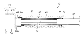
- FIG. 1 is a schematic cross-sectional view showing the wiring module 10.
- the wiring module 10 includes a plurality of covered electric wires 12 as at least one linear conductor, a connector 20 as an end part attached to one end of the plurality of covered electric wires 12, an electromagnetic shield member 30, and an external protection. Member 26.
- the plurality of covered electric wires 12 are bundled into one here.
- the covered electric wire 12 includes a core wire and a covering that covers the periphery of the core wire.
- the core wire is a linear member made of metal such as copper, copper alloy, aluminum, or aluminum alloy.
- the core wire may have a configuration in which a plurality of strands are twisted together, or may be configured by a single wire.
- the coating is an insulating member formed of resin or the like, and is formed so as to cover the core wire by extrusion coating or the like.
- the covered electric wire 12 may be only one.
- it is not essential that the covered electric wire 12 is used as the linear conductive wire, and a bare conductor that is not covered around may be used. In this case, the bare conductor may be covered with a heat shrinkable tube or the like.
- a connector 20 is attached to the tip of the plurality of covered electric wires 12.
- the connector 20 is a member formed of an insulating material such as resin.
- the connector 20 includes a housing main body 21a whose outer peripheral surface has a rectangular parallelepiped outer peripheral surface shape, and a connecting portion 21b connected to one end of the housing main body 21a (the end on the side to which the covered electric wire 12 is connected). Is provided.
- the connecting portion 21b is formed in a shape (here, a rectangular parallelepiped shape) that is thinner than the housing main body portion 21a.
- the terminal portion corresponding to each covered electric wire 12 is incorporated in the housing portion 21.
- Each terminal portion is connected to the core wire of the covered electric wire 12.
- Each terminal part and the core wire are connected by ultrasonic welding, resistance welding, soldering, crimping, or the like.
- this terminal portion is embedded in the housing portion 21 by insert molding or the like in a state where the connecting portion with the conductor of the covered electric wire 12 is embedded in the housing portion 21 and the connecting portion on the opposite side is projected. Yes.
- the connecting portion of the terminal portion is exposed on the opposite side of the housing main body portion 21a from the connecting portion 21b.
- connection part is a part provided for connection to the external electrical component side, and is a round terminal shape with a screw hole, a cylindrical female terminal shape, or a pin shape or tab shape. It is formed in a male terminal shape or the like.
- the covered electric wire 12 including the core wire connected to the terminal portion extends outward from the connecting portion 21 b side of the housing portion 21.
- the connector 20 is connected to various electrical components mounted on the vehicle, and the covered electric wire 12 is electrically connected to the electrical components.
- the electromagnetic shield member 30 includes a metal pipe 32 and a metal shell 36 as metal members, a cylindrical conductive member 40 constituted by a metal wire 40a, and ring members 50 and 60.
- a metal pipe 32 is connected to one end of the cylindrical conductive member 40
- a metal shell 36 is connected to the other end of the cylindrical conductive member 40.
- the metal shell 36 covers the outer periphery of the connector 20, and the cylindrical conductive member 40 and the metal pipe 32 cover the covered electric wire 12 extending from the connector 20.
- this electromagnetic shielding member 30 electromagnetically shields between the electric path
- the ring member 50 is provided at a connecting portion between the cylindrical conductive member 40 and the metal pipe 32, and the ring member 60 is used at a connecting portion between the cylindrical conductive member 40 and the metal shell 36.
- the electromagnetic shielding member 30 includes both the metal pipe 32 and the metal shell 36. Even when the electromagnetic shield member 30 includes both the metal pipe 32 and the metal shell 36, the connecting portion between the cylindrical conductive member 40 and the metal pipe 32, the cylindrical conductive member 40, and the metal shell 36. It is not necessary to apply the connection configuration using the ring members 50 and 60 to both of the connection portions.
- the metal shell 36 is a member formed by press-molding a metal plate such as aluminum, aluminum alloy, copper, copper alloy, stainless steel, or iron, and the periphery of the housing main body 21a and the connecting portion 21b of the connector 20 It is formed in a box shape covering.
- the metal shell 36 is opened on the outward side of the connecting portion 21b and on the opposite side.
- the cylindrical part 36b surrounding the connecting part 21b in the metal shell 36 covers the end part of the covered electric wire 12 on the side connected to the terminal.
- the metal shell 36 is an example of a metal member having a cylindrical portion 36b.
- the metal pipe 32 is a member formed in a cylindrical shape in which the covered electric wire 12 can be disposed.
- the metal pipe 32 is a metal member formed of a metal such as aluminum, stainless steel, or iron.
- the metal pipe 32 has a role of covering and protecting a portion of the covered electric wire 12 away from the connector 20 and a role of performing electromagnetic shielding. Since the entire extending direction of the metal pipe 32 has a cylindrical shape, the metal pipe 32 is a kind of metal member having a cylindrical portion.
- the metal pipe 32 may be a cylinder formed by combining semi-cylindrical members.
- An insulating coating layer may be formed on the outer periphery of the metal pipe 32. The insulating coating layer can be formed by thermally shrinking the heat-shrinkable tube or applying an insulating paint. But it is preferable that the insulation coating layer is formed except the location where the cylindrical conductive member 40 is connected among the metal pipes 32.
- the reason why the metal pipe 32 is provided at a position spaced from the connector 20 is to allow the covered electric wire 12 to be bent between the metal pipe 32 and the connector 20. That is, since the metal pipe 32 is a relatively hard member, it also serves to maintain the covered wire 12 in a predetermined path shape. However, if the entire covered electric wire 12 is not bent, it is difficult to assemble the wiring module 10 in the vehicle. Then, while fixing the metal pipe 32 to a vehicle and making the connector 20 easy to bend in a state where the connector 20 is connected to an electric part of the vehicle, their workability can be improved.
- the cylindrical conductive member 40 is a member formed into a cylindrical shape by knitting a metal wire 40a.
- the cylindrical conductive member 40 is, for example, a braid in which metal wires are knitted in a cylindrical shape, a metal cloth having a mesh structure woven so that metal wires intersect vertically and horizontally, or a metal mesh is rounded so as to form a cylinder shape. It is assumed that the configuration is the same.
- the end of one side of the cylindrical conductive member 40 is covered with the end of the metal pipe 32.
- a ring member 50 is provided on the outer periphery of the portion of the cylindrical conductive member 40 that is covered with the metal pipe 32.
- the filler material described later is melted and solidified, so that a joining portion 54 that is preferably in contact with the metal pipe 32 and the ring member 50 and joins the cylindrical conductive member 40 to the metal pipe 32 is formed.
- the other end portion of the cylindrical conductive member 40 is covered with the cylindrical portion 36 b of the metal shell 36.
- the ring member 60 is provided in the outer periphery of the part covered on the cylinder part 36b among the cylindrical conductive members 40.
- a joining portion 64 is formed by melting and solidifying the filler material described later, preferably in contact with the tubular portion 36b and the ring member 50 and joining the tubular conductive member 40 to the tubular portion 36b.
- a joining portion 64 is formed by melting and solidifying the filler material described later, preferably in contact with the tubular portion 36b and the ring member 50 and joining the tubular conductive member 40 to the tubular portion 36b.
- the external protection member 26 covers a portion of the covered electric wire 12 between the connector 20 and the metal pipe 32.
- a bendable member such as a corrugated tube is preferably used.
- connection portion between the metal pipe 32 and the cylindrical conductive member 40 will be described more specifically.
- connection part of the cylindrical part 36b of the metal shell 36 and the cylindrical conductive member 40 is the same as the structure regarding the connection part of the metal pipe 32 and the cylindrical conductive member 40. Description will be made centering on the configuration of the connecting portion with the metal pipe 32.
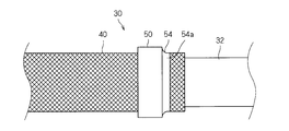
- FIG. 2 is a side view showing a connecting portion between the metal pipe 32 and the cylindrical conductive member 40
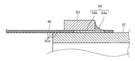
- FIG. 3 is a partial cross-sectional view showing a connecting portion between the metal pipe 32 and the cylindrical conductive member 40.
- the ring member 50 is a short cylindrical member.
- the ring member 50 is a metal member formed of aluminum, an aluminum alloy, copper, a copper alloy, or the like.
- the inner diameter dimension of the ring member 50 is larger than the outer diameter dimension of the metal pipe 32, and is set to a size that allows the cylindrical conductive member 40 to be sandwiched between the ring member 50 and the metal pipe 32. For this reason, the ring member 50 presses the cylindrical conductive member 40 against the outer peripheral surface of the metal pipe 32 in the entire circumferential direction of the metal pipe 32.
- the joining portion 54 is preferably in contact with the metal pipe 32 and the ring member 50 to join the cylindrical conductive member 40 to the metal pipe 32. More specifically, the joint portion 54 is provided at a first corner provided between an end surface of the ring member 50 and a portion of the outer peripheral surface of the metal pipe 32 facing the one end surface of the ring member 50. It includes a joint 54 a and a second joint 54 b interposed between the inner peripheral surface of the ring member 50 and the outer peripheral surface of the metal pipe 32.
- the fact that a certain object is interposed between two other objects means that the certain object exists between two other objects. Therefore, the second joint portion 54b is formed inside the ring member 50. It exists between the peripheral surface and the outer peripheral surface of the metal pipe 32.
- the first joint portion 54a extends along the circumferential direction of one end surface of the ring member 50, and joins the cylindrical conductive member 40 to the outer circumferential surface of the metal pipe 32 in the entire circumferential direction.
- the second joint portion 54 b extends along the circumferential direction of the inner circumferential surface of the ring member 50, and a portion of the cylindrical conductive member 40 located on the inner circumferential side of the ring member 50 is the outer circumference of the metal pipe 32. Bonded to the surface. For this reason, the cylindrical conductive member 40 is joined to the outer peripheral surface of the metal pipe 32 by the joint portion 54 at positions outside the inner peripheral surface and one end surface of the ring member 50.
- the joint portion may be partially formed in the circumferential direction of the ring member 50.
- the joint portion may include only one of the first joint portion 54a and the second joint portion 54b.
- the joint 54 is joined to the surface of the metal wire 40 a in a state of enclosing the metal wire 40 a of the cylindrical conductive member 40 and to the surface of the metal pipe 32. For this reason, the cylindrical conductive member 40 is mechanically connected by the joint portion 54 so as not to leave the surface of the metal pipe 32.
- the joining portion 54 is formed of a metal and has conductivity, and at least one of maintaining the tubular conductive member 40 in contact with the metal pipe 32, the tubular conductive member 40. Is electrically connected to the metal pipe 32.
- the surface of the metal pipe 32 and the cylindrical conductive member 40 formed of aluminum or an aluminum alloy is oxidized. A film is formed. This oxide film prevents electrical connection between the metal pipe 32 and the cylindrical conductive member 40. Therefore, as described above, when the metal pipe 32 and the cylindrical conductive member 40 are joined at the joint portion 54 formed by melting the filler material, the oxide film is destroyed or removed when the filler material is melted. . For this reason, at least one of the metal pipe 32 and the cylindrical conductive member 40 is formed of aluminum or an aluminum alloy to reduce the weight, and the metal pipe 32 and the cylindrical conductive member 40 are electrically connected favorably. be able to.
- both the metal pipe 32 and the cylindrical conductive member 40 are formed of aluminum or an aluminum alloy, the oxide films on both surfaces of the metal pipe 32 and the cylindrical conductive member 40 are reduced while further reducing the weight. They can be destroyed or removed and connected well. Moreover, dissimilar metal contact corrosion between the metal pipe 32 and the cylindrical conductive member 40 can be suppressed.
- the filler material it is preferable to select a filler material having good wettability with respect to the metal pipe 32, the cylindrical conductive member 40 and the ring member 50 and having a melting point lower than those.
- both the metal pipe 32 and the cylindrical conductive member 40 are formed of aluminum or an aluminum alloy
- a filler material that can be used for brazing the aluminum or aluminum alloy can be used as the filler material.
- an aluminum alloy containing silicon can be used as an example of such a filler material.
- the joining portion 54 melts and solidifies the aluminum alloy containing silicon so that the cylindrical conductive member 40 is connected to the metal pipe 32. It is formed as being in a state of being joined to.
- the melting point can be adjusted by the ratio of silicon.
- the ring member 50 a material having a melting point higher than that of the filler material and good wettability of the filler material can be used.
- a filler material that can be used for brazing the aluminum or aluminum alloy is selected. For this reason, it is preferable that the ring member 50 is formed of aluminum or an aluminum alloy.
- the metal pipe 32, the cylindrical conductive member 40, and the ring member 50 are formed of aluminum or an aluminum alloy, and the filler material is formed of an aluminum alloy (for example, an alloy containing silicon as described above).
- the filler material is formed of an aluminum alloy (for example, an alloy containing silicon as described above).
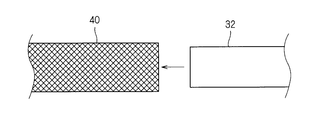
- a metal pipe 32 and a cylindrical conductive member 40 are prepared.
- the end of the metal pipe 32 is inserted into the cylindrical conductive member 40. It can also be said that the end of the cylindrical conductive member 40 is put on the outer periphery of the end of the metal pipe 32. Thereby, the edge part of the cylindrical conductive member 40 is arrange
- the ring member 50 is disposed on the outer periphery of the portion of the cylindrical conductive member 40 that is covered with the metal pipe 32. Thereby, the cylindrical conductive member 40 can be pressed against the outer peripheral surface of the metal pipe 32 (step (b)).
- the ring member 50 is fitted from the end of the cylindrical conductive member 40 opposite to the metal pipe 32, and the ring member 50 is connected to the end of the metal pipe 32 along the cylindrical conductive member 40. It is good to carry out by moving toward the outer periphery of the part. Thereby, the end of the cylindrical conductive member 40 can be sandwiched between the metal pipe 32 and the ring member 50. In this example, only one ring member 50 is used.
- the filler material 54 ⁇ / b> B is disposed at a position on the outer peripheral surface side of the metal pipe 32 and where the end of the cylindrical conductive member 40 is disposed (step (c)).
- the filler material 54B is a solder, a brazing material, or the like, and a metal having good wettability with respect to the metal pipe 32 and the cylindrical conductive member 40 and having a melting point lower than those is used.
- the filler material 54B exhibits good wettability even with respect to the ring member 50, and will be described here on the basis thereof.
- the filler material 54 ⁇ / b> B is provided, for example, in a thread form, and is disposed at the above-described location by being wound around the outer periphery of the cylindrical conductive member 40 around the metal pipe 32.
- the number of windings of the filler material 54B is preferably one or more times.
- the filler material 54 ⁇ / b> B is preferably disposed at a position in contact with or close to the end surface of the ring member 50.
- the filler material may be provided in a plate-like or granular form.
- the order of the above steps (a), (b) and (c) is arbitrary.
- the ring member 50 may be disposed at the above location.
- the operation of arranging the cylindrical conductive member 40 on the outer peripheral side of the metal pipe 32 and the ring member 50 may be provided at the above-mentioned locations.
- the filler material 54B is attached and integrated in advance with respect to the ring member 50, and the ring member 50 and the filler material 54B are attached to the outer periphery of the cylindrical conductive member 40 around the metal pipe 32 at the same time. Also good.
- the ring member and the filler material can be integrated by forming a groove in the inner periphery of the ring member and setting the filler material in the groove.
- the arrangement position of the filler material 54B is not limited to the above example.
- the filler material may be disposed on the inner peripheral side of the ring member.
- the filler material is disposed at a location different from the location where the ring member presses the cylindrical conductive member toward the outer peripheral surface of the metal pipe. Preferably it is.
- the filler material 54 ⁇ / b> B is heated and melted, and the melted filler material 54 ⁇ / b> B comes into contact with the metal pipe 32 and the ring member 50 to connect the cylindrical conductive member 40 to the metal pipe. 32 to join.
- the heating can be performed by arranging the metal pipe 32, the cylindrical conductive member 40, the metal pipe 32, and the filler material 54B in the heating furnace 70, high frequency induction heating, heating by a burner, or the like.
- the melted filler material 54 ⁇ / b> B Since the melted filler material 54 ⁇ / b> B has good wettability with respect to the metal pipe 32, the ring member 50, and the cylindrical conductive member 40, the melted filler material 54 ⁇ / b> B is directed to the end surface of the end surface of the ring member 50 and the outer peripheral surface of the metal pipe 32. When it spreads between the metal wires 40a between the mating portions and solidifies at that portion, it becomes the first joint portion 54a that joins the cylindrical conductive member 40 to the surface of the metal pipe 32.
- the melted filler material 54 ⁇ / b> B has good wettability with respect to the metal pipe 32, the ring member 50, and the cylindrical conductive member 40, and thus the inner peripheral surface of the ring member 50 and the outer peripheral surface of the metal pipe 32. Between the metal wires 40a and spreads between the metal wires 40a. Then, when the melted filler material 54B is solidified between the inner peripheral surface of the ring member 50 and the outer peripheral surface of the metal pipe 32, a second joint portion 54b that joins the cylindrical conductive member 40 to the surface of the metal pipe 32; Become.
- the filler material 54 ⁇ / b> B melts and then solidifies to become the joint portion 54, so that the cylindrical conductive member 40 is pressed against the metal pipe 32. Both states can be fixed and bonded together. Further, since the melted filler material 54B accumulates along the surface of the ring member 50 around the portion where the ring member 50 presses the cylindrical conductive member 40 and solidifies to form the joint portion 54, from this point In addition, the cylindrical conductive member 40 can be reliably joined by the metal pipe 32.
- the end of the cylindrical conductive member 40 is disposed on the outer peripheral surface of the metal pipe 32, and the cylindrical conductive member is formed by the ring member 50. Since the end of 40 is pressed against the outer peripheral surface of the metal pipe 32, brazing can be performed with the ring member 50 pressing the cylindrical conductive member 40 against the outer peripheral surface of the metal pipe 32. Further, the melted filler material 54B is in a state of joining the cylindrical conductive member 40 to the metal pipe 32 to form the joint portion 54, so that the melted melt material 54B is difficult to spread around. For this reason, the cylindrical conductive member 40 formed by knitting the metal wire 40 a can be easily brazed to the metal pipe 32.
- the joint portion 54 extends over the entire circumferential direction of the metal pipe 32.
- the cylindrical conductive member 40 can be joined to the outer periphery of the metal pipe 32 by the joining portion 54 that extends easily in the circumferential direction of the ring member 50.
- one of the metal pipe 32 and the cylindrical conductive member 40 is formed of aluminum or an aluminum alloy
- an oxide film on the surface of the metal pipe 32 or the cylindrical conductive member 40 formed of aluminum or an aluminum alloy Can be destroyed or removed when brazing, and the cylindrical conductive member 40 can be satisfactorily connected to the metal pipe 32.
- both the metal pipe 32 and the cylindrical conductive member 40 are formed of aluminum or an aluminum alloy, the cylindrical conductive member 40 can be satisfactorily connected to the metal pipe 32 while reducing the weight of the electromagnetic shield member 30. .
- an aluminum alloy containing silicon has a lower melting point than aluminum and is suitable for brazing aluminum or an aluminum alloy.
- the cylindrical conductive member 40 can be easily attached to the metal pipe 32. Can be joined.
- the filler material 54B when a material suitable for aluminum or an aluminum alloy is used as the filler material 54B, when the ring member 50 is formed of aluminum or an aluminum alloy, the ring member 50 is also satisfactorily bonded to the bonding portion 54. . For this reason, the ring member 50 also contributes to improving the connection strength between the cylindrical conductive member 40 and the cylindrical conductive member 40.
- the cylindrical conductive member 40 can be made of metal with a relatively small amount of filler material. It can be joined to the pipe 32. For example, even when there is only one ring member 50, the cylindrical conductive member 40 can be joined to the metal pipe 32 by the joint portion inside the ring member 50.
- a plurality of ring members 50 are provided at intervals along the axial direction of the metal pipe 32, and the joint portions 154 are formed of the plurality of ring members 50.
- the cylindrical conductive member 40 may be joined to the metal pipe 32 with a gap therebetween.
- the ring members 50 are provided at a plurality of locations at intervals along the axial direction of the metal pipe 32, and the filler material 154 ⁇ / b> B is disposed between the plurality of ring members 50.
- the melt material 154B is heated and melted, and the melted melt material 154B is held between the plurality of ring members 50, and the melt material 154B melted at that portion. It is good to solidify and form the junction part 154 which joins the cylindrical electrically-conductive member 40 to the metal pipe 32.
- the cylindrical conductive member 40 can be more reliably joined to the metal pipe 32 by the joining portion 154 between the plurality of ring members 50. Even in this case, a part of the joint 154 may enter between the metal pipe 32 and the ring member 50.
- the end portion of the cylindrical conductive member 40 is disposed on the inner peripheral surface side of the metal pipe 32, and the ring member 250 is fitted on the inner peripheral surface side to form a cylindrical shape.
- the joint portion 254 is in contact with the inner peripheral surface of the metal pipe 32 and the ring member 250 and the cylindrical conductive member 40 and the metal pipe 32. It may be in a state where it is joined.
- the pressing members that press the cylindrical conductive member 40 against the metal pipe 32 are the ring members 50 and 250
- the ring shape is not necessarily required.
- the pressing member may be a member that can press the cylindrical conductive member against the metal pipe at a plurality of locations around the metal pipe, and the joint may be formed between the plurality of pressing locations around the metal pipe.
- a plurality of ring members may be provided at intervals, and a joint may be formed between them, as in the modification shown in FIGS. 12 and 13.
- Electromagnetic shielding member 32 Metal pipe 36 Metal shell 36b Cylindrical part 40 Cylindrical conductive member 40a Metal wire 50, 60, 250 Ring member 54, 64, 154 Join part 54B, 154B, 254 Filler material 54a First 1 junction 54b 2nd junction
Landscapes
- Engineering & Computer Science (AREA)
- Microelectronics & Electronic Packaging (AREA)
- Manufacturing & Machinery (AREA)
- Civil Engineering (AREA)
- Electromagnetism (AREA)
- Architecture (AREA)
- Physics & Mathematics (AREA)
- Structural Engineering (AREA)
- Insulated Conductors (AREA)
- Shielding Devices Or Components To Electric Or Magnetic Fields (AREA)
- Manufacturing Of Electric Cables (AREA)
- Processing Of Terminals (AREA)
- Details Of Indoor Wiring (AREA)
Abstract
金属線が編まれて筒形状に形成された筒状導電部材を、筒部に容易にろう接できるようにすることを目的とする。電磁シールド部材は、筒部を有する金属製部材(例えば、金属パイプ)と、金属線が編まれて筒形状に形成され、その端部が筒部の外周面側又は内周面側に配設された筒状導電部材と、筒状導電部材を筒部の外周面又は内周面に押付ける押付部材(例えば、リング部材)と、溶加材が溶けて固化することで筒状導電部材を筒部に接合する状態となった接合部とを備える。
Description
この発明は、電磁ノイズを遮蔽する技術に関する。
特許文献1には、金属製のパイプと、前記パイプの端部に接続される筒状の可撓性シールド部材と、可撓性シールド部材をパイプの周壁と共に挟持する構成でパイプの周囲に環状に固定された環状固定具とを備えるシールド導電路が開示されている。
ところで、軽量化等の観点から、可撓性シールド部材等を、アルミニウム製の編組によって構成することが検討されている。この場合、アルミニウム製の部品の表面に形成された酸化膜が、編組とパイプとの良好な接続を妨げる。このような事情等から、パイプと編組とをろう接することが考えられる。
しかしながら、編組は、複数の細い素線が編まれることによって形成されているため、曲り易く、編組をパイプの周囲に押付けた状態に保つことが困難である。また、溶けたろう材が周囲に広がってしまい易い。このため、パイプの周囲に編組をろう接することが困難である。
そこで、本発明は、金属線が編まれて筒形状に形成された筒状導電部材を、筒部に容易にろう接できるようにすることを目的とする。
上記課題を解決するため、第1の態様に係る電磁シールド部材は、筒部を有する金属製部材と、金属線が編まれて筒形状に形成され、その端部が前記筒部の外周面側又は内周面側に配設された筒状導電部材と、前記筒状導電部材を前記筒部の外周面又は内周面に押付ける押付部材と、溶加材が溶けて固化することで前記筒状導電部材を前記筒部に接合する状態となった接合部とを備える。
第2の態様は、第1の態様に係る電磁シールド部材であって、前記押付部材は、前記筒部の周方向全体で、前記筒状導電部材を前記筒部の外周面又は内周面に押付けるリング部材であり、前記接合部は、前記リング部材の周方向に沿って延在しているものである。
第3の態様は、第1又は第2の態様に係る電磁シールド部材であって、前記筒部及び前記筒状導電部材のうちの少なくとも一方は、アルミニウム又はアルミニウム合金により形成されているものである。
第4の態様は、第3の態様に係る電磁シールド部材であって、前記筒部及び前記筒状導電部材のうちの両方が、アルミニウム又はアルミニウム合金により形成されているものである。
第5の態様は、第3又は第4の態様に係る電磁シールド部材であって、前記接合部は、シリコンを含むアルミニウム合金により形成された前記溶加材が溶けて固化することで前記筒状導電部材を前記筒部に接合する状態となったものである。
第6の態様は、第3から第5のいずれか1つの態様に係る電磁シールド部材であって、前記押付部材がアルミニウム又はアルミニウム合金により形成されているものである。
第7の態様は、第1から第6のいずれか1つの態様に係る電磁シールド部材であって、前記接合部は、前記筒部と前記押付部材との間に介在して前記筒状導電部材を前記筒部に接合する状態となっているものである。
第8の態様は、第1から第7のいずれか1つの態様に係る電磁シールド部材であって、前記押付部材が前記筒部の軸方向に沿って間隔をあけて複数箇所に設けられ、前記接合部は、複数箇所に設けられた前記押付部材の間に存在して前記筒状導電部材を前記筒部に接合する状態となっているものである。
第9の態様に係る配線モジュールは、少なくとも1本の線状導体と、前記線状導体を電磁シールドする第1から第8のいずれか1つに係る電磁シールド部材とを備える。
上記課題を解決するため、第10の態様に係る電磁シールド部材の製造方法は、(a)筒部を有する金属製部材の前記筒部の外周面側又は内周面側に、金属線が編まれて筒形状に形成された筒状導電部材の端部を配設する工程と、(b)前記筒部の外周面側又は内周面側に押付部材を配設し、前記筒状導電部材を前記筒部の外周面又は内周面に押付ける工程と、(c)前記筒部の外周面側又は内周面側であって前記筒状導電部材の端部が配設される箇所に、溶加材を配設する工程と、(d)前記工程(a)、(b)、(c)の後に、前記溶加材を溶かして、溶けた前記溶加材が固化することで前記筒状導電部材を前記筒部に接合する状態にする工程とを備える。
第11の態様は、第10の態様に係る電磁シールド部材の製造方法であって、前記工程(d)において、溶けた前記溶加材が前記筒部と前記押付部材との間に流れ込んで、それらの間で固化することで前記筒状導電部材を前記筒部に接合する状態にするものである。
第12の態様は、第10又は第11の態様に係る電磁シールド部材の製造方法であって、前記工程(b)において、前記押付部材を前記筒部の軸方向に沿って間隔をあけて複数箇所に設け、前記工程(c)において、前記溶加材を複数箇所に設けられる前記押付部材の間となる位置に配設し、前記工程(d)において、溶けた前記溶加材が複数箇所に設けられた押付部材の間に保たれた状態で固化して、前記筒状導電部材を前記筒部に接合するものである。
第1~第9の態様によると、押付部材で筒状導電部材を筒部の外周面又は内周面に押付けた状態でろう接を行える。また、溶けた溶加材は、筒状導電部材を前記筒部に接合するため、周囲に広がり難くなる。このため、金属線が編まれて筒形状に形成された筒状導電部材を、筒部に容易にろう接できる。
第2の態様によると、押付部材により、筒部の周方向全体で、筒状導電部材を筒部の外周面又は内周面に押付けた状態で、ろう接を行える。また、リング部材の周方向全体に延在する接合部によって、筒状導電部材を筒部の外周に接合することができる。
第3の態様によると、筒部及び筒状導電部材のうちアルミニウム又はアルミニウム合金により形成されたものの表面の酸化皮膜を、ろう接する際に破壊又は除去して、筒状導電部材を筒部にろう接できる。
第4の態様によると、筒部及び筒状導電部材のうちの両方が、アルミニウム又はアルミニウム合金により形成されているため、軽量化を図りつつ、筒部と筒状導電部材とを良好にろう接できる。
シリコンを含むアルミニウム合金は、アルミニウムより融点が低く、アルミニウム又はアルミニウム合金をろう接するの適している。第5の態様では、かかる合金を溶加材として、筒状導電部材を筒部に容易に接合できる。
第6の態様によると、溶加材としてアルミニウム又はアルミニウム合金適したものを用いると、接合部は、押付部材にも良好に付着した状態となる。このため、押付部材をも良好に接合することができる。
第7の態様によると、押付部材の内側で、筒状導電部材を筒部により確実に接合することができる。
第8の態様によると、複数の押付部材の間で溶けた溶加材を保ち、その部分で筒状導電部材を筒部に接合することができる。
第9の態様によると、押付部材で筒状導電部材を筒部の外周面又は内周面に押付けた状態でろう接を行える。また、溶けた溶加材は、筒状導電部材を前記筒部に接合するため、周囲に広がり難くなる。このため、線状導体と電磁シールド部材とを備える配線モジュールにおいて、金属線が編まれて筒形状に形成された筒状導電部材を、筒部に容易にろう接できる。
第10の態様に係る電磁シールド部材の製造方法によると、押付部材で筒状導電部材を筒部の外周面又は内周面に押付けた状態でろう接を行える。また、溶けた溶加材は、筒状導電部材を前記筒部に接合するため、周囲に広がり難くなる。このため、金属線が編まれて筒形状に形成された筒状導電部材を、筒部に容易にろう接できる。
第11の態様によると、押付部材の内側で、筒状導電部材を筒部により確実に接合することができる。
第12の態様によると、複数の押付部材の間で溶けた溶加材を保ち、その部分で筒状導電部材を筒部に接合することができる。
<全体構成について>
以下、実施形態に係る電磁シールド部材について説明する。ここでは、まず、電磁シールド部材30が適用された配線モジュール10の全体構成について説明する。図1は配線モジュール10を示す概略断面図である。
以下、実施形態に係る電磁シールド部材について説明する。ここでは、まず、電磁シールド部材30が適用された配線モジュール10の全体構成について説明する。図1は配線モジュール10を示す概略断面図である。
配線モジュール10は、少なくとも1本の線状導体として複数の被覆電線12と、前記複数の被覆電線12の一端部に取付けられた端部部品としてのコネクタ20と、電磁シールド部材30と、外部保護部材26とを備える。
複数の被覆電線12は、ここでは、1本に束ねられている。被覆電線12は、芯線と、芯線の周囲を覆う被覆とを備える。芯線は、銅、銅合金、アルミニウム、アルミニウム合金等の金属製の線状部材である。芯線は、複数の素線が撚り合わされた構成であってもよいし、単線により構成されていてもよい。被覆は、樹脂等によって形成された絶縁部材であり、押出被覆等によって芯線を覆うように形成されている。なお、被覆電線12は、1本のみであってもよい。また、線状導電線として被覆電線12が用いられることは必須ではなく、周囲に被覆が施されていない裸導体が用いられてもよい。この場合、裸導体の周囲を熱収縮チューブ等によって覆うとよい。
複数の被覆電線12の先端部にはコネクタ20が取付けられている。コネクタ20は、樹脂等の絶縁性材料によって形成された部材である。このコネクタ20は、外周面が直方体の外周面形状を呈するハウジング本体部21aと、ハウジング本体部21aの一端部(被覆電線12が接続される側の端部)に連設された連結部21bとを備える。連結部21bは、ハウジング本体部21aよりも細い形状(ここでは直方体状)に形成されている。
このハウジング部21には、各被覆電線12に対応する端子部が組込まれている。各端子部は、被覆電線12の芯線に接続されている。各端子部と芯線との接続は、超音波溶接、抵抗溶接、はんだ付、圧着等によってなされている。また、この端子部は、被覆電線12の導体との接続部をハウジング部21内に埋設すると共に、その反対側の接続部を突出させた状態で、ハウジング部21にインサート成形等によって組込まれている。端子部の接続部は、ハウジング本体部21aのうち上記連結部21bとは反対側に露出している。この接続部は、外部の電気部品側との接続に供される部分であり、ネジ止用の孔が形成された丸形端子形状、筒状のメス端子形状、若しくは、ピン状又はタブ状のオス端子形状等に形成されている。端子部と接続された芯線を含む被覆電線12は、ハウジング部21の連結部21b側から外方に延出している。
そして、配線モジュール10が車両に組込まれた状態で、本コネクタ20が車両に搭載された各種電気部品に接続され、被覆電線12が電気部品に電気的に接続される。
電磁シールド部材30は、金属製部材としての金属パイプ32及び金属シェル36と、金属線40aによって構成された筒状導電部材40と、リング部材50、60とを備える。筒状導電部材40の一端部に金属パイプ32が連結されており、筒状導電部材40の他端部に金属シェル36が接続されている。金属シェル36は、上記コネクタ20の外周を覆い、筒状導電部材40及び金属パイプ32は、当該コネクタ20から延出する被覆電線12を覆う。これにより、本電磁シールド部材30が、コネクタ内の端子から被覆電線12が繋がる電気の経路と外部との間を電磁的にシールドする。リング部材50は、筒状導電部材40と金属パイプ32との連結部分に設けられ、リング部材60は、筒状導電部材40と金属シェル36との連結部分に用いられる。
なお、電磁シールド部材30が、上記金属パイプ32及び金属シェル36の双方を備えていることは必須ではない。また、電磁シールド部材30が、上記金属パイプ32及び金属シェル36の双方を備えている場合でも、筒状導電部材40と金属パイプ32との連結部分と、筒状導電部材40と金属シェル36との連結部分との双方に、リング部材50、60を用いた連結構成が適用される必要は無い。
金属シェル36は、アルミニウム、アルミニウム合金、銅、銅合金、ステンレス、鉄等の金属板をプレス成形等することによって形成された部材であり、上記コネクタ20のハウジング本体部21a及び連結部21bの周囲を覆う箱形状に形成されている。金属シェル36は、連結部21bの外向き側及びその反対側で開口している。この金属シェル36は、上記コネクタ20が電気部品接続される際、当該電気部品の等、車両の接地部位に電気的に接続される。
上記金属シェル36のうち連結部21bを囲う筒部36bは、被覆電線12のうち端子に接続される側の端部を覆う。この金属シェル36は、筒部36bを有する金属製部材の一例である。
金属パイプ32は、内部に被覆電線12を配設可能な筒状に形成された部材である。金属パイプ32は、アルミニウム、ステンレス又は鉄等の金属によって形成された金属製部材である。この金属パイプ32は、被覆電線12のうちコネクタ20から離れた部分を覆って保護する役割及び電磁的なシールドを行う役割を有する。この金属パイプ32は、その延在方向全体が筒形状を呈するものであるため、筒部を有する金属製部材の一種である。金属パイプ32は、半筒状の部材が合体して筒形状をなすものであってもよい。金属パイプ32の外周に、絶縁被覆層が形成されていてもよい。絶縁被覆層は、熱収縮チューブを熱収縮させること、或いは、絶縁性塗料を塗布すること等によって形成することができる。もっとも、金属パイプ32のうち筒状導電部材40が接続される箇所を除いて、絶縁被覆層が形成されていることが好ましい。
上記金属パイプ32を、コネクタ20に対して間隔をあけた位置に設けているのは、金属パイプ32とコネクタ20との間で、被覆電線12を曲げ可能にするためである。つまり、金属パイプ32は比較的硬い部材であるため、被覆電線12を所定経路形状に維持する役割をも果す。しかしながら、被覆電線12の全体が曲げられない形態であると配線モジュール10を車両に組付けることが困難となる。そこで、金属パイプ32を車両に固定すると共に、コネクタ20を車両の電気部品に接続した状態で、それらの間を曲げ容易にすることで、それらの組込作業性を良好にすることができる。
筒状導電部材40は、金属線40aが編まれて筒形状に形成された部材である。かかる筒状導電部材40は、例えば、金属線が筒状に編み込まれた編組、金属線が縦横に交差するように織られた網目構造を有する金属布又は金属網が筒形状をなすように丸められた構成のものであること等が想定される。
筒状導電部材40の一方側の端部は、金属パイプ32の端部に被せられている。また、筒状導電部材40のうち金属パイプ32に被せられた部分の外周にリング部材50が設けられている。そして、後述する溶加材が溶けて固化することで、好ましくは金属パイプ32とリング部材50とに接して、筒状導電部材40を金属パイプ32に接合する状態となった接合部54が形成されている。これにより、筒状導電部材40と金属パイプ32とが電気的に接続されると共に、両者が離れないように機械的に接続された状態となっている。
筒状導電部材40の他方側の端部は、金属シェル36の筒部36bに被せられている。また、筒状導電部材40のうち筒部36bに被せられた部分の外周にリング部材60が設けられている。そして、後述する溶加材が溶けて固化することで、好ましくは筒部36bとリング部材50とに接して、筒状導電部材40を筒部36bに接合する状態となった接合部64が形成されている。これにより、筒状導電部材40と筒部36bとが電気的に接続されると共に、両者が離れないように機械的に接続された状態となっている。
外部保護部材26は、被覆電線12のうちコネクタ20と金属パイプ32との間の部分を覆っている。外部保護部材26としては、コルゲートチューブ等曲げ可能な部材を用いることが好ましい。
<連結部分について>
金属パイプ32と筒状導電部材40との連結部分についてより具体的に説明する。なお、金属シェル36の筒部36bと筒状導電部材40との連結部分は、金属パイプ32と筒状導電部材40との連結部分に関する構成と同様であり、以下では、筒状導電部材40と金属パイプ32との連結部分との構成を中心に説明する。図2は金属パイプ32と筒状導電部材40との連結部分を示す側面図であり、図3は金属パイプ32と筒状導電部材40との連結部分とを示す部分断面図である。
金属パイプ32と筒状導電部材40との連結部分についてより具体的に説明する。なお、金属シェル36の筒部36bと筒状導電部材40との連結部分は、金属パイプ32と筒状導電部材40との連結部分に関する構成と同様であり、以下では、筒状導電部材40と金属パイプ32との連結部分との構成を中心に説明する。図2は金属パイプ32と筒状導電部材40との連結部分を示す側面図であり、図3は金属パイプ32と筒状導電部材40との連結部分とを示す部分断面図である。
すなわち、筒状導電部材40の端部が金属パイプ32の端部に被せられ、この外周にリング部材50が設けられている。ここでは、リング部材50は、短筒状の部材である。リング部材50は、アルミニウム、アルミニウム合金、銅、銅合金等で形成された金属製の部材である。リング部材50の内径寸法は、金属パイプ32の外径寸法よりも大きく、リング部材50と金属パイプ32との間に筒状導電部材40を挟込み可能な大きさに設定されている。このため、リング部材50は、金属パイプ32の周方向全体で、筒状導電部材40を金属パイプ32の外周面に押付けている。
接合部54が、好ましくは金属パイプ32とリング部材50とに接して、筒状導電部材40を金属パイプ32に接合している。より具体的には、接合部54は、リング部材50の一端面と金属パイプ32の外周面のうちリング部材50の前記一端面に対向する部分との間の入隅部分に設けられた第1接合部54aと、リング部材50の内周面と金属パイプ32の外周面との間に介在する第2接合部54bとを含む。ここで、ある物が2つの別の物の間に介在するとは、当該ある物が2つの別の物の間に存在することをいい、従って、第2接合部54bは、リング部材50の内周面と金属パイプ32の外周面との間に存在している。第1接合部54aは、リング部材50の一端面の周方向に沿って延在し、当該周方向全体で、筒状導電部材40を金属パイプ32の外周面に接合している。また、第2接合部54bは、リング部材50の内周面の周方向に沿って延在し、筒状導電部材40のうちリング部材50の内周側に位置する部分を金属パイプ32の外周面に接合している。このため、筒状導電部材40は、リング部材50の内周面及び一端面の外側位置で、接合部54によって金属パイプ32の外周面に接合されている。
もっとも、接合部は、リング部材50の周方向において部分的に形成されていてもよい。また、接合部は、第1接合部54a及び第2接合部54bの一方のみ備えていてもよい。
上記接合部54は、筒状導電部材40の金属線40aを包込んだ状態で当該金属線40aの表面に接合されると共に、金属パイプ32の表面に接合されている。このため、筒状導電部材40は、接合部54によって金属パイプ32の表面から離れないように機械的に接続される。また、接合部54は、それ自身が金属によって形成され導電性を有していること、筒状導電部材40を金属パイプ32に接した状態で維持することの少なくとも一方によって、筒状導電部材40を金属パイプ32に対して電気的に接続する。
上記金属パイプ32及び筒状導電部材40の材料としては種々のものを想定することができる。
金属パイプ32及び筒状導電部材40のうちの少なくとも一方がアルミニウム又はアルミニウム合金により形成されている場合、金属パイプ32及び筒状導電部材40のうちアルミニウム又はアルミニウム合金により形成されたものの表面には酸化皮膜が形成される。この酸化皮膜は、金属パイプ32と筒状導電部材40との電気的な接続を妨げる。そこで、上記のように、金属パイプ32と筒状導電部材40とを、溶加材を溶かして形成した接合部54で接合すると、溶加材を溶かす際に、酸化皮膜が破壊又は除去される。このため、金属パイプ32及び筒状導電部材40のうちの少なくとも一方をアルミニウム又はアルミニウム合金により形成して軽量化を図りつつ、金属パイプ32と筒状導電部材40とを良好に電気的に接続することができる。
特に、金属パイプ32及び筒状導電部材40の両方がアルミニウム又はアルミニウム合金により形成されている場合には、より軽量化を図りつつ、金属パイプ32及び筒状導電部材40の両表面の酸化皮膜を破壊又は除去して、それらを良好に接続できる。しかも、金属パイプ32と筒状導電部材40との間での異種金属接触腐食を抑制できる。
溶加材としては、金属パイプ32、筒状導電部材40及びリング部材50に対して濡れ性がよく、かつ、それらの融点よりも低いものを選定することが好ましい。
金属パイプ32及び筒状導電部材40の両方がアルミニウム又はアルミニウム合金により形成されている場合、溶加材としては、アルミニウム又はアルミニウム合金をろう接するために使用可能な溶加材を用いることができる。そのような溶加材の一例として、シリコンを含むアルミニウム合金を用いることができ、その場合、接合部54は、シリコンを含むアルミニウム合金が溶けて固化することで筒状導電部材40を金属パイプ32に接合する状態となったものとして形成される。なお、溶加材としてシリコンを含むアルミニウム合金を用いる場合、シリコンの割合によって融点を調整できる。
リング部材50としては、溶加材の融点よりも高く、当該溶加材の濡れ性が良好な材料を用いることができる。金属パイプ32及び筒状導電部材40の少なくとも一方がアルミニウム又はアルミニウム合金により形成されている場合には、溶加材として、アルミニウム又はアルミニウム合金をろう接するために使用可能なものが選定される。このため、リング部材50は、アルミニウム又はアルミニウム合金により形成されていることが好ましい。
特に、金属パイプ32、筒状導電部材40及びリング部材50がアルミニウム又はアルミニウム合金により形成され、溶加材がアルミニウム合金(例えば、上記のようにシリコンを含む合金)により形成されている場合には、それらの接合部において異種金属接触腐食が生じ難い。
<電磁シールド部材の製造方法について>
上記電磁シールド部材30の製造方法例について説明する。
上記電磁シールド部材30の製造方法例について説明する。
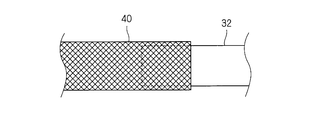
まず、図4に示すように、金属パイプ32及び筒状導電部材40を準備する。
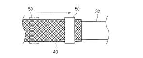
そして、図5に示すように、金属パイプ32の端部を筒状導電部材40内に挿入する。筒状導電部材40の端部を金属パイプ32の端部の外周に被せるということもできる。これにより、金属パイプ32の外周面側に筒状導電部材40の端部が配設される(工程(a))。
次に、図6に示すように、リング部材50を、筒状導電部材40のうち金属パイプ32に被せられた部分の外周にリング部材50を配設する。これにより、筒状導電部材40を金属パイプ32の外周面に押付けることができる(工程(b))。この工程は、例えば、筒状導電部材40のうち金属パイプ32とは反対の端部側からリング部材50を外嵌めし、当該リング部材50を筒状導電部材40に沿って金属パイプ32の端部の外周に向けて移動させて行うとよい。これにより、金属パイプ32とリング部材50との間に、筒状導電部材40の端部を挟込んだ状態とすることができる。この例では、リング部材50を1つだけ用いている。
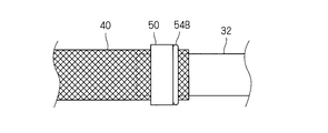
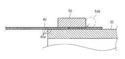
そして、図7に示すように、金属パイプ32の外周面側であって筒状導電部材40の端部が配設される箇所に、溶加材54Bを配設する(工程(c))。溶加材54Bは、はんだ、ろう材等であり、金属パイプ32及び筒状導電部材40に対して濡れ性が良好でかつそれらよりも融点の低い金属が用いられる。好ましくは、溶加材54Bは、リング部材50に対しても良好な濡れ性を示すものであり、ここでは、その前提で説明する。溶加材54Bは、例えば、糸状形態で提供され、金属パイプ32の周囲の筒状導電部材40の外周に巻付けることで、上記箇所に配設される。溶加材54Bの巻付回数は、1回又は複数回であることが好ましい。溶加材54Bは、リング部材50の端面に接する位置又は近接する位置に配設されることが好ましい。溶加材は、その他、板状、粒状の形態で提供されることもあり得る。
上記工程(a)、(b)、(c)の順は任意である。例えば、溶加材54Bを、金属パイプ32の周囲の筒状導電部材40の外周に巻付けた後、リング部材50を上記箇所に配設してもよい。また、溶加材54Bを金属パイプ32に巻付けた後、筒状導電部材40を金属パイプ32の外周側に配設する作業、及び、リング部材50を上記箇所に配設してもよい。また、リング部材50に対して溶加材54Bを予め取付けて一体化しておき、リング部材50と溶加材54Bとを同時に金属パイプ32の周囲の筒状導電部材40の外周に取付ける等してもよい。この場合、リング部材の内周に溝を形成しておき、当該溝に溶加材をセットしておくことと等で、リング部材と溶加材とを一体化できる。
また、溶加材54Bの配設位置は上記例に限られない。例えば、溶加材は、リング部材の内周側に配設されていてもよい。溶加材がリング部材の内周側に配設される場合、リング部材が筒状導電部材を金属パイプの外周面に向けて押付ける箇所とは別の箇所に溶加材が配設されていることが好ましい。
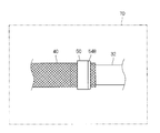
この後、図8及び図9に示すように、溶加材54Bを加熱して溶かして、溶けた溶加材54Bが金属パイプ32とリング部材50とに接して筒状導電部材40を金属パイプ32に接合する状態にする。加熱は、上記金属パイプ32、筒状導電部材40、金属パイプ32及び溶加材54Bを加熱炉70中に配設すること、又は、高周波誘導加熱、バーナーによる加熱等によって行うことができる。溶けた溶加材54Bは、金属パイプ32、リング部材50及び筒状導電部材40に対する良好な濡れ性を持っているため、リング部材50の端面と金属パイプ32の外周面のうち当該端面に向い合う部分との間に、金属線40a間を通って広がり、その部分で固化すると、筒状導電部材40を金属パイプ32の表面に接合する第1接合部54aとなる。また、溶けた溶加材54Bは、金属パイプ32、リング部材50及び筒状導電部材40に対して良好な濡れ性を持っているため、リング部材50の内周面と金属パイプ32の外周面との隙間に毛細管現状等によって入り込み、金属線40a間を通って広がる。そして、溶けた溶加材54Bがリング部材50の内周面と金属パイプ32の外周面との間で固化すると、筒状導電部材40を金属パイプ32の表面に接合する第2接合部54bとなる。
いずれにせよ、筒状導電部材40が金属パイプ32に押付けられた状態で、溶加材54Bが溶けてその後固化して接合部54となるため、筒状導電部材40が金属パイプ32に押付けられた状態を固定化して両者を接合できる。また、溶けた溶加材54Bは、リング部材50が筒状導電部材40を押付ける箇所の周囲で、リング部材50の表面に沿って溜って固化して接合部54となるため、この点からも、筒状導電部材40を金属パイプ32により確実に接合できる。
<効果等>
以上のように構成された電磁シールド部材30及び電磁シールド部材30の製造方法によると、筒状導電部材40の端部を金属パイプ32の外周面に配設し、リング部材50によって筒状導電部材40の端部を金属パイプ32の外周面に押付けているため、リング部材50によって筒状導電部材40を金属パイプ32の外周面に押付けた状態でろう接を行える。また、溶けた溶加材54Bは、筒状導電部材40を金属パイプ32に接合する状態となって接合部54を形成するため、溶けた溶加材54Bが周囲に広がり難くなる。このため、金属線40aが編まれて形成された筒状導電部材40を金属パイプ32に容易にろう接できる。
以上のように構成された電磁シールド部材30及び電磁シールド部材30の製造方法によると、筒状導電部材40の端部を金属パイプ32の外周面に配設し、リング部材50によって筒状導電部材40の端部を金属パイプ32の外周面に押付けているため、リング部材50によって筒状導電部材40を金属パイプ32の外周面に押付けた状態でろう接を行える。また、溶けた溶加材54Bは、筒状導電部材40を金属パイプ32に接合する状態となって接合部54を形成するため、溶けた溶加材54Bが周囲に広がり難くなる。このため、金属線40aが編まれて形成された筒状導電部材40を金属パイプ32に容易にろう接できる。
また、リング部材50は、金属パイプ32の周方向全体で、筒状導電部材40の端部を金属パイプ32の外周に押付けているため、接合部54は、金属パイプ32の周方向全体に亘って広がりやすくなり、リング部材50の周方向全体に延在する接合部54によって、筒状導電部材40を金属パイプ32の外周に接合することができる。
また、金属パイプ32及び筒状導電部材40のうち一方がアルミニウム又はアルミニウム合金により形成されていると、金属パイプ32及び筒状導電部材40のうちアルミニウム又はアルミニウム合金により形成されたものの表面の酸化皮膜を、ろう接する際に破壊又は除去して、筒状導電部材40を金属パイプ32に良好に接続できる。
特に、金属パイプ32及び筒状導電部材40の両方がアルミニウム又はアルミニウム合金により形成されていると、電磁シールド部材30の軽量化を図りつつ、筒状導電部材40を金属パイプ32に良好に接続できる。
また、シリコンを含むアルミニウム合金は、アルミニウムより融点が低く、アルミニウム又はアルミニウム合金をろう接するの適しており、かかる合金を溶加材として用いることで、筒状導電部材40を金属パイプ32に容易に接合できる。
また、溶加材54Bとしてアルミニウム又はアルミニウム合金に適したものを用いる場合、リング部材50としてもアルミニウム又はアルミニウム合金により形成されたものを用いると、接合部54はリング部材50も良好に接合される。このため、リング部材50も筒状導電部材40と筒状導電部材40との接続強度向上に貢献する。
また、接合部54は、金属パイプ32とリング部材50との間に介在して筒状導電部材40を金属パイプ32に接合するため、比較的少ない溶加材でも、筒状導電部材40を金属パイプ32に接合することができる。例えば、リング部材50が1つのみの場合であっても、リング部材50の内側の接合部によって筒状導電部材40を金属パイプ32に接合することができる。
{変形例}
上記実施形態では、接合部54がリング部材50の内周側及び一端面側に形成される例で説明したが、必ずしも上記構成である必要は無い。
上記実施形態では、接合部54がリング部材50の内周側及び一端面側に形成される例で説明したが、必ずしも上記構成である必要は無い。
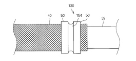
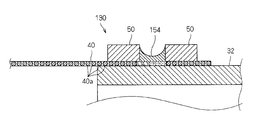
例えば、図10及び図11に示す電磁シールド部材130のように、複数のリング部材50が金属パイプ32の軸方向に沿って間隔をあけて設けられ、接合部154が、複数のリング部材50の間に介在して筒状導電部材40を金属パイプ32に接合する状態となっていてもよい。
この場合、例えば、図12及び図13に示すように、リング部材50を金属パイプ32の軸方向に沿って間隔をあけて複数箇所に設け、溶加材154Bを複数のリング部材50の間となる位置に配設し、この状態で、溶加材154Bを加熱して溶かし、溶けた溶加材154Bを複数のリング部材50の間でせき止めるように保ち、その部分で溶けた溶加材154Bを固化させて、筒状導電部材40を金属パイプ32に接合する接合部154を形成するとよい。
この例によっても、上記実施形態と同様の効果を得ることができる。
また、複数のリング部材50の間の接合部154によって、より確実に筒状導電部材40を金属パイプ32に接合することができる。なお、この場合においても、接合部154の一部が金属パイプ32とリング部材50との間に入り込んでもよい。
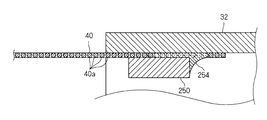
また、図14に示す変形例のように、筒状導電部材40の端部が金属パイプ32の内周面側に配設され、リング部材250がそれらの内周面側に嵌め込まれて筒状導電部材40の端部を金属パイプ32の内周面に向けて押付けた構成において、接合部254が金属パイプ32の内周面とリング部材250とに接して筒状導電部材40と金属パイプ32に接合する状態となっていてもよい。
この場合でも上記実施形態と同様の作用効果を得ることができる。
また、上記実施形態及び各変形例では、筒状導電部材40を金属パイプ32に押付ける押付部材がリング部材50、250である例で説明したが、必ずしもリング形状である必要は無い。例えば、押付部材は、金属パイプ周りの複数箇所で筒状導電部材を金属パイプに押付け可能な部材であり、接合部が金属パイプ周りで当該複数の押付け箇所の間に形成されていてもよい。
なお、上記実施形態及び各変形例で説明した各構成は、相互に矛盾しない限り適宜組合わせることができる。
例えば、図14に示す変形例において、図12及び図13に示す変形例と同様に、リング部材が間隔をあけて複数設けられ、それらの間に接合部が形成されていてもよい。
以上のようにこの発明は詳細に説明されたが、上記した説明は、すべての局面において、例示であって、この発明がそれに限定されるものではない。例示されていない無数の変形例が、この発明の範囲から外れることなく想定され得るものと解される。
10 配線モジュール
30、130 電磁シールド部材
32 金属パイプ
36 金属シェル
36b 筒部
40 筒状導電部材
40a 金属線
50、60、250 リング部材
54、64、154 接合部
54B、154B、254 溶加材
54a 第1接合部
54b 第2接合部
30、130 電磁シールド部材
32 金属パイプ
36 金属シェル
36b 筒部
40 筒状導電部材
40a 金属線
50、60、250 リング部材
54、64、154 接合部
54B、154B、254 溶加材
54a 第1接合部
54b 第2接合部
Claims (12)
- 筒部を有する金属製部材と、
金属線が編まれて筒形状に形成され、その端部が前記筒部の外周面側又は内周面側に配設された筒状導電部材と、
前記筒状導電部材を前記筒部の外周面又は内周面に押付ける押付部材と、
溶加材が溶けて固化することで前記筒状導電部材を前記筒部に接合する状態となった接合部と、
を備える電磁シールド部材。 - 請求項1に記載の電磁シールド部材であって、
前記押付部材は、前記筒部の周方向全体で、前記筒状導電部材を前記筒部の外周面又は内周面に押付けるリング部材であり、
前記接合部は、前記リング部材の周方向に沿って延在している、電磁シールド部材。 - 請求項1又は請求項2に記載の電磁シールド部材であって、
前記筒部及び前記筒状導電部材のうちの少なくとも一方は、アルミニウム又はアルミニウム合金により形成されている、電磁シールド部材。 - 請求項3に記載の電磁シールド部材であって、
前記筒部及び前記筒状導電部材のうちの両方が、アルミニウム又はアルミニウム合金により形成されている、電磁シールド部材。 - 請求項3又は請求項4に記載の電磁シールド部材であって、
前記接合部は、
シリコンを含むアルミニウム合金により形成された前記溶加材が溶けて固化することで前記筒状導電部材を前記筒部に接合する状態となったものである、電磁シールド部材。 - 請求項3から請求項5のいずれか1項に記載の電磁シールド部材であって、
前記押付部材がアルミニウム又はアルミニウム合金により形成されている、電磁シールド部材。 - 請求項1から請求項6のいずれか1項に記載の電磁シールド部材であって、
前記接合部は、前記筒部と前記押付部材との間に介在して前記筒状導電部材を前記筒部に接合する状態となっている、電磁シールド部材。 - 請求項1から請求項7のいずれか1項に記載の電磁シールド部材であって、
前記押付部材が前記筒部の軸方向に沿って間隔をあけて複数箇所に設けられ、
前記接合部は、複数箇所に設けられた前記押付部材の間に存在して前記筒状導電部材を前記筒部に接合する状態となっている、電磁シールド部材。 - 少なくとも1本の線状導体と、
前記線状導体を電磁シールドする請求項1から請求項8のいずれか1項に記載の電磁シールド部材と、
を備える配線モジュール。 - (a)筒部を有する金属製部材の前記筒部の外周面側又は内周面側に、金属線が編まれて筒形状に形成された筒状導電部材の端部を配設する工程と、
(b)前記筒部の外周面側又は内周面側に押付部材を配設し、前記筒状導電部材を前記筒部の外周面又は内周面に押付ける工程と、
(c)前記筒部の外周面側又は内周面側であって前記筒状導電部材の端部が配設される箇所に、溶加材を配設する工程と、
(d)前記工程(a)、(b)、(c)の後に、前記溶加材を溶かして、溶けた前記溶加材が固化することで前記筒状導電部材を前記筒部に接合する状態にする工程と、
を備える電磁シールド部材の製造方法。 - 請求項10に記載の電磁シールド部材の製造方法であって、
前記工程(d)において、溶けた前記溶加材が前記筒部と前記押付部材との間に流れ込んで、それらの間で固化することで前記筒状導電部材を前記筒部に接合する状態にする、電磁シールド部材の製造方法。 - 請求項10又は請求項11に記載の電磁シールド部材の製造方法であって、
前記工程(b)において、前記押付部材を前記筒部の軸方向に沿って間隔をあけて複数箇所に設け、
前記工程(c)において、前記溶加材を複数箇所に設けられる前記押付部材の間となる位置に配設し、
前記工程(d)において、溶けた前記溶加材が複数箇所に設けられた前記押付部材の間に保たれた状態で固化して、前記筒状導電部材を前記筒部に接合する、電磁シールド部材の製造方法。
Priority Applications (2)
| Application Number | Priority Date | Filing Date | Title |
|---|---|---|---|
| US16/303,404 US20190221328A1 (en) | 2016-05-20 | 2017-05-10 | Electromagnetic shielding member, wiring module, and method for manufacturing electromagnetic shielding member |
| CN201780030231.9A CN109156094B (zh) | 2016-05-20 | 2017-05-10 | 电磁屏蔽构件、布线模块以及电磁屏蔽构件的制造方法 |
Applications Claiming Priority (2)
| Application Number | Priority Date | Filing Date | Title |
|---|---|---|---|
| JP2016101292A JP6614026B2 (ja) | 2016-05-20 | 2016-05-20 | 電磁シールド部材、配線モジュール及び電磁シールド部材の製造方法 |
| JP2016-101292 | 2016-05-20 |
Publications (1)
| Publication Number | Publication Date |
|---|---|
| WO2017199814A1 true WO2017199814A1 (ja) | 2017-11-23 |
Family
ID=60325813
Family Applications (1)
| Application Number | Title | Priority Date | Filing Date |
|---|---|---|---|
| PCT/JP2017/017686 Ceased WO2017199814A1 (ja) | 2016-05-20 | 2017-05-10 | 電磁シールド部材、配線モジュール及び電磁シールド部材の製造方法 |
Country Status (4)
| Country | Link |
|---|---|
| US (1) | US20190221328A1 (ja) |
| JP (1) | JP6614026B2 (ja) |
| CN (1) | CN109156094B (ja) |
| WO (1) | WO2017199814A1 (ja) |
Families Citing this family (3)
| Publication number | Priority date | Publication date | Assignee | Title |
|---|---|---|---|---|
| JP7640313B2 (ja) * | 2021-03-19 | 2025-03-05 | 古河電気工業株式会社 | シールド外装および該シールド外装に備えられたワイヤーハーネス |
| JP7727491B2 (ja) * | 2021-11-09 | 2025-08-21 | 古河As株式会社 | 電磁シールド構造の製造方法 |
| CN114243390B (zh) * | 2021-12-14 | 2024-05-07 | 陕西航空电气有限责任公司 | 一种航空发动机点火电缆防波套组件连接结构 |
Citations (2)
| Publication number | Priority date | Publication date | Assignee | Title |
|---|---|---|---|---|
| JP2006164702A (ja) * | 2004-12-06 | 2006-06-22 | Hitachi Cable Ltd | シールド電線 |
| WO2015118937A1 (ja) * | 2014-02-06 | 2015-08-13 | 株式会社オートネットワーク技術研究所 | 電磁シールド部品および電磁シールド部品付電線 |
Family Cites Families (13)
| Publication number | Priority date | Publication date | Assignee | Title |
|---|---|---|---|---|
| FI55906C (fi) * | 1968-09-19 | 1979-10-10 | Aga Ab | Skarvdon foer foerbindning av pao utsidan slaeta roer |
| GB1424068A (en) * | 1973-04-10 | 1976-02-04 | Standard Telephones Cables Ltd | Jointing arrangement for a coaxial core |
| US4468080A (en) * | 1981-06-22 | 1984-08-28 | Automation Industries, Inc. | Cable shield termination means for plug and receptacle connectors |
| US4832248A (en) * | 1986-11-20 | 1989-05-23 | Raychem Corporation | Adhesive and solder connection device |
| US4858310A (en) * | 1988-04-12 | 1989-08-22 | W. L. Gore & Associates, Inc. | Method for soldering a metal ferrule to a flexible coaxial electrical cable |
| KR0173782B1 (ko) * | 1989-10-09 | 1999-02-01 | 나가노 다께시 | 전기 또는 전자회로의 성형에 사용되는 세라믹기판 |
| US6107572A (en) * | 1994-07-29 | 2000-08-22 | Sumitomo Wiring Systems, Ltd. | Terminal-processed structure of shielded cable and terminal-processing method of the same |
| JP2007080692A (ja) * | 2005-09-14 | 2007-03-29 | Auto Network Gijutsu Kenkyusho:Kk | シールド導電体 |
| JP2008006480A (ja) * | 2006-06-30 | 2008-01-17 | Sumitomo Light Metal Ind Ltd | 熱交換器用ブレージングフィン材並びに熱交換器及びその製造方法 |
| MX2011008140A (es) * | 2009-02-05 | 2011-08-17 | 3M Innovative Properties Co | Montaje de empalme con funda de proteccion. |
| JP5697232B2 (ja) * | 2010-09-02 | 2015-04-08 | 矢崎総業株式会社 | シールドコネクタ |
| JP2012182016A (ja) * | 2011-03-01 | 2012-09-20 | Auto Network Gijutsu Kenkyusho:Kk | シールド導電体 |
| JP6044475B2 (ja) * | 2013-07-04 | 2016-12-14 | 住友電装株式会社 | シールド導電体の製造方法 |
-
2016
- 2016-05-20 JP JP2016101292A patent/JP6614026B2/ja active Active
-
2017
- 2017-05-10 WO PCT/JP2017/017686 patent/WO2017199814A1/ja not_active Ceased
- 2017-05-10 CN CN201780030231.9A patent/CN109156094B/zh active Active
- 2017-05-10 US US16/303,404 patent/US20190221328A1/en not_active Abandoned
Patent Citations (2)
| Publication number | Priority date | Publication date | Assignee | Title |
|---|---|---|---|---|
| JP2006164702A (ja) * | 2004-12-06 | 2006-06-22 | Hitachi Cable Ltd | シールド電線 |
| WO2015118937A1 (ja) * | 2014-02-06 | 2015-08-13 | 株式会社オートネットワーク技術研究所 | 電磁シールド部品および電磁シールド部品付電線 |
Also Published As
| Publication number | Publication date |
|---|---|
| JP6614026B2 (ja) | 2019-12-04 |
| JP2017208499A (ja) | 2017-11-24 |
| US20190221328A1 (en) | 2019-07-18 |
| CN109156094B (zh) | 2020-03-31 |
| CN109156094A (zh) | 2019-01-04 |
Similar Documents
| Publication | Publication Date | Title |
|---|---|---|
| JP6278272B2 (ja) | 導電線及びその配索構造 | |
| JP6673404B2 (ja) | 導電部材 | |
| JP6251767B2 (ja) | 電磁干渉スプライスシールド | |
| JP6048859B2 (ja) | 導電線、導電線の製造方法及び導電線の配索構造 | |
| JP6582649B2 (ja) | シールド構造 | |
| CN102842774B (zh) | 电缆的连接结构和连接方法 | |
| WO2013175902A1 (ja) | 端子付き電線およびその製造方法、ならびに治具 | |
| JP4720168B2 (ja) | シールド電線 | |
| JP6376078B2 (ja) | 筒状導電性編組及び電磁シールド付配線モジュール | |
| JP6890222B2 (ja) | インダクター部品 | |
| JP6614026B2 (ja) | 電磁シールド部材、配線モジュール及び電磁シールド部材の製造方法 | |
| JP2017212313A (ja) | 電磁シールド部材、配線モジュール及び電磁シールド部材の製造方法 | |
| JP4691972B2 (ja) | シールド電線及びその製造方法 | |
| JP5527376B2 (ja) | シールド電線 | |
| JP2017073312A (ja) | 端子付電線及び熱収縮チューブ | |
| JP5640907B2 (ja) | ワイヤハーネス及びワイヤハーネスの製造方法 | |
| JP7727491B2 (ja) | 電磁シールド構造の製造方法 | |
| JP5168016B2 (ja) | シールド電線 | |
| JP2013196989A (ja) | 電線の接合構造 | |
| JP2024082856A (ja) | 電磁シールド構造、電磁シールド構造の製造方法 | |
| CN121646852A (zh) | 线束 | |
| JP2015076329A (ja) | 端子付電線 | |
| JP2017183154A (ja) | 熱収縮チューブ付電線の製造方法 | |
| JP2017126403A (ja) | シールド電線及びシールド電線の製造方法 | |
| JP2014067573A (ja) | 被覆電線と端子金具のシール構造および被覆電線と端子金具のシール方法 |
Legal Events
| Date | Code | Title | Description |
|---|---|---|---|
| NENP | Non-entry into the national phase |
Ref country code: DE |
|
| 121 | Ep: the epo has been informed by wipo that ep was designated in this application |
Ref document number: 17799239 Country of ref document: EP Kind code of ref document: A1 |
|
| 122 | Ep: pct application non-entry in european phase |
Ref document number: 17799239 Country of ref document: EP Kind code of ref document: A1 |