WO2017199812A1 - 投影部材、投影システム、投影部材の製造方法 - Google Patents
投影部材、投影システム、投影部材の製造方法 Download PDFInfo
- Publication number
- WO2017199812A1 WO2017199812A1 PCT/JP2017/017683 JP2017017683W WO2017199812A1 WO 2017199812 A1 WO2017199812 A1 WO 2017199812A1 JP 2017017683 W JP2017017683 W JP 2017017683W WO 2017199812 A1 WO2017199812 A1 WO 2017199812A1
- Authority
- WO
- WIPO (PCT)
- Prior art keywords
- liquid crystal
- projection
- light
- cholesteric liquid
- crystal phase
- Prior art date
- Legal status (The legal status is an assumption and is not a legal conclusion. Google has not performed a legal analysis and makes no representation as to the accuracy of the status listed.)
- Ceased
Links
Images





Classifications
-
- G—PHYSICS
- G03—PHOTOGRAPHY; CINEMATOGRAPHY; ANALOGOUS TECHNIQUES USING WAVES OTHER THAN OPTICAL WAVES; ELECTROGRAPHY; HOLOGRAPHY
- G03B—APPARATUS OR ARRANGEMENTS FOR TAKING PHOTOGRAPHS OR FOR PROJECTING OR VIEWING THEM; APPARATUS OR ARRANGEMENTS EMPLOYING ANALOGOUS TECHNIQUES USING WAVES OTHER THAN OPTICAL WAVES; ACCESSORIES THEREFOR
- G03B21/00—Projectors or projection-type viewers; Accessories therefor
- G03B21/54—Accessories
- G03B21/56—Projection screens
- G03B21/60—Projection screens characterised by the nature of the surface
- G03B21/604—Polarised screens
-
- G—PHYSICS
- G02—OPTICS
- G02B—OPTICAL ELEMENTS, SYSTEMS OR APPARATUS
- G02B5/00—Optical elements other than lenses
- G02B5/30—Polarising elements
- G02B5/3016—Polarising elements involving passive liquid crystal elements
Definitions
- the present invention relates to a projection member, a projection system, and a method for manufacturing the projection member.
- a layer formed by fixing a cholesteric liquid crystal phase is known as a layer having a property of selectively reflecting either right circularly polarized light or left circularly polarized light in a specific wavelength range. Therefore, it is developed for various uses, for example, application to a projection member is mentioned (patent document 1).
- the inventors of the present invention have made extensive studies on the above problem, and can solve the above problem by adjusting the helical pitch of the cholesteric liquid crystal phase in the plane direction of the reflective layer (along the surface of the reflective layer). I found out. That is, it has been found that the above problem can be solved by the following configuration.
- the helical pitch of the cholesteric liquid crystal phase increases as the distance from the projection light exit port of the projection device arranged away from the reflective layer surface increases.
- a projection system comprising: the projection member according to any one of (1) to (8); and a projection device that emits projection light to the projection member.
- a method for manufacturing a projection member according to any one of (1) to (8) A coating film is formed using a liquid crystal compound having a polymerizable group and a composition containing a chiral agent that is sensitive to light and can change the helical pitch of the cholesteric liquid crystal phase, and the coating film is heated to align the liquid crystal compound.
- the projection member by which the change of the color in the projection position was suppressed can be provided.
- the manufacturing method of a projection system and a projection member can also be provided.
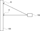
- FIG. 1 It is a schematic diagram at the time of emitting projection light from a projection device to a conventional projection member. It is a perspective view of one embodiment of the projection member of the present invention. It is a side view of one Embodiment of the projection system of this invention. It is a perspective view of other embodiment of the projection member of this invention. It is a side view of other embodiment of the projection system of this invention. It is a perspective view for demonstrating one Embodiment of the manufacturing method of the projection member of this invention. It is a perspective view for demonstrating other embodiment of the manufacturing method of the projection member of this invention. It is a perspective view for demonstrating other embodiment of the manufacturing method of the projection member of this invention. 5 is a perspective view for explaining an exposure method in Embodiment 1. FIG.
- a numerical range represented by using “to” means a range including numerical values described before and after “to” as a lower limit value and an upper limit value.
- an angle such as “parallel” means that a difference from a strict angle is within a range of less than 5 degrees unless otherwise specified. The difference from the exact angle is preferably less than 4 degrees, and more preferably less than 3 degrees.
- sense for circularly polarized light means right circularly polarized light or left circularly polarized light.
- the sense of circularly polarized light is right-handed circularly polarized light when the electric field vector tip turns clockwise as time increases when viewed as the light travels toward you, and left when it turns counterclockwise. Defined as being circularly polarized.
- the term “sense” may be used for the twist direction of the spiral of the cholesteric liquid crystal phase.
- the selective reflection by the cholesteric liquid crystal phase reflects right circularly polarized light and transmits left circularly polarized light when the twist direction (sense) of the spiral of the cholesteric liquid crystal phase is right, and reflects left circularly polarized light when the sense is left. Transmits right circularly polarized light.
- (meth) acrylate is a notation representing both acrylate and methacrylate
- (meth) acryloyl group is a notation representing both an acryloyl group and a methacryloyl group
- (Meth) acryl is a notation representing both acrylic and methacrylic.
- the projection member of the present invention has a reflective layer formed by fixing a cholesteric liquid crystal phase, and the helical pitch of the cholesteric liquid crystal phase gradually changes in the plane direction of the reflective layer (along the surface of the reflective layer).
- the conventional technique has a problem that the color changes depending on the position of the projection surface (projection position) of the projection member.
- the present inventors have found that the cause is that the wavelength of light reflected by the reflection layer formed by fixing the cholesteric liquid crystal phase varies depending on the incident angle of the projection light. Yes.
- the conventional projection member 100 shown in FIG. 1 includes a reflective layer formed by fixing a cholesteric liquid crystal phase having substantially the same helical pitch in all regions.
- projection light is incident substantially parallel to the normal direction of the surface of the projection member 100, so that light having a predetermined reflection center wavelength derived from the helical pitch of the cholesteric liquid crystal phase is reflected.
- point B of the projection member 100 projection light having a predetermined angle with respect to the normal direction of the surface of the projection member 100 is incident. Is done. This is because the wavelength of light reflected by the reflective layer formed by fixing the cholesteric liquid crystal phase shifts to the short wavelength side when the incident direction of light is inclined from the normal direction with respect to the layer surface. is there. As a result, there arises a problem that the color is different between the points A and B.
- the projection member of the present invention light having substantially the same wavelength is reflected at any position on the surface of the reflective layer by adjusting the helical pitch of the cholesteric liquid crystal phase in the plane direction of the reflective layer.
- the desired effect can be obtained. More specifically, for example, by increasing the helical pitch of the cholesteric liquid crystal phase as the distance from the projection light exit port of the projection device arranged away from the reflection layer surface becomes longer on the reflection layer surface, The above effects can be obtained.
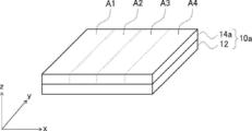
- FIG. 2 shows a perspective view of one embodiment of the projection member of the present invention.
- a projection member 10 a in FIG. 2 includes a substrate 12 and a reflective layer 14 a disposed on the substrate 12.
- the reflective layer 14a is a layer formed by fixing a cholesteric liquid crystal phase.
- the reflective layer 14a includes four regions (regions A1 to A4) with different cholesteric liquid crystal phase spiral pitch sizes (lengths), and the cholesteric liquid crystal phase spiral pitch of each region is in the x-axis direction. It becomes gradually larger (longer) along. That is, the relationship of the following formula (1) is satisfied.
- Formula (1) Spiral pitch of cholesteric liquid crystal phase in region A4> Spiral pitch of cholesteric liquid crystal phase in region A3> Spiral pitch of cholesteric liquid crystal phase in region A2> Spiral pitch of cholesteric liquid crystal phase in region A1
- the reflection center wavelength ⁇ of the reflection layer means a wavelength at the center of gravity position of the reflection peak of the circularly polarized reflection spectrum measured from the normal direction of the reflection layer.
- the reflection center wavelength ⁇ can be adjusted by adjusting the pitch length of the helical structure. Therefore, in the reflective layer 14a, each reflection center wavelength ⁇ from the region A1 to the region A4 satisfies the relationship of the following formula (2).
- Expression (2) reflection center wavelength ⁇ in region A4> reflection center wavelength ⁇ in region A3> reflection center wavelength ⁇ in region A2> reflection center wavelength ⁇ in region A1 That is, the reflection center wavelength ⁇ gradually increases from the region A1 to the region A4.
- FIG. 3 is a side view of a projection system 50a including the projection member 10a.
- the projection system 50a includes the projection member 10a and the projection device 16 that is disposed apart from the surface of the reflection layer 14a of the projection member 10a.
- the projection device 16 is arranged so as to be biased toward one end side of the projection member 10a.
- projection light is emitted from a projection light exit port (not shown) of the projection device 16 to the reflection layer 14a of the projection member 10a.
- the projection light emitted from the projection light exit of the projection device 16 is incident on the regions A1 to A4 at predetermined angles.
- FIG. 3 is a side view of a projection system 50a including the projection member 10a.
- the projection system 50a includes the projection member 10a and the projection device 16 that is disposed apart from the surface of the reflection layer 14a of the projection member 10a.
- the projection device 16 is arranged so as to be biased toward one end side of the projection member 10a.
- projection light is emitted from
- the incident angle of the projection light with respect to the normal direction of the surface of the reflective layer 14a as a reference (0 degree) increases from the region A1 to the region A4.
- the distance from the projection light exit of the projection apparatus becomes longer as the area A1 changes to the area A4.
- light reflected at a position where the incident angle of the projection light is large is shorter than the reflection center wavelength.
- the spiral pitch of the cholesteric liquid crystal phase is adjusted so as to increase from the region A1 to the region A4, and the reflection center wavelength increases in the first place from the region A1 to the region A4. Has been.
- the reflection center wavelength of the region A2 is larger than the reflection center wavelength of the region A1, but the incident angle of the projection light emitted from the projection device 16 is larger in the region A2 than in the region A1, and thus in the region A2.
- the wavelength of the reflected light is made shorter than the reflection center wavelength of the region A2.
- the wavelength of the light reflected by the region A2 and the wavelength of the light reflected by the region A1 are substantially the same.
- the same phenomenon as described above occurs with respect to the regions A3 and A4. Therefore, the wavelengths of light reflected from the region A1 to the region A4 of the reflective layer 14a are substantially the same.
- the color of the projected image becomes substantially the same at any position on the surface of the reflective layer 14a.
- FIG. 4 shows a perspective view of another embodiment of the projection member of the present invention.
- the projection member 10b in FIG. 4 includes a substrate 12 and a reflective layer 14b disposed on the substrate 12.
- the reflective layer 14b is a layer formed by fixing a cholesteric liquid crystal phase.
- the projection member 10b and the projection member 10a described above have different arrangements of regions having different helical pitches in the reflective layer.
- the reflective layer 14b includes four regions (regions A11 to A14) having different cholesteric liquid crystal phase spiral pitches, and extends from the center to the end of the reflective layer 14b. As a result, the helical pitch of the cholesteric liquid crystal phase gradually increases.
- Equation (3) Spiral pitch of cholesteric liquid crystal phase in region A14> Helical pitch of cholesteric liquid crystal phase in region A13> Helical pitch of cholesteric liquid crystal phase in region A12> Helical pitch of cholesteric liquid crystal phase in region A11
- each reflection center wavelength ⁇ from the region A11 to the region A14 satisfies the relationship of the following formula (4).
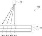
- FIG. 5 is a side view of a projection system 50b including the projection member 10b.
- the projection system 50b includes a projection member 10b and a projection device 16 that is disposed away from the surface of the reflection layer 14b of the projection member 10b.
- the projection device 16 is disposed at a position facing the projection member 10b.
- projection light is emitted from a projection light exit port (not shown) of the projection device 16 to the reflection layer 14b of the projection member 10b.
- the projection light emitted from the projection light exit of the projection device 16 is incident on the region A11 to the region A14 at a predetermined angle.
- FIG. 5 is a side view of a projection system 50b including the projection member 10b.
- the projection system 50b includes a projection member 10b and a projection device 16 that is disposed away from the surface of the reflection layer 14b of the projection member 10b.
- the projection device 16 is disposed at a position facing the projection member 10b.
- projection light is emitted from a projection
- the incident angle of the projection light with respect to the normal direction of the surface of the reflective layer 14b increases from the region A11 to the region A14.
- the distance from the projection light exit of the projection device 16 increases as the region A11 changes to the region A14.
- the spiral pitch of the cholesteric liquid crystal phase is adjusted so as to increase from the region A11 to the region A14, and from the region A11 to the region A14 in the first place. Accordingly, the reflection center wavelength is increased. Therefore, also in such a projection system 50b, the wavelength of light reflected from the region A11 to the region A14 of the reflective layer 14b is substantially the same as in the above-described form of FIG. Are substantially the same.
- FIG. 2 shows a form in which the spiral pitch of the cholesteric liquid crystal phase changes from one end to the other end of the reflective layer 14a
- FIG. 4 shows a spiral of the cholesteric liquid crystal phase from the center to the end of the reflective layer 14b.
- the present invention is not limited to these forms. In the present invention, it is only necessary to include a region in which the helical pitch of the cholesteric liquid crystal phase gradually changes in the plane direction of the reflective layer (along the surface of the reflective layer). That is, in the plane direction of the reflective layer, as long as at least part of the region where the spiral pitch of the cholesteric liquid crystal phase gradually changes is included, a region where the spiral pitch does not gradually change may be included.
- the spiral pitch of the cholesteric liquid crystal phase gradually changes from one end of the reflective layer toward the center, and the spiral pitch of the cholesteric liquid crystal phase does not change from the center to the other end.
- 2 and 4 show forms in which the helical pitch of the cholesteric liquid crystal phase changes stepwise, but the present invention is not limited to these forms.
- the spiral pitch may be changed continuously. More specifically, even if the spiral pitch of the cholesteric liquid crystal phase continuously changes from one end to the other end of the reflective layer 14a, the cholesteric liquid crystal phase from the center portion to the end portion of the reflective layer 14b.
- the spiral pitch may continuously change.
- the reflective layer having four regions has been described, but the present invention is not limited to this form.
- the reflection layer may include two or three regions having different cholesteric liquid crystal phase spiral pitches, and five or more regions having different cholesteric liquid crystal phase spiral pitches.
- the substrate is a plate that supports the reflective layer. Note that the substrate may not be included in the projection member, and is a so-called arbitrary constituent member.
- the substrate is preferably a transparent substrate.
- the transparent substrate intends a substrate having a visible light transmittance of 60% or more, and the transmittance is preferably 80% or more, and more preferably 90% or more.
- the material constituting the substrate is not particularly limited.
- cellulose polymer for example, cellulose polymer, polycarbonate polymer, polyester polymer, (meth) acrylic polymer, styrene polymer, polyolefin polymer, vinyl chloride polymer, amide polymer, imide
- examples thereof include a polymer, a sulfone polymer, a polyether sulfone polymer, and a polyether ether ketone polymer.
- the substrate may contain various additives such as UV (ultraviolet) absorbers, matting agent fine particles, plasticizers, deterioration inhibitors, and release agents.
- the substrate is preferably low birefringence in the visible light region.
- the retardation (in-plane retardation) at a wavelength of 550 nm of the substrate is preferably 50 nm or less, and more preferably 20 nm or less.
- the substrate may have a curved surface.
- the substrate may have a concave shape or a convex shape.
- the thickness of the substrate is not particularly limited, but is preferably 10 to 200 ⁇ m, more preferably 20 to 100 ⁇ m, from the viewpoints of thinning and handling properties.
- the above thickness is intended to mean an average thickness, and is obtained by measuring the thicknesses of five arbitrary points of the substrate and arithmetically averaging them.
- the reflective layer is a layer formed by fixing a cholesteric liquid crystal phase.
- the cholesteric liquid crystal phase has a circularly polarized light selective reflection property that selectively reflects either right circularly polarized light or left circularly polarized light.
- the layer formed by fixing the cholesteric liquid crystal phase is a layer in which the orientation of the liquid crystal compound in the cholesteric liquid crystal phase is maintained.
- a layer formed by fixing a cholesteric liquid crystal phase may be referred to as a cholesteric liquid crystal layer.
- the cholesteric liquid crystal layer is preferably a layer that is cured by light irradiation or the like after the polymerizable liquid crystal compound (liquid crystal compound having a polymerizable group) is aligned in the cholesteric liquid crystal phase.
- the state in which the cholesteric liquid crystal phase is “fixed” is a state in which the orientation of the liquid crystal compound in the cholesteric liquid crystal phase is maintained. More specifically, the state in which the cholesteric liquid crystal phase is “fixed” is usually 0 ° C. to 50 ° C., and under more severe conditions, in the temperature range of ⁇ 30 ° C.
- the layer has no fluidity
- the fixed alignment form can be kept stable without causing a change in the alignment form due to an external field or an external force.
- the optical properties of the cholesteric liquid crystal phase are maintained in the layer, and the liquid crystal compound in the layer may no longer exhibit liquid crystallinity.
- the polymerizable liquid crystal compound may have a high molecular weight due to a curing reaction and may no longer have liquid crystallinity.
- liquid crystal compounds can be classified according to their shapes into rod-shaped types (rod-shaped liquid crystal compounds) and disc-shaped types (discotic liquid crystal compounds, disc-shaped liquid crystal compounds). Furthermore, the rod-shaped type and the disk-shaped type include a low molecular type and a high molecular type, respectively.
- Polymer generally refers to polymers having a degree of polymerization of 100 or more (Polymer Physics / Phase Transition Dynamics, Masao Doi, 2 pages, Iwanami Shoten, 1992). In the present invention, any liquid crystal compound can be used. Two or more liquid crystal compounds may be used in combination.
- the liquid crystal compound may have a polymerizable group.
- the kind of the polymerizable group is not particularly limited, and a functional group capable of addition polymerization reaction is preferable, and a polymerizable ethylenically unsaturated group or a ring polymerizable group is preferable.
- the polymerizable group is preferably a (meth) acryloyl group, a vinyl group, a styryl group, an allyl group, an epoxy group, or an oxetane group, and more preferably a (meth) acryloyl group.
- the liquid crystal compound include polymerizable rod-shaped liquid crystal compounds. More specifically, Makromol.
- cholesteric liquid crystal layer whose spiral sense is either right or left may be used.
- the methods described in “Introduction to Liquid Crystal Chemistry Experiments”, edited by the Japanese Liquid Crystal Society, Sigma Publishing 2007, page 46, and “Liquid Crystal Handbook”, Liquid Crystal Handbook Editorial Committee, Maruzen, 196 pages are used. be able to.
- the layer formed by fixing the cholesteric liquid crystal phase exhibits circularly polarized light selective reflection derived from the helical structure of the cholesteric liquid crystal phase.
- the reflection center wavelength ⁇ can be adjusted within a range of 380 to 780 nm. Further, in order to selectively reflect either the right circularly polarized light or the left circularly polarized light in at least a part of the ultraviolet light wavelength region, the reflection center wavelength ⁇ can be adjusted within the range of 10 to 380 nm. Since the helical pitch of the cholesteric liquid crystal phase depends on the kind of chiral agent used together with the liquid crystal compound or the concentration of the chiral agent, the desired pitch can be obtained by adjusting these.
- the reflective layer may contain a compound other than the liquid crystal compound.
- the reflective layer may contain a chiral agent.
- the kind of chiral agent is not particularly limited.
- the chiral agent may be liquid crystalline or non-liquid crystalline.
- the chiral agent includes various known chiral agents (for example, Liquid Crystal Device Handbook, Chapter 3-4-3, TN (twisted nematic), STN (Super Twisted Nematic) chiral agent, page 199, Japan Society for the Promotion of Science, No. 142). From the Committee, 1989).
- Chiral agents generally contain asymmetric carbon atoms. However, an axially asymmetric compound or a planar asymmetric compound that does not contain an asymmetric carbon atom can also be used as a chiral agent.
- Examples of the axial asymmetric compound or the planar asymmetric compound include binaphthyl, helicene, paracyclophane, and derivatives thereof.
- the chiral agent may have a polymerizable group.
- a chiral agent may be used individually by 1 type, and may use 2 or more types together.
- a chiral agent that can change the helical pitch of the cholesteric liquid crystal phase in response to light hereinafter referred to as a chiral agent.
- a photosensitive chiral agent is a compound that changes its structure by absorbing light and can change the helical pitch of the cholesteric liquid crystal phase.
- a compound that causes at least one of a photoisomerization reaction, a photodimerization reaction, and a photolysis reaction is preferable.
- a compound that undergoes a photoisomerization reaction refers to a compound that undergoes stereoisomerization or structural isomerization by the action of light.
- a photoisomerization compound an azobenzene compound, a spiropyran compound, etc. are mentioned, for example.
- the compound that causes a photodimerization reaction refers to a compound that undergoes an addition reaction between two groups upon irradiation with light to cyclize.
- Examples of the photodimerization compound include cinnamic acid derivatives, coumarin derivatives, chalcone derivatives, and benzophenone derivatives.
- Preferred examples of the photosensitive chiral agent include chiral agents represented by the following general formula (I).
- This chiral agent can change the alignment structure such as the helical pitch (twisting force, helix twisting angle) of the cholesteric liquid crystal phase according to the amount of light upon light irradiation.
- Ar 1 and Ar 2 represent an aryl group or a heteroaromatic ring group.
- the aryl group represented by Ar 1 and Ar 2 may have a substituent, preferably has a total carbon number of 6 to 40, more preferably a total carbon number of 6 to 30.
- the substituent include a halogen atom, an alkyl group, an alkenyl group, an alkynyl group, an alkoxy group, a hydroxyl group, an acyl group, an alkoxycarbonyl group, an aryloxycarbonyl group, an acyloxy group, a carboxyl group, a cyano group, or a heterocyclic ring.
- Group is preferred, and a halogen atom, alkyl group, alkenyl group, alkoxy group, hydroxyl group, acyloxy group, alkoxycarbonyl group or aryloxycarbonyl group is more preferred.
- aryl groups represented by the following general formula (III) or (IV) are preferable.
- R 1 in the general formula (III) and R 2 in the general formula (IV) are each independently a hydrogen atom, a halogen atom, an alkyl group, an alkenyl group, an alkynyl group, an aryl group, a heterocyclic group, an alkoxy group, A hydroxyl group, an acyl group, an alkoxycarbonyl group, an aryloxycarbonyl group, an acyloxy group, a carboxyl group, or a cyano group is represented.
- a hydrogen atom, a halogen atom, an alkyl group, an alkenyl group, an aryl group, an alkoxy group, a hydroxyl group, an alkoxycarbonyl group, an aryloxycarbonyl group, or an acyloxy group is preferable, and an alkoxy group, a hydroxyl group, or an acyloxy group is preferred.
- L 1 in the general formula (III) and L 2 in the general formula (IV) each independently represent a halogen atom, an alkyl group, an alkoxy group, or a hydroxyl group, and an alkoxy group having 1 to 10 carbon atoms, Or a hydroxyl group is preferable.
- l represents 0 or an integer of 1 to 4, preferably 0 or 1.
- m represents 0 or an integer of 1 to 6, preferably 0 or 1.
- L 1 and L 2 may represent different groups.
- the heteroaromatic ring group represented by Ar 1 and Ar 2 may have a substituent, preferably has a total carbon number of 4 to 40, and more preferably a total carbon number of 4 to 30.
- a substituent for example, a halogen atom, an alkyl group, an alkenyl group, an alkynyl group, an aryl group, an alkoxy group, a hydroxyl group, an acyl group, an alkoxycarbonyl group, an aryloxycarbonyl group, an acyloxy group, or a cyano group is preferable.
- a halogen atom, an alkyl group, an alkenyl group, an aryl group, an alkoxy group, or an acyloxy group is more preferable.
- heteroaromatic ring group examples include a pyridyl group, a pyrimidinyl group, a furyl group, and a benzofuranyl group. Among them, a pyridyl group or a pyrimidinyl group is preferable.
- the reflective layer may have light diffusibility.
- the term “light diffusibility” intends the property that light incident on the reflection layer is reflected over a wide range. When the reflective layer has light diffusibility, images projected on the projection member surface from various directions can be visually recognized.
- a reflective layer including a light diffusing element can be mentioned.
- the light diffusing element include organic particles, inorganic particles, and bubbles. Examples of the material constituting the organic particles include styrene resins, acrylic resins, silicone resins, urea resins, and formaldehyde condensates. Examples of the material constituting the inorganic particles include glass beads, silica, alumina, calcium carbonate, and metal oxide.
- a reflective layer having an alignment defect of a liquid crystal compound can be mentioned.
- a reflective layer having light diffusivity a reflective layer having a structure (undulation structure) in which the angle formed by the helical axis of the cholesteric liquid crystal phase and the surface of the reflective layer changes periodically can be cited. .
- it is a layer in which a cholesteric liquid crystal phase is fixed, and in the cross-sectional view of the reflective layer observed with a scanning electron microscope, a stripe pattern of bright and dark portions derived from the cholesteric liquid crystal phase is given, and at least one
- This is a reflective layer in which the angle between the normal line of the dark part and the surface of the reflective layer changes periodically.
- the reflection layer having the alignment defect or the reflection layer having an undulation structure (wave structure) as described above is excellent in light diffusibility.
- the projection member may include a member other than the substrate and the reflective layer described above.
- an underlayer may be disposed between the substrate and the reflective layer.
- the material which comprises a base layer is not restrict
- the resin include known resins such as a (meth) acrylic resin, a styrene resin, and a polyolefin resin.
- the underlayer may contain an orientation control agent described later.
- a light diffusing layer may be disposed on the reflective layer.
- the light diffusion layer include a layer containing the above-described light diffusion element and binder, or a prism sheet having an uneven shape.
- the projection member may include various members such as a polarizing element, an antireflection film, a viewing angle compensation film, an adhesive layer, and an alignment film.
- the structure of the projection device is not particularly limited as long as it is a device that emits projection light to the above-described projection member.
- a so-called projector can be used as long as it can emit projection light having an arbitrary wavelength component.
- a three-tube CRT light source in which three primary color lights of R (red), G (green), and B (blue) are emitted from each CRT (Cathode Ray Tube) may be used.
- a single light source type projection device such as an LCD (Liquid Crystal Display) method in which the B primary color lights are emitted from individual pixels and a DLP (Digital Light Processing) method may be used.
- a light source of the projection device a laser light source, an LED (Light-Emitting Diode), a discharge tube, or the like can be used.
- the projection member including only one reflective layer has been described.
- the present invention is not limited to this configuration, and a plurality of reflective layers may be included.
- the projection member may include a reflective layer that reflects right circularly polarized light and a reflective layer that reflects left circularly polarized light.
- the projection member may include a plurality of reflection layers having different center reflection wavelengths.
- the projection member may include a reflective layer that reflects light in the blue wavelength region, a reflective layer that reflects light in the green wavelength region, and a reflective layer that reflects light in the red wavelength region. With such a projection member, full color can be realized.
- the blue wavelength region is preferably 430 nm or more and less than 500 nm
- the green wavelength region is preferably 500 nm or more and less than 600 nm
- the red wavelength region is specifically 600 nm.
- the thickness is preferably 650 nm or less.
- Step 1 Forming a coating film using a liquid crystal compound having a polymerizable group and a composition containing a chiral agent that is sensitive to light and can change the helical pitch of the cholesteric liquid crystal phase, and the coating film is heated to form a liquid crystal compound
- Step 2 in which the cholesteric liquid crystal phase is aligned by applying light to the coating film, and the spiral pitch of the cholesteric liquid crystal phase is changed in the surface direction of the coating film.
- Step 1 forms a coating film using a liquid crystal compound having a polymerizable group and a composition containing a chiral agent that is sensitive to light and can change the helical pitch of the cholesteric liquid crystal phase, and the coating film is heated to form a liquid crystal
- This is a step of orienting the compound to bring it into a cholesteric liquid crystal phase.
- the liquid crystal compound having a polymerizable group and the chiral agent capable of changing the helical pitch of the cholesteric liquid crystal phase in response to light are as described above.
- the composition may contain compounds other than the components described above.
- the composition may contain a polymerization initiator.
- the polymerization initiator is preferably a photopolymerization initiator capable of initiating a polymerization reaction by ultraviolet irradiation.
- Examples of the photopolymerization initiator include ⁇ -carbonyl compounds (described in US Pat. Nos. 2,367,661 and 2,367,670), acyloin ether (described in US Pat. No. 2,448,828), ⁇ -hydrocarbon substituted aromatic acyloin. Compound (described in US Pat. No. 2,722,512), polynuclear quinone compound (described in US Pat. Nos.
- the content of the polymerization initiator in the composition is not particularly limited, but is preferably 0.1 to 20% by mass with respect to the total mass of the liquid crystal compound.
- the composition may contain an alignment control agent.
- an alignment control agent By including an alignment control agent in the composition, it becomes possible to quickly form a cholesteric liquid crystal phase.
- the orientation control agent include fluorine-containing (meth) acrylate polymers, compounds represented by general formulas (X1) to (X3) described in WO2011 / 162291, and paragraphs of JP2013-47204A [ And the compounds described in [0031] to [0031]. You may contain 2 or more types selected from these. These compounds can reduce the tilt angle of the molecules of the liquid crystal compound or substantially horizontally align them at the air interface of the layer.
- “horizontal alignment” means that the major axis of the liquid crystal compound is parallel to the film surface, but it is not required to be strictly parallel.
- An orientation with an inclination angle of less than 20 degrees is meant.
- An orientation control agent may be used individually by 1 type, and may use 2 or more types together.
- the content of the alignment control agent in the composition is not particularly limited, but is preferably 0.01 to 10% by mass with respect to the total mass of the liquid crystal compound.
- the composition may contain a solvent.
- the solvent include water or an organic solvent.
- the organic solvent include amides such as N, N-dimethylformamide; sulfoxides such as dimethyl sulfoxide; heterocyclic compounds such as pyridine; hydrocarbons such as benzene and hexane; alkyl halides such as chloroform and dichloromethane; Esters such as methyl, butyl acetate, and propylene glycol monoethyl ether acetate; Ketones such as acetone, methyl ethyl ketone, cyclohexanone, and cyclopentanone; Ethers such as tetrahydrofuran and 1,2-dimethoxyethane; 1 , 4-butanediol diacetate; These may be used alone or in combination of two or more.
- Composition is one or more kinds of antioxidants, ultraviolet absorbers, sensitizers, stabilizers, plasticizers, chain transfer agents, polymerization inhibitors, antifoaming agents, leveling agents, thickeners Other additives such as flame retardants, surfactants, dispersants, and colorants such as dyes and pigments may be included.
- Examples of the method for forming a coating film in Step 1 include a method of applying the above-described composition onto a substrate.
- the application method is not particularly limited, and examples thereof include a wire bar coating method, an extrusion coating method, a direct gravure coating method, a reverse gravure coating method, and a die coating method.
- Examples of the substrate include a substrate that can be included in the above-described projection member.
- the thickness of the coating film is not particularly limited, but is preferably from 0.1 to 20 ⁇ m, more preferably from 0.2 to 15 ⁇ m, and even more preferably from 0.5 to 10 ⁇ m from the viewpoint that the reflectivity of the reflective layer is more excellent.
- the liquid crystal phase transition temperature of the composition is preferably from 10 to 250 ° C., more preferably from 10 to 150 ° C., from the viewpoint of production suitability.
- Step 2 is a step of irradiating the coating film in the cholesteric liquid crystal phase state to change the helical pitch of the cholesteric liquid crystal phase in the surface direction of the coating film.
- regions having different helical pitches can be formed in the coating film. More specifically, the structural change of the photosensitive chiral agent is induced by the light irradiation performed in this step, and the helical pitch of the cholesteric liquid crystal phase is changed.
- the coating film 20 is irradiated with light through the filter 18 as shown in FIG. A method is mentioned.
- the filter 18 has four regions T1 to T4, and the light transmittance increases in the order of the region T1 to the region T4. That is, in the region of the coating film 20 located below the region T1, the irradiation light is not so much irradiated and the helical pitch of the cholesteric liquid crystal phase does not change so much.
- the exposure amount irradiated to the coating film 20 via the filter 18 can be controlled, and as a result, the helical pitch of the cholesteric liquid crystal phase in the coating film 20 can be controlled.
- the structure of a filter is not restrict
- the reflective layer 14b shown in FIG. 4 can be manufactured by using a filter that increases the light transmittance from the center to the end.
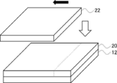
- the method of implementing light irradiation with respect to the coating film 20, shifting the mask 22, is mentioned.
- the mask 22 is arranged so that light is irradiated only in a partial region of the coating film 20 and the light irradiation is performed. Then, the mask 22 is moved in the direction of the black arrow and is shown in FIG. 8. Thus, light irradiation is implemented with respect to the coating film 20 again. In this case, the region R1 shown in FIG.
- the helical pitch of the cholesteric liquid crystal phase can be continuously changed in the surface direction of the coating film 20 by irradiating the coating film 20 with light while continuously moving the mask 22.
- the spiral pitch is increased when the light irradiation amount is increased.
- the spiral pitch is decreased when the light irradiation amount is increased.
- the wavelength of the light irradiated in this step is not particularly limited as long as it is a wavelength capable of inducing a structural change of the photosensitive chiral agent (wavelength at which the photosensitive chiral agent is exposed).
- a polymerization initiator when contained in the said composition, it is preferable to implement exposure with the light of the wavelength which a polymerization initiator is hard to expose.
- Step 3 is a step of forming a reflective layer formed by immobilizing the cholesteric liquid crystal phase by applying a curing treatment to the coating film that has been irradiated with light.
- the method for the curing treatment is not particularly limited, and examples thereof include photocuring treatment and thermosetting treatment. Of these, light irradiation treatment is preferable, and ultraviolet irradiation treatment is more preferable.
- a light source such as an ultraviolet lamp is used.
- the amount of ultraviolet irradiation energy is not particularly limited, but generally it is preferably about 0.1 to 0.8 J / cm 2 .
- the time for irradiation with ultraviolet rays is not particularly limited, but may be appropriately determined from the viewpoint of the strength and productivity of the obtained reflective layer.
- the projection member of the present invention can be used as, for example, a projection screen or a projection image display half mirror.
- the projection member of the present invention can display an image projected from the projector so as to be visible, and information or scenery on the opposite surface side when the projection member is observed from the same surface side where the image is displayed. Can be observed simultaneously.
- Air interface alignment agent (A-2) (structure below)
- Preparation of polymerizable composition coating solution 1 The following components were mixed to prepare a polymerizable composition coating liquid 1.
- Compound (M-1) 84 parts by mass Compound (M-2) 15 parts by mass Compound (M-3) 1 part by mass chiral agent LC-756 (manufactured by BASF) 3.6 parts by mass chiral agent (A-1) 1 .4 parts by mass Air interface alignment agent (A-2) 0.02 parts by mass Polymerization initiator Irg819 (manufactured by BASF) 3 parts by mass
- Polymerizable composition coating solution 2 The following components were mixed to prepare a polymerizable composition coating liquid 2.
- Compound (M-1) 100 parts by mass chiral agent LC-756 (manufactured by BASF) 4.8 parts by mass air interface alignment agent (A-2) 0.02 parts by mass polymerization initiator Irg819 (manufactured by BASF) 3 parts by mass 200 parts by mass of MEK
- Example 1 On a PET (polyethylene terephthalate) substrate (manufactured by Fuji Film, thickness 75 ⁇ m), the polymerizable composition coating liquid A was applied using a wire bar at room temperature so that the dry film thickness after drying was 5 ⁇ m. The obtained coating film was dried at room temperature for 30 seconds and then heated at 85 ° C. for 2 minutes. Thereafter, the coating film was irradiated with UV (ultraviolet rays) for 6 seconds at 30 ° C. with an output of a fusion D bulb (lamp 90 mW / cm 2 ) 60% to obtain an acrylic layer (corresponding to the underlayer).
- UV ultraviolet
- the polymerizable composition coating liquid 1 was applied onto the acrylic layer using a wire bar at room temperature such that the dry film thickness after drying was 4.0 ⁇ m.
- the obtained coating film was dried at room temperature for 30 seconds and then heated in an atmosphere at 85 ° C. for 1 minute to align the liquid crystal compound.
- exposure was performed at 30 ° C. using a 365 nm band pass filter so that the light corresponding to the edge corresponding to the edge when used as a screen was strongly irradiated (see FIG. 6). Specifically, as shown in FIG. 9, the exposure is performed so that the exposure amount at a position P1 30 cm away from the center C of the screen and a position P2 75 cm away from each other becomes the exposure amount shown in Table 1 described later.
- the reflective layer 1 Corresponding to a layer formed by fixing a cholesteric liquid crystal phase.
- the reflective layer 1 contained some orientation defects, and the reflective layer 1 itself had a scattering effect (light diffusion effect).
- the reflection center wavelength at a predetermined position of the reflective layer 1 was determined. The results are shown in Table 1 described later. As shown in Table 1, in the reflection layer 1, the longer the distance from the center, the longer the reflection center wavelength becomes.
- the reflectance was measured by combining absolute reflectance measuring unit ARV474S type. Further, the following reflection center wavelength means the wavelength at the center of the reflection peak when light is incident from a position inclined by 5 degrees with respect to the normal direction of the surface of the reflection layer.
- Example 1 On the acrylic layer produced by the same method as in Example 1, the polymerizable composition coating liquid 2 was applied at room temperature using a wire bar so that the dry film thickness after drying was 4.0 ⁇ m. . The obtained coating film was dried at room temperature for 10 seconds, and then heated at 85 ° C. for 1 minute. Subsequently, the coating layer was irradiated with UV at 40 ° C. for 5 seconds at an output of a fusion D bulb (lamp 90 mW / cm 2 ) 100% to obtain a reflective layer 2.
- a fusion D bulb lamp 90 mW / cm 2
- the reflection center wavelength at a predetermined position of the reflective layer 2 was determined using a spectrophotometer V-670 manufactured by JASCO. The results are shown in Table 2 described later.
- ⁇ Evaluation> Using the reflective layers 1 and 2 as a screen, a projector (WB-546T) manufactured by Seiko Epson was placed 72 cm away from the center of the screen, and a green image was projected to compare the color change.
- incident angle of projection light in Table 2 means an angle formed by a straight line connecting a position where the projector is installed and each position on the screen and a normal line on the screen surface.
- reflected wavelength at projection angle in Table 2 represents the wavelength of reflected light among the light incident on each position at the “incident angle of projection light”.
- the reflection layer 1 has substantially the same reflection wavelength at the center and the end (a position far from the center) of the screen, and there is almost no change in the color of the projection light.
- the reflective layer 2 as a comparative example, it was found that a noticeable color change from green to blue-green was observed at the edge of the screen, and the image itself was darkened.
- Example 2 instead of the mode using the 365 nm bandpass filter in Example 1, a filter that can obtain a reflective layer in which the spiral pitch of the cholesteric liquid crystal phase changes from the center to the end as shown in FIG. Then, exposure was performed to produce a reflective layer as shown in FIG. As shown in FIG. 5, when the projector is installed and a green image is projected on the obtained reflective layer, the reflection wavelength is reflected at the center and the end of the screen (positions far from the center). Were substantially the same, and there was almost no change in the color of the projected light.
Landscapes
- Physics & Mathematics (AREA)
- General Physics & Mathematics (AREA)
- Chemical & Material Sciences (AREA)
- Crystallography & Structural Chemistry (AREA)
- Optics & Photonics (AREA)
- Overhead Projectors And Projection Screens (AREA)
- Polarising Elements (AREA)
Abstract
本発明は、投影位置における色味の変化が抑制された投影部材、投影システム、および、投影部材の製造方法を提供する。本発明の投影部材(10a)は、コレステリック液晶相を固定してなる反射層(14a)を有し、反射層の面方向において、コレステリック液晶相の螺旋ピッチが徐々に変化する。
Description
本発明は、投影部材、投影システム、および、投影部材の製造方法に関する。
コレステリック液晶相を固定してなる層は、特定の波長域において右円偏光および左円偏光のいずれか一方を選択的に反射させる性質を有する層として知られている。そのため、種々の用途へ展開されており、例えば、投影部材への応用が挙げられる(特許文献1)。
一方で、投影部材のサイズが大きい場合、および、いわゆる台形補正機能を用いて投影を行う場合には、投影部材の投影面の位置によって色味の変化が生じる問題があった。
より具体的には、図1に示すように、従来のコレステリック液晶相を固定してなる反射層からなる投影部材100に対して、投影装置102より投影光を出射すると、投影部材100表面の中心部に位置するA地点における色味と、投影部材100表面の端部に位置するB地点における色味とが異なるという問題があった。
より具体的には、図1に示すように、従来のコレステリック液晶相を固定してなる反射層からなる投影部材100に対して、投影装置102より投影光を出射すると、投影部材100表面の中心部に位置するA地点における色味と、投影部材100表面の端部に位置するB地点における色味とが異なるという問題があった。
本発明は、上記実情を鑑みて、投影位置における色味の変化が抑制された投影部材を提供することを課題とする。
また、本発明は、投影システム、および、投影部材の製造方法を提供することも課題とする。
また、本発明は、投影システム、および、投影部材の製造方法を提供することも課題とする。
本発明者らは、上記課題に対して鋭意検討を行ったところ、反射層の面方向における(反射層の表面に沿った)コレステリック液晶相の螺旋ピッチを調整することにより、上記課題を解決できることを知見した。
すなわち、下記構成により、上記課題が解決できることを見出した。
すなわち、下記構成により、上記課題が解決できることを見出した。
(1) コレステリック液晶相を固定してなる反射層を有し、
反射層の面方向において、コレステリック液晶相の螺旋ピッチが徐々に変化する、投影部材。
(2) 反射層の中心部から端部に向かって、コレステリック液晶相の螺旋ピッチが徐々に大きくなる、(1)に記載の投影部材。
(3) 反射層の一端から他端に向かって、コレステリック液晶相の螺旋ピッチが徐々に変化する、(1)に記載の投影部材。
(4) 反射層表面において、反射層表面から離間して配置される投影装置の投影光出射口からの距離が長くなるに従って、コレステリック液晶相の螺旋ピッチが大きくなる、(1)~(3)のいずれかに記載の投影部材。
(5) 反射層が、光拡散性を有する、(1)~(4)のいずれかに記載の投影部材。
(6) 反射層が、光拡散要素を含む、(5)に記載の投影部材。
(7) 反射層上に、さらに光拡散層を有する、(1)~(6)のいずれかに記載の投影部材。
(8) 反射中心波長が異なる複数の反射層を有する、(1)~(7)のいずれかに記載の投影部材。
(9) (1)~(8)のいずれかに記載の投影部材と、投影部材に投影光を出射する投影装置とを備える、投影システム。
(10) (1)~(8)のいずれかに記載の投影部材の製造方法であって、
重合性基を有する液晶化合物、および、光に感応しコレステリック液晶相の螺旋ピッチを変化させ得るキラル剤を含む組成物を用いて塗膜を形成し、塗膜を加熱して液晶化合物を配向させてコレステリック液晶相の状態とする工程と、
塗膜に光照射を施し、塗膜の面方向において、コレステリック液晶相の螺旋ピッチを変化させる工程と、
光照射が施された塗膜に対して硬化処理を施し、コレステリック液晶相を固定化してなる反射層を形成する工程と、を有する投影部材の製造方法。
反射層の面方向において、コレステリック液晶相の螺旋ピッチが徐々に変化する、投影部材。
(2) 反射層の中心部から端部に向かって、コレステリック液晶相の螺旋ピッチが徐々に大きくなる、(1)に記載の投影部材。
(3) 反射層の一端から他端に向かって、コレステリック液晶相の螺旋ピッチが徐々に変化する、(1)に記載の投影部材。
(4) 反射層表面において、反射層表面から離間して配置される投影装置の投影光出射口からの距離が長くなるに従って、コレステリック液晶相の螺旋ピッチが大きくなる、(1)~(3)のいずれかに記載の投影部材。
(5) 反射層が、光拡散性を有する、(1)~(4)のいずれかに記載の投影部材。
(6) 反射層が、光拡散要素を含む、(5)に記載の投影部材。
(7) 反射層上に、さらに光拡散層を有する、(1)~(6)のいずれかに記載の投影部材。
(8) 反射中心波長が異なる複数の反射層を有する、(1)~(7)のいずれかに記載の投影部材。
(9) (1)~(8)のいずれかに記載の投影部材と、投影部材に投影光を出射する投影装置とを備える、投影システム。
(10) (1)~(8)のいずれかに記載の投影部材の製造方法であって、
重合性基を有する液晶化合物、および、光に感応しコレステリック液晶相の螺旋ピッチを変化させ得るキラル剤を含む組成物を用いて塗膜を形成し、塗膜を加熱して液晶化合物を配向させてコレステリック液晶相の状態とする工程と、
塗膜に光照射を施し、塗膜の面方向において、コレステリック液晶相の螺旋ピッチを変化させる工程と、
光照射が施された塗膜に対して硬化処理を施し、コレステリック液晶相を固定化してなる反射層を形成する工程と、を有する投影部材の製造方法。
本発明によれば、投影位置における色味の変化が抑制された投影部材を提供することができる。
また、本発明によれば、投影システム、および、投影部材の製造方法を提供することもできる。
また、本発明によれば、投影システム、および、投影部材の製造方法を提供することもできる。
以下、本発明について詳細に説明する。なお、本明細書において「~」を用いて表される数値範囲は、「~」の前後に記載される数値を下限値および上限値として含む範囲を意味する。
本明細書において、例えば、「平行」などの角度は、特に記載がなければ、厳密な角度との差異が5度未満の範囲内であることを意味する。厳密な角度との差異は、4度未満であることが好ましく、3度未満であることがより好ましい。
本明細書において、例えば、「平行」などの角度は、特に記載がなければ、厳密な角度との差異が5度未満の範囲内であることを意味する。厳密な角度との差異は、4度未満であることが好ましく、3度未満であることがより好ましい。
なお、本明細書において、円偏光につき「センス」というときは、右円偏光であるか、または、左円偏光であるかを意味する。円偏光のセンスは、光が手前に向かって進んでくるように眺めた場合に電場ベクトルの先端が時間の増加に従って時計回りに回る場合が右円偏光であり、反時計回りに回る場合が左円偏光であるとして定義される。
本明細書においては、コレステリック液晶相の螺旋の捩れ方向について「センス」との用語を用いることもある。コレステリック液晶相による選択反射は、コレステリック液晶相の螺旋の捩れ方向(センス)が右の場合は右円偏光を反射して左円偏光を透過し、センスが左の場合は左円偏光を反射して右円偏光を透過する。
本明細書においては、コレステリック液晶相の螺旋の捩れ方向について「センス」との用語を用いることもある。コレステリック液晶相による選択反射は、コレステリック液晶相の螺旋の捩れ方向(センス)が右の場合は右円偏光を反射して左円偏光を透過し、センスが左の場合は左円偏光を反射して右円偏光を透過する。
また、本明細書において、「(メタ)アクリレート」とは、アクリレートおよびメタクリレートの両方を表す表記であり、「(メタ)アクリロイル基」とは、アクリロイル基およびメタクリロイル基の両方を表す表記であり、「(メタ)アクリル」とは、アクリルおよびメタクリルの両方を表す表記である。
本発明の投影部材は、コレステリック液晶相を固定してなる反射層を有し、反射層の面方向において(反射層の表面に沿って)、コレステリック液晶相の螺旋ピッチが徐々に変化する。
上述したように、従来技術においては、投影部材の投影面の位置(投影位置)によって色味が変化するという問題があった。本発明者らはこの原因について検討を行った結果、投影光の入射角度によって、コレステリック液晶相を固定してなる反射層によって反射される光の波長が異なることが原因であることを知見している。
より具体的には、図1に示す従来の投影部材100は、全領域において略同一の螺旋ピッチを有するコレステリック液晶相を固定してなる反射層からなる。投影部材100のA地点においては、投影部材100表面の法線方向に略平行に投影光が入射するため、コレステリック液晶相の螺旋ピッチに由来する所定の反射中心波長の光が反射される。それに対して、投影部材100のB地点においては、投影部材100表面の法線方向に対して所定の角度をなす投影光が入射するため、A地点における反射中心波長からずれた波長の光が反射される。これは、光の入射方向が層面に対して法線方向から傾斜すると、コレステリック液晶相を固定してなる反射層によって反射される光の波長が、短波長側にシフトする傾向に由来するものである。
結果として、A地点とB地点とで、色味が異なるという問題が生じる。
上述したように、従来技術においては、投影部材の投影面の位置(投影位置)によって色味が変化するという問題があった。本発明者らはこの原因について検討を行った結果、投影光の入射角度によって、コレステリック液晶相を固定してなる反射層によって反射される光の波長が異なることが原因であることを知見している。
より具体的には、図1に示す従来の投影部材100は、全領域において略同一の螺旋ピッチを有するコレステリック液晶相を固定してなる反射層からなる。投影部材100のA地点においては、投影部材100表面の法線方向に略平行に投影光が入射するため、コレステリック液晶相の螺旋ピッチに由来する所定の反射中心波長の光が反射される。それに対して、投影部材100のB地点においては、投影部材100表面の法線方向に対して所定の角度をなす投影光が入射するため、A地点における反射中心波長からずれた波長の光が反射される。これは、光の入射方向が層面に対して法線方向から傾斜すると、コレステリック液晶相を固定してなる反射層によって反射される光の波長が、短波長側にシフトする傾向に由来するものである。
結果として、A地点とB地点とで、色味が異なるという問題が生じる。
それに対して、本発明の投影部材においては、反射層の面方向においてコレステリック液晶相の螺旋ピッチを調整することにより、反射層表面のいずれの位置においても略同一の波長の光が反射されるため、所望の効果が得られる。より具体的には、例えば、反射層表面において、反射層表面から離間して配置される投影装置の投影光出射口からの距離が長くなるに従って、コレステリック液晶相の螺旋ピッチを大きくすることにより、上記効果が得られる。言い換えれば、反射層表面の法線方向に対して投影光の入射角が大きい位置におけるコレステリック液晶相の螺旋ピッチを大きくすることにより、その位置における反射中心波長を長波長化させ、反射層全域で反射される光の色味が同じとなるように調整している。
以下、図面を用いて、本発明の投影部材について詳述する。
以下、図面を用いて、本発明の投影部材について詳述する。
図2は、本発明の投影部材の一実施形態の斜視図を表す。
図2中の投影部材10aは、基板12と、基板12上に配置された反射層14aとを有する。反射層14aは、コレステリック液晶相を固定してなる層である。反射層14aには、コレステリック液晶相の螺旋ピッチの大きさ(長さ)が異なる4つの領域(領域A1~A4)が含まれており、各領域のコレステリック液晶相の螺旋ピッチはx軸方向に沿って徐々に大きく(長く)なる。つまり、以下の式(1)の関係を満たす。
式(1):領域A4でのコレステリック液晶相の螺旋ピッチ>領域A3でのコレステリック液晶相の螺旋ピッチ>領域A2でのコレステリック液晶相の螺旋ピッチ>領域A1でのコレステリック液晶相の螺旋ピッチ
図2中の投影部材10aは、基板12と、基板12上に配置された反射層14aとを有する。反射層14aは、コレステリック液晶相を固定してなる層である。反射層14aには、コレステリック液晶相の螺旋ピッチの大きさ(長さ)が異なる4つの領域(領域A1~A4)が含まれており、各領域のコレステリック液晶相の螺旋ピッチはx軸方向に沿って徐々に大きく(長く)なる。つまり、以下の式(1)の関係を満たす。
式(1):領域A4でのコレステリック液晶相の螺旋ピッチ>領域A3でのコレステリック液晶相の螺旋ピッチ>領域A2でのコレステリック液晶相の螺旋ピッチ>領域A1でのコレステリック液晶相の螺旋ピッチ
一般的に、反射層の反射中心波長λ(nm)は、コレステリック液晶相における螺旋構造のピッチ長P(=螺旋の周期)に依存し、反射層の平均屈折率nとλ=n×Pの関係に従う。なお、本明細書において、反射層の反射中心波長λは、反射層の法線方向から測定した円偏光反射スペクトルの反射ピークの重心位置にある波長を意味する。上記式から分かるように、螺旋構造のピッチ長を調節することによって、反射中心波長λを調整できる。
よって、反射層14aにおいては、領域A1から領域A4の各反射中心波長λは、以下の式(2)の関係を満たす。
式(2):領域A4における反射中心波長λ>領域A3における反射中心波長λ>領域A2における反射中心波長λ>領域A1における反射中心波長λ
つまり、領域A1から領域A4になるに従って、反射中心波長λが徐々に大きくなる。
よって、反射層14aにおいては、領域A1から領域A4の各反射中心波長λは、以下の式(2)の関係を満たす。
式(2):領域A4における反射中心波長λ>領域A3における反射中心波長λ>領域A2における反射中心波長λ>領域A1における反射中心波長λ
つまり、領域A1から領域A4になるに従って、反射中心波長λが徐々に大きくなる。
図3は、投影部材10aを含む投影システム50aの側面図である。
投影システム50aは、投影部材10aと、投影部材10aの反射層14a表面から離間して配置される投影装置16とを含む。投影装置16は、投影部材10aの一端側に偏って配置される。
図3に示すように、投影装置16の図示しない投影光出射口から、投影部材10aの反射層14aに投影光が出射される。その際、投影装置16の投影光出射口から出射された投影光は、領域A1から領域A4に対してそれぞれ所定の角度で入射する。図3に示すように、反射層14a表面の法線方向を基準(0度)とした投影光の入射角は、領域A1から領域A4になるに従って大きくなる。言い換えれば、領域A1から領域A4になるに従って、投影装置の投影光出射口からの距離が長くなる。
上述したように、投影光の入射角が大きい位置(言い換えれば、投影装置の投影光出射口からの距離が長い位置)において反射される光は、反射中心波長よりも短波長化する。
それに対して、投影部材10aにおいては、領域A1から領域A4になるに従ってコレステリック液晶相の螺旋ピッチが大きくなるように調整されており、そもそも領域A1から領域A4になるに従って反射中心波長が長波長化されている。そのため、例えば、領域A2の反射中心波長は領域A1の反射中心波長よりも大きいが、投影装置16から出射された投影光の入射角度が領域A1よりも領域A2の方が大きいため、領域A2で反射される光の波長は、領域A2の反射中心波長よりもより短波長化される。結果として、領域A2で反射された光の波長と領域A1で反射された光の波長とは略同じなる。領域A3および領域A4に関しても、上記と同様の現象が生じる。
そのため、反射層14aの領域A1から領域A4にて反射される光の波長は、それぞれ略同じとなる。結果として、反射層14a表面のいずれの位置においても、投影像の色味が略同じとなる。
投影システム50aは、投影部材10aと、投影部材10aの反射層14a表面から離間して配置される投影装置16とを含む。投影装置16は、投影部材10aの一端側に偏って配置される。
図3に示すように、投影装置16の図示しない投影光出射口から、投影部材10aの反射層14aに投影光が出射される。その際、投影装置16の投影光出射口から出射された投影光は、領域A1から領域A4に対してそれぞれ所定の角度で入射する。図3に示すように、反射層14a表面の法線方向を基準(0度)とした投影光の入射角は、領域A1から領域A4になるに従って大きくなる。言い換えれば、領域A1から領域A4になるに従って、投影装置の投影光出射口からの距離が長くなる。
上述したように、投影光の入射角が大きい位置(言い換えれば、投影装置の投影光出射口からの距離が長い位置)において反射される光は、反射中心波長よりも短波長化する。
それに対して、投影部材10aにおいては、領域A1から領域A4になるに従ってコレステリック液晶相の螺旋ピッチが大きくなるように調整されており、そもそも領域A1から領域A4になるに従って反射中心波長が長波長化されている。そのため、例えば、領域A2の反射中心波長は領域A1の反射中心波長よりも大きいが、投影装置16から出射された投影光の入射角度が領域A1よりも領域A2の方が大きいため、領域A2で反射される光の波長は、領域A2の反射中心波長よりもより短波長化される。結果として、領域A2で反射された光の波長と領域A1で反射された光の波長とは略同じなる。領域A3および領域A4に関しても、上記と同様の現象が生じる。
そのため、反射層14aの領域A1から領域A4にて反射される光の波長は、それぞれ略同じとなる。結果として、反射層14a表面のいずれの位置においても、投影像の色味が略同じとなる。
図4に、本発明の投影部材の他の実施形態の斜視図を表す。
図4中の投影部材10bは、基板12と、基板12上に配置された反射層14bとを有する。反射層14bは、コレステリック液晶相を固定してなる層である。
投影部材10bと上述した投影部材10aとでは、反射層中の螺旋ピッチが異なる領域の配置が異なる。図4に示すように、反射層14bにおいては、コレステリック液晶相の螺旋ピッチの大きさが異なる4つの領域(領域A11~A14)が含まれており、反射層14bの中心部から端部に向かって、コレステリック液晶相の螺旋ピッチが徐々に大きくなる。つまり、領域A11から領域A14の各領域のコレステリック液晶相の螺旋ピッチは、以下の式(3)の関係を満たす。
式(3):領域A14でのコレステリック液晶相の螺旋ピッチ>領域A13でのコレステリック液晶相の螺旋ピッチ>領域A12でのコレステリック液晶相の螺旋ピッチ>領域A11でのコレステリック液晶相の螺旋ピッチ
よって、反射層14bにおいて、領域A11から領域A14の各反射中心波長λは、以下の式(4)の関係を満たす。
式(4):領域A14における反射中心波長λ>領域A13における反射中心波長λ>領域A12における反射中心波長λ>領域A11における反射中心波長λ
つまり、領域A11から領域A14になるに従って、反射中心波長λが徐々に大きくなる。
図4中の投影部材10bは、基板12と、基板12上に配置された反射層14bとを有する。反射層14bは、コレステリック液晶相を固定してなる層である。
投影部材10bと上述した投影部材10aとでは、反射層中の螺旋ピッチが異なる領域の配置が異なる。図4に示すように、反射層14bにおいては、コレステリック液晶相の螺旋ピッチの大きさが異なる4つの領域(領域A11~A14)が含まれており、反射層14bの中心部から端部に向かって、コレステリック液晶相の螺旋ピッチが徐々に大きくなる。つまり、領域A11から領域A14の各領域のコレステリック液晶相の螺旋ピッチは、以下の式(3)の関係を満たす。
式(3):領域A14でのコレステリック液晶相の螺旋ピッチ>領域A13でのコレステリック液晶相の螺旋ピッチ>領域A12でのコレステリック液晶相の螺旋ピッチ>領域A11でのコレステリック液晶相の螺旋ピッチ
よって、反射層14bにおいて、領域A11から領域A14の各反射中心波長λは、以下の式(4)の関係を満たす。
式(4):領域A14における反射中心波長λ>領域A13における反射中心波長λ>領域A12における反射中心波長λ>領域A11における反射中心波長λ
つまり、領域A11から領域A14になるに従って、反射中心波長λが徐々に大きくなる。
図5は、投影部材10bを含む投影システム50bの側面図である。
投影システム50bは、投影部材10bと、投影部材10bの反射層14b表面から離間して配置される投影装置16とを含む。投影装置16は、投影部材10bと対向する位置に配置される。
図5に示すように、投影装置16の図示しない投影光出射口から、投影部材10bの反射層14bに投影光が出射される。その際、投影装置16の投影光出射口から出射された投影光は、領域A11から領域A14に対してそれぞれ所定の角度で入射する。図5に示すように、領域A11から領域A14になるに従って、反射層14b表面の法線方向を基準とした投影光の入射角は大きくなる。言い換えれば、領域A11から領域A14になるに従って、投影装置16の投影光出射口からの距離が長くなる。
それに対して、投影部材10bにおいても、上記投影部材10aと同様に、領域A11から領域A14になるに従ってコレステリック液晶相の螺旋ピッチが大きくなるように調整されており、そもそも領域A11から領域A14になるに従って反射中心波長が長波長化されている。よって、このような投影システム50bにおいても、上述した図3の形態と同様に、反射層14bの領域A11から領域A14にて反射される光の波長は、略同じとなり、どの位置においても色味が略同じとなる。
投影システム50bは、投影部材10bと、投影部材10bの反射層14b表面から離間して配置される投影装置16とを含む。投影装置16は、投影部材10bと対向する位置に配置される。
図5に示すように、投影装置16の図示しない投影光出射口から、投影部材10bの反射層14bに投影光が出射される。その際、投影装置16の投影光出射口から出射された投影光は、領域A11から領域A14に対してそれぞれ所定の角度で入射する。図5に示すように、領域A11から領域A14になるに従って、反射層14b表面の法線方向を基準とした投影光の入射角は大きくなる。言い換えれば、領域A11から領域A14になるに従って、投影装置16の投影光出射口からの距離が長くなる。
それに対して、投影部材10bにおいても、上記投影部材10aと同様に、領域A11から領域A14になるに従ってコレステリック液晶相の螺旋ピッチが大きくなるように調整されており、そもそも領域A11から領域A14になるに従って反射中心波長が長波長化されている。よって、このような投影システム50bにおいても、上述した図3の形態と同様に、反射層14bの領域A11から領域A14にて反射される光の波長は、略同じとなり、どの位置においても色味が略同じとなる。
なお、図2においては反射層14aの一端から他端に向かってコレステリック液晶相の螺旋ピッチが変化する形態を、図4においては反射層14bの中心部から端部に向かってコレステリック液晶相の螺旋ピッチが大きくなる形態をそれぞれ示すが、本発明は、これらの形態には制限されない。本発明においては、反射層の面方向において(反射層の表面に沿って)、コレステリック液晶相の螺旋ピッチが徐々に変化する領域が含まれていればよい。つまり、反射層の面方向において、コレステリック液晶相の螺旋ピッチが徐々に変化する領域が少なくとも一部に含まれていれば、螺旋ピッチが徐々に変化しない領域が含まれていてもよい。例えば、反射層の一端から中央部に向かってコレステリック液晶相の螺旋ピッチが徐々に変化し、中央部から他端に向かってはコレステリック液晶相の螺旋ピッチが変化しない態様が挙げられる。
また、図2および図4においては、コレステリック液晶相の螺旋ピッチが段階的に変化する形態を示すが、本発明は、これらの形態には制限されない。例えば、上記螺旋ピッチが連続的に変化する形態であってもよい。より具体的には、反射層14aの一端から他端に向かってコレステリック液晶相の螺旋ピッチが連続的に変化する形態であっても、反射層14bの中心部から端部に向かってコレステリック液晶相の螺旋ピッチが連続的に変化する形態であってもよい。
また、図2および図4においては、4つの領域を有する反射層について述べたが、この形態には制限されない。例えば、反射層中に、コレステリック液晶相の螺旋ピッチが異なる2または3つの領域が含まれる形態、および、コレステリック液晶相の螺旋ピッチが異なる5つ以上の領域が含まれる形態であってもよい。
また、図2および図4においては、コレステリック液晶相の螺旋ピッチが段階的に変化する形態を示すが、本発明は、これらの形態には制限されない。例えば、上記螺旋ピッチが連続的に変化する形態であってもよい。より具体的には、反射層14aの一端から他端に向かってコレステリック液晶相の螺旋ピッチが連続的に変化する形態であっても、反射層14bの中心部から端部に向かってコレステリック液晶相の螺旋ピッチが連続的に変化する形態であってもよい。
また、図2および図4においては、4つの領域を有する反射層について述べたが、この形態には制限されない。例えば、反射層中に、コレステリック液晶相の螺旋ピッチが異なる2または3つの領域が含まれる形態、および、コレステリック液晶相の螺旋ピッチが異なる5つ以上の領域が含まれる形態であってもよい。
以下、投影部材、および、投影システムを構成する各部材について詳述する。
<基板>
基板は、反射層を支持する板である。なお、基板は投影部材に含まれていなくてもよく、いわゆる任意の構成部材である。
基板としては、透明基板であることが好ましい。なお、透明基板とは、可視光の透過率が60%以上である基板を意図し、その透過率は80%以上が好ましく、90%以上がより好ましい。
基板を構成する材料は特に制限されず、例えば、セルロース系ポリマー、ポリカーボネート系ポリマー、ポリエステル系ポリマー、(メタ)アクリル系ポリマー、スチレン系ポリマー、ポリオレフィン系ポリマー、塩化ビニル系ポリマー、アミド系ポリマー、イミド系ポリマー、スルホン系ポリマー、ポリエーテルスルホン系ポリマー、および、ポリエーテルエーテルケトン系ポリマーなどが挙げられる。
基板には、UV(紫外線)吸収剤、マット剤微粒子、可塑剤、劣化防止剤、および、剥離剤などの各種添加剤が含まれていてもよい。
なお、基板は、可視光領域で低複屈折性であることが好ましい。例えば、基板の波長550nmにおける位相差(面内レタデーション)は50nm以下であることが好ましく、20nm以下であることがより好ましい。
基板は、曲面を有していてもよい。また、基板は、凹型または凸型の形状を有していてもよい。
基板は、反射層を支持する板である。なお、基板は投影部材に含まれていなくてもよく、いわゆる任意の構成部材である。
基板としては、透明基板であることが好ましい。なお、透明基板とは、可視光の透過率が60%以上である基板を意図し、その透過率は80%以上が好ましく、90%以上がより好ましい。
基板を構成する材料は特に制限されず、例えば、セルロース系ポリマー、ポリカーボネート系ポリマー、ポリエステル系ポリマー、(メタ)アクリル系ポリマー、スチレン系ポリマー、ポリオレフィン系ポリマー、塩化ビニル系ポリマー、アミド系ポリマー、イミド系ポリマー、スルホン系ポリマー、ポリエーテルスルホン系ポリマー、および、ポリエーテルエーテルケトン系ポリマーなどが挙げられる。
基板には、UV(紫外線)吸収剤、マット剤微粒子、可塑剤、劣化防止剤、および、剥離剤などの各種添加剤が含まれていてもよい。
なお、基板は、可視光領域で低複屈折性であることが好ましい。例えば、基板の波長550nmにおける位相差(面内レタデーション)は50nm以下であることが好ましく、20nm以下であることがより好ましい。
基板は、曲面を有していてもよい。また、基板は、凹型または凸型の形状を有していてもよい。
基板の厚みは特に制限されないが、薄型化、および、取り扱い性の点から、10~200μmが好ましく、20~100μmがより好ましい。
上記厚みは平均厚みを意図し、基板の任意の5点の厚みを測定し、それらを算術平均したものである。
上記厚みは平均厚みを意図し、基板の任意の5点の厚みを測定し、それらを算術平均したものである。
<反射層>
反射層は、コレステリック液晶相を固定してなる層である。
コレステリック液晶相は、右円偏光および左円偏光のいずれか一方を選択的に反射する円偏光選択反射性を有する。
コレステリック液晶相を固定してなる層は、コレステリック液晶相となっている液晶化合物の配向が保持されている層である。本明細書においてコレステリック液晶相を固定してなる層を、コレステリック液晶層ということがある。コレステリック液晶層は重合性液晶化合物(重合性基を有する液晶化合物)をコレステリック液晶相の配向状態としたうえで、光照射などによって硬化した層であることが好ましい。
なお、ここで、コレステリック液晶相を「固定した」状態は、コレステリック液晶相となっている液晶化合物の配向が保持された状態である。より具体的には、コレステリック液晶相を「固定した」状態は、通常0℃~50℃、より過酷な条件下では-30℃~70℃の温度範囲において、層に流動性が無く、また、外場もしくは外力によって配向形態に変化を生じさせることなく、固定化された配向形態を安定に保ち続けることができる状態であることが好ましい。
なお、コレステリック液晶層においては、コレステリック液晶相の光学的性質が層中において保持されていれば十分であり、層中の液晶化合物はもはや液晶性を示していなくてもよい。例えば、重合性液晶化合物は、硬化反応により高分子量化して、もはや液晶性を失っていてもよい。
反射層は、コレステリック液晶相を固定してなる層である。
コレステリック液晶相は、右円偏光および左円偏光のいずれか一方を選択的に反射する円偏光選択反射性を有する。
コレステリック液晶相を固定してなる層は、コレステリック液晶相となっている液晶化合物の配向が保持されている層である。本明細書においてコレステリック液晶相を固定してなる層を、コレステリック液晶層ということがある。コレステリック液晶層は重合性液晶化合物(重合性基を有する液晶化合物)をコレステリック液晶相の配向状態としたうえで、光照射などによって硬化した層であることが好ましい。
なお、ここで、コレステリック液晶相を「固定した」状態は、コレステリック液晶相となっている液晶化合物の配向が保持された状態である。より具体的には、コレステリック液晶相を「固定した」状態は、通常0℃~50℃、より過酷な条件下では-30℃~70℃の温度範囲において、層に流動性が無く、また、外場もしくは外力によって配向形態に変化を生じさせることなく、固定化された配向形態を安定に保ち続けることができる状態であることが好ましい。
なお、コレステリック液晶層においては、コレステリック液晶相の光学的性質が層中において保持されていれば十分であり、層中の液晶化合物はもはや液晶性を示していなくてもよい。例えば、重合性液晶化合物は、硬化反応により高分子量化して、もはや液晶性を失っていてもよい。
一般的に、液晶化合物はその形状から、棒状タイプ(棒状液晶化合物)と円盤状タイプ(ディスコティック液晶化合物、円盤状液晶化合物)とに分類できる。さらに、棒状タイプおよび円盤状タイプには、それぞれ低分子タイプと高分子タイプとがある。高分子とは一般に重合度が100以上のものを指す(高分子物理・相転移ダイナミクス,土井 正男 著,2頁,岩波書店,1992)。本発明では、いずれの液晶化合物を用いることもできる。また、2種以上の液晶化合物を併用してもよい。
液晶化合物は、重合性基を有していてもよい。重合性基の種類は特に制限されず、付加重合反応が可能な官能基が好ましく、重合性エチレン性不飽和基または環重合性基が好ましい。より具体的には、重合性基としては、(メタ)アクリロイル基、ビニル基、スチリル基、アリル基、エポキシ基、および、オキセタン基が好ましく、(メタ)アクリロイル基がより好ましい。
液晶化合物としては、重合性棒状液晶化合物が挙げられ、より具体的には、Makromol. Chem., 190巻、2255頁(1989年)、Advanced Materials 5巻、107頁(1993年)、米国特許4683327号、同5622648号、同5770107号、WO95/22586号、同95/24455号、同97/00600号、同98/23580号、同98/52905号、同2008/133290号、特開平1-272551号、同6-16616号、同7-110469号、同11-80081号、特願2001-64627号、同2010-74759号、同2010-141468号、特開2008-19240号、同2013-166879号、同2014-198814号、および同2014-198815号などに記載の化合物を用いることができる。
液晶化合物としては、重合性棒状液晶化合物が挙げられ、より具体的には、Makromol. Chem., 190巻、2255頁(1989年)、Advanced Materials 5巻、107頁(1993年)、米国特許4683327号、同5622648号、同5770107号、WO95/22586号、同95/24455号、同97/00600号、同98/23580号、同98/52905号、同2008/133290号、特開平1-272551号、同6-16616号、同7-110469号、同11-80081号、特願2001-64627号、同2010-74759号、同2010-141468号、特開2008-19240号、同2013-166879号、同2014-198814号、および同2014-198815号などに記載の化合物を用いることができる。
コレステリック液晶層の反射円偏光のセンスは螺旋のセンスに一致する。そのため、コレステリック液晶層としては、螺旋のセンスが右および左のいずれかであるコレステリック液晶層を用いればよい。
なお、螺旋のセンスおよびピッチの測定法については「液晶化学実験入門」日本液晶学会編 シグマ出版2007年出版、46頁、および「液晶便覧」液晶便覧編集委員会 丸善 196頁に記載の方法を用いることができる。
なお、螺旋のセンスおよびピッチの測定法については「液晶化学実験入門」日本液晶学会編 シグマ出版2007年出版、46頁、および「液晶便覧」液晶便覧編集委員会 丸善 196頁に記載の方法を用いることができる。
コレステリック液晶相を固定してなる層は、コレステリック液晶相の螺旋構造に由来した円偏光選択反射を示す。円偏光の反射中心波長λは、上述したようにλ=n×Pの関係に従う。そのため、この螺旋構造のピッチを調節することによって、円偏光選択反射を示す波長を調整できる。
すなわち、n値とP値とを調節して、例えば、近赤外光波長域の少なくとも一部において右円偏光および左円偏光のいずれか一方を選択的に反射するために、反射中心波長λを780~2500nmの範囲内に調整できる。
また、可視光波長域の少なくとも一部において右円偏光および左円偏光のいずれか一方を選択的に反射するために、反射中心波長λを380~780nmの範囲内に調整できる。
さらに、紫外光波長域の少なくとも一部において右円偏光および左円偏光のいずれか一方を選択的に反射するために、反射中心波長λを10~380nmの範囲内に調整できる。
コレステリック液晶相の螺旋ピッチは、液晶化合物とともに用いるキラル剤の種類、またはその添加濃度に依存するため、これらを調整することによって所望のピッチを得ることができる。
すなわち、n値とP値とを調節して、例えば、近赤外光波長域の少なくとも一部において右円偏光および左円偏光のいずれか一方を選択的に反射するために、反射中心波長λを780~2500nmの範囲内に調整できる。
また、可視光波長域の少なくとも一部において右円偏光および左円偏光のいずれか一方を選択的に反射するために、反射中心波長λを380~780nmの範囲内に調整できる。
さらに、紫外光波長域の少なくとも一部において右円偏光および左円偏光のいずれか一方を選択的に反射するために、反射中心波長λを10~380nmの範囲内に調整できる。
コレステリック液晶相の螺旋ピッチは、液晶化合物とともに用いるキラル剤の種類、またはその添加濃度に依存するため、これらを調整することによって所望のピッチを得ることができる。
反射層には、上記液晶化合物以外の化合物が含まれていてもよい。
例えば、反射層には、キラル剤が含まれていてもよい。キラル剤の種類は、特に制限されない。キラル剤は液晶性であっても、非液晶性であってもよい。キラル剤は、公知の種々のキラル剤(例えば、液晶デバイスハンドブック、第3章4-3項、TN(twisted nematic)、STN(Super Twisted Nematic)用カイラル剤、199頁、日本学術振興会第142委員会編、1989に記載)から選択することができる。キラル剤は、一般に不斉炭素原子を含む。ただし、不斉炭素原子を含まない軸性不斉化合物または面性不斉化合物を、キラル剤として用いることもできる。軸性不斉化合物または面性不斉化合物の例には、ビナフチル、ヘリセン、パラシクロファンおよびこれらの誘導体が含まれる。キラル剤は、重合性基を有していてもよい。
キラル剤は、1種単独で用いてもよく、2種以上を併用してもよい。
例えば、反射層には、キラル剤が含まれていてもよい。キラル剤の種類は、特に制限されない。キラル剤は液晶性であっても、非液晶性であってもよい。キラル剤は、公知の種々のキラル剤(例えば、液晶デバイスハンドブック、第3章4-3項、TN(twisted nematic)、STN(Super Twisted Nematic)用カイラル剤、199頁、日本学術振興会第142委員会編、1989に記載)から選択することができる。キラル剤は、一般に不斉炭素原子を含む。ただし、不斉炭素原子を含まない軸性不斉化合物または面性不斉化合物を、キラル剤として用いることもできる。軸性不斉化合物または面性不斉化合物の例には、ビナフチル、ヘリセン、パラシクロファンおよびこれらの誘導体が含まれる。キラル剤は、重合性基を有していてもよい。
キラル剤は、1種単独で用いてもよく、2種以上を併用してもよい。
なお、後述するように、反射層を製造する際に、光照射によってコレステリック液晶相の螺旋ピッチの大きさを制御する場合、光に感応しコレステリック液晶相の螺旋ピッチを変化させ得るキラル剤(以後、感光性キラル剤とも称する)を用いることが好ましい。
感光性キラル剤とは、光を吸収することにより構造が変化し、コレステリック液晶相の螺旋ピッチを変化させ得る化合物である。このような化合物としては、光異性化反応、光二量化反応、および、光分解反応の少なくとも1つを起こす化合物が好ましい。
光異性化反応を起こす化合物とは、光の作用で立体異性化または構造異性化を起こす化合物をいう。光異性化化合物としては、例えば、アゾベンゼン化合物、および、スピロピラン化合物などが挙げられる。
また、光二量化反応を起こす化合物とは、光の照射によって、二つの基の間に付加反応を起こして環化する化合物をいう。光二量化化合物としては、例えば、桂皮酸誘導体、クマリン誘導体、カルコン誘導体、および、ベンゾフェノン誘導体などが挙げられる。
感光性キラル剤とは、光を吸収することにより構造が変化し、コレステリック液晶相の螺旋ピッチを変化させ得る化合物である。このような化合物としては、光異性化反応、光二量化反応、および、光分解反応の少なくとも1つを起こす化合物が好ましい。
光異性化反応を起こす化合物とは、光の作用で立体異性化または構造異性化を起こす化合物をいう。光異性化化合物としては、例えば、アゾベンゼン化合物、および、スピロピラン化合物などが挙げられる。
また、光二量化反応を起こす化合物とは、光の照射によって、二つの基の間に付加反応を起こして環化する化合物をいう。光二量化化合物としては、例えば、桂皮酸誘導体、クマリン誘導体、カルコン誘導体、および、ベンゾフェノン誘導体などが挙げられる。
上記感光性キラル剤としては、以下の一般式(I)で表されるキラル剤が好ましく挙げられる。このキラル剤は、光照射時の光量に応じてコレステリック液晶相の螺旋ピッチ(捻れ力、螺旋の捻れ角)などの配向構造を変化させ得る。

一般式(I)中、Ar1とAr2は、アリール基または複素芳香環基を表す。
Ar1とAr2で表されるアリール基は、置換基を有していてもよく、総炭素数6~40が好ましく、総炭素数6~30がより好ましい。置換基としては、例えば、ハロゲン原子、アルキル基、アルケニル基、アルキニル基、アルコキシ基、ヒドロキシル基、アシル基、アルコキシカルボニル基、アリールオキシカルボニル基、アシルオキシ基、カルボキシル基、シアノ基、または、複素環基が好ましく、ハロゲン原子、アルキル基、アルケニル基、アルコキシ基、ヒドロキシル基、アシルオキシ基、アルコキシカルボニル基、または、アリールオキシカルボニル基がより好ましい。
Ar1とAr2で表されるアリール基は、置換基を有していてもよく、総炭素数6~40が好ましく、総炭素数6~30がより好ましい。置換基としては、例えば、ハロゲン原子、アルキル基、アルケニル基、アルキニル基、アルコキシ基、ヒドロキシル基、アシル基、アルコキシカルボニル基、アリールオキシカルボニル基、アシルオキシ基、カルボキシル基、シアノ基、または、複素環基が好ましく、ハロゲン原子、アルキル基、アルケニル基、アルコキシ基、ヒドロキシル基、アシルオキシ基、アルコキシカルボニル基、または、アリールオキシカルボニル基がより好ましい。
このようなアリール基のうち、下記一般式(III)または(IV)式で表されるアリール基が好ましい。

一般式(III)中のR1および一般式(IV)中のR2は、それぞれ独立に、水素原子、ハロゲン原子、アルキル基、アルケニル基、アルキニル基、アリール基、複素環基、アルコキシ基、ヒドロキシル基、アシル基、アルコキシカルボニル基、アリールオキシカルボニル基、アシルオキシ基、カルボキシル基、または、シアノ基を表す。なかでも、水素原子、ハロゲン原子、アルキル基、アルケニル基、アリール基、アルコキシ基、ヒドロキシル基、アルコキシカルボニル基、アリールオキシカルボニル基、または、アシルオキシ基が好ましく、アルコキシ基、ヒドロキシル基、または、アシルオキシ基がより好ましい。
一般式(III)中のL1および一般式(IV)中のL2は、それぞれ独立に、ハロゲン原子、アルキル基、アルコキシ基、または、ヒドロキシル基を表し、炭素数1~10のアルコキシ基、または、ヒドロキシル基が好ましい。
lは0または1~4の整数を表し、0または1が好ましい。mは0または1~6の整数を表し、0または1が好ましい。lおよびmが2以上のときは、L1とL2は互いに異なる基を表してもよい。
一般式(III)中のL1および一般式(IV)中のL2は、それぞれ独立に、ハロゲン原子、アルキル基、アルコキシ基、または、ヒドロキシル基を表し、炭素数1~10のアルコキシ基、または、ヒドロキシル基が好ましい。
lは0または1~4の整数を表し、0または1が好ましい。mは0または1~6の整数を表し、0または1が好ましい。lおよびmが2以上のときは、L1とL2は互いに異なる基を表してもよい。
Ar1とAr2で表される複素芳香環基は、置換基を有していてもよく、総炭素数4~40が好ましく、総炭素数4~30がより好ましい。置換基としては、例えば、ハロゲン原子、アルキル基、アルケニル基、アルキニル基、アリール基、アルコキシ基、ヒドロキシル基、アシル基、アルコキシカルボニル基、アリールオキシカルボニル基、アシルオキシ基、または、シアノ基が好ましく、ハロゲン原子、アルキル基、アルケニル基、アリール基、アルコキシ基、または、アシルオキシ基がより好ましい。
複素芳香環基としては、ピリジル基、ピリミジニル基、フリル基、および、ベンゾフラニル基などが挙げられ、この中でも、ピリジル基、または、ピリミジニル基が好ましい。
複素芳香環基としては、ピリジル基、ピリミジニル基、フリル基、および、ベンゾフラニル基などが挙げられ、この中でも、ピリジル基、または、ピリミジニル基が好ましい。
反射層は、光拡散性を有していてもよい。光拡散性とは、反射層に入射した光が、広範囲に反射される性質を意図する。反射層が光拡散性を有する場合、種々の方向から投影部材表面に投影された像を視認できる。
光拡散性を有する反射層の一形態としては、光拡散要素を含む反射層が挙げられる。光拡散要素としては、有機系粒子、無機系粒子、および、気泡が挙げられる。有機系粒子を構成する材料としては、例えば、スチレン系樹脂、アクリル系樹脂、シリコーン系樹脂、尿素樹脂、および、ホルムアルデヒド縮合物などが挙げられる。無機系粒子を構成する材料としては、例えば、ガラスビーズ、シリカ、アルミナ、炭酸カルシウム、および、金属酸化物などが挙げられる。
光拡散性を有する反射層の一形態としては、光拡散要素を含む反射層が挙げられる。光拡散要素としては、有機系粒子、無機系粒子、および、気泡が挙げられる。有機系粒子を構成する材料としては、例えば、スチレン系樹脂、アクリル系樹脂、シリコーン系樹脂、尿素樹脂、および、ホルムアルデヒド縮合物などが挙げられる。無機系粒子を構成する材料としては、例えば、ガラスビーズ、シリカ、アルミナ、炭酸カルシウム、および、金属酸化物などが挙げられる。
光拡散性を有する反射層の他の形態としては、液晶化合物の配向欠陥を有する反射層が挙げられる。 また、光拡散性を有する反射層の他の形態としては、コレステリック液晶相の螺旋軸と反射層の表面とのなす角が周期的に変化する構造(アンジュレーション構造)を有する反射層が挙げられる。言い換えれば、コレステリック液晶相を固定化してなる層であって、走査型電子顕微鏡にて観測される反射層の断面図においてコレステリック液晶相由来の明部と暗部との縞模様を与え、少なくとも一つの暗部がなす線の法線と反射層の表面となす角が周期的に変化する、反射層である。
上記のような、配向欠陥を有する反射層、または、アンジュレーション構造(波状構造)を有する反射層であれば、光拡散性に優れる。
上記のような、配向欠陥を有する反射層、または、アンジュレーション構造(波状構造)を有する反射層であれば、光拡散性に優れる。
<その他の部材>
投影部材には、上述した基板および反射層以外の他の部材が含まれていてもよい。
例えば、基板と反射層との間には、下地層が配置されていてもよい。下地層を設けることにより、反射層中に液晶化合物の配向欠陥を効率よく形成できる。
下地層を構成する材料は特に制限されず、樹脂が好適に挙げられる。樹脂としては、例えば、(メタ)アクリル樹脂、スチレン樹脂、および、ポリオレフィン樹脂などの公知の樹脂が挙げられる。
なお、下地層には、後述する配向制御剤が含まれていてもよい。
投影部材には、上述した基板および反射層以外の他の部材が含まれていてもよい。
例えば、基板と反射層との間には、下地層が配置されていてもよい。下地層を設けることにより、反射層中に液晶化合物の配向欠陥を効率よく形成できる。
下地層を構成する材料は特に制限されず、樹脂が好適に挙げられる。樹脂としては、例えば、(メタ)アクリル樹脂、スチレン樹脂、および、ポリオレフィン樹脂などの公知の樹脂が挙げられる。
なお、下地層には、後述する配向制御剤が含まれていてもよい。
投影部材の光拡散性を向上させるために、反射層上には光拡散層が配置されていてもよい。光拡散層としては、上述した光拡散要素およびバインダーを含む層、または、凹凸形状を有するプリズムシートなどが挙げられる。
また、投影部材には、上記以外にも、偏光素子、反射防止膜、視野角補償膜、接着層、および、配向膜など種々の部材が含まれていてもよい。
<投影装置>
投影装置は、上述した投影部材に対して、投影光を出射する装置であれば、その構造は特に制限されない。投影装置としては、いわゆるプロジェクターが使用でき、任意の波長成分からなる投影光を出射できる装置であればよい。
例えば、R(赤)、G(緑)、B(青)の3原色光がそれぞれのCRT(Cathode Ray Tube)から出射される3管式のCRT光源であってもよいし、R、G、Bの3原色光が個々の画素から出射されるLCD(Liquid Crystal Display)方式、および、DLP(Digital Light Processing)方式などの単光源型の投影装置であってもよい。
投影装置の光源としては、レーザー光源、LED(Light‐Emitting Diode)、および、放電管などを用いることができる。
投影装置は、上述した投影部材に対して、投影光を出射する装置であれば、その構造は特に制限されない。投影装置としては、いわゆるプロジェクターが使用でき、任意の波長成分からなる投影光を出射できる装置であればよい。
例えば、R(赤)、G(緑)、B(青)の3原色光がそれぞれのCRT(Cathode Ray Tube)から出射される3管式のCRT光源であってもよいし、R、G、Bの3原色光が個々の画素から出射されるLCD(Liquid Crystal Display)方式、および、DLP(Digital Light Processing)方式などの単光源型の投影装置であってもよい。
投影装置の光源としては、レーザー光源、LED(Light‐Emitting Diode)、および、放電管などを用いることができる。
なお、上記図2~5においては、反射層が1層のみ含まれる投影部材について述べたがこの形態には制限されず、複数の反射層が含まれていてもよい。
例えば、右円偏光を反射する反射層と左円偏光を反射する反射層とが含まれる投影部材であってもよい。
また、投影部材には、中心反射波長が異なる複数の反射層が含まれていてもよい。例えば、青色波長域の光を反射する反射層と、緑色波長域の光を反射する反射層と、赤色波長域の光を反射する反射層とが含まれる投影部材であってもよい。このような投影部材であれば、フルカラー化が実現できる。
なお、青色波長域は具体的には、430nm以上500nm未満であることが好ましく、緑色波長域は具体的には、500nm以上600nm未満であることが好ましく、赤色波長域は具体的には、600nm以上650nm以下であることが好ましい。
例えば、右円偏光を反射する反射層と左円偏光を反射する反射層とが含まれる投影部材であってもよい。
また、投影部材には、中心反射波長が異なる複数の反射層が含まれていてもよい。例えば、青色波長域の光を反射する反射層と、緑色波長域の光を反射する反射層と、赤色波長域の光を反射する反射層とが含まれる投影部材であってもよい。このような投影部材であれば、フルカラー化が実現できる。
なお、青色波長域は具体的には、430nm以上500nm未満であることが好ましく、緑色波長域は具体的には、500nm以上600nm未満であることが好ましく、赤色波長域は具体的には、600nm以上650nm以下であることが好ましい。
<投影部材の製造方法>
上述した投影部材の製造方法は特に制限されず、公知の方法を採用できる。
なかでも、反射層中のコレステリック液晶相の螺旋ピッチの制御が容易である点から、以下の工程を有する製造方法が好ましい。
工程1:重合性基を有する液晶化合物、および、光に感応しコレステリック液晶相の螺旋ピッチを変化させ得るキラル剤を含む組成物を用いて塗膜を形成し、塗膜を加熱して液晶化合物を配向させてコレステリック液晶相の状態とする工程
工程2:塗膜に光照射を施し、塗膜の面方向において、コレステリック液晶相の螺旋ピッチを変化させる工程
工程3:光照射が施された塗膜に対して硬化処理を施し、コレステリック液晶相を固定化してなる反射層を形成する工程
以下、上記各工程の手順について詳述する。
上述した投影部材の製造方法は特に制限されず、公知の方法を採用できる。
なかでも、反射層中のコレステリック液晶相の螺旋ピッチの制御が容易である点から、以下の工程を有する製造方法が好ましい。
工程1:重合性基を有する液晶化合物、および、光に感応しコレステリック液晶相の螺旋ピッチを変化させ得るキラル剤を含む組成物を用いて塗膜を形成し、塗膜を加熱して液晶化合物を配向させてコレステリック液晶相の状態とする工程
工程2:塗膜に光照射を施し、塗膜の面方向において、コレステリック液晶相の螺旋ピッチを変化させる工程
工程3:光照射が施された塗膜に対して硬化処理を施し、コレステリック液晶相を固定化してなる反射層を形成する工程
以下、上記各工程の手順について詳述する。
(工程1)
工程1は、重合性基を有する液晶化合物、および、光に感応しコレステリック液晶相の螺旋ピッチを変化させ得るキラル剤を含む組成物を用いて塗膜を形成し、塗膜を加熱して液晶化合物を配向させてコレステリック液晶相の状態とする工程である。
重合性基を有する液晶化合物、および、光に感応しコレステリック液晶相の螺旋ピッチを変化させ得るキラル剤は上述の通りである。
工程1は、重合性基を有する液晶化合物、および、光に感応しコレステリック液晶相の螺旋ピッチを変化させ得るキラル剤を含む組成物を用いて塗膜を形成し、塗膜を加熱して液晶化合物を配向させてコレステリック液晶相の状態とする工程である。
重合性基を有する液晶化合物、および、光に感応しコレステリック液晶相の螺旋ピッチを変化させ得るキラル剤は上述の通りである。
組成物は、上述した成分以外の化合物を含んでいてもよい。
例えば、組成物は、重合開始剤を含んでいてもよい。
重合開始剤としては、紫外線照射によって重合反応を開始可能な光重合開始剤であることが好ましい。光重合開始剤としては、α-カルボニル化合物(米国特許第2367661号、同2367670号の各明細書記載)、アシロインエーテル(米国特許第2448828号明細書記載)、α-炭化水素置換芳香族アシロイン化合物(米国特許第2722512号明細書記載)、多核キノン化合物(米国特許第3046127号、同2951758号の各明細書記載)、トリアリールイミダゾールダイマーとp-アミノフェニルケトンとの組み合わせ(米国特許第3549367号明細書記載)、アクリジンおよびフェナジン化合物(特開昭60-105667号公報、米国特許第4239850号明細書記載)およびオキサジアゾール化合物(米国特許第4212970号明細書記載)などが挙げられる。
組成物中での重合開始剤の含有量は特に制限されないが、液晶化合物全質量に対して、0.1~20質量%が好ましい。
例えば、組成物は、重合開始剤を含んでいてもよい。
重合開始剤としては、紫外線照射によって重合反応を開始可能な光重合開始剤であることが好ましい。光重合開始剤としては、α-カルボニル化合物(米国特許第2367661号、同2367670号の各明細書記載)、アシロインエーテル(米国特許第2448828号明細書記載)、α-炭化水素置換芳香族アシロイン化合物(米国特許第2722512号明細書記載)、多核キノン化合物(米国特許第3046127号、同2951758号の各明細書記載)、トリアリールイミダゾールダイマーとp-アミノフェニルケトンとの組み合わせ(米国特許第3549367号明細書記載)、アクリジンおよびフェナジン化合物(特開昭60-105667号公報、米国特許第4239850号明細書記載)およびオキサジアゾール化合物(米国特許第4212970号明細書記載)などが挙げられる。
組成物中での重合開始剤の含有量は特に制限されないが、液晶化合物全質量に対して、0.1~20質量%が好ましい。
組成物は、配向制御剤を含んでいてもよい。組成物に配向制御剤が含まれることにより、迅速なコレステリック液晶相の形成が可能となる。
配向制御剤としては、例えば、含フッ素(メタ)アクリレート系ポリマー、WO2011/162291号に記載の一般式(X1)~(X3)で表される化合物、および特開2013-47204号公報の段落[0020]~[0031]に記載の化合物が挙げられる。これらから選択される2種以上を含有していてもよい。これらの化合物は、層の空気界面において、液晶化合物の分子のチルト角を低減または実質的に水平配向させることができる。なお、本明細書で「水平配向」とは、液晶化合物の長軸と膜面が平行であることをいうが、厳密に平行であることを要求するものではなく、本明細書では、水平面とのなす傾斜角が20度未満の配向を意味するものとする。
配向制御剤は、1種単独で用いてもよいし、2種以上を併用してもよい。
組成物中での配向制御剤の含有量は特に制限されないが、液晶化合物全質量に対して、0.01~10質量%が好ましい。
配向制御剤としては、例えば、含フッ素(メタ)アクリレート系ポリマー、WO2011/162291号に記載の一般式(X1)~(X3)で表される化合物、および特開2013-47204号公報の段落[0020]~[0031]に記載の化合物が挙げられる。これらから選択される2種以上を含有していてもよい。これらの化合物は、層の空気界面において、液晶化合物の分子のチルト角を低減または実質的に水平配向させることができる。なお、本明細書で「水平配向」とは、液晶化合物の長軸と膜面が平行であることをいうが、厳密に平行であることを要求するものではなく、本明細書では、水平面とのなす傾斜角が20度未満の配向を意味するものとする。
配向制御剤は、1種単独で用いてもよいし、2種以上を併用してもよい。
組成物中での配向制御剤の含有量は特に制限されないが、液晶化合物全質量に対して、0.01~10質量%が好ましい。
組成物は、溶媒を含んでいてもよい。
溶媒としては、水または有機溶媒が挙げられる。有機溶媒としては、例えば、N,N-ジメチルホルムアミドなどのアミド類;ジメチルスルホキシドなどのスルホキシド類;ピリジンなどのヘテロ環化合物;ベンゼンおよびヘキサンなどの炭化水素;クロロホルムおよびジクロロメタンなどのアルキルハライド類;酢酸メチル、酢酸ブチル、および、プロピレングリコールモノエチルエーテルアセテートなどのエステル類;アセトン、メチルエチルケトン、シクロヘキサノン、および、シクロペンタノンなどのケトン類;テトラヒドロフラン、および、1,2-ジメトキシエタンなどのエーテル類;1,4-ブタンジオールジアセテート;などが挙げられる。これらは1種単独で用いてもよく、2種以上を併用してもよい。
溶媒としては、水または有機溶媒が挙げられる。有機溶媒としては、例えば、N,N-ジメチルホルムアミドなどのアミド類;ジメチルスルホキシドなどのスルホキシド類;ピリジンなどのヘテロ環化合物;ベンゼンおよびヘキサンなどの炭化水素;クロロホルムおよびジクロロメタンなどのアルキルハライド類;酢酸メチル、酢酸ブチル、および、プロピレングリコールモノエチルエーテルアセテートなどのエステル類;アセトン、メチルエチルケトン、シクロヘキサノン、および、シクロペンタノンなどのケトン類;テトラヒドロフラン、および、1,2-ジメトキシエタンなどのエーテル類;1,4-ブタンジオールジアセテート;などが挙げられる。これらは1種単独で用いてもよく、2種以上を併用してもよい。
組成物は、1種または2種類以上の、酸化防止剤、紫外線吸収剤、増感剤、安定剤、可塑剤、連鎖移動剤、重合禁止剤、消泡剤、レべリング剤、増粘剤、難燃剤、界面活性剤、分散剤、ならびに、染料および顔料などの色材、などの他の添加剤を含んでいてもよい。
(工程1の手順)
工程1で塗膜を形成する方法としては、例えば、上述した組成物を基板上に塗布する方法が挙げられる。塗布方法は特に制限されず、例えば、ワイヤーバーコーティング法、押し出しコーティング法、ダイレクトグラビアコーティング法、リバースグラビアコーティング法、および、ダイコーティング法などが挙げられる。
なお、必要に応じて、塗布後に、基板上に塗布された組成物を乾燥する処理を実施してもよい。乾燥処理を実施することにより、塗布された組成物から溶媒を除去できる。
また、基板としては、上述した投影部材に含まれ得る基板が挙げられる。
工程1で塗膜を形成する方法としては、例えば、上述した組成物を基板上に塗布する方法が挙げられる。塗布方法は特に制限されず、例えば、ワイヤーバーコーティング法、押し出しコーティング法、ダイレクトグラビアコーティング法、リバースグラビアコーティング法、および、ダイコーティング法などが挙げられる。
なお、必要に応じて、塗布後に、基板上に塗布された組成物を乾燥する処理を実施してもよい。乾燥処理を実施することにより、塗布された組成物から溶媒を除去できる。
また、基板としては、上述した投影部材に含まれ得る基板が挙げられる。
塗膜の膜厚は特に制限されないが、反射層の反射性がより優れる点で、0.1~20μmが好ましく、0.2~15μmがより好ましく、0.5~10μmがさらに好ましい。
次に、塗膜を加熱して、塗膜中の液晶化合物を配向させてコレステリック液晶相の状態とする。
組成物の液晶相転移温度は、製造適性の点から、10~250℃が好ましく、10~150℃がより好ましい。
好ましい加熱条件としては、40~100℃(好ましくは、60~100℃)で0.5~5分間(好ましくは、0.5~2分間)にわたって組成物を加熱することが好ましい。
組成物の液晶相転移温度は、製造適性の点から、10~250℃が好ましく、10~150℃がより好ましい。
好ましい加熱条件としては、40~100℃(好ましくは、60~100℃)で0.5~5分間(好ましくは、0.5~2分間)にわたって組成物を加熱することが好ましい。
(工程2)
工程2は、コレステリック液晶相の状態の塗膜に光照射を施し、塗膜の面方向において、コレステリック液晶相の螺旋ピッチを変化させる工程である。本工程を実施することにより、塗膜中に螺旋ピッチの異なる領域を形成できる。より具体的には、本工程で行う光照射によって感光性キラル剤の構造変化が誘起され、コレステリック液晶相の螺旋ピッチが変化する。
工程2は、コレステリック液晶相の状態の塗膜に光照射を施し、塗膜の面方向において、コレステリック液晶相の螺旋ピッチを変化させる工程である。本工程を実施することにより、塗膜中に螺旋ピッチの異なる領域を形成できる。より具体的には、本工程で行う光照射によって感光性キラル剤の構造変化が誘起され、コレステリック液晶相の螺旋ピッチが変化する。
本工程の具体的な手順として、例えば、上述した図2に示す反射層14aを形成する形態としては、図6に示すように、フィルター18を介して塗膜20に対して光照射を実施する方法が挙げられる。フィルター18は、領域T1からT4の4つの領域を有し、領域T1から領域T4の順に光の透過率が高くなる。つまり、領域T1の下部に位置する塗膜20の領域においては、照射光はあまり照射されずコレステリック液晶相の螺旋ピッチはあまり変化しない。それに対して、領域T4の下部に位置する塗膜20の領域においては、照射光が多く照射されコレステリック液晶相の螺旋ピッチが大きくなる。つまり、フィルター18を介して、塗膜20に照射される露光量を制御でき、結果として塗膜20中のコレステリック液晶相の螺旋ピッチを制御できる。
なお、上記では図2に示す反射層14aを製造する場合について説明したが、フィルターの構成は上記形態に制限されない。例えば、中心部から端部に向かって光の透過率が高くなるフィルターを用いることにより、図4に示す反射層14bを製造することもできる。
なお、上記では図2に示す反射層14aを製造する場合について説明したが、フィルターの構成は上記形態に制限されない。例えば、中心部から端部に向かって光の透過率が高くなるフィルターを用いることにより、図4に示す反射層14bを製造することもできる。
また、工程2の他の方法としては、図7および図8に示すように、マスク22をずらしながら塗膜20に対して光照射を実施する方法が挙げられる。
図7に示すように、塗膜20の一部の領域のみ光が照射されるようにマスク22を配置して光照射を実施した後、マスク22を黒矢印方向に移動させ、図8に示すように、再度塗膜20に対して光照射を実施する。この場合、図8に示す、領域R1は2回の光照射が施されることになり、キラル剤の構造変化がより誘起され、結果として領域R2と比較して領域R1においてコレステリック液晶相の螺旋ピッチがより大きくなる。この作業を繰り返すことにより、上述した図2に示す反射層を得ることができる。
上記ではマスク22を段階的に移動させる形態について説明したが、この形態には制限されない。例えば、マスク22を連続的に移動させながら塗膜20に対して光照射を実施することにより、塗膜20の面方向において、コレステリック液晶相の螺旋ピッチを連続的に変化させることができる。
図7に示すように、塗膜20の一部の領域のみ光が照射されるようにマスク22を配置して光照射を実施した後、マスク22を黒矢印方向に移動させ、図8に示すように、再度塗膜20に対して光照射を実施する。この場合、図8に示す、領域R1は2回の光照射が施されることになり、キラル剤の構造変化がより誘起され、結果として領域R2と比較して領域R1においてコレステリック液晶相の螺旋ピッチがより大きくなる。この作業を繰り返すことにより、上述した図2に示す反射層を得ることができる。
上記ではマスク22を段階的に移動させる形態について説明したが、この形態には制限されない。例えば、マスク22を連続的に移動させながら塗膜20に対して光照射を実施することにより、塗膜20の面方向において、コレステリック液晶相の螺旋ピッチを連続的に変化させることができる。
また、上記では、光照射量が増加する場合に螺旋ピッチが大きくなる形態について述べたが、感光性キラル剤の種類を変えることにより、光照射量が増加する場合に螺旋ピッチが小さくなる形態とすることもできる。
本工程で照射される光の波長としては、感光性キラル剤の構造変化を誘起できる波長(感光性キラル剤が感光する波長)であれば特に制限されない。
なお、上記組成物に重合開始剤が含まれる場合、重合開始剤が感光しづらい波長の光で露光を実施することが好ましい。
なお、上記組成物に重合開始剤が含まれる場合、重合開始剤が感光しづらい波長の光で露光を実施することが好ましい。
(工程3)
工程3は、光照射が施された塗膜に対して硬化処理を施し、コレステリック液晶相を固定化してなる反射層を形成する工程である。
硬化処理の方法は特に制限されず、光硬化処理および熱硬化処理が挙げられる。なかでも、光照射処理が好ましく、紫外線照射処理がより好ましい。
紫外線照射には、紫外線ランプなどの光源が利用される。
紫外線の照射エネルギー量は特に制限されないが、一般的には、0.1~0.8J/cm2程度が好ましい。また、紫外線を照射する時間は特に制限されないが、得られる反射層の強度および生産性の観点から適宜決定すればよい。
工程3は、光照射が施された塗膜に対して硬化処理を施し、コレステリック液晶相を固定化してなる反射層を形成する工程である。
硬化処理の方法は特に制限されず、光硬化処理および熱硬化処理が挙げられる。なかでも、光照射処理が好ましく、紫外線照射処理がより好ましい。
紫外線照射には、紫外線ランプなどの光源が利用される。
紫外線の照射エネルギー量は特に制限されないが、一般的には、0.1~0.8J/cm2程度が好ましい。また、紫外線を照射する時間は特に制限されないが、得られる反射層の強度および生産性の観点から適宜決定すればよい。
<用途>
本発明の投影部材は、例えば、投影スクリーン、または、投映像表示用ハーフミラーなどとして用いることができる。
なお、本発明の投影部材は、プロジェクターから投映された画像を視認可能に表示できるとともに、画像が表示されている同じ面側から投影部材を観察したときに、反対の面側にある情報または風景を同時に観察できる。
本発明の投影部材は、例えば、投影スクリーン、または、投映像表示用ハーフミラーなどとして用いることができる。
なお、本発明の投影部材は、プロジェクターから投映された画像を視認可能に表示できるとともに、画像が表示されている同じ面側から投影部材を観察したときに、反対の面側にある情報または風景を同時に観察できる。
以下に実施例と比較例を挙げて本発明の特徴をさらに具体的に説明する。以下の実施例に示す材料、使用量、割合、処理内容、および、処理手順などは、本発明の趣旨を逸脱しない限り適宜変更できる。従って、本発明の範囲は以下に示す具体例により制限的に解釈されるべきものではない。
(重合性組成物塗布液Aの調製)
以下の成分を混合して、重合性組成物塗布液Aを調製した。
ブレンマー758 100質量部
空気界面配向剤(A-2) 0.02質量部
重合開始剤Irg819(BASF社製) 3質量部
MEK(メチルエチルケトン) 200質量部
以下の成分を混合して、重合性組成物塗布液Aを調製した。
ブレンマー758 100質量部
空気界面配向剤(A-2) 0.02質量部
重合開始剤Irg819(BASF社製) 3質量部
MEK(メチルエチルケトン) 200質量部
空気界面配向剤(A-2)(下記構造)

(重合性組成物塗布液1の調製)
以下の成分を混合して、重合性組成物塗布液1を調製した。
化合物(M-1) 84質量部
化合物(M-2) 15質量部
化合物(M-3) 1質量部
キラル剤LC-756(BASF社製) 3.6質量部
キラル剤(A-1) 1.4質量部
空気界面配向剤(A-2) 0.02質量部
重合開始剤Irg819(BASF社製) 3質量部
以下の成分を混合して、重合性組成物塗布液1を調製した。
化合物(M-1) 84質量部
化合物(M-2) 15質量部
化合物(M-3) 1質量部
キラル剤LC-756(BASF社製) 3.6質量部
キラル剤(A-1) 1.4質量部
空気界面配向剤(A-2) 0.02質量部
重合開始剤Irg819(BASF社製) 3質量部
化合物(M-1)(下記構造)

化合物(M-2)(下記構造)

化合物(M-3)(下記構造)

キラル剤(A-1)(下記構造)

(重合性組成物塗布液2)
以下の成分を混合して、重合性組成物塗布液2を調製した。
化合物(M-1) 100質量部
キラル剤LC-756(BASF社製) 4.8質量部
空気界面配向剤(A-2) 0.02質量部
重合開始剤Irg819(BASF社製) 3質量部
MEK 200質量部
以下の成分を混合して、重合性組成物塗布液2を調製した。
化合物(M-1) 100質量部
キラル剤LC-756(BASF社製) 4.8質量部
空気界面配向剤(A-2) 0.02質量部
重合開始剤Irg819(BASF社製) 3質量部
MEK 200質量部
<実施例1>
PET(polyethylene terephthalate)基板(富士フイルム製、厚み75μm)上に、重合性組成物塗布液Aを乾燥後の乾膜の厚みが5μmになるように室温にてワイヤーバーを用いて、塗布した。得られた塗膜を室温にて30秒間乾燥させた後、85℃の雰囲気で2分間加熱した。その後、塗膜に対して30℃にてフュージョン製Dバルブ(ランプ90mW/cm2)の出力60%で6秒間UV(紫外線)を照射し、アクリル層(下地層に該当)を得た。
続いて、このアクリル層の上に、乾燥後の乾膜の厚みが4.0μmになるように室温にてワイヤーバーを用いて、重合性組成物塗布液1を塗布した。得られた塗膜を室温にて30秒間乾燥させた後、85℃の雰囲気で1分間加熱して液晶化合物を配向させた。
次に、スクリーンとして用いる場合の端部に相当する部分ほど光が強く当たるように、365nmのバンドパスフィルターを用いて30℃にて露光した(図6参照)。具体的には、図9に示すように、スクリーンの中心Cからの30cm離れた位置P1および75cm離れた位置P2における露光量が、後述する表1に示す露光量となるように、露光を行った。なお、図9に示す、破線で区切られた3つの領域(R11、R12、R13)のそれぞれにおいて、同一領域内には同じ露光量となるように、バンドパスフィルターによる照射が行われた。より具体的には、中心Cを含む領域R11での露光量は0、位置P1を含む領域R12での露光量は5mW/cm2、位置P2を含む領域R13での露光量は15mW/cm2であった。
続いて、露光処理が施された塗膜に対して、フュージョン製Dバルブ(ランプ90mW/cm2)の出力100%で5秒間、フィルターを用いずに40℃にてUV照射し、反射層1(コレステリック液晶相を固定化してなる層に該当)を形成した。
なお、反射層1には配向欠陥が一部含まれており、反射層1自体が散乱効果(光拡散効果)を有していた。
PET(polyethylene terephthalate)基板(富士フイルム製、厚み75μm)上に、重合性組成物塗布液Aを乾燥後の乾膜の厚みが5μmになるように室温にてワイヤーバーを用いて、塗布した。得られた塗膜を室温にて30秒間乾燥させた後、85℃の雰囲気で2分間加熱した。その後、塗膜に対して30℃にてフュージョン製Dバルブ(ランプ90mW/cm2)の出力60%で6秒間UV(紫外線)を照射し、アクリル層(下地層に該当)を得た。
続いて、このアクリル層の上に、乾燥後の乾膜の厚みが4.0μmになるように室温にてワイヤーバーを用いて、重合性組成物塗布液1を塗布した。得られた塗膜を室温にて30秒間乾燥させた後、85℃の雰囲気で1分間加熱して液晶化合物を配向させた。
次に、スクリーンとして用いる場合の端部に相当する部分ほど光が強く当たるように、365nmのバンドパスフィルターを用いて30℃にて露光した(図6参照)。具体的には、図9に示すように、スクリーンの中心Cからの30cm離れた位置P1および75cm離れた位置P2における露光量が、後述する表1に示す露光量となるように、露光を行った。なお、図9に示す、破線で区切られた3つの領域(R11、R12、R13)のそれぞれにおいて、同一領域内には同じ露光量となるように、バンドパスフィルターによる照射が行われた。より具体的には、中心Cを含む領域R11での露光量は0、位置P1を含む領域R12での露光量は5mW/cm2、位置P2を含む領域R13での露光量は15mW/cm2であった。
続いて、露光処理が施された塗膜に対して、フュージョン製Dバルブ(ランプ90mW/cm2)の出力100%で5秒間、フィルターを用いずに40℃にてUV照射し、反射層1(コレステリック液晶相を固定化してなる層に該当)を形成した。
なお、反射層1には配向欠陥が一部含まれており、反射層1自体が散乱効果(光拡散効果)を有していた。
JASCO製の分光光度計V-670を用いて、反射層1の所定位置における反射中心波長を求めた。結果を後述する表1に示す。表1に示すように、反射層1においては、中心から離れれば離れるほど、反射中心波長が長波長化していた。
なお、反射率は絶対反射率測定ユニットARV474S型を組み合わせて測定した。また、以下の反射中心波長は、反射層表面の法線方向に対して5度傾いた位置から光を入射した場合の反射ピークの中心の波長を意味する。
なお、反射率は絶対反射率測定ユニットARV474S型を組み合わせて測定した。また、以下の反射中心波長は、反射層表面の法線方向に対して5度傾いた位置から光を入射した場合の反射ピークの中心の波長を意味する。
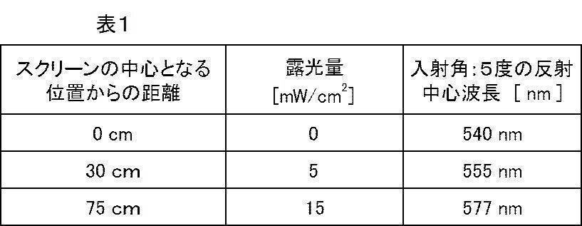
<比較例1>
実施例1と同様の方法で作製したアクリル層の上に、乾燥後の乾膜の厚みが4.0μmになるように室温にてワイヤーバーを用いて、重合性組成物塗布液2を塗布した。得られた塗膜を室温にて10秒間乾燥させた後、85℃の雰囲気で1分間加熱した。続いて、塗膜に対して、フュージョン製Dバルブ(ランプ90mW/cm2)の出力100%で5秒間、40℃にてUV照射し、反射層2を得た。
実施例1と同様の方法で作製したアクリル層の上に、乾燥後の乾膜の厚みが4.0μmになるように室温にてワイヤーバーを用いて、重合性組成物塗布液2を塗布した。得られた塗膜を室温にて10秒間乾燥させた後、85℃の雰囲気で1分間加熱した。続いて、塗膜に対して、フュージョン製Dバルブ(ランプ90mW/cm2)の出力100%で5秒間、40℃にてUV照射し、反射層2を得た。
JASCO製の分光光度計V-670を用いて、反射層2の所定位置における反射中心波長を求めた。結果を後述する表2に示す。
<評価>
反射層1および2をスクリーンとして用い、セイコーエプソン製プロジェクター(WB-546T)とスクリーン中央部を72cm離して設置し、緑色の映像を投影して色味変化を比較した。
なお、表2中の「投影光の入射角度」とは、上記プロジェクターを設置した位置とスクリーン上の各位置とを結んだ直線と、スクリーン表面の法線とのなす角を意図する。
また、表2中の「投影角度での反射波長」とは、上記「投影光の入射角度」にて各位置に入射した光のうち、反射された光の波長を表す。
反射層1および2をスクリーンとして用い、セイコーエプソン製プロジェクター(WB-546T)とスクリーン中央部を72cm離して設置し、緑色の映像を投影して色味変化を比較した。
なお、表2中の「投影光の入射角度」とは、上記プロジェクターを設置した位置とスクリーン上の各位置とを結んだ直線と、スクリーン表面の法線とのなす角を意図する。
また、表2中の「投影角度での反射波長」とは、上記「投影光の入射角度」にて各位置に入射した光のうち、反射された光の波長を表す。
反射層1は、スクリーンの中心部と端部(中心からの距離が遠い位置)とで反射波長が略同じであり、投影光の色味変化がほとんどなかった。
一方で、比較例である反射層2はスクリーンの端部において、緑色から青緑色への顕著な色味変化が観測され、さらに映像自体も暗くなってしまうことがわかった。
一方で、比較例である反射層2はスクリーンの端部において、緑色から青緑色への顕著な色味変化が観測され、さらに映像自体も暗くなってしまうことがわかった。
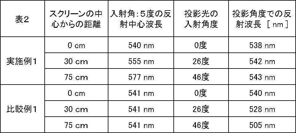
なお、実施例1における365nmのバンドパスフィルターを用いた態様の代わりに、図8に示すようにマスクの位置を徐々に変更して露光を行い、図2に示すような、一端から他端に向かってコレステリック液晶相の螺旋ピッチが変化している反射層を作製した。得られた反射層に対して、図3に示すように、上記プロジェクターを設置して緑色の映像を投影したところ、スクリーンの中心部と端部(中心からの距離が遠い位置)とで反射波長が略同じであり、投影光の色味変化がほとんどなかった。
また、実施例1における365nmのバンドパスフィルターを用いた態様の代わりに、図4のような中心部から端部に向かってコレステリック液晶相の螺旋ピッチが変化するような反射層が得られるフィルターを用いて、露光を行い、図4のような反射層を作製した。得られた反射層に対して、図5に示すように、上記プロジェクターを設置して緑色の映像を投影したところ、スクリーンの中心部と端部(中心からの距離が遠い位置)とで反射波長が略同じであり、投影光の色味変化がほとんどなかった。
また、実施例1における365nmのバンドパスフィルターを用いた態様の代わりに、図4のような中心部から端部に向かってコレステリック液晶相の螺旋ピッチが変化するような反射層が得られるフィルターを用いて、露光を行い、図4のような反射層を作製した。得られた反射層に対して、図5に示すように、上記プロジェクターを設置して緑色の映像を投影したところ、スクリーンの中心部と端部(中心からの距離が遠い位置)とで反射波長が略同じであり、投影光の色味変化がほとんどなかった。
10a,10b,100 投影部材
12 基板
14a,14b 反射層
16,102 投影装置
18 フィルター
20 塗膜
22 マスク
50a,50b 投影システム
12 基板
14a,14b 反射層
16,102 投影装置
18 フィルター
20 塗膜
22 マスク
50a,50b 投影システム
Claims (10)
- コレステリック液晶相を固定してなる反射層を有し、
前記反射層の面方向において、前記コレステリック液晶相の螺旋ピッチが徐々に変化する、投影部材。 - 前記反射層の中心部から端部に向かって、前記コレステリック液晶相の螺旋ピッチが徐々に大きくなる、請求項1に記載の投影部材。
- 前記反射層の一端から他端に向かって、前記コレステリック液晶相の螺旋ピッチが徐々に変化する、請求項1に記載の投影部材。
- 前記反射層表面において、前記反射層表面から離間して配置される投影装置の投影光出射口からの距離が長くなるに従って、前記コレステリック液晶相の螺旋ピッチが大きくなる、請求項1~3のいずれか1項に記載の投影部材。
- 前記反射層が、光拡散性を有する、請求項1~4のいずれか1項に記載の投影部材。
- 前記反射層が、光拡散要素を含む、請求項5に記載の投影部材。
- 前記反射層上に、さらに光拡散層を有する、請求項1~6のいずれか1項に記載の投影部材。
- 反射中心波長が異なる複数の前記反射層を有する、請求項1~7のいずれか1項に記載の投影部材。
- 請求項1~8のいずれか1項に記載の投影部材と、前記投影部材に投影光を出射する投影装置とを備える、投影システム。
- 請求項1~8のいずれか1項に記載の投影部材の製造方法であって、
重合性基を有する液晶化合物、および、光に感応しコレステリック液晶相の螺旋ピッチを変化させ得るキラル剤を含む組成物を用いて塗膜を形成し、前記塗膜を加熱して前記液晶化合物を配向させてコレステリック液晶相の状態とする工程と、
前記塗膜に光照射を施し、前記塗膜の面方向において、前記コレステリック液晶相の螺旋ピッチを変化させる工程と、
光照射が施された前記塗膜に対して硬化処理を施し、コレステリック液晶相を固定化してなる反射層を形成する工程と、を有する投影部材の製造方法。
Priority Applications (2)
| Application Number | Priority Date | Filing Date | Title |
|---|---|---|---|
| JP2018518241A JP6676159B2 (ja) | 2016-05-18 | 2017-05-10 | 投影部材、投影システム、投影部材の製造方法 |
| US16/191,897 US20190086786A1 (en) | 2016-05-18 | 2018-11-15 | Projection member, projection system, method of manufacturing projection member |
Applications Claiming Priority (2)
| Application Number | Priority Date | Filing Date | Title |
|---|---|---|---|
| JP2016099662 | 2016-05-18 | ||
| JP2016-099662 | 2016-05-18 |
Related Child Applications (1)
| Application Number | Title | Priority Date | Filing Date |
|---|---|---|---|
| US16/191,897 Continuation US20190086786A1 (en) | 2016-05-18 | 2018-11-15 | Projection member, projection system, method of manufacturing projection member |
Publications (1)
| Publication Number | Publication Date |
|---|---|
| WO2017199812A1 true WO2017199812A1 (ja) | 2017-11-23 |
Family
ID=60325826
Family Applications (1)
| Application Number | Title | Priority Date | Filing Date |
|---|---|---|---|
| PCT/JP2017/017683 Ceased WO2017199812A1 (ja) | 2016-05-18 | 2017-05-10 | 投影部材、投影システム、投影部材の製造方法 |
Country Status (3)
| Country | Link |
|---|---|
| US (1) | US20190086786A1 (ja) |
| JP (1) | JP6676159B2 (ja) |
| WO (1) | WO2017199812A1 (ja) |
Cited By (4)
| Publication number | Priority date | Publication date | Assignee | Title |
|---|---|---|---|---|
| WO2019131966A1 (ja) * | 2017-12-27 | 2019-07-04 | 富士フイルム株式会社 | 光学素子、導光素子および画像表示装置 |
| WO2019131950A1 (ja) * | 2017-12-27 | 2019-07-04 | 富士フイルム株式会社 | 光学素子およびセンサー |
| WO2019189818A1 (ja) * | 2018-03-29 | 2019-10-03 | 富士フイルム株式会社 | 光学素子、導光素子および画像表示装置 |
| WO2019189852A1 (ja) * | 2018-03-29 | 2019-10-03 | 富士フイルム株式会社 | 光学素子、導光素子および画像表示装置 |
Citations (8)
| Publication number | Priority date | Publication date | Assignee | Title |
|---|---|---|---|---|
| JP2003207632A (ja) * | 2002-01-11 | 2003-07-25 | Seiko Epson Corp | 反射板、反射板の製造方法、液晶装置、電子機器 |
| JP2004302075A (ja) * | 2003-03-31 | 2004-10-28 | Nitto Denko Corp | 広帯域コレステリック液晶フィルムの製造方法、円偏光板、直線偏光素子、照明装置および液晶表示装置 |
| JP2005091917A (ja) * | 2003-09-18 | 2005-04-07 | Dainippon Printing Co Ltd | 投影システム、それに用いられる投影スクリーン及び投影機ユニット |
| JP2005107083A (ja) * | 2003-09-30 | 2005-04-21 | Dainippon Printing Co Ltd | 投影システム |
| JP2006227581A (ja) * | 2005-01-21 | 2006-08-31 | Dainippon Printing Co Ltd | 透過反射両用投影スクリーン及びそれを備えた投影システム |
| US20070139766A1 (en) * | 2005-12-20 | 2007-06-21 | Radcliffe Marc D | High contrast front projection screen |
| JP2015141318A (ja) * | 2014-01-29 | 2015-08-03 | 富士フイルム株式会社 | 投映システムおよびプロジェクター |
| JP2017015897A (ja) * | 2015-06-30 | 2017-01-19 | 日本ゼオン株式会社 | 画像投射システム及び投影面部材 |
Family Cites Families (8)
| Publication number | Priority date | Publication date | Assignee | Title |
|---|---|---|---|---|
| US7158297B2 (en) * | 2003-09-19 | 2007-01-02 | Dai Nippon Printing Co., Ltd. | Projection screen and projection system comprising the same |
| US7158299B2 (en) * | 2003-09-26 | 2007-01-02 | Dai Nippon Printing Co., Ltd. | Projection screen and projection system comprising the same |
| KR101711144B1 (ko) * | 2010-10-05 | 2017-03-02 | 삼성전자주식회사 | 콜레스테릭 액정 디스플레이 장치 및 그 제조방법 |
| JP2016012084A (ja) * | 2014-06-30 | 2016-01-21 | 富士フイルム株式会社 | 液晶表示装置 |
| EP3163335A4 (en) * | 2014-06-30 | 2018-03-14 | Zeon Corporation | Identification medium, method for producing identification medium, and method for using identification medium |
| WO2016204067A1 (ja) * | 2015-06-15 | 2016-12-22 | 富士フイルム株式会社 | 3d表示用透明スクリーンおよび3d表示システム |
| WO2017191778A1 (ja) * | 2016-05-02 | 2017-11-09 | 富士フイルム株式会社 | 透明スクリーンおよび画像表示システム |
| KR102089204B1 (ko) * | 2016-05-24 | 2020-03-13 | 후지필름 가부시키가이샤 | 투명 필름, 투명 스크린 및 화상 표시 시스템과 투명 포스터 |
-
2017
- 2017-05-10 JP JP2018518241A patent/JP6676159B2/ja active Active
- 2017-05-10 WO PCT/JP2017/017683 patent/WO2017199812A1/ja not_active Ceased
-
2018
- 2018-11-15 US US16/191,897 patent/US20190086786A1/en not_active Abandoned
Patent Citations (8)
| Publication number | Priority date | Publication date | Assignee | Title |
|---|---|---|---|---|
| JP2003207632A (ja) * | 2002-01-11 | 2003-07-25 | Seiko Epson Corp | 反射板、反射板の製造方法、液晶装置、電子機器 |
| JP2004302075A (ja) * | 2003-03-31 | 2004-10-28 | Nitto Denko Corp | 広帯域コレステリック液晶フィルムの製造方法、円偏光板、直線偏光素子、照明装置および液晶表示装置 |
| JP2005091917A (ja) * | 2003-09-18 | 2005-04-07 | Dainippon Printing Co Ltd | 投影システム、それに用いられる投影スクリーン及び投影機ユニット |
| JP2005107083A (ja) * | 2003-09-30 | 2005-04-21 | Dainippon Printing Co Ltd | 投影システム |
| JP2006227581A (ja) * | 2005-01-21 | 2006-08-31 | Dainippon Printing Co Ltd | 透過反射両用投影スクリーン及びそれを備えた投影システム |
| US20070139766A1 (en) * | 2005-12-20 | 2007-06-21 | Radcliffe Marc D | High contrast front projection screen |
| JP2015141318A (ja) * | 2014-01-29 | 2015-08-03 | 富士フイルム株式会社 | 投映システムおよびプロジェクター |
| JP2017015897A (ja) * | 2015-06-30 | 2017-01-19 | 日本ゼオン株式会社 | 画像投射システム及び投影面部材 |
Cited By (18)
| Publication number | Priority date | Publication date | Assignee | Title |
|---|---|---|---|---|
| US11092730B2 (en) | 2017-12-27 | 2021-08-17 | Fujifilm Corporation | Optical element and sensor |
| US11435629B2 (en) | 2017-12-27 | 2022-09-06 | Fujifilm Corporation | Optical element, light guide element, and image display device |
| WO2019131966A1 (ja) * | 2017-12-27 | 2019-07-04 | 富士フイルム株式会社 | 光学素子、導光素子および画像表示装置 |
| JP7030847B2 (ja) | 2017-12-27 | 2022-03-07 | 富士フイルム株式会社 | 光学素子、導光素子および画像表示装置 |
| JPWO2019131950A1 (ja) * | 2017-12-27 | 2021-01-07 | 富士フイルム株式会社 | 光学素子およびセンサー |
| JPWO2019131966A1 (ja) * | 2017-12-27 | 2021-01-14 | 富士フイルム株式会社 | 光学素子、導光素子および画像表示装置 |
| WO2019131950A1 (ja) * | 2017-12-27 | 2019-07-04 | 富士フイルム株式会社 | 光学素子およびセンサー |
| JPWO2019189818A1 (ja) * | 2018-03-29 | 2021-04-01 | 富士フイルム株式会社 | 光学素子、導光素子および画像表示装置 |
| JPWO2019189852A1 (ja) * | 2018-03-29 | 2021-03-25 | 富士フイルム株式会社 | 光学素子、導光素子および画像表示装置 |
| JP2022025145A (ja) * | 2018-03-29 | 2022-02-09 | 富士フイルム株式会社 | 光学素子、導光素子および画像表示装置 |
| US11150517B2 (en) | 2018-03-29 | 2021-10-19 | Fujifilm Corporation | Optical element, light guide element, and image display device |
| WO2019189852A1 (ja) * | 2018-03-29 | 2019-10-03 | 富士フイルム株式会社 | 光学素子、導光素子および画像表示装置 |
| JP2022036995A (ja) * | 2018-03-29 | 2022-03-08 | 富士フイルム株式会社 | 光学素子、導光素子および画像表示装置 |
| WO2019189818A1 (ja) * | 2018-03-29 | 2019-10-03 | 富士フイルム株式会社 | 光学素子、導光素子および画像表示装置 |
| JP7232887B2 (ja) | 2018-03-29 | 2023-03-03 | 富士フイルム株式会社 | 光学素子、導光素子および画像表示装置 |
| JP7235839B2 (ja) | 2018-03-29 | 2023-03-08 | 富士フイルム株式会社 | 光学素子、導光素子および画像表示装置 |
| US11630308B2 (en) | 2018-03-29 | 2023-04-18 | Fujifilm Corporation | Optical element, light guide element, and image display device |
| US12360375B2 (en) | 2018-03-29 | 2025-07-15 | Fujifilm Corporation | Optical element, light guide element, and image display device |
Also Published As
| Publication number | Publication date |
|---|---|
| US20190086786A1 (en) | 2019-03-21 |
| JPWO2017199812A1 (ja) | 2019-03-28 |
| JP6676159B2 (ja) | 2020-04-08 |
Similar Documents
| Publication | Publication Date | Title |
|---|---|---|
| JP6336572B2 (ja) | 反射部材、投映スクリーン、コンバイナ、および、遮熱部材 | |
| JP7175995B2 (ja) | 光学積層体、導光素子および画像表示装置 | |
| JP6698875B2 (ja) | 光学フィルム | |
| JP6301350B2 (ja) | 投映像表示用ハーフミラーおよびその製造方法、ならびに投映像表示システム | |
| JP6321988B2 (ja) | 遮熱用途に使用可能な反射部材および反射部材を含むプロジェクター | |
| JPWO2017169696A1 (ja) | 反射層の製造方法および反射層 | |
| WO2017030176A1 (ja) | 投映システムおよび投映システムの中間像スクリーンの製造方法 | |
| JPWO2020071169A1 (ja) | ディスプレイ | |
| JP6676159B2 (ja) | 投影部材、投影システム、投影部材の製造方法 | |
| JP2018151636A (ja) | 投映像表示用ハーフミラーおよび投映像表示システム | |
| JP6286440B2 (ja) | 投映像表示用ハーフミラーおよび投映像表示システム | |
| JP6193471B2 (ja) | 投映像表示用部材および投映像表示用部材を含む投映システム | |
| JP6815491B2 (ja) | 透明スクリーンおよび映像投影システム | |
| CN115298608B (zh) | 反射屏幕、投影图像显示系统 | |
| JP6676154B2 (ja) | 透明スクリーンおよび画像表示システム | |
| JPWO2018193952A1 (ja) | 光学フィルム、積層型光学フィルムおよびこの積層型光学フィルムを備えた空中結像装置 | |
| JP7297870B2 (ja) | 光学部材、照明装置、および、スクリーン | |
| CN104062799A (zh) | 光学元件、投影式图像显示设备以及原始记录 | |
| JP4184186B2 (ja) | 投影スクリーン | |
| JP2018116308A (ja) | 遮熱用途に使用可能な反射部材および反射部材を含むプロジェクター | |
| WO2023190125A1 (ja) | リアプロジェクション用表示システム | |
| WO2017188251A1 (ja) | 透明スクリーンおよび画像表示システム | |
| JP2005037807A (ja) | 偏光選択反射層形成用塗工液、それを用いた投影スクリーンの製造方法および投影スクリーン | |
| JP2005062329A (ja) | 投影スクリーン | |
| JP2005084315A (ja) | 偏光選択反射層形成用塗工液および投影スクリーン |
Legal Events
| Date | Code | Title | Description |
|---|---|---|---|
| ENP | Entry into the national phase |
Ref document number: 2018518241 Country of ref document: JP Kind code of ref document: A |
|
| NENP | Non-entry into the national phase |
Ref country code: DE |
|
| 121 | Ep: the epo has been informed by wipo that ep was designated in this application |
Ref document number: 17799237 Country of ref document: EP Kind code of ref document: A1 |
|
| 122 | Ep: pct application non-entry in european phase |
Ref document number: 17799237 Country of ref document: EP Kind code of ref document: A1 |