WO2017199337A1 - 非接触給電方法及び非接触給電装置 - Google Patents
非接触給電方法及び非接触給電装置 Download PDFInfo
- Publication number
- WO2017199337A1 WO2017199337A1 PCT/JP2016/064614 JP2016064614W WO2017199337A1 WO 2017199337 A1 WO2017199337 A1 WO 2017199337A1 JP 2016064614 W JP2016064614 W JP 2016064614W WO 2017199337 A1 WO2017199337 A1 WO 2017199337A1
- Authority
- WO
- WIPO (PCT)
- Prior art keywords
- drive frequency
- frequency
- inverter
- output
- search circuit
- Prior art date
- Legal status (The legal status is an assumption and is not a legal conclusion. Google has not performed a legal analysis and makes no representation as to the accuracy of the status listed.)
- Ceased
Links
Images












Classifications
-
- H—ELECTRICITY
- H02—GENERATION; CONVERSION OR DISTRIBUTION OF ELECTRIC POWER
- H02J—ELECTRIC POWER NETWORKS; CIRCUIT ARRANGEMENTS OR SYSTEMS FOR SUPPLYING OR DISTRIBUTING ELECTRIC POWER; SYSTEMS FOR STORING ELECTRIC ENERGY
- H02J50/00—Circuit arrangements or systems for wireless supply or distribution of electric power
- H02J50/10—Circuit arrangements or systems for wireless supply or distribution of electric power using inductive coupling
-
- H—ELECTRICITY
- H02—GENERATION; CONVERSION OR DISTRIBUTION OF ELECTRIC POWER
- H02J—ELECTRIC POWER NETWORKS; CIRCUIT ARRANGEMENTS OR SYSTEMS FOR SUPPLYING OR DISTRIBUTING ELECTRIC POWER; SYSTEMS FOR STORING ELECTRIC ENERGY
- H02J50/00—Circuit arrangements or systems for wireless supply or distribution of electric power
- H02J50/80—Circuit arrangements or systems for wireless supply or distribution of electric power involving the exchange of data, concerning supply or distribution of electric power, between transmitting devices and receiving devices
Definitions
- the present invention relates to a contactless power feeding method and a contactless power feeding device.
- Patent Document 1 a technology for charging electric power output from a power feeding device to a battery of an electric vehicle in a contactless manner is known (Patent Document 1).
- Patent Document 1 the frequency of AC power is swept to set the resonance frequency.
- Patent Document 1 there is a problem that it takes time to search for the resonance frequency and thus takes time until the charging start time because the entire frequency region is swept.
- the present invention has been made in view of the above problems, and an object of the present invention is to provide a non-contact power feeding method and a non-contact power feeding apparatus that can reduce the time taken to detect the drive frequency. .
- a non-contact power supply method acquires a target output of an inverter before supplying power to a vehicle coil and detects an output phase of the inverter when the power transmission coil is excited with an output corresponding to the target output. If the output phase is smaller than the predetermined value, the drive frequency of the inverter is changed to a predetermined amount by a higher frequency.
- the time taken to detect the drive frequency can be shortened.
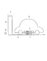
- FIG. 1A is an overall configuration diagram of a non-contact power feeding system including a non-contact power feeding apparatus and a vehicle according to an embodiment of the present invention.
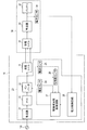
- FIG. 1B is a schematic configuration diagram of a contactless power feeding device and a vehicle according to an embodiment of the present invention.
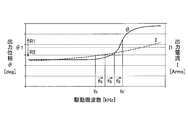
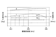
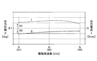
- FIG. 2 is a graph for explaining the basic operation of the drive frequency search circuit according to the embodiment of the present invention.
- FIG. 3A is a graph for explaining an operation example 1 of the drive frequency search circuit according to the embodiment of the present invention.
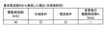
- FIG. 3B is a diagram illustrating a search result of the drive frequency search circuit according to the embodiment of the present invention.
- FIG. 3C is a diagram for explaining a search result of Comparative Example A.
- FIG. 3D is a diagram for explaining a search result of Comparative Example B.
- FIG. 4A is a graph for explaining an operation example 2 of the drive frequency search circuit according to the embodiment of the present invention.
- FIG. 4B is a diagram illustrating a search result of the drive frequency search circuit according to the embodiment of the present invention.
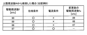
- FIG. 4C is a diagram for explaining a search result of Comparative Example A.
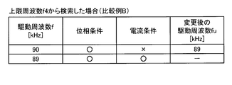
- FIG. 4D is a diagram illustrating search results of Comparative Example B.
- FIG. 5A is a graph for explaining an operation example 3 of the drive frequency search circuit according to the embodiment of the present invention.
- FIG. 5B is a diagram for explaining a search result of the drive frequency search circuit according to the embodiment of the present invention.
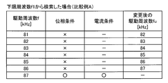
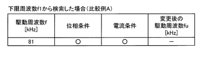
- FIG. 5C is a diagram for explaining a search result of Comparative Example A.
- FIG. 5D is a diagram for explaining a search result of Comparative Example B.
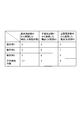
- FIG. 6 is a diagram illustrating search results of operation examples 1 to 3 of the drive frequency search circuit according to the embodiment of the present invention.
- FIG. 7A is a graph for explaining an operation example 4 of the drive frequency search circuit according to the embodiment of the present invention.
- FIG. 7B is a diagram for explaining a search result of the drive frequency search circuit according to the embodiment of the present invention.
- FIG. 8A is a graph for explaining an operation example 5 of the drive frequency search circuit according to the embodiment of the present invention.
- FIG. 8B is a diagram for explaining a search result of the drive frequency search circuit according to the embodiment of the present invention.
- FIG. 9A is a graph for explaining an operation example 6 of the drive frequency search circuit according to the embodiment of the present invention.
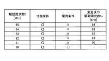
- FIG. 9B is a diagram illustrating a search result of the drive frequency search circuit according to the embodiment of the present invention.
- FIG. 10A is a graph for explaining an operation example 7 of the drive frequency search circuit according to the embodiment of the present invention.
- FIG. 10B is a diagram for explaining a search result of the drive frequency search circuit according to the embodiment of the present invention.
- FIG. 11A is a graph for explaining an operation example 8 of the drive frequency search circuit according to the embodiment of the present invention.
- FIG. 11B is a diagram illustrating a search result of the drive frequency search circuit according to the embodiment of the present invention.
- FIG. 12A is a flowchart for explaining an operation example of the drive frequency search circuit according to the embodiment of the present invention.
- FIG. 12B is a flowchart for explaining an operation example of the drive frequency search circuit according to the embodiment of the present invention.
- FIG. 12C is a flowchart for explaining an operation example of the drive frequency search circuit according to the embodiment of the present invention.
- FIG. 12D is a flowchart for explaining an operation example of the drive frequency search circuit according to the embodiment of the present invention.
- the non-contact electric power feeder 10 which concerns on this embodiment is demonstrated.
- the non-contact power supply device 10 is a device installed on the ground side such as a power supply stand or a parking lot, and includes a power transmission coil 11, a controller 20, and a cable 12.
- the cable 12 is a cable that connects the controller 20 and the power transmission coil 11, and is provided on a road surface such as a parking lot that includes the power transmission coil 11.
- the controller 20 converts AC power transmitted from the AC power source 100 into high-frequency AC power and supplies the power to the power transmission coil 11.
- the power transmission coil 11 supplies power in a non-contact manner to a power reception coil 31 (coil for vehicle) provided on the bottom surface of the vehicle 30.
- the controller 20 includes a rectifier 21, a PFC circuit 22, an inverter 23, a voltage sensor 24, a current sensor 25, a phase difference sensor 26, a drive frequency search circuit 27, and a power control circuit. 28.
- the rectifier 21 is electrically connected to the AC power source 100 and rectifies AC power from the AC power source 100.
- the PFC circuit 22 is a circuit for improving the power factor by shaping the output waveform from the rectifier 21, and is connected between the rectifier 21 and the inverter 23.
- the inverter 23 is a power conversion circuit including a PWM control circuit having a switching element such as an IGBT.
- the inverter 23 converts the DC power output from the PFC circuit 22 into high-frequency AC power and supplies it to the power transmission coil 11.
- the voltage sensor 24 detects the output voltage V of the inverter 23.
- the current sensor 25 detects the output current I of the inverter 23.
- the phase difference sensor 26 detects the output phase ⁇ of the output current I with respect to the output voltage V.
- the drive frequency search circuit 27 is a circuit that searches for a drive frequency for the inverter 23 to output the target output Pt. As will be described in detail later, the drive frequency search circuit 27 determines whether or not the output phase ⁇ and the output current I of the inverter 23 achieve limit values while changing the drive frequency of the inverter 23. When the output phase ⁇ and the output current I of the inverter 23 reach the limit values, the drive frequency search circuit 27 uses the drive frequency at that time as the drive frequency used during charging.
- the power control circuit 28 controls the target output Pt of the inverter 23 based on a signal received from the power sensor 34 described later.
- the power control circuit 28 transmits a signal related to the target output Pt to the drive frequency search circuit 27.
- the vehicle 30 includes a power receiving coil 31, a rectifier 32, a battery 33, and a power sensor 34.
- the rectifier 32 is connected to the power receiving coil 31, rectifies AC power received by the power receiving coil 31 into DC power, and supplies power to the battery 33.
- the power sensor 34 detects the power output from the rectifier 32 and transmits a power signal to the power control circuit 28. Note that data communication between the power sensor 34 and the power control circuit 28 can use wireless communication.
- the PFC circuit 22, the drive frequency search circuit 27, and the power control circuit 28 are computers composed of a CPU, a ROM, a RAM, a data bus connecting them, and an input / output interface, and follow a program stored in the ROM.
- the CPU performs a predetermined process.
- the left vertical axis represents the output phase ⁇ of the inverter 23
- the right vertical axis represents the output current I of the inverter 23
- the horizontal axis represents the drive frequency of the inverter 23.
- the drive frequency search circuit 27 excites the power transmission coil 11 while changing the drive frequency of the inverter 23 before starting charging of the battery 33 to perform test power transmission. At this time, the drive frequency search circuit 27 determines whether or not the drive frequency of the inverter 23 satisfies the drive condition of the inverter 23.
- the drive frequency search circuit 27 starts charging at the drive frequency. This point will be described with reference to FIG. As shown in FIG. 2, the drive frequency search circuit 27 sets the drive frequency of the inverter 23 to the basic frequency f0 before starting charging of the battery 33.
- the fundamental frequency f0 the median value of the drivable frequency band in consideration of radio interference with peripheral devices is used.
- the basic frequency f0 is described as 85 kHz.
- the drive frequency search circuit 27 excites the power transmission coil 11 at the basic frequency f0, and determines whether the output phase ⁇ and the output current I of the inverter 23 have reached the limit values.
- ⁇ 1 in FIG. 2 indicates a phase limit value
- I1 in FIG. 2 indicates a current limit value.
- the phase limit value ⁇ ⁇ b> 1 and the current limit value I ⁇ b> 1 are values related to the drive condition of the inverter 23. Specifically, if the output phase ⁇ of the inverter 23 is equal to or greater than the phase limit value ⁇ 1, the driving condition is satisfied. Further, if the output current I of the inverter 23 is equal to or less than the current limit value I1, the drive condition is satisfied.
- FIG. 2 is a region where the output phase ⁇ is equal to or greater than the phase limit value ⁇ 1, and a region R2 illustrated in FIG. 2 is a region where the output current I is equal to or less than the current limit value I1.
- the region R1 and the region R2 are the same in the following description.
- the drive frequency search circuit 27 first determines whether or not the output phase ⁇ of the inverter 23 has achieved the phase limit value ⁇ 1. When the output phase ⁇ of the inverter 23 has achieved the phase limit value ⁇ 1, the drive frequency search circuit 27 next determines whether or not the output current I of the inverter 23 has achieved the current limit value I1.
- the drive frequency search circuit 27 changes the basic frequency f0 to the predetermined amount fs and the high frequency side.
- the drive frequency search circuit 27 determines whether or not the output phase ⁇ of the inverter 23 has achieved the limit value at the changed drive frequency.
- the drive frequency search circuit 27 determines that the drive frequency f0 ′ is a drive frequency at which the output phase ⁇ of the inverter 23 achieves the limit value.
- the drive frequency search circuit 27 determines whether or not the output current I of the inverter 23 has reached the limit value at the drive frequency f0 '.
- the output current I of the inverter 23 is smaller than the current limit value I1 at the drive frequency f0 '.
- the drive frequency search circuit 27 determines that the drive frequency f0 ′ is a drive frequency at which the output current I of the inverter 23 achieves the limit value.
- the drive frequency search circuit 27 drives the inverter 23 at the drive frequency f0 ′, and the battery 33 Start charging.
- the reason why the drive frequency search circuit 27 first determines whether or not the output phase ⁇ has reached the limit value is that if the output phase ⁇ does not reach the limit value, there is a possibility that a malfunction may occur in the inverter 23. It is.
- the phase limit value ⁇ 1 (first predetermined value) and the current limit value I1 (second predetermined value) can be obtained based on experiments and simulations. For example, 0 degree may be used as the phase limit value ⁇ 1. In the following, the phase limit value ⁇ 1 and the current limit value I1 are simply expressed as limit values.
- the output current I of the inverter 23 has also reached the limit value at the drive frequency f0 ′ at which the output phase ⁇ of the inverter 23 has reached the limit value.
- the output phase ⁇ of the inverter 23 has the limit value.
- the drive frequency search circuit 27 changes the drive frequency to the predetermined amount fs and the low frequency side. Details of this point will be described later.
- the lower limit frequency f1 and the upper limit frequency f4 shown in FIG. 3A are the lower limit value and the upper limit value of the driveable frequency band in consideration of radio interference with peripheral devices.
- the lower limit frequency f1 is 81 kHz and the upper limit frequency f4 is 90 kHz.
- 3A is the lowest drive frequency among the drive frequencies at which the output phase ⁇ and the output current I achieve the limit values.
- 3A is the highest drive frequency among the drive frequencies at which the output phase ⁇ and the output current I achieve the limit values.
- the lower limit establishment frequency f2 is assumed to be 83.4 kHz
- the upper limit establishment frequency f3 is assumed to be 87.2 kHz.
- the drive frequency search circuit 27 ends the search for the drive frequency f.
- the output phase ⁇ of the inverter 23 reaches the limit value at the drive frequency of 84 kHz in the fourth search, and the output current I of the inverter 23 also reaches the limit value.
- the comparative example A ends the search for the driving frequency f.
- the comparative example B searches for the drive frequency f of the inverter 23 from the upper limit frequency f4, the output phase ⁇ of the inverter 23 achieves the limit value at the upper limit frequency f4.
- the output current I of the inverter 23 does not reach the limit value. Therefore, in the comparative example B, the upper limit frequency f4 is changed to the predetermined amount fs and the low frequency side, and this is repeated.
- the comparative example B ends the search for the driving frequency f.
- the drive frequency search circuit 27 searches for the drive frequency f from the basic frequency f0 as in the present embodiment
- the number of times of the search is the comparative example A and the comparative example. It can be seen that it is less than B.
- the lower limit establishment frequency f2 is assumed to be 86.8 kHz
- the upper limit establishment frequency f3 is assumed to be 89.2 kHz.
- the drive frequency search circuit 27 changes the basic frequency f0 to the predetermined amount fs and the high frequency side, and repeats this.
- the drive frequency search circuit 27 ends the search for the drive frequency f.
- the output phase ⁇ of the inverter 23 does not reach the limit value at the lower limit frequency f1. Therefore, in Comparative Example A, the lower limit frequency f1 is changed to the predetermined amount fs and the high frequency side, and this is repeated. As shown in FIG. 4C, at the drive frequency of 87 kHz in the seventh search, the output phase ⁇ of the inverter 23 achieves a limit value, and the output current I of the inverter 23 also reaches the limit value. Therefore, the comparative example A ends the search for the driving frequency f.
- the output phase ⁇ of the inverter 23 achieves the limit value, but the output current I of the inverter 23 does not reach the limit value. Therefore, in the comparative example B, the upper limit frequency f4 is changed to the predetermined amount fs and the low frequency side, and this is repeated. As shown in FIG. 4D, at the drive frequency of 89 kHz in the second search, the output phase ⁇ of the inverter 23 achieves the limit value, and the output current I of the inverter 23 also reaches the limit value. Therefore, the comparative example B ends the search for the driving frequency f.
- the lower limit establishment frequency f2 is assumed to be 82.3 kHz.
- the drive frequency search circuit 27 changes the basic frequency f0 to the predetermined amount fs and the low frequency side, and repeats this.
- the drive frequency search circuit 27 ends the search for the drive frequency f.
- the comparative example A ends the search for the driving frequency f.
- the output phase ⁇ of the inverter 23 achieves the limit value, but the output current I of the inverter 23 does not reach the limit value. Therefore, in the comparative example B, the upper limit frequency f4 is changed to the predetermined amount fs and the low frequency side, and this is repeated. As shown in FIG. 5D, at the drive frequency of 82 kHz in the ninth search, the output phase ⁇ of the inverter 23 achieves the limit value, and the output current I of the inverter 23 also reaches the limit value. Therefore, the comparative example B ends the search for the driving frequency f.
- FIG. 6 shows the results of the operation examples 1 to 3 shown in FIG. 3 to FIG.
- the drive frequency search circuit 27 searches for the drive frequency f from the basic frequency f 0
- the number of times required for the search is smaller than that of the comparative examples A and B on average.
- the drive frequency search circuit 27 searches for the drive frequency from the basic frequency f0
- the time required for the search is on average shorter than those of the comparative example A and the comparative example B, and thus the probability that the time required for the search can be shortened Will increase.
- the drive frequency search circuit 27 changes the basic frequency f0 to the low frequency side by a predetermined amount fs.
- the drive frequency search circuit 27 repeatedly changes the drive frequency f to the low frequency side, but the output current I of the inverter 23 does not achieve the limit value even when the drive frequency reaches the lower limit frequency f1.
- the drive frequency search circuit 27 changes the drive frequency f to the upper limit frequency f4.
- the output phase ⁇ of the inverter 23 reaches the limit value, and the output current I of the inverter 23 also reaches the limit value. Therefore, the drive frequency search circuit 27 ends the search for the drive frequency of the inverter 23.
- the drive frequency search circuit 27 changes the drive frequency f to the upper limit frequency f4, so that the time required for searching for the drive frequency f can be shortened. And the search range is not leaked.
- the drive frequency search circuit 27 changes the basic frequency f0 to the high frequency side by a predetermined amount fs.
- the drive frequency search circuit 27 repeatedly changes the drive frequency f to the high frequency side, but even if the drive frequency f reaches the upper limit frequency f4, the output phase ⁇ of the inverter 23 does not reach the limit value.
- the drive frequency search circuit 27 ends the search for the drive frequency f.
- the power control circuit 28 decreases the target output Pt. This avoids a situation where charging cannot be performed.
- the lower limit establishment frequency f2 is assumed to be 87.6 kHz
- the upper limit establishment frequency f3 is assumed to be 87.9 kHz.
- the drive frequency search circuit 27 changes the basic frequency f0 to the predetermined amount fs and the high frequency side, and repeats this.
- the output phase ⁇ of the inverter 23 reaches the limit value at the driving frequency of 88 kHz in the fourth search.
- the drive frequency search circuit 27 changes the drive frequency f to the low frequency side and searches for the drive frequency f at which the output current I of the inverter 23 achieves the limit value.
- the drive frequency search circuit 27 decreases the predetermined amount fs and changes the drive frequency f to the low frequency side. Specifically, the drive frequency search circuit 27 halves the predetermined amount fs (0.5 kHz) and changes the drive frequency f to the low frequency side.
- the output phase ⁇ of the inverter 23 does not reach the limit value at the frequency 87.5 kHz in the fifth search. Therefore, again, the drive frequency search circuit 27 changes the drive frequency f to the high frequency side, and searches for the drive frequency f at which the output phase ⁇ of the inverter 23 achieves the limit value. If the direction in which the drive frequency f is changed is changed once, the drive frequency search circuit 27 assumes that the direction has been changed again thereafter, and the drive frequency search circuit 27 determines the predetermined amount until the predetermined amount fs reaches the preset minimum amount fm. fs is decreased stepwise. Specifically, as shown in FIG.
- the drive frequency search circuit 27 changes the drive frequency f to the high frequency side by setting the predetermined amount fs to a quarter (0.25 kHz).
- the output phase ⁇ of the inverter 23 reaches the limit value, and the output current I of the inverter 23 also reaches the limit value. Therefore, the drive frequency search circuit 27 ends the search for the drive frequency f.
- the minimum amount fm is described as one-sixteenth of 1 kHz (0.0625 kHz).
- the lower limit establishment frequency f2 is assumed to be 82.1 kHz
- the upper limit establishment frequency f3 is assumed to be 82.3 kHz.
- the drive frequency search circuit 27 changes the basic frequency f0 to the predetermined amount fs and the low frequency side, and repeats this. As shown in FIG. 10B, the output phase ⁇ of the inverter 23 does not reach the limit value at the drive frequency of 82 kHz in the fourth search. Therefore, the drive frequency search circuit 27 changes the drive frequency f to the high frequency side. At this time, the direction of changing the drive frequency f changes from the low frequency side to the high frequency side. The drive frequency f is changed to the high frequency side by decreasing the predetermined amount fs. Specifically, the drive frequency search circuit 27 halves the predetermined amount fs (0.5 kHz) and changes the drive frequency f to the high frequency side.
- the drive frequency search circuit 27 again changes the direction in which the drive frequency f is changed from the high frequency side to the low frequency side. At this time, as shown in FIG. 10B, the drive frequency search circuit 27 changes the drive frequency f to the low frequency side by setting the predetermined amount fs to a quarter (0.25 kHz). At the driving frequency of 82.25 kHz in the sixth search, the output phase ⁇ of the inverter 23 reaches the limit value, and the output current I of the inverter 23 also reaches the limit value. Therefore, the drive frequency search circuit 27 ends the search for the drive frequency f.
- a drive frequency f5 shown in FIG. 11A is a drive frequency at which the output current I of the inverter 23 achieves the limit value
- a drive frequency f6 shown in FIG. 11A is a drive frequency at which the output phase ⁇ of the inverter 23 reaches the limit value. is there.
- the drive frequency f5 is assumed to be 85.8 kHz
- the drive frequency f6 is assumed to be 87.2 kHz.
- the drive frequency search circuit 27 changes the basic frequency f0 to the predetermined amount fs and the high frequency side, and repeats this.
- the output phase ⁇ of the inverter 23 reaches the limit value at the driving frequency of 88 kHz in the fourth search.
- the drive frequency search circuit 27 halves the predetermined amount fs (0.5 kHz) and changes the drive frequency f to the low frequency side.
- the drive frequency search circuit 27 changes the drive frequency f to the low frequency side by setting the predetermined amount fs to a quarter (0.25 kHz). Even at the driving frequency of 87.25 kHz in the sixth search, the output current I of the inverter 23 does not reach the limit value. Accordingly, the drive frequency search circuit 27 changes the drive frequency f to the low frequency side by setting the predetermined amount fs to 1/8 (0.125 kHz).
- the output phase ⁇ of the inverter 23 does not reach the limit value at the drive frequency of 87.125 kHz in the seventh search. Accordingly, the drive frequency search circuit 27 changes the drive frequency f to the high frequency side by setting the predetermined amount fs to 1/16 (0.0625 kHz). At the drive frequency of 87.1875 kHz in the eighth search, the output phase ⁇ of the inverter 23 does not reach the limit value.
- the drive frequency search circuit 27 ends the search for the drive frequency f of the inverter 23, and the power control circuit 28 decreases the target output Pt. This avoids a situation where charging cannot be performed.
- the reason why the search for the drive frequency f is terminated when the predetermined amount fs reaches the minimum amount fm is that there is a possibility that the drive frequency satisfying the drive condition can be searched even if the drive frequency is further refined. Because it is small.
- step S101 the drive frequency search circuit 27 acquires the target output Pt required when charging the battery 33.
- step S102 the drive frequency search circuit 27 transmits the basic frequency f0 and the target output Pt to the inverter 23.
- step S103 the inverter 23 excites the power transmission coil 11 with the output corresponding to the target output Pt using the fundamental frequency f0.
- step S104 the drive frequency search circuit 27 detects the output phase ⁇ and the output current I of the inverter 23.
- step S105 the drive frequency search circuit 27 determines whether or not the output phase ⁇ and the output current I of the inverter 23 have reached the limit values.
- the drive frequency search circuit 27 ends the search for the drive frequency f.
- the process proceeds to step S201.
- step S201 shown in FIG. 12B the drive frequency search circuit 27 determines whether or not the drive frequency f is the upper limit frequency f4. If the drive frequency f is the upper limit frequency f4 (Yes in step S201), the process proceeds to step S208. On the other hand, when the drive frequency f is not the upper limit frequency f4 (No in step S201), the process proceeds to step S202.
- step S202 the drive frequency search circuit 27 determines whether or not the drive frequency f is the basic frequency f0. If the drive frequency f is the fundamental frequency f0 (Yes in step S202), the process proceeds to step S203. On the other hand, when the drive frequency f is not the fundamental frequency f0 (No in step S202), the process proceeds to step S301.
- step S203 the drive frequency search circuit 27 determines whether or not the output phase ⁇ has reached the limit value. If the output phase ⁇ has reached the limit value (Yes in step S203), the process proceeds to step S204. On the other hand, when the output phase ⁇ does not reach the limit value (No in step S203), the process proceeds to step S205.
- step S204 the drive frequency search circuit 27 subtracts a predetermined amount fs from the drive frequency f, and calculates the changed drive frequency fu.
- step S205 the drive frequency search circuit 27 adds a predetermined amount fs to the drive frequency f, and calculates the changed drive frequency fu.
- step S206 the drive frequency search circuit 27 calculates the drive frequency f as the drive frequency fp before the change.
- step S207 the drive frequency search circuit 27 transmits the changed drive frequency fu to the inverter 23.
- step S208 the drive frequency search circuit 27 calculates the changed drive frequency fu as the upper limit frequency f4.
- step S209 the power control circuit 28 decreases the target output Pt.
- step S210 the drive frequency search circuit 27 transmits the changed drive frequency fu and the target output Pt lowered by the process in step S209 to the inverter 23.
- step S301 shown in FIG. 12C the drive frequency search circuit 27 determines whether or not the output phase ⁇ has reached the limit value. If the output phase ⁇ has reached the limit value (Yes in step S301), the process proceeds to step S302. On the other hand, when the output phase ⁇ does not reach the limit value (No in step S301), the process proceeds to step S401.
- step S302 the drive frequency search circuit 27 determines whether or not the drive frequency f is lower than the drive frequency fp before the change. If the drive frequency f is smaller than the drive frequency fp before the change (Yes in step S302), the process proceeds to step S303. On the other hand, when the drive frequency f is higher than the drive frequency fp before the change (No in step S302), the process proceeds to step S307.
- step S303 the drive frequency search circuit 27 determines whether or not the predetermined amount fs is the same as the absolute value of the value obtained by subtracting the drive frequency fp before the change from the drive frequency f. If the predetermined amount fs is the same as the absolute value of the value obtained by subtracting the drive frequency fp before the change from the drive frequency f (Yes in step S303), the process proceeds to step S304. On the other hand, when the predetermined amount fs is different from the absolute value of the value obtained by subtracting the drive frequency fp before the change from the drive frequency f (No in step S303), the process proceeds to step S307.
- step S304 the drive frequency search circuit 27 subtracts a predetermined amount fs from the drive frequency f, and calculates the changed drive frequency fu.
- step S305 the drive frequency search circuit 27 determines whether or not the changed drive frequency fu is smaller than the lower limit frequency f1. If the changed drive frequency fu is smaller than the lower limit frequency f1 (Yes in step S305), the process proceeds to step S306. On the other hand, when the changed drive frequency fu is equal to or higher than the lower limit frequency f1 (No in step S305), the process proceeds to step S309.
- step S306 the drive frequency search circuit 27 calculates the changed drive frequency fu as the upper limit frequency f4.
- step S307 the drive frequency search circuit 27 determines whether or not the absolute value of the value obtained by subtracting the drive frequency fp before the change from the drive frequency f is equal to or greater than the minimum amount fm. If the absolute value of the value obtained by subtracting the drive frequency fp before the change from the drive frequency f is equal to or greater than the minimum amount fm (Yes in step S307), the process proceeds to step S308. On the other hand, when the absolute value of the value obtained by subtracting the drive frequency fp before the change from the drive frequency f is smaller than the minimum amount fm (No in step S307), the process proceeds to step S311.
- step S308 the drive frequency search circuit 27 halves the absolute value of the value obtained by subtracting the drive frequency fp before the change from the drive frequency f. Then, the drive frequency search circuit 27 subtracts the value halved from the drive frequency f, and calculates the changed drive frequency fu.
- step S309 the drive frequency search circuit 27 calculates the drive frequency f as the drive frequency fp before the change.
- step S310 the drive frequency search circuit 27 transmits the changed drive frequency fu to the inverter 23.
- step S311 the power control circuit 28 decreases the target output Pt.
- step S312 the drive frequency search circuit 27 transmits the target output Pt lowered by the process in step S311 to the inverter 23.
- step S401 shown in FIG. 12D the drive frequency search circuit 27 determines whether or not the drive frequency f is smaller than the drive frequency fp before the change. If the drive frequency f is smaller than the drive frequency fp before the change (Yes in step S401), the process proceeds to step S404. On the other hand, when the drive frequency f is higher than the drive frequency fp before the change (No in step S401), the process proceeds to step S402.
- step S402 the drive frequency search circuit 27 determines whether or not the predetermined amount fs is the same as the absolute value of a value obtained by subtracting the drive frequency fp before the change from the drive frequency f.
- the predetermined amount fs is the same as the absolute value of the value obtained by subtracting the drive frequency fp before the change from the drive frequency f (Yes in step S402)
- the process proceeds to step S403.
- the predetermined amount fs is different from the absolute value of the value obtained by subtracting the drive frequency fp before the change from the drive frequency f (No in step S402)
- the process proceeds to step S404.
- step S403 the drive frequency search circuit 27 adds a predetermined amount fs to the drive frequency f, and calculates the changed drive frequency fu.
- step S404 the drive frequency search circuit 27 determines whether or not the absolute value of the value obtained by subtracting the drive frequency fp before the change from the drive frequency f is equal to or greater than the minimum amount fm. If the absolute value of the value obtained by subtracting the drive frequency fp before the change from the drive frequency f is equal to or greater than the minimum amount fm (Yes in step S404), the process proceeds to step S405. On the other hand, when the absolute value of the value obtained by subtracting the drive frequency fp before the change from the drive frequency f is smaller than the minimum amount fm (No in step S404), the process proceeds to step S408.
- step S405 the drive frequency search circuit 27 halves the absolute value of the value obtained by subtracting the drive frequency fp before the change from the drive frequency f. Then, the drive frequency search circuit 27 adds the half value to the drive frequency f, and calculates the changed drive frequency fu.
- step S406 the drive frequency search circuit 27 calculates the drive frequency f as the drive frequency fp before the change.
- step S407 the drive frequency search circuit 27 transmits the changed drive frequency fu to the inverter 23.
- step S408 the power control circuit 28 decreases the target output Pt.
- step S409 the drive frequency search circuit 27 transmits the target output Pt lowered by the process in step S408 to the inverter 23.
- the drive frequency search circuit 27 acquires the target output Pt before charging the battery 33, drives the inverter 23 at the basic frequency f0, and outputs the target output Pt. At this time, the drive frequency search circuit 27 detects the output phase ⁇ of the inverter 23 and determines whether or not the output phase ⁇ of the inverter 23 has reached the limit value. When the output phase ⁇ of the inverter 23 does not reach the limit value, the drive frequency search circuit 27 changes the drive frequency f from the predetermined amount fs and the basic frequency f0 to the high frequency side, and the output phase ⁇ of the inverter 23 reaches the limit value. Search for the drive frequency f to be achieved. As a result, the drive frequency search circuit 27 can detect the drive frequency f by searching the high frequency side from the basic frequency f0, so that the time required for detection can be shortened compared to the case of searching all the drive frequencies at random. Probability increases.
- the drive frequency search circuit 27 determines whether the output current I of the inverter 23 has reached the limit value when the output phase ⁇ of the inverter 23 has reached the limit value. When the output current I of the inverter 23 does not achieve the limit value, the drive frequency search circuit 27 changes the drive frequency f to the predetermined amount fs and the low frequency side, and the drive frequency at which the output current I of the inverter 23 reaches the limit value. Search for f. Thereby, since the drive frequency search circuit 27 can search the low frequency side and detect the drive frequency f, the probability that the time required for detection can be shortened is increased as compared with a case where all the drive frequencies are randomly searched.
- the drive frequency search circuit 27 sets the drive frequency f to the upper limit. Change to frequency f4. As a result, the probability that the time required for searching for the drive frequency f can be shortened increases, and the search range is not leaked.
- the drive frequency search circuit 27 ends the search for the drive frequency f, and the power control circuit 28 decreases the target output Pt. This avoids a situation where charging cannot be performed.
- the driving frequency search circuit 27 decreases the predetermined amount fs to reduce the driving frequency f. change.
- the drive frequency search circuit 27 searches the drive frequency f by reducing the predetermined amount fs. This increases the probability that the drive frequency f that satisfies the drive condition of the inverter 23 can be searched.
- the drive frequency search circuit 27 ends the search for the drive frequency f, and the power control circuit 28 decreases the target output Pt. This avoids a situation where charging cannot be performed.
- the drive frequency search circuit 27 of the present embodiment determines whether or not the output current I of the inverter 23 has reached the limit value after the output phase ⁇ of the inverter 23 has reached the limit value, but is not limited thereto. For example, the drive frequency search circuit 27 may determine whether the output power or the output voltage V of the inverter 23 has reached the limit value instead of the output current I after the output phase ⁇ has reached the limit value. Good. The drive frequency search circuit 27 may determine whether the output power or the output voltage V has reached the limit value in addition to the output current I after the output phase ⁇ has reached the limit value. The drive frequency search circuit 27 may determine whether or not the output current I, the output power, and the output voltage V have reached the limit value after the output phase ⁇ has reached the limit value. If the output power or the output voltage V has not reached the limit value, the drive frequency search circuit 27 may change the drive frequency f to the predetermined amount fs and the low frequency side in the same manner as the output current I.
- the drive frequency search circuit 27 may transmit the target output Pt to the inverter 23 while increasing the target output Pt stepwise. Thereby, the drive frequency search circuit 27 can drive the inverter 23 more safely.
- the drive frequency search circuit 27 is halved when the predetermined amount fs is decreased stepwise, but is not limited thereto.
- the drive frequency search circuit 27 may reduce the predetermined amount fs while reducing it to one third, or may decrease it while decreasing the predetermined value.
- the minimum amount fm has been described as 0.0625 kHz.
- the present invention is not limited to this, and the minimum amount fm can be changed as appropriate.
- the processing circuit includes a programmed processing device such as a processing device including an electrical circuit.
- the processing circuitry also includes devices such as application specific integrated circuits (ASICs) and conventional circuit components arranged to perform the functions described in the embodiments.
- ASICs application specific integrated circuits
- Non-contact electric power feeder 11 Power transmission coil 12 Cable 20 Controller 21 Rectifier 22 PFC circuit 23 Inverter 24 Voltage sensor 25 Current sensor 26 Phase difference sensor 27 Drive frequency search circuit 28 Power control circuit 30 Vehicle 31 Power reception coil 32 Rectifier 33 Battery 34 Power sensor 100 AC power supply
Landscapes
- Engineering & Computer Science (AREA)
- Computer Networks & Wireless Communication (AREA)
- Power Engineering (AREA)
- Electric Propulsion And Braking For Vehicles (AREA)
Abstract
受電コイル(31)に給電する送電コイル(11)と、送電コイル(11)を励磁するインバータ(23)と、を備える非接触給電装置(10)の非接触給電方法であって、 受電コイル(31)に給電する前に、インバータ(23)の目標出力を取得し、目標出力に対応する出力で送電コイル(11)を励磁した際のインバータ(23)の出力位相を検出し、出力位相が所定値より小さい場合、インバータ(23)の駆動周波数を所定量、高周波数側に変更する。
Description
本発明は、非接触給電方法及び非接触給電装置に関する。
従来より、給電装置から出力される電力を非接触で電気自動車のバッテリに充電する技術が知られている(特許文献1)。特許文献1では、交流電力の周波数をスイープして共鳴周波数を設定する。
しかしながら、特許文献1では、全周波数領域をスイープするため、共鳴周波数の検索に時間がかかり、ひいては充電開始時間までに時間がかかるという問題があった。
本発明は、上記問題に鑑みて成されたものであり、その目的は、駆動周波数を検出するまでにかかる時間を短縮することができる非接触給電方法及び非接触給電装置を提供することにある。
本発明の一態様に係る非接触給電方法は、車両用コイルに給電する前に、インバータの目標出力を取得し、目標出力に対応する出力で送電コイルを励磁した際のインバータの出力位相を検出し、出力位相が所定値より小さい場合、インバータの駆動周波数を所定量、高周波数側に変更する。
本発明によれば、駆動周波数を検出するまでにかかる時間を短縮することができる。
以下、本発明の実施形態について、図面を参照して説明する。図面の記載において同一部分には同一符号を付して説明を省略する。
図1を参照して、本実施形態に係る非接触給電装置10について説明する。
非接触給電装置10は、給電スタンドや駐車場などの地上側に設置される装置であり、送電コイル11と、コントローラ20と、ケーブル12とを備える。ケーブル12は、コントローラ20と送電コイル11とを接続するケーブルであり、送電コイル11を備えた駐車場などの路面に設けられる。コントローラ20は、交流電源100から送電される交流電力を高周波の交流電力に変換し、送電コイル11に電力を供給する。送電コイル11は、車両30の底面に設けられる受電コイル31(車両用コイル)へ非接触で電力を供給する。
次に図1Bを参照して、図1Aに示した構成の詳細を説明する。
図1Bに示すように、コントローラ20は、整流器21と、PFC回路22と、インバータ23と、電圧センサ24と、電流センサ25と、位相差センサ26と、駆動周波数検索回路27と、電力制御回路28とを備える。
整流器21は、交流電源100に電気的に接続され、交流電源100からの交流電力を整流する。
PFC回路22は、整流器21からの出力波形を整形することで力率を改善するための回路であり、整流器21とインバータ23との間に接続される。
インバータ23は、IGBT等のスイッチング素子を有したPWM制御回路を含む電力変換回路である。インバータ23は、PFC回路22から出力される直流電力を高周波の交流電力に変換し、送電コイル11に供給する。
電圧センサ24は、インバータ23の出力電圧Vを検出する。電流センサ25は、インバータ23の出力電流Iを検出する。位相差センサ26は、出力電圧Vに対する出力電流Iの出力位相θを検出する。これらのセンサは、検出したデータを駆動周波数検索回路27に出力する。
駆動周波数検索回路27は、インバータ23が目標出力Ptを出力するための駆動周波数を検索する回路である。詳しくは後述するが、駆動周波数検索回路27は、インバータ23の駆動周波数を変更しながら、インバータ23の出力位相θ及び出力電流Iが制限値を達成するか否かを判定する。そして、駆動周波数検索回路27は、インバータ23の出力位相θ及び出力電流Iが制限値を達成した場合、そのときの駆動周波数を充電時に使用する駆動周波数として用いる。
電力制御回路28は、後述する電力センサ34から受信した信号に基づいてインバータ23の目標出力Ptを制御する。電力制御回路28は、目標出力Ptに係る信号を駆動周波数検索回路27に送信する。
車両30は、受電コイル31と、整流器32と、バッテリ33と、電力センサ34とを備える。
整流器32は、受電コイル31に接続され、受電コイル31で受電された交流電力を直流電力に整流し、バッテリ33に電力を供給する。
電力センサ34は、整流器32から出力される電力を検出し、電力制御回路28に電力信号を送信する。なお、電力センサ34と電力制御回路28とのデータのやりとりは、無線通信を用いることができる。
なお、PFC回路22、駆動周波数検索回路27、及び電力制御回路28は、CPU、ROM、RAMおよびそれらを接続するデータバスと入出力インターフェースから構成されるコンピュータであり、ROMに格納されたプログラムに従い、CPUが所定の処理を行う。
次に、図2を参照して、本実施形態の駆動周波数検索回路27の基本動作を説明する。図2において、左縦軸はインバータ23の出力位相θを示し、右縦軸はインバータ23の出力電流Iを示し、横軸はインバータ23の駆動周波数を示す。駆動周波数検索回路27は、バッテリ33の充電を開始する前に、インバータ23の駆動周波数を変更しながら送電コイル11を励磁して、試験送電を行う。このとき、駆動周波数検索回路27は、インバータ23の駆動周波数がインバータ23の駆動条件を満たすか否かを判定する。そして、駆動周波数検索回路27は、インバータ23の駆動周波数がインバータ23の駆動条件を満たす場合に、その駆動周波数で充電を開始する。この点について、図2を参照して説明する。図2に示すように、駆動周波数検索回路27は、バッテリ33の充電を開始する前に、インバータ23の駆動周波数を基本周波数f0に設定する。基本周波数f0は、周辺機器との電波障害を考慮した駆動可能周波数帯の中央値を用いる。本実施形態では、基本周波数f0を85kHzとして説明する。
駆動周波数検索回路27は、基本周波数f0で送電コイル11を励磁し、インバータ23の出力位相θ、出力電流Iが制限値を達成したか否かを判定する。ここで、図2のθ1は、位相制限値を示し、図2のI1は、電流制限値を示す。位相制限値θ1、及び電流制限値I1は、インバータ23の駆動条件に関する値である。具体的には、インバータ23の出力位相θは、位相制限値θ1以上であれば、駆動条件を満たす。また、インバータ23の出力電流Iは、電流制限値I1以下であれば、駆動条件を満たす。図2に示す領域R1は、出力位相θが位相制限値θ1以上となる領域であり、図2に示す領域R2は、出力電流Iが電流制限値I1以下となる領域である。領域R1及び領域R2は、以下の説明においても同様である。
駆動周波数検索回路27は、最初にインバータ23の出力位相θが位相制限値θ1を達成したか否かを判定する。インバータ23の出力位相θが位相制限値θ1を達成した場合、次に駆動周波数検索回路27は、インバータ23の出力電流Iが電流制限値I1を達成したか否かを判定する。
図2に示す例では、基本周波数f0において、インバータ23の出力位相θは、位相制限値θ1より小さいため、制限値を達成しない。この場合、駆動周波数検索回路27は、基本周波数f0を所定量fs、高周波数側に変更する。次に、駆動周波数検索回路27は、変更後の駆動周波数において、インバータ23の出力位相θが、制限値を達成したか否かを判定する。図2に示す例では、駆動周波数検索回路27が所定量fsで3回、高周波数側に変更した場合、インバータ23の出力位相θが、位相制限値θ1より大きくなる。このため、駆動周波数検索回路27は、駆動周波数f0’を、インバータ23の出力位相θが制限値を達成する駆動周波数であると判定する。
次に、駆動周波数検索回路27は、駆動周波数f0’において、インバータ23の出力電流Iが制限値を達成したか否かを判定する。図2に示す例では、駆動周波数f0’において、インバータ23の出力電流Iは、電流制限値I1より小さい。このため、駆動周波数検索回路27は、駆動周波数f0’を、インバータ23の出力電流Iが制限値を達成する駆動周波数であると判定する。以上説明したように、駆動周波数f0’において、インバータ23の出力位相θ及び出力電流Iが制限値を達成するため、駆動周波数検索回路27は、駆動周波数f0’でインバータ23を駆動させ、バッテリ33の充電を開始する。なお、駆動周波数検索回路27が最初に出力位相θが制限値を達成したか否かを判定する理由は、出力位相θが制限値を達成しない場合、インバータ23に不具合が発生するおそれがあるためである。なお、位相制限値θ1(第1所定値)、及び電流制限値I1(第2所定値)は、実験やシミュレーションに基づいて求めることができる。位相制限値θ1は、例えば0度を用いてもよい。また、以下において、位相制限値θ1及び電流制限値I1を単に制限値と表現する。
なお、図2に示す例では、インバータ23の出力位相θが制限値を達成する駆動周波数f0’において、インバータ23の出力電流Iも制限値を達成したが、インバータ23の出力位相θが制限値を達成する駆動周波数において、インバータ23の出力電流Iが制限値を達成しない場合がある。この場合、駆動周波数検索回路27は、駆動周波数を所定量fs、低周波数側に変更する。この点の詳細は、後述する。
次に図3~図5を参照して、駆動周波数検索回路27の動作例と、駆動周波数の検索を開始する場所を変更した比較例A及び比較例Bについて説明する。
図3Aに示す下限周波数f1、及び上限周波数f4は、周辺機器との電波障害を考慮した駆動可能周波数帯の下限値及び上限値である。本実施形態では、下限周波数f1を81kHz、上限周波数f4を90kHzとして説明する。また、図3Aに示す下限成立周波数f2は、出力位相θ及び出力電流Iが制限値を達成する駆動周波数のうち、一番低い駆動周波数である。また、図3Aに示す上限成立周波数f3は、出力位相θ及び出力電流Iが制限値を達成する駆動周波数のうち、一番高い駆動周波数である。図3Aに示す例では、下限成立周波数f2を83.4kHz、上限成立周波数f3を87.2kHzとして説明する。
図3A、及び図3Bに示すように、基本周波数f0において、インバータ23の出力位相θは制限値を達成し、インバータ23の出力電流Iも制限値を達成する。よって、駆動周波数検索回路27は、駆動周波数fの検索を終了する。
一方、図3A、及び図3Cに示すように、比較例Aが下限周波数f1からインバータ23の駆動周波数fを検索する場合、下限周波数f1において、インバータ23の出力位相θは制限値を達成しない。そこで、比較例Aは、下限周波数f1を所定量fs、高周波数側に変更する。なお、所定量fsは、1kHzとして説明する。以下においても同様である。すなわち、変更後の駆動周波数fu(2回目の検索に用いる駆動周波数)は、82kHzとなる。比較例Aは、これを繰り返し実行し、図3Cに示すように、4回目の検索における駆動周波数84kHzにおいて、インバータ23の出力位相θは制限値を達成し、インバータ23の出力電流Iも制限値を達成する。よって、比較例Aは、駆動周波数fの検索を終了する。
一方、図3A、及び図3Dに示すように、比較例Bが上限周波数f4からインバータ23の駆動周波数fを検索する場合、上限周波数f4において、インバータ23の出力位相θは制限値を達成するが、インバータ23の出力電流Iは制限値を達成しない。そこで、比較例Bは、上限周波数f4を所定量fs、低周波数側に変更し、これを繰り返す。図3Dに示すように、4回目の検索における駆動周波数87kHzにおいて、インバータ23の出力位相θは制限値を達成し、インバータ23の出力電流Iも制限値を達成する。よって、比較例Bは、駆動周波数fの検索を終了する。
以上説明したように、図3に示す例では、本実施形態のように、駆動周波数検索回路27が基本周波数f0から駆動周波数fを検索した場合、検索にかかる回数は、比較例A及び比較例Bより少ないことがわかる。
次に、図4を参照して、動作例2について説明する。図4Aに示す例では、下限成立周波数f2を86.8kHz、上限成立周波数f3を89.2kHzとして説明する。
図4A、及び図4Bに示すように、基本周波数f0において、インバータ23の出力位相θは制限値を達成しない。そこで、駆動周波数検索回路27は、基本周波数f0を所定量fs、高周波数側に変更し、これを繰り返す。図4Bに示すように、3回目の検索における駆動周波数87kHzにおいて、インバータ23の出力位相θは制限値を達成し、インバータ23の出力電流Iも制限値を達成する。よって、駆動周波数検索回路27は、駆動周波数fの検索を終了する。
一方、図4A、及び図4Cに示すように、下限周波数f1において、インバータ23の出力位相θは制限値を達成しない。そこで、比較例Aは、下限周波数f1を所定量fs、高周波数側に変更し、これを繰り返す。図4Cに示すように、7回目の検索における駆動周波数87kHzにおいて、インバータ23の出力位相θは制限値を達成し、インバータ23の出力電流Iも制限値を達成する。よって、比較例Aは、駆動周波数fの検索を終了する。
一方、図4A、及び図4Dに示すように、上限周波数f4において、インバータ23の出力位相θは制限値を達成するが、インバータ23の出力電流Iは制限値を達成しない。そこで、比較例Bは、上限周波数f4を所定量fs、低周波数側に変更し、これを繰り返す。図4Dに示すように、2回目の検索における駆動周波数89kHzにおいて、インバータ23の出力位相θは制限値を達成し、インバータ23の出力電流Iも制限値を達成する。よって、比較例Bは、駆動周波数fの検索を終了する。
以上説明したように、図4に示す動作例2では、本実施形態のように、駆動周波数検索回路27が基本周波数f0から駆動周波数fを検索した場合、検索にかかる回数は、比較例Aより少なく、比較例Bより多いことがわかる。
次に、図5を参照して、動作例3について説明する。図5Aに示す例では、下限成立周波数f2を82.3kHzとして説明する。
図5A、及び図5Bに示すように、基本周波数f0において、インバータ23の出力位相θは制限値を達成するが、インバータ23の出力電流Iは制限値を達成しない。そこで、駆動周波数検索回路27は、基本周波数f0を所定量fs、低周波数側に変更し、これを繰り返す。図5Bに示すように、4回目の検索における駆動周波数82kHzにおいて、インバータ23の出力位相θは制限値を達成し、インバータ23の出力電流Iも制限値を達成する。よって、駆動周波数検索回路27は、駆動周波数fの検索を終了する。
一方、図5A、及び図5Cに示すように、下限周波数f1において、インバータ23の出力位相θは制限値を達成し、インバータ23の出力電流Iも制限値を達成する。よって、比較例Aは、駆動周波数fの検索を終了する。
一方、図5A、及び図5Dに示すように、上限周波数f4において、インバータ23の出力位相θは制限値を達成するが、インバータ23の出力電流Iは制限値を達成しない。そこで、比較例Bは、上限周波数f4を所定量fs、低周波数側に変更し、これを繰り返す。図5Dに示すように、9回目の検索における駆動周波数82kHzにおいて、インバータ23の出力位相θは制限値を達成し、インバータ23の出力電流Iも制限値を達成する。よって、比較例Bは、駆動周波数fの検索を終了する。
以上説明したように、図5に示す動作例3では、本実施形態のように、駆動周波数検索回路27が基本周波数f0から駆動周波数fを検索した場合、検索にかかる回数は、比較例Aより多く、比較例Bより少ないことがわかる。
図3~図5に示す動作例1~3をまとめた結果を図6に示す。図6に示すように、駆動周波数検索回路27が基本周波数f0から駆動周波数fを検索した場合、検索にかかる回数が比較例A及び比較例Bより平均的に少ないことがわかる。換言すれば、駆動周波数検索回路27が基本周波数f0から駆動周波数を検索することにより、検索にかかる時間が比較例A及び比較例Bより平均的に短くなるため、検索にかかる時間を短縮できる確率が高まる。
次に、図7を参照して、駆動周波数検索回路27の動作例4について説明する。
図7A、及び図7Bに示すように、基本周波数f0において、インバータ23の出力位相θは制限値を達成するが、インバータ23の出力電流Iは制限値を達成しない。そこで、駆動周波数検索回路27は、基本周波数f0を所定量fs、低周波数側に変更する。駆動周波数検索回路27は、駆動周波数fを低周波数側に繰り返し変更するが、駆動周波数が下限周波数f1に到達してもインバータ23の出力電流Iは制限値を達成しない。このような場合、駆動可能周波数帯にインバータ23の駆動条件を満たす駆動周波数が存在することを期待し、基本周波数f0から所定量fs、高周波数側に変更して駆動周波数fを検索することが考えられる。しかしながら、この方法は、特許文献1のように駆動可能周波数帯の全体を検索することになるため、検索完了までに時間がかかってしまう。
そこで、駆動周波数fが下限周波数f1に到達し、次の変更後の駆動周波数fuが下限周波数f1より低くなる場合、駆動周波数検索回路27は、駆動周波数fを上限周波数f4に変更する。上限周波数f4において、インバータ23の出力位相θは制限値を達成し、インバータ23の出力電流Iも制限値を達成する。よって、駆動周波数検索回路27は、インバータ23の駆動周波数の検索を終了する。このように、変更後の駆動周波数fuが下限周波数f1より低くなる場合、駆動周波数検索回路27が駆動周波数fを上限周波数f4に変更することにより、駆動周波数fの検索にかかる時間を短縮できる確率が高まり、検索範囲の漏れがなくなる。
次に、図8を参照して、駆動周波数検索回路27の動作例5について説明する。
図8A、及び図8Bに示すように、基本周波数f0において、インバータ23の出力位相θは制限値を達成しない。そこで、駆動周波数検索回路27は、基本周波数f0を所定量fs、高周波数側に変更する。駆動周波数検索回路27は、駆動周波数fを高周波数側に繰り返し変更するが、駆動周波数fが上限周波数f4に到達してもインバータ23の出力位相θは制限値を達成しない。駆動周波数fが上限周波数f4に到達し、次の変更後の駆動周波数fuが上限周波数f4より高くなる場合、駆動周波数検索回路27は、駆動周波数fの検索を終了する。このように駆動周波数検索回路27が目標出力Ptを満たす駆動周波数fを検索できない場合、電力制御回路28は、目標出力Ptを下げる。これにより、充電ができなくなる事態は回避される。
次に、図9を参照して、駆動周波数検索回路27の動作例6を説明する。図9Aに示す例では、下限成立周波数f2を87.6kHz、上限成立周波数f3を87.9kHzとして説明する。
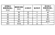
図9A、及び図9Bに示すように、基本周波数f0において、インバータ23の出力位相θは制限値を達成しない。そこで、駆動周波数検索回路27は、基本周波数f0を所定量fs、高周波数側に変更し、これを繰り返す。図9Bに示すように、4回目の検索における駆動周波数88kHzにおいて、インバータ23の出力位相θは制限値を達成する。しかし、駆動周波数88kHzにおいて、インバータ23の出力電流Iは制限値を達成しない。そこで、駆動周波数検索回路27は、駆動周波数fを低周波数側に変更して、インバータ23の出力電流Iが制限値を達成する駆動周波数fを検索する。このとき、駆動周波数fを変更する向きが、高周波数側から低周波数側に変わる。駆動周波数fを変更する向きが変わった場合、駆動周波数検索回路27は、所定量fsを小さくして駆動周波数fを低周波数側に変更する。具体的には、駆動周波数検索回路27は、所定量fsを半分(0.5kHz)にして、駆動周波数fを低周波数側に変更する。
5回目の検索における周波数87.5kHzにおいて、インバータ23の出力位相θは制限値を達成しない。そこで再度、駆動周波数検索回路27は、駆動周波数fを高周波数側に変更して、インバータ23の出力位相θが制限値を達成する駆動周波数fを検索する。なお、駆動周波数fを変更する向きが一度変わった場合、その後に再度向きが変更になったとして、駆動周波数検索回路27は、所定量fsが予め設定された最小量fmに到達するまで所定量fsを段階的に小さくする。具体的には、図9Bに示すように、駆動周波数検索回路27は、所定量fsを四分の一(0.25kHz)にして、駆動周波数fを高周波数側に変更する。6回目の検索における駆動周波数87.75kHzにおいて、インバータ23の出力位相θは制限値を達成し、インバータ23の出力電流Iも制限値を達成する。よって、駆動周波数検索回路27は、駆動周波数fの検索を終了する。なお、本実施形態において最小量fmは、1kHzの十六分の一(0.0625kHz)として説明する。
次に、図10を参照して、駆動周波数検索回路27の動作例7を説明する。図10Aに示す例では、下限成立周波数f2を82.1kHz、上限成立周波数f3を82.3kHzとして説明する。
図10A、及び図10Bに示すように、基本周波数f0において、インバータ23の出力位相θは制限値を達成するが、インバータ23の出力電流Iは制限値を達成しない。そこで、駆動周波数検索回路27は、基本周波数f0を所定量fs、低周波数側に変更し、これを繰り返す。図10Bに示すように、4回目の検索における駆動周波数82kHzにおいて、インバータ23の出力位相θは制限値を達成しない。よって、駆動周波数検索回路27は、駆動周波数fを高周波数側に変更するが、このとき駆動周波数fを変更する向きが、低周波数側から高周波数側に変わるため、駆動周波数検索回路27は、所定量fsを小さくして駆動周波数fを高周波数側に変更する。具体的には、駆動周波数検索回路27は、所定量fsを半分(0.5kHz)にして、駆動周波数fを高周波数側に変更する。
5回目の検索における駆動周波数82.5kHzにおいて、インバータ23の出力位相θは制限値を達成するが、インバータ23の出力電流Iは制限値を達成しない。そこで、駆動周波数検索回路27は、再度、駆動周波数fを変更する向きを、高周波数側から低周波数側に変更する。このとき、駆動周波数検索回路27は、図10Bに示すように、所定量fsを四分の一(0.25kHz)にして、駆動周波数fを低周波数側に変更する。6回目の検索における駆動周波数82.25kHzにおいて、インバータ23の出力位相θは制限値を達成し、インバータ23の出力電流Iも制限値を達成する。よって、駆動周波数検索回路27は、駆動周波数fの検索を終了する。
次に、図11を参照して、駆動周波数検索回路27の動作例8を説明する。図11Aに示す駆動周波数f5は、インバータ23の出力電流Iが制限値を達成する駆動周波数であり、図11Aに示す駆動周波数f6は、インバータ23の出力位相θが制限値を達成する駆動周波数である。動作例8では駆動周波数f5を85.8kHz、駆動周波数f6を87.2kHzとして説明する。
図11A、及び図11Bに示すように、基本周波数f0において、インバータ23の出力位相θは制限値を達成しない。そこで、駆動周波数検索回路27は、基本周波数f0を所定量fs、高周波数側に変更し、これを繰り返す。図11Bに示すように、4回目の検索における駆動周波数88kHzにおいて、インバータ23の出力位相θは制限値を達成する。しかし、駆動周波数88kHzにおいて、インバータ23の出力電流Iは制限値を達成しない。そこで、駆動周波数検索回路27は、所定量fsを半分(0.5kHz)にして、駆動周波数fを低周波数側に変更する。
5回目の検索における駆動周波数87.5kHzにおいても、インバータ23の出力電流Iは制限値を達成しない。そこで、駆動周波数検索回路27は、所定量fsを四分の一(0.25kHz)にして、駆動周波数fを低周波数側に変更する。6回目の検索における駆動周波数87.25kHzにおいても、インバータ23の出力電流Iは制限値を達成しない。そこで、駆動周波数検索回路27は、所定量fsを八分の一(0.125kHz)にして、駆動周波数fを低周波数側に変更する。
7回目の検索における駆動周波数87.125kHzにおいて、インバータ23の出力位相θは制限値を達成しない。そこで、駆動周波数検索回路27は、所定量fsを十六分の一(0.0625kHz)にして、駆動周波数fを高周波数側に変更する。8回目の検索における駆動周波数87.1875kHzにおいて、インバータ23の出力位相θは制限値を達成しない。ここで、所定量fsが最小量fmに到達したため、駆動周波数検索回路27は、インバータ23の駆動周波数fの検索を終了し、電力制御回路28は、目標出力Ptを下げる。これにより、充電ができなくなる事態は回避される。なお、所定量fsが最小量fmに到達した場合に、駆動周波数fの検索を終了する理由は、これ以上駆動周波数を細かくして検索しても駆動条件を満たす駆動周波数を検索できる可能性が小さいためである。
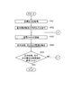
次に、図12A~図12Dに示すフローチャートを参照して、本実施形態に係る非接触給電装置10の一動作例について説明する。
ステップS101において、駆動周波数検索回路27は、バッテリ33を充電する際に要求される目標出力Ptを取得する。
ステップS102において、駆動周波数検索回路27は、インバータ23に基本周波数f0及び目標出力Ptを送信する。
ステップS103において、インバータ23は、基本周波数f0を用い、目標出力Ptに対応した出力で送電コイル11を励磁する。
ステップS104において、駆動周波数検索回路27は、インバータ23の出力位相θ及び出力電流Iを検出する。
ステップS105において、駆動周波数検索回路27は、インバータ23の出力位相θ及び出力電流Iが、制限値を達成したか否かを判定する。インバータ23の出力位相θ及び出力電流Iが、ともに制限値を達成した場合(ステップS105でYes)、駆動周波数検索回路27は、駆動周波数fの検索を終了する。一方、インバータ23の出力位相θ及び出力電流Iの少なくとも一方が、制限値を達成しない場合(ステップS105でNo)、処理はステップS201に進む。
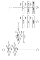
図12Bに示すステップS201において、駆動周波数検索回路27は、駆動周波数fが上限周波数f4か否かを判定する。駆動周波数fが上限周波数f4である場合(ステップS201でYes)、処理はステップS208に進む。一方、駆動周波数fが上限周波数f4でない場合(ステップS201でNo)、処理はステップS202に進む。
ステップS202において、駆動周波数検索回路27は、駆動周波数fが基本周波数f0か否かを判定する。駆動周波数fが基本周波数f0である場合(ステップS202でYes)、処理はステップS203に進む。一方、駆動周波数fが基本周波数f0でない場合(ステップS202でNo)、処理はステップS301に進む。
ステップS203において、駆動周波数検索回路27は、出力位相θが制限値を達成したか否かを判定する。出力位相θが制限値を達成した場合(ステップS203でYes)、処理がステップS204に進む。一方、出力位相θが制限値を達成しない場合(ステップS203でNo)、処理はステップS205に進む。
ステップS204において、駆動周波数検索回路27は、駆動周波数fから所定量fsを減算し、変更後の駆動周波数fuを計算する。
ステップS205において、駆動周波数検索回路27は、駆動周波数fに所定量fsを加算し、変更後の駆動周波数fuを計算する。
ステップS206において、駆動周波数検索回路27は、駆動周波数fを変更前の駆動周波数fpとして計算する。
ステップS207において、駆動周波数検索回路27は、変更後の駆動周波数fuをインバータ23に送信する。
ステップS208において、駆動周波数検索回路27は、変更後の駆動周波数fuを上限周波数f4として計算する。
ステップS209において、電力制御回路28は、目標出力Ptを下げる。
ステップS210において、駆動周波数検索回路27は、変更後の駆動周波数fu及びステップS209の処理によって下げられた目標出力Ptをインバータ23に送信する。
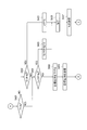
図12Cに示すステップS301において、駆動周波数検索回路27は、出力位相θが制限値を達成したか否かを判定する。出力位相θが制限値を達成した場合(ステップS301でYes)、処理がステップS302に進む。一方、出力位相θが制限値を達成しない場合(ステップS301でNo)、処理はステップS401に進む。
ステップS302において、駆動周波数検索回路27は、駆動周波数fが変更前の駆動周波数fpより小さいか否かをする。駆動周波数fが変更前の駆動周波数fpより小さい場合(ステップS302でYes)、処理はステップS303に進む。一方、駆動周波数fが変更前の駆動周波数fpより大きい場合(ステップS302でNo)、処理はステップS307に進む。
ステップS303において、駆動周波数検索回路27は、所定量fsが、駆動周波数fから変更前の駆動周波数fpを減算した値の絶対値と同じか否かを判定する。所定量fsが、駆動周波数fから変更前の駆動周波数fpを減算した値の絶対値と同じ場合(ステップS303でYes)、処理はステップS304に進む。一方、所定量fsが、駆動周波数fから変更前の駆動周波数fpを減算した値の絶対値と異なる場合(ステップS303でNo)、処理はステップS307に進む。
ステップS304において、駆動周波数検索回路27は、駆動周波数fから所定量fsを減算し、変更後の駆動周波数fuを計算する。
ステップS305において、駆動周波数検索回路27は、変更後の駆動周波数fuが下限周波数f1より小さいか否かを判定する。変更後の駆動周波数fuが下限周波数f1より小さい場合(ステップS305でYes)、処理はステップS306に進む。一方、変更後の駆動周波数fuが下限周波数f1以上の場合(ステップS305でNo)、処理はステップS309に進む。
ステップS306において、駆動周波数検索回路27は、変更後の駆動周波数fuを上限周波数f4として計算する。
ステップS307において、駆動周波数検索回路27は、駆動周波数fから変更前の駆動周波数fpを減算した値の絶対値が、最小量fm以上か否かを判定する。駆動周波数fから変更前の駆動周波数fpを減算した値の絶対値が、最小量fm以上の場合(ステップS307でYes)、処理はステップS308に進む。一方、駆動周波数fから変更前の駆動周波数fpを減算した値の絶対値が、最小量fmより小さい場合(ステップS307でNo)、処理はステップS311に進む。
ステップS308において、駆動周波数検索回路27は、駆動周波数fから変更前の駆動周波数fpを減算した値の絶対値を半分にする。そして、駆動周波数検索回路27は、駆動周波数fから半分にした値を減算し、変更後の駆動周波数fuを計算する。
ステップS309において、駆動周波数検索回路27は、駆動周波数fを変更前の駆動周波数fpとして計算する。
ステップS310において、駆動周波数検索回路27は、変更後の駆動周波数fuをインバータ23に送信する。
ステップS311において、電力制御回路28は、目標出力Ptを下げる。
ステップS312において、駆動周波数検索回路27は、ステップS311の処理によって下げられた目標出力Ptをインバータ23に送信する。
図12Dに示すステップS401において、駆動周波数検索回路27は、駆動周波数fが変更前の駆動周波数fpより小さいか否かをする。駆動周波数fが変更前の駆動周波数fpより小さい場合(ステップS401でYes)、処理はステップS404に進む。一方、駆動周波数fが変更前の駆動周波数fpより大きい場合(ステップS401でNo)、処理はステップS402に進む。
ステップS402において、駆動周波数検索回路27は、所定量fsが、駆動周波数fから変更前の駆動周波数fpを減算した値の絶対値と同じか否かを判定する。所定量fsが、駆動周波数fから変更前の駆動周波数fpを減算した値の絶対値と同じ場合(ステップS402でYes)、処理はステップS403に進む。一方、所定量fsが、駆動周波数fから変更前の駆動周波数fpを減算した値の絶対値と異なる場合(ステップS402でNo)、処理はステップS404に進む。
ステップS403において、駆動周波数検索回路27は、駆動周波数fに所定量fsを加算し、変更後の駆動周波数fuを計算する。
ステップS404において、駆動周波数検索回路27は、駆動周波数fから変更前の駆動周波数fpを減算した値の絶対値が、最小量fm以上か否かを判定する。駆動周波数fから変更前の駆動周波数fpを減算した値の絶対値が、最小量fm以上の場合(ステップS404でYes)、処理はステップS405に進む。一方、駆動周波数fから変更前の駆動周波数fpを減算した値の絶対値が、最小量fmより小さい場合(ステップS404でNo)、処理はステップS408に進む。
ステップS405において、駆動周波数検索回路27は、駆動周波数fから変更前の駆動周波数fpを減算した値の絶対値を半分にする。そして、駆動周波数検索回路27は、駆動周波数fに半分にした値を加算し、変更後の駆動周波数fuを計算する。
ステップS406において、駆動周波数検索回路27は、駆動周波数fを変更前の駆動周波数fpとして計算する。
ステップS407において、駆動周波数検索回路27は、変更後の駆動周波数fuをインバータ23に送信する。
ステップS408において、電力制御回路28は、目標出力Ptを下げる。
ステップS409において、駆動周波数検索回路27は、ステップS408の処理によって下げられた目標出力Ptをインバータ23に送信する。
以上説明したように、本実施形態に係る非接触給電方法によれば、以下の作用効果が得られる。
駆動周波数検索回路27は、バッテリ33を充電する前に目標出力Ptを取得し、インバータ23を基本周波数f0で駆動させ目標出力Ptを出力させる。このとき、駆動周波数検索回路27は、インバータ23の出力位相θを検出し、インバータ23の出力位相θが制限値を達成したか否かを判定する。インバータ23の出力位相θが制限値を達成しない場合、駆動周波数検索回路27は、駆動周波数fを所定量fs、基本周波数f0から高周波数側に変更し、インバータ23の出力位相θが制限値を達成する駆動周波数fを検索する。これにより、駆動周波数検索回路27は、基本周波数f0から高周波数側を探索して駆動周波数fを検出できるため、無作為に全駆動周波数を検索する場合と比べて、検出にかかる時間を短縮できる確率が高まる。
また、駆動周波数検索回路27は、インバータ23の出力位相θが制限値を達成した場合に、インバータ23の出力電流Iが制限値を達成したか否かを判定する。インバータ23の出力電流Iが制限値を達成しない場合、駆動周波数検索回路27は、駆動周波数fを所定量fs、低周波数側に変更し、インバータ23の出力電流Iが制限値を達成する駆動周波数fを検索する。これにより、駆動周波数検索回路27は、低周波数側を探索して駆動周波数fを検出できるため、無作為に全駆動周波数を検索する場合と比べて、検出にかかる時間を短縮できる確率が高まる。
また、本実施形態に係る非接触給電方法では、上限周波数f4及び下限周波数f1が設定されており、駆動周波数fが下限周波数f1より低くなる場合、駆動周波数検索回路27は、駆動周波数fを上限周波数f4に変更する。これにより、駆動周波数fの検索にかかる時間を短縮できる確率が高まり、検索範囲の漏れがなくなる。
また、駆動周波数fが上限周波数f4より高くなる場合、駆動周波数検索回路27は、駆動周波数fの検索を終了し、電力制御回路28は、目標出力Ptを下げる。これにより、充電ができなくなる事態は回避される。
また、駆動周波数fを変更する向きが高周波数側から低周波数側に、または低周波数側から高周波数側に変わった場合、駆動周波数検索回路27は、所定量fsを小さくして駆動周波数fを変更する。駆動周波数fを変更する向きが変わる場合、その駆動周波数fの近くにインバータ23の駆動条件を満たす駆動周波数fが存在する可能性がある。そこで、駆動周波数検索回路27は、所定量fsを小さくして駆動周波数fを検索する。これにより、インバータ23の駆動条件を満たす駆動周波数fを検索できる確率が高まる。
また、所定量fsが最小量fmより小さくなった場合、駆動周波数検索回路27は、駆動周波数fの検索を終了し、電力制御回路28は、目標出力Ptを下げる。これにより、充電ができなくなる事態は回避される。
上記のように、本発明の実施形態を記載したが、この開示の一部をなす論述及び図面はこの発明を限定するものであると理解すべきではない。この開示から当業者には様々な代替実施の形態、実施例及び運用技術が明らかとなろう。
本実施形態の駆動周波数検索回路27は、インバータ23の出力位相θが制限値を達成した後に、インバータ23の出力電流Iが制限値を達成したか否かを判定したが、これに限定されない。例えば、駆動周波数検索回路27は、出力位相θが制限値を達成した後に、出力電流Iの代わりに、インバータ23の出力電力または出力電圧Vが制限値を達成したか否かを判定してもよい。また、駆動周波数検索回路27は、出力位相θが制限値を達成した後に、出力電流Iに加えて出力電力または出力電圧Vが制限値を達成したか否かを判定してもよい。また、駆動周波数検索回路27は、出力位相θが制限値を達成した後に、出力電流I、出力電力、及び出力電圧Vが制限値を達成したか否かを判定してもよい。なお、出力電力または出力電圧Vが制限値を達成していない場合、駆動周波数検索回路27は、出力電流Iと同様に駆動周波数fを所定量fs、低周波数側に変更すればよい。
また、駆動周波数検索回路27は、目標出力Ptを段階的に増加させながらインバータ23に送信するようにしてもよい。これにより、駆動周波数検索回路27は、インバータ23をより安全に駆動させることができる。
また、駆動周波数検索回路27は、所定量fsを段階的に小さくする際に半分にしながら小さくしたが、これに限定されない。例えば、駆動周波数検索回路27は、所定量fsを三分の一にしながら小さくしてもよく、所定値減少させながら小さくしてもよい。
また、本実施形態において、最小量fmは、0.0625kHzとして説明したが、これに限定されず、最小量fmは適宜変更できる。
なお、上述の実施形態の各機能は、1または複数の処理回路により実装され得る。処理回路は、電気回路を含む処理装置等のプログラムされた処理装置を含む。処理回路は、また、実施形態に記載された機能を実行するようにアレンジされた特定用途向け集積回路(ASIC)や従来型の回路部品のような装置を含む。
10 非接触給電装置
11 送電コイル
12 ケーブル
20 コントローラ
21 整流器
22 PFC回路
23 インバータ
24 電圧センサ
25 電流センサ
26 位相差センサ
27 駆動周波数検索回路
28 電力制御回路
30 車両
31 受電コイル
32 整流器
33 バッテリ
34 電力センサ
100 交流電源
11 送電コイル
12 ケーブル
20 コントローラ
21 整流器
22 PFC回路
23 インバータ
24 電圧センサ
25 電流センサ
26 位相差センサ
27 駆動周波数検索回路
28 電力制御回路
30 車両
31 受電コイル
32 整流器
33 バッテリ
34 電力センサ
100 交流電源
Claims (7)
- 車両用コイルに給電する送電コイルと、前記送電コイルを励磁するインバータと、を備える非接触給電装置の非接触給電方法であって、
前記車両用コイルに給電する前に、前記インバータの目標出力を取得し、
前記目標出力に対応する出力で前記送電コイルを励磁した際の前記インバータの出力位相を検出し、
前記出力位相が第1所定値より小さい場合、前記インバータの駆動周波数を所定量、基本周波数から高周波数側に変更することを特徴とする非接触給電方法。 - 前記目標出力に対応する出力で前記送電コイルを励磁した際の前記インバータの出力電力または出力電流を検出し、
前記出力電力または出力電流が第2所定値より大きい場合、前記駆動周波数を前記所定量、低周波数側に変更することを特徴とする請求項1に記載の非接触給電方法。 - 上限周波数、及び下限周波数を設定し、
前記駆動周波数が前記下限周波数より低い場合、前記駆動周波数を前記上限周波数に変更することを特徴とする請求項2に記載の非接触給電方法。 - 前記駆動周波数が前記上限周波数より高い場合、前記目標出力を下げることを特徴とする請求項3に記載の非接触給電方法。
- 前記駆動周波数を変更する向きが前記高周波数側から低周波数側に変わった場合、または、前記低周波数側から前記高周波数側に変わった場合、前記所定量を小さくすることを特徴とする請求項2~4のいずれか1項に記載の非接触給電方法。
- 前記所定量が最小量より小さくなった場合、前記目標出力を下げることを特徴とする請求項5に記載の非接触給電方法。
- 車両用コイルに給電する送電コイルと、
前記送電コイルを励磁するインバータと、
前記インバータを制御するコントローラと、を備え、
前記コントローラは、前記車両用コイルに給電する前に、前記インバータの目標出力を取得し、取得した前記目標出力で前記送電コイルを励磁した際の前記インバータの出力位相を検出し、検出した前記出力位相が所定値より小さい場合、前記インバータの駆動周波数を所定量、高周波数側に変更することを特徴とする非接触給電装置。
Priority Applications (1)
| Application Number | Priority Date | Filing Date | Title |
|---|---|---|---|
| PCT/JP2016/064614 WO2017199337A1 (ja) | 2016-05-17 | 2016-05-17 | 非接触給電方法及び非接触給電装置 |
Applications Claiming Priority (1)
| Application Number | Priority Date | Filing Date | Title |
|---|---|---|---|
| PCT/JP2016/064614 WO2017199337A1 (ja) | 2016-05-17 | 2016-05-17 | 非接触給電方法及び非接触給電装置 |
Publications (1)
| Publication Number | Publication Date |
|---|---|
| WO2017199337A1 true WO2017199337A1 (ja) | 2017-11-23 |
Family
ID=60324979
Family Applications (1)
| Application Number | Title | Priority Date | Filing Date |
|---|---|---|---|
| PCT/JP2016/064614 Ceased WO2017199337A1 (ja) | 2016-05-17 | 2016-05-17 | 非接触給電方法及び非接触給電装置 |
Country Status (1)
| Country | Link |
|---|---|
| WO (1) | WO2017199337A1 (ja) |
Citations (2)
| Publication number | Priority date | Publication date | Assignee | Title |
|---|---|---|---|---|
| JP2012191764A (ja) * | 2011-03-10 | 2012-10-04 | Hitachi Maxell Energy Ltd | 充電システム及び該充電システムを用いた充電方法 |
| JP2015216739A (ja) * | 2014-05-09 | 2015-12-03 | 三菱電機株式会社 | 送電装置 |
-
2016
- 2016-05-17 WO PCT/JP2016/064614 patent/WO2017199337A1/ja not_active Ceased
Patent Citations (2)
| Publication number | Priority date | Publication date | Assignee | Title |
|---|---|---|---|---|
| JP2012191764A (ja) * | 2011-03-10 | 2012-10-04 | Hitachi Maxell Energy Ltd | 充電システム及び該充電システムを用いた充電方法 |
| JP2015216739A (ja) * | 2014-05-09 | 2015-12-03 | 三菱電機株式会社 | 送電装置 |
Similar Documents
| Publication | Publication Date | Title |
|---|---|---|
| JP5126324B2 (ja) | 給電装置、および給電システムの制御方法 | |
| EP2405556B1 (en) | Non-contact power supplying device and non-contact power supplying method | |
| JP6299738B2 (ja) | 非接触送電装置及び電力伝送システム | |
| CN102870315B (zh) | 电力接收装置以及电力接收方法 | |
| JP5285418B2 (ja) | 共鳴型非接触電力供給装置 | |
| JP6036995B2 (ja) | 非接触給電システム | |
| US8421411B2 (en) | Resonance type non-contact charging device | |
| CN105814772A (zh) | 混合式无线电力传输系统及其方法 | |
| WO2012164744A1 (ja) | 非接触受電装置およびそれを備える車両、非接触送電装置、ならびに非接触電力伝送システム | |
| JP5843066B2 (ja) | 電力伝送システムおよび送電装置 | |
| JP2013017254A (ja) | 電力伝送システム | |
| JP2012257395A (ja) | 非接触受電装置およびそれを備える車両、非接触送電装置、ならびに非接触電力伝送システム | |
| KR102396628B1 (ko) | 무접촉 에너지 전송을 위한 전송 시스템 | |
| WO2012157115A1 (ja) | 受電装置およびそれを備える車両、給電設備、ならびに給電システム | |
| CN106104963A (zh) | 供电装置以及非接触供电系统 | |
| US20190006843A1 (en) | Power transmission device and power reception device | |
| US10355530B2 (en) | Non-contact power supply apparatus, program, method for controlling non-contact power supply apparatus, and non-contact power transmission system | |
| US20140354075A1 (en) | Electric power transmission system and power transmission device | |
| JP6675094B2 (ja) | 非接触給電装置、プログラム、非接触給電装置の制御方法、及び非接触電力伝送システム | |
| JP2015156742A (ja) | 受電装置 | |
| KR101681376B1 (ko) | 전력 공급 장치 | |
| JP6675093B2 (ja) | 非接触給電装置、プログラム、非接触給電装置の制御方法、及び非接触電力伝送システム | |
| JP2012210116A (ja) | 電力伝送システム | |
| JP6678325B2 (ja) | 非接触給電装置、非接触電力伝送システム、プログラムおよび非接触給電装置の制御方法 | |
| KR20150026874A (ko) | 전원 공급 장치 |
Legal Events
| Date | Code | Title | Description |
|---|---|---|---|
| NENP | Non-entry into the national phase |
Ref country code: DE |
|
| 121 | Ep: the epo has been informed by wipo that ep was designated in this application |
Ref document number: 16902357 Country of ref document: EP Kind code of ref document: A1 |
|
| 122 | Ep: pct application non-entry in european phase |
Ref document number: 16902357 Country of ref document: EP Kind code of ref document: A1 |
|
| NENP | Non-entry into the national phase |
Ref country code: JP |