WO2017195795A1 - 構造体及びその製造方法 - Google Patents
構造体及びその製造方法 Download PDFInfo
- Publication number
- WO2017195795A1 WO2017195795A1 PCT/JP2017/017598 JP2017017598W WO2017195795A1 WO 2017195795 A1 WO2017195795 A1 WO 2017195795A1 JP 2017017598 W JP2017017598 W JP 2017017598W WO 2017195795 A1 WO2017195795 A1 WO 2017195795A1
- Authority
- WO
- WIPO (PCT)
- Prior art keywords
- vertical wall
- wall portion
- molding material
- flange
- die
- Prior art date
- Legal status (The legal status is an assumption and is not a legal conclusion. Google has not performed a legal analysis and makes no representation as to the accuracy of the status listed.)
- Ceased
Links
Images


Classifications
-
- B—PERFORMING OPERATIONS; TRANSPORTING
- B21—MECHANICAL METAL-WORKING WITHOUT ESSENTIALLY REMOVING MATERIAL; PUNCHING METAL
- B21D—WORKING OR PROCESSING OF SHEET METAL OR METAL TUBES, RODS OR PROFILES WITHOUT ESSENTIALLY REMOVING MATERIAL; PUNCHING METAL
- B21D22/00—Shaping without cutting, by stamping, spinning, or deep-drawing
- B21D22/20—Deep-drawing
- B21D22/26—Deep-drawing for making peculiarly, e.g. irregularly, shaped articles
-
- B—PERFORMING OPERATIONS; TRANSPORTING
- B62—LAND VEHICLES FOR TRAVELLING OTHERWISE THAN ON RAILS
- B62D—MOTOR VEHICLES; TRAILERS
- B62D25/00—Superstructure or monocoque structure sub-units; Parts or details thereof not otherwise provided for
- B62D25/20—Floors or bottom sub-units
- B62D25/2009—Floors or bottom sub-units in connection with other superstructure subunits
- B62D25/2036—Floors or bottom sub-units in connection with other superstructure subunits the subunits being side panels, sills or pillars
-
- B—PERFORMING OPERATIONS; TRANSPORTING
- B21—MECHANICAL METAL-WORKING WITHOUT ESSENTIALLY REMOVING MATERIAL; PUNCHING METAL
- B21D—WORKING OR PROCESSING OF SHEET METAL OR METAL TUBES, RODS OR PROFILES WITHOUT ESSENTIALLY REMOVING MATERIAL; PUNCHING METAL
- B21D22/00—Shaping without cutting, by stamping, spinning, or deep-drawing
- B21D22/02—Stamping using rigid devices or tools
-
- B—PERFORMING OPERATIONS; TRANSPORTING
- B21—MECHANICAL METAL-WORKING WITHOUT ESSENTIALLY REMOVING MATERIAL; PUNCHING METAL
- B21D—WORKING OR PROCESSING OF SHEET METAL OR METAL TUBES, RODS OR PROFILES WITHOUT ESSENTIALLY REMOVING MATERIAL; PUNCHING METAL
- B21D24/00—Special deep-drawing arrangements in, or in connection with, presses
-
- B—PERFORMING OPERATIONS; TRANSPORTING
- B21—MECHANICAL METAL-WORKING WITHOUT ESSENTIALLY REMOVING MATERIAL; PUNCHING METAL
- B21D—WORKING OR PROCESSING OF SHEET METAL OR METAL TUBES, RODS OR PROFILES WITHOUT ESSENTIALLY REMOVING MATERIAL; PUNCHING METAL
- B21D35/00—Combined processes according to or processes combined with methods covered by groups B21D1/00 - B21D31/00
- B21D35/002—Processes combined with methods covered by groups B21D1/00 - B21D31/00
- B21D35/005—Processes combined with methods covered by groups B21D1/00 - B21D31/00 characterized by the material of the blank or the workpiece
-
- B—PERFORMING OPERATIONS; TRANSPORTING
- B21—MECHANICAL METAL-WORKING WITHOUT ESSENTIALLY REMOVING MATERIAL; PUNCHING METAL
- B21D—WORKING OR PROCESSING OF SHEET METAL OR METAL TUBES, RODS OR PROFILES WITHOUT ESSENTIALLY REMOVING MATERIAL; PUNCHING METAL
- B21D47/00—Making rigid structural elements or units, e.g. honeycomb structures
- B21D47/01—Making rigid structural elements or units, e.g. honeycomb structures beams or pillars
-
- B—PERFORMING OPERATIONS; TRANSPORTING
- B62—LAND VEHICLES FOR TRAVELLING OTHERWISE THAN ON RAILS
- B62D—MOTOR VEHICLES; TRAILERS
- B62D25/00—Superstructure or monocoque structure sub-units; Parts or details thereof not otherwise provided for
- B62D25/20—Floors or bottom sub-units
-
- B—PERFORMING OPERATIONS; TRANSPORTING
- B21—MECHANICAL METAL-WORKING WITHOUT ESSENTIALLY REMOVING MATERIAL; PUNCHING METAL
- B21D—WORKING OR PROCESSING OF SHEET METAL OR METAL TUBES, RODS OR PROFILES WITHOUT ESSENTIALLY REMOVING MATERIAL; PUNCHING METAL
- B21D53/00—Making other particular articles
- B21D53/88—Making other particular articles other parts for vehicles, e.g. cowlings, mudguards
-
- B—PERFORMING OPERATIONS; TRANSPORTING
- B62—LAND VEHICLES FOR TRAVELLING OTHERWISE THAN ON RAILS
- B62D—MOTOR VEHICLES; TRAILERS
- B62D25/00—Superstructure or monocoque structure sub-units; Parts or details thereof not otherwise provided for
- B62D25/04—Door pillars ; windshield pillars
Definitions
- the present invention relates to a structure suitable for an automobile member and a method for manufacturing the same.
- Patent Document 1 discloses a technique for increasing the thickness against the load input from the front surface by increasing the thickness of the vehicle front side by the reinforcement inside the A pillar lower.
- the thick part due to reinforcement is only the front surface, and no consideration is given to the load entering the side sill.
- the front surface of the A pillar is resistant to a load load.
- the load that enters the side sill increases. Only the side sill joined to the side is subject to significant deformation. Furthermore, weight reduction cannot be expected.
- Patent document 2 devises the structure of the reinforcement inside the A pillar to change the traveling direction of the front wheel in the shape of the A pillar lower when the front wheel moves in the event of a collision, thereby suppressing the front wheel from entering the cabin.
- the technology is disclosed.
- Patent Document 2 The technology of Patent Document 2 is effective only when the front wheels are directed in the traveling direction and the width of the front wheels is not too large in the vehicle width direction of the A pillar lower.
- the front wheel is directed obliquely or when the front wheel width is wide, it is necessary to receive a load on a wide surface, and thus an effect cannot be expected.
- a dash cross may be connected to the A pillar lower inner.
- the dash cloth is joined to the A pillar lower inner by raising the flange. For this reason, there is a problem that when the dash cross is displaced, the joint is easily peeled off.
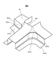
- a structure having an integrally formed A pillar, a joint in the dash cross direction, a joint in the side sill direction, and a three-dimensional three-pronged shape capable of transmitting a load can be used as the A pillar lower inner.
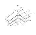
- a structure comprising a vertical wall portion (15) bent downward from an outer edge portion (14) including a portion (13) and extending along the outer edge portion, and a substantially L-shaped lower flange portion (16) extending outward from the vertical wall portion.
- Such a structure can be produced by stretch flange molding and a free bending method, and the protruding portion (12) can be formed by stretch flange molding, and the vertical wall portion (15) and the lower flange portion (16) can be molded by free bending method. it can.
- Patent Document 3 The free bending method is disclosed in Patent Document 3, for example.
- the invention described in Patent Document 3 is a blank (molding material) such as an L-shaped member that has a substantially hat-shaped cross section and has a bent portion in which the vertical wall portion protrudes toward the top plate in plan view. It is the method of shape
- the blank is disposed between the die mold, the pad, and the bending mold, and (1) a part of the portion corresponding to the top plate portion of the blank as an out-of-plane deformation suppression region is pressed by the pad.
- the die mold and the bending die are moved relative to each other in the vertical direction.
- the pad is brought close to or in contact with a part of the blank corresponding to the top plate portion as the out-of-plane deformation suppressing region, and the gap between the pad and the die mold is not less than the blank plate thickness.
- the die mold and the bending mold are vertically placed in a state where the thickness is maintained at 1.1 times or less and the end of the portion corresponding to the lower side of the L-shape of the blank is on the same plane as the top plate portion.
- the end of the portion corresponding to the lower side of the L-shape of the blank is slid (moved in the plane) on the portion corresponding to the top plate portion of the die die.
- An L-shaped part or the like is formed by forming the wall portion and the flange portion.
- the forming method using stretch flange forming and the free bending method is an excellent method for producing a structure having a three-dimensional trifurcated shape.
- a shape with more severe formability may be required, for example, when the radius of curvature of the boundary between the vertical wall portion and the lower flange portion is small, or the upper arm is enlarged in cross-sectional shape or the arm length is extended. In such a case, it is necessary to further improve the moldability.
- the present invention has been made in view of the above circumstances, and an object thereof is to provide a structure having improved formability and a method for manufacturing the structure.
- the present inventors diligently studied a method for improving the moldability of a structure having a three-dimensional trifurcated shape.
- the second vertical wall portion (12) is formed in the first step, and then the first vertical wall portion (15) and the first flange portion (16) are formed in the second step.
- the following knowledge was obtained. Specifically, when the second vertical wall portion (12) is manufactured, a blank portion that is to become the first flange portion (16) in the second step, preferably the first flange portion (16) and the first flange portion (12).
- the step of forming the second vertical wall portion by pressurizing and deforming the molding raw material and the molding material on which the second vertical wall portion is formed are disposed between the die and the blank holder.
- the die or blank holder is provided with a space in at least a part of a position in contact with a molding material at the time of pressurization.
- the molding material having the first vertical wall portion, the first flange portion, and the second vertical wall portion is disposed between a die and a blank holder, and is moved relative to the punch to thereby form the molding material.
- the manufacturing method of the structure according to (5), wherein the forming method includes arranging a molding material, which is a flat plate, between a die and a blank holder and moving the molding material relative to a punch.
- the step of forming the second vertical wall portion and the second flange portion by pressurizing and deforming the raw material, and the molding material on which the second vertical wall portion is formed are disposed between the die and the blank holder.
- the die or blank holder used in the step of forming a part is provided with a space at least at a part of a position in contact with the molding material at the time of pressurization.
- the molding material on which the first vertical wall portion, the first flange portion, and the second vertical wall portion and the second flange portion are formed is disposed between the die and the blank holder, and is moved relative to the punch.
- the present invention it is possible to improve the moldability in the manufacturing method of the structure having a three-dimensional trifurcated shape, which is a shape having a severe moldability.
- the manufacturing method of the structure of the present invention includes a punch, a die, and press forming a blank with a press forming apparatus provided with a pad that presses and restrains a blank (molding material) such as a metal plate against the punch, stretch flange molding, And can be produced by a free bending method.
- a press forming apparatus provided with a pad that presses and restrains a blank (molding material) such as a metal plate against the punch, stretch flange molding, And can be produced by a free bending method.
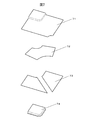
- the second vertical wall portion (12) is formed by stretch flange molding. More specifically, as shown in FIG. 2, the second vertical wall portion (12) is formed on the blank (21) using a punch (22) and a die (23).
- the blank holder (24) holds the blank (21) together with the die (23), adjusts the material flow, and prevents wrinkles.
- the blank holder (24) does not necessarily need to be in close contact with the blank (21), and there may be a gap.
- the blank holder (24) does not completely cover the blank (21), and a space (25) for allowing the material to flow in is provided.
- the blank (21) is sandwiched between the die (23) and the blank holder (24). Subsequently, the punch (22) and the die (23) are relatively moved, and the blank (21) is pressurized to form the second vertical wall portion (12). At this time, the punch (22) at a position corresponding to the space (25) of the blank holder (24) is also shaped so as not to hinder the deformation of the blank (21).
- the second vertical wall portion is formed such that a concave bend line is formed on the blank (21), and this bend line becomes the outer peripheral portion of the top plate portion.
- Tensile strain centered on the strain in the tangential direction of the upper end of the second vertical wall (the portion that was the outer edge of the blank (21)) is concentrated at the center of the upper end of the second vertical wall.
- a compressive stress is generated in the minimum principal strain direction (generally in the normal direction at the center of the upper end of the second vertical wall).
- the center of the upper end portion does not mean a substantial center, but the upper end of the second vertical wall portion close to the R portion of the first vertical wall portion (15) or the first flange portion to be formed later. Part.
- the blank (21) is not restrained in the thickness direction in the space (25) portion of the blank holder (24), and the blank (21) is deformed out of plane. can do.
- free buckling such free out-of-plane deformation is referred to as “free buckling”.
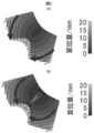
- FIG. 3 shows the movement of the material when forming the second vertical wall portion in the blank.
- (A) shows a case where no space is formed in the blank holder, and
- (b) shows a space in the blank holder. It is an example in the case of being formed.
- (b) of the present invention it is understood that the material inflow amount to the upper end portion of the second vertical wall portion is increased by providing a space in the blank holder.
- the position where the protrusion is generated is preferably a portion where the first flange portion (16) is formed in the second step described later, and the first flange portion (16) and the first flange portion are formed. It is more preferable that it becomes a part where the boundary of the vertical wall portion (15) is formed. The reason is that when the first flange portion is formed by a free bending method, the plate thickness near the boundary between the first flange portion and the first vertical wall portion is most likely to decrease.
- the shape and size of the space (25) are not particularly limited, and the effect of the present invention can be obtained as long as the material flows in and is provided in a portion intended to increase the thickness.
- the slit shape having a width of about 60 to 200 mm is used. Good.
- the first vertical wall portion (15) and the first flange portion (16) are formed. More specifically, as shown in FIG. 4, a flange is formed on a blank (31) using a punch (32) and a die (34). The pad (33) presses and holds the blank (31) against the punch (32). By pushing the blank (31) fixed by the die (34), the first vertical wall portion (15) and the first flange portion (16) along the outer edge portion are simultaneously formed in the blank.
- the portion that becomes the first flange portion (16) in the second step preferably the first flange portion (16) and the first vertical wall portion (15). Since the protrusion is formed at the portion that becomes the boundary, the reduction in the plate thickness at the portion where the reduction in the plate thickness is likely to occur by the free bending method is reduced.
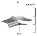
- FIG. 5 is a diagram showing an example of the plate thickness reduction rate of the structure manufactured by the manufacturing method of the present invention.
- FIG. 6 shows the thickness reduction rate of a structure manufactured by a manufacturing method in which free buckling does not occur.
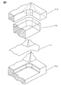
- FIG. 7 shows an outline in the case of forming the second vertical wall portion and the second flange portion in the first step.
- the shapes of the die (71) and the punch (74) are different.
- the second vertical wall portion is combined with the second vertical wall portion.
- a second flange portion that bends and extends from the wall portion is formed.
- the molding material on which the first vertical wall portion (15), the first flange portion (16), and the second vertical wall portion (12) are formed is placed between the die and the blank holder.
- a wrist-like process for adjusting the shape of the second vertical wall portion (12) may be provided by arranging and relatively moving with the punch.
- a special apparatus is used for processing a structure having a three-dimensional triangulated shape, which is a shape having a severe formability, by performing processing using a general press machine. It can be manufactured in a short working time without using it. In particular, it is effective for manufacturing a structure using a high-strength steel plate, which is likely to be cracked during processing.
- the flange is trifurcated, but it is also possible to form a four-pronged flange in the same manner.
- the four-pronged flange has a substantially T-shaped top plate portion, a vertical wall portion and a flange provided along two outer edge portions that are substantially L-shaped, and in the vicinity of the T-shaped intersection of the top plate portion. It can be set as the shape which has the protrusion part which is an elongate flange.
- Fig. 8 shows an example of a four-pronged flange.
- the top plate portion 81 including two concave portions 82a and 82b at the outer edge portion in plan view, the first vertical wall portions 83a and 83b extending from the concave portions 82a and 82b, respectively, First flange portions 84a and 84b that bend and extend from edges opposite to the top plate portion of the wall portions 83a and 83b, and a second vertical wall portion that bends and extends from an edge different from the outer edge portion including the concave portion of the top plate portion.
- the top plate portion 81 including two concave portions 82a and 82b at the outer edge portion in plan view, the first vertical wall portions 83a and 83b extending from the concave portions 82a and 82b, respectively, First flange portions 84a and 84b that bend and extend from edges opposite to the top plate portion of the wall portions 83a and 83b, and a second vertical wall portion that bend
- a high-strength steel plate having a plate thickness of 0.6 to 1.8 mm, preferably 0.6 to 1.2 mm and a tensile strength of 980 MPa or more is suitable. Further, a resin composite material flat plate such as an aluminum alloy plate or FRP can also be used.
- the curvature R when the top plate portion is viewed from above and the height h of the first vertical wall portion are not particularly limited.
- a structure with reduced molding defects can be formed even if the R / h is a shape of 0.6 to 3.0, and the R / h is 0. .8 to 2.7 is more preferable.
- the blank is made of the material shown in the material column.
- the blank having the plate thickness shown in the plate thickness column is sandwiched between the die (23) and the blank holder (24) shown in FIG.
- the punch (22) and the die (23) were moved relative to each other to form a second vertical wall portion.
- the second vertical wall portion was similarly formed using a blank holder (24) having no space (25).
- the blank is pressed against the punch (32) with the pad (33) shown in FIG. 4 and held, and the blank fixed with the die (34) is pressed, so that the first vertical wall portion along the outer edge portion and the first One flange was formed simultaneously.
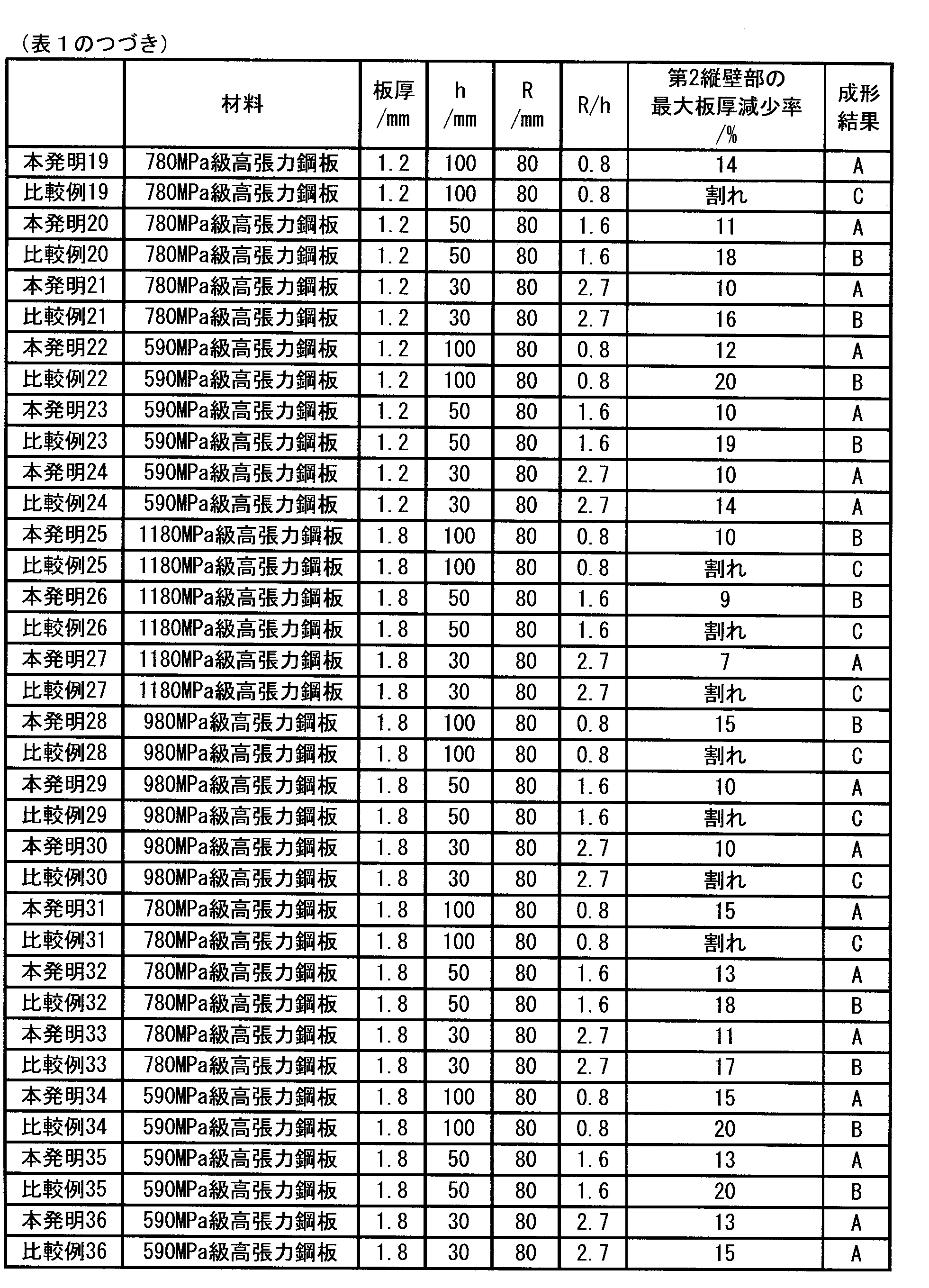
- Table 1 shows the molding results.
- the molding results in the table show that “A” was moldable, “B” was necking occurred in the second vertical wall, and “C” was cracked in the second vertical wall. Means things.
- R in the table indicates the curvature when the top plate portion is viewed from above, and h indicates the height of the first vertical wall portion (see FIG. 1).
- a structure having a trifurcated structure can be formed regardless of the type, thickness and shape of the material.
Landscapes
- Engineering & Computer Science (AREA)
- Mechanical Engineering (AREA)
- Chemical & Material Sciences (AREA)
- Combustion & Propulsion (AREA)
- Transportation (AREA)
- Shaping Metal By Deep-Drawing, Or The Like (AREA)
- Body Structure For Vehicles (AREA)
Abstract
Description

12 第2の縦壁部
13 凹状部
14 外縁部
15 第1の縦壁部
16 第1のフランジ部
21 ブランク
22 パンチ
23 ダイ
24 ブランクホルダー
25 空間
31 ブランク
32 パンチ
33 パッド
34 ダイ
71 ダイ
72 ブランク
73 ブランクホルダー
74 パンチ
81 天板部
82a、82b 凹状部
83a、83b 第1の縦壁部
84a、84b 第1のフランジ部
85 第2の縦壁部
Claims (11)
- 引張強度が590MPa以上の鋼板を用いた一体成形物である構造体であって、
上記構造体は、
平面視において、外縁部に少なくとも1つの凹状部を含む天板部、
上記天板部の上記凹状部を含む外縁部の一部又は全部から折れ曲がり伸びる第1の縦壁部、
上記第1の縦壁部の上記天板部と反対側の縁から折れ曲がり伸びる第1のフランジ部、及び
上記天板部の上記凹状部を含む外縁部と異なる縁から折れ曲がり伸びる第2の縦壁部
を備え、
上記天板部、第1の縦壁部、又は第1のフランジ部上に少なくとも1つの突起部を有する
ことを特徴とする構造体。 - 前記構造体は、引張強度が980MPa以上の鋼板を用いた一体成形物であることを特徴とする請求項1に記載の構造体。
- 前記構造体の板厚が、0.6~1.8mmであることを特徴とする請求項1又は2に記載の構造体。
- 前記凹状部の曲率半径Rと、前記第1の縦壁部の高さhが、0.6≦R/h≦3.0を満たすことを特徴とする請求項1~3のいずれか1項に記載の構造体。
- さらに、前記第2の縦壁部の前記天板部と反対側の縁から折れ曲がり伸びる第2のフランジ部を備えることを特徴とする請求項1~4のいずれか1項に記載の構造体。
- 請求項1~4のいずれか1項に記載の構造体の製造方法であって、
上記製造方法は、
平板である成形素材を、ダイとブランクホルダーの間に配置し、パンチと相対移動させることにより上記成形素材に加圧し変形させることで前記第2の縦壁部を形成する工程、及び
第2の縦壁部が形成された上記成形素材を、ダイとブランクホルダーの間に配置し、パンチと相対移動させることにより上記成形素材に加圧し変形させることで第1の縦壁部及び第1のフランジ部を形成する工程
を備え、
上記第2の縦壁部を形成する工程において用いる上記ダイ又はブランクホルダーは、上記加圧時に成形素材に接する位置の少なくとも一部に空間が設けられている
ことを特徴とする構造体の製造方法。 - 前記空間は、前記第2の縦壁部を形成する際に材料が最も流入する位置を含んで設けられていることを特徴とする請求項6に記載のプレス加工方法。
- 前記第1の縦壁部及び第1のフランジ部並びに第2の縦壁部が形成された成形素材をダイとブランクホルダーの間に配置し、パンチと相対移動させることにより上記成形素材に加圧し変形することで、上記第2の縦壁部の形状を整える工程を備えることを特徴とする請求項6又は7に記載の構造体の製造方法。
- 請求項5に記載の構造体の製造方法であって、
上記製造方法は、
平板である成形素材を、ダイとブランクホルダーの間に配置し、パンチと相対移動させることにより上記成形素材に加圧し変形させることで前記第2の縦壁部及び第2のフランジ部を形成する工程、及び
第2の縦壁部が形成された上記成形素材を、ダイとブランクホルダーの間に配置し、パンチと相対移動させることにより上記成形素材に加圧し変形させることで第1の縦壁部及び第1のフランジ部を形成する工程
を備え、
上記第2の縦壁部及び第2のフランジ部を形成する工程において用いる上記ダイ又はブランクホルダーは、上記加圧時に成形素材に接する位置の少なくとも一部に空間が設けられている
ことを特徴とする構造体の製造方法。 - 前記空間は、前記第2の縦壁部及び第2のフランジ部を形成する際に材料が最も流入する位置を含んで設けられていることを特徴とする請求項9に記載のプレス加工方法。
- 前記第1の縦壁部及び第1のフランジ部並びに第2の縦壁部及び第2のフランジ部が形成された成形素材をダイとブランクホルダーの間に配置し、パンチと相対移動させることにより上記成形素材に加圧し変形することで、上記第2の縦壁部及び第2のフランジ部の形状を整える工程を備えることを特徴とする請求項9又は10に記載の構造体の製造方法。
Priority Applications (5)
| Application Number | Priority Date | Filing Date | Title |
|---|---|---|---|
| JP2018517045A JP6699724B2 (ja) | 2016-05-09 | 2017-05-09 | 構造体の製造方法 |
| US16/097,792 US10858048B2 (en) | 2016-05-09 | 2017-05-09 | Structural member and method of production of same |
| KR1020187027608A KR102131087B1 (ko) | 2016-05-09 | 2017-05-09 | 구조체 및 그 제조 방법 |
| MX2018013318A MX2018013318A (es) | 2016-05-09 | 2017-05-09 | Estructura y metodo de produccion de la misma. |
| CN201780015434.0A CN108778549B (zh) | 2016-05-09 | 2017-05-09 | 构造体及其制造方法 |
Applications Claiming Priority (2)
| Application Number | Priority Date | Filing Date | Title |
|---|---|---|---|
| JP2016-093992 | 2016-05-09 | ||
| JP2016093992 | 2016-05-09 |
Publications (1)
| Publication Number | Publication Date |
|---|---|
| WO2017195795A1 true WO2017195795A1 (ja) | 2017-11-16 |
Family
ID=60267982
Family Applications (1)
| Application Number | Title | Priority Date | Filing Date |
|---|---|---|---|
| PCT/JP2017/017598 Ceased WO2017195795A1 (ja) | 2016-05-09 | 2017-05-09 | 構造体及びその製造方法 |
Country Status (6)
| Country | Link |
|---|---|
| US (1) | US10858048B2 (ja) |
| JP (2) | JP6699724B2 (ja) |
| KR (1) | KR102131087B1 (ja) |
| CN (1) | CN108778549B (ja) |
| MX (1) | MX2018013318A (ja) |
| WO (1) | WO2017195795A1 (ja) |
Cited By (1)
| Publication number | Priority date | Publication date | Assignee | Title |
|---|---|---|---|---|
| WO2021145310A1 (ja) | 2020-01-14 | 2021-07-22 | 日本製鉄株式会社 | 鋼板及びその製造方法 |
Families Citing this family (1)
| Publication number | Priority date | Publication date | Assignee | Title |
|---|---|---|---|---|
| WO2024006051A1 (en) | 2022-06-30 | 2024-01-04 | Cleveland-Cliffs Steel Properties Inc. | Method for prevention of premature edge fracture at draw bead |
Citations (3)
| Publication number | Priority date | Publication date | Assignee | Title |
|---|---|---|---|---|
| JPH10278841A (ja) * | 1997-04-11 | 1998-10-20 | Nissan Motor Co Ltd | 車体上部側面構造 |
| JP2010162973A (ja) * | 2009-01-14 | 2010-07-29 | Toyota Motor Corp | ピラー上部結合構造 |
| JP2010235014A (ja) * | 2009-03-31 | 2010-10-21 | Mazda Motor Corp | 自動車車体におけるチューブ状フレームの連結構造及びその組立方法 |
Family Cites Families (8)
| Publication number | Priority date | Publication date | Assignee | Title |
|---|---|---|---|---|
| US8516874B2 (en) * | 2007-12-27 | 2013-08-27 | Toyota Motor Engineering & Manufacturing North America, Inc. | Pillar for motor vehicle and tool for making the same |
| JP2011037291A (ja) | 2009-08-06 | 2011-02-24 | Toyota Motor Corp | フロントピラー構造 |
| KR101472645B1 (ko) | 2010-05-19 | 2014-12-15 | 신닛테츠스미킨 카부시키카이샤 | L자 형상을 갖는 부품의 프레스 성형 방법 |
| CN103237611B (zh) * | 2010-11-24 | 2015-06-24 | 新日铁住金株式会社 | L形产品的制造方法 |
| US20140191539A1 (en) * | 2011-05-26 | 2014-07-10 | Toyota Jidosha Kabushiki Kaisha | Method of forming header extension, and vehicle structure |
| JP5862214B2 (ja) * | 2011-11-10 | 2016-02-16 | スズキ株式会社 | 車両用シートの取付構造 |
| JP5765246B2 (ja) | 2012-01-11 | 2015-08-19 | トヨタ自動車株式会社 | 車両用フロントピラー構造 |
| CN203604975U (zh) * | 2013-11-15 | 2014-05-21 | 上汽通用五菱汽车股份有限公司 | 一种钣金件及用于加工该钣金件的冲压模具 |
-
2017
- 2017-05-09 US US16/097,792 patent/US10858048B2/en active Active
- 2017-05-09 WO PCT/JP2017/017598 patent/WO2017195795A1/ja not_active Ceased
- 2017-05-09 MX MX2018013318A patent/MX2018013318A/es unknown
- 2017-05-09 JP JP2018517045A patent/JP6699724B2/ja active Active
- 2017-05-09 CN CN201780015434.0A patent/CN108778549B/zh active Active
- 2017-05-09 KR KR1020187027608A patent/KR102131087B1/ko active Active
-
2020
- 2020-01-29 JP JP2020013047A patent/JP6915709B2/ja active Active
Patent Citations (3)
| Publication number | Priority date | Publication date | Assignee | Title |
|---|---|---|---|---|
| JPH10278841A (ja) * | 1997-04-11 | 1998-10-20 | Nissan Motor Co Ltd | 車体上部側面構造 |
| JP2010162973A (ja) * | 2009-01-14 | 2010-07-29 | Toyota Motor Corp | ピラー上部結合構造 |
| JP2010235014A (ja) * | 2009-03-31 | 2010-10-21 | Mazda Motor Corp | 自動車車体におけるチューブ状フレームの連結構造及びその組立方法 |
Cited By (3)
| Publication number | Priority date | Publication date | Assignee | Title |
|---|---|---|---|---|
| WO2021145310A1 (ja) | 2020-01-14 | 2021-07-22 | 日本製鉄株式会社 | 鋼板及びその製造方法 |
| KR20220110828A (ko) | 2020-01-14 | 2022-08-09 | 닛폰세이테츠 가부시키가이샤 | 강판 및 그 제조 방법 |
| US12344912B2 (en) | 2020-01-14 | 2025-07-01 | Nippon Steel Corporation | Steel sheet and manufacturing method thereof |
Also Published As
| Publication number | Publication date |
|---|---|
| JP6699724B2 (ja) | 2020-05-27 |
| US20190168822A1 (en) | 2019-06-06 |
| US10858048B2 (en) | 2020-12-08 |
| KR102131087B1 (ko) | 2020-07-07 |
| JPWO2017195795A1 (ja) | 2019-01-17 |
| MX2018013318A (es) | 2019-03-01 |
| CN108778549B (zh) | 2021-02-26 |
| JP6915709B2 (ja) | 2021-08-04 |
| CN108778549A (zh) | 2018-11-09 |
| KR20180117146A (ko) | 2018-10-26 |
| JP2020090282A (ja) | 2020-06-11 |
Similar Documents
| Publication | Publication Date | Title |
|---|---|---|
| CA2788845C (en) | Press-forming method of component with l shape | |
| CN104870118A (zh) | 冲压部件、其制造方法以及制造装置 | |
| KR20170080681A (ko) | 프레스 성형품의 제조 방법 및 제조 장치 | |
| KR20180021228A (ko) | 블랭크, 성형판, 프레스 성형품의 제조 방법 및 프레스 성형품 | |
| CN115397577B (zh) | 冲压成形方法以及冲压成形件 | |
| KR20200106974A (ko) | 프레스 부품의 제조 방법, 프레스 성형 장치 및 프레스 성형용의 금속판 | |
| WO2017175730A1 (ja) | プレス成形品の製造方法及び製造ライン | |
| KR20220134017A (ko) | 프레스 부품의 제조 방법, 프레스 성형용의 금속판, 및 고장력 강판 | |
| CN107921504B (zh) | 拉伸凸缘成形零件的制造方法 | |
| KR102450454B1 (ko) | 프레스 성형 방법 | |
| KR102196701B1 (ko) | 자동차 구조 부재용 드로잉 성형체, 자동차 구조 부재용 드로잉 성형체의 제조 방법, 및 자동차 구조 부재용 드로잉 성형체의 제조 장치 | |
| JP6733772B1 (ja) | プレス成形方法 | |
| JP6915709B2 (ja) | 構造体 | |
| JP6729841B1 (ja) | プレス成形方法およびプレス装置 | |
| JP2023177203A (ja) | プレス成形方法及びプレス成形品の製造方法 | |
| JP6319382B2 (ja) | 伸びフランジ成形部品の製造方法 | |
| JP7364905B2 (ja) | 板金成形品の製造方法、板金成形品の製造装置、及びフランジアップ工具 | |
| KR102862573B1 (ko) | 프레스 성형 방법 | |
| JP7364904B2 (ja) | 板金成形品製造方法、板金成形品の製造装置及びフランジアップ用工具 | |
| JP2024006554A (ja) | プレス成形品の製造方法 | |
| JP2024001837A (ja) | プレス成形方法及びプレス成形品の製造方法 | |
| JP2017202523A (ja) | 伸びフランジを有する成形体及びその製造方法 |
Legal Events
| Date | Code | Title | Description |
|---|---|---|---|
| WWE | Wipo information: entry into national phase |
Ref document number: 2018517045 Country of ref document: JP |
|
| ENP | Entry into the national phase |
Ref document number: 20187027608 Country of ref document: KR Kind code of ref document: A |
|
| NENP | Non-entry into the national phase |
Ref country code: DE |
|
| 121 | Ep: the epo has been informed by wipo that ep was designated in this application |
Ref document number: 17796156 Country of ref document: EP Kind code of ref document: A1 |
|
| 122 | Ep: pct application non-entry in european phase |
Ref document number: 17796156 Country of ref document: EP Kind code of ref document: A1 |