WO2017195552A1 - 摺動式等速自在継手及びその製造方法 - Google Patents
摺動式等速自在継手及びその製造方法 Download PDFInfo
- Publication number
- WO2017195552A1 WO2017195552A1 PCT/JP2017/015743 JP2017015743W WO2017195552A1 WO 2017195552 A1 WO2017195552 A1 WO 2017195552A1 JP 2017015743 W JP2017015743 W JP 2017015743W WO 2017195552 A1 WO2017195552 A1 WO 2017195552A1
- Authority
- WO
- WIPO (PCT)
- Prior art keywords
- joint member
- annular groove
- outer joint
- constant velocity
- velocity universal
- Prior art date
Links
Images


Classifications
-
- F—MECHANICAL ENGINEERING; LIGHTING; HEATING; WEAPONS; BLASTING
- F16—ENGINEERING ELEMENTS AND UNITS; GENERAL MEASURES FOR PRODUCING AND MAINTAINING EFFECTIVE FUNCTIONING OF MACHINES OR INSTALLATIONS; THERMAL INSULATION IN GENERAL
- F16D—COUPLINGS FOR TRANSMITTING ROTATION; CLUTCHES; BRAKES
- F16D3/00—Yielding couplings, i.e. with means permitting movement between the connected parts during the drive
- F16D3/16—Universal joints in which flexibility is produced by means of pivots or sliding or rolling connecting parts
- F16D3/20—Universal joints in which flexibility is produced by means of pivots or sliding or rolling connecting parts one coupling part entering a sleeve of the other coupling part and connected thereto by sliding or rolling members
- F16D3/22—Universal joints in which flexibility is produced by means of pivots or sliding or rolling connecting parts one coupling part entering a sleeve of the other coupling part and connected thereto by sliding or rolling members the rolling members being balls, rollers, or the like, guided in grooves or sockets in both coupling parts
- F16D3/223—Universal joints in which flexibility is produced by means of pivots or sliding or rolling connecting parts one coupling part entering a sleeve of the other coupling part and connected thereto by sliding or rolling members the rolling members being balls, rollers, or the like, guided in grooves or sockets in both coupling parts the rolling members being guided in grooves in both coupling parts
- F16D3/226—Universal joints in which flexibility is produced by means of pivots or sliding or rolling connecting parts one coupling part entering a sleeve of the other coupling part and connected thereto by sliding or rolling members the rolling members being balls, rollers, or the like, guided in grooves or sockets in both coupling parts the rolling members being guided in grooves in both coupling parts the groove centre-lines in each coupling part lying on a cylinder co-axial with the respective coupling part
- F16D3/227—Universal joints in which flexibility is produced by means of pivots or sliding or rolling connecting parts one coupling part entering a sleeve of the other coupling part and connected thereto by sliding or rolling members the rolling members being balls, rollers, or the like, guided in grooves or sockets in both coupling parts the rolling members being guided in grooves in both coupling parts the groove centre-lines in each coupling part lying on a cylinder co-axial with the respective coupling part the joints being telescopic
Definitions
- the present invention relates to a sliding type constant velocity universal joint that is used in a power transmission system of an automobile or various industrial machines, and is particularly incorporated in a drive shaft or propeller shaft for an automobile, and a method for manufacturing the same.
- the drive shaft needs to cope with angular displacement and axial displacement due to changes in the relative positional relationship between the engine and wheels. Therefore, the drive shaft is generally equipped with a sliding type constant velocity universal joint on the engine side (inboard side) and a fixed type constant velocity universal joint on the wheel side (outboard side). It has a structure in which universal joints are connected by a shaft.
- Another sliding type constant velocity universal joint includes a tripod type constant velocity universal joint (TJ) using a roller as a rolling element.
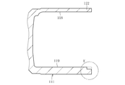
- FIG. 19 illustrates a double offset type constant velocity universal joint.
- the constant velocity universal joint includes an outer joint member 111, an inner joint member 112, a plurality of balls 113, and a cage 114.
- linear track grooves 118 extending in the axial direction are formed at a plurality of locations on the inner peripheral surface 119.
- linear track grooves 120 extending in the axial direction are formed at a plurality of locations on the outer peripheral surface 121 in pairs with the track grooves 118 of the outer joint member 111.
- the ball 113 is interposed between the track groove 118 of the outer joint member 111 and the track groove 120 of the inner joint member 112.
- the cage 114 is disposed between the inner peripheral surface 119 of the outer joint member 111 and the outer peripheral surface 121 of the inner joint member 112.
- This constant velocity universal joint has a structure in which an inner part 115 composed of an inner joint member 112, a ball 113 and a cage 114 is accommodated in the outer joint member 111 so as to be slidable in the axial direction.
- This constant velocity universal joint has a structure in which one shaft end portion of the shaft 117 is inserted into the shaft hole 116 of the inner joint member 112 and is spline-fitted.
- a drive shaft is configured by coupling the inner joint member of the fixed type constant velocity universal joint to the other shaft end (not shown) of the shaft 117 extending from the inner joint member 112 of the sliding type constant velocity universal joint. Yes.
- the above-mentioned sliding constant velocity universal joint is assembled on the engine side (inboard side), and then the fixed constant velocity universal joint is assembled on the wheel side (outboard side). ing.
- the wheel bearing is assembled to the fixed constant velocity universal joint, and is assembled to the suspension device of the vehicle body by the knuckle.
- the fixed constant velocity universal joint of the drive shaft is not assembled to the wheel bearing on the wheel side.
- the weight of the fixed type constant velocity universal joint and the drive shaft composed of the shaft may become a heavy load and may be applied in the slide-out direction.
- a conventional sliding type constant velocity universal joint employs a retaining mechanism 125 that regulates the amount of axial displacement of the internal component 115 accommodated in the outer joint member 111 (for example, see Patent Document 1).
- a concave annular groove 123 is provided on the inner peripheral surface 119 of the opening end 122 of the outer joint member 111, and a circlip is provided in the annular groove 123.
- a retaining mechanism 125 with 124 is fitted.
- the ball 113 of the internal component 115 interferes with the circlip 124 as shown in FIG.
- the ball 113 by restricting the axial displacement amount of the ball 113, sliding over of the internal component 115 relative to the outer joint member 111 is prevented.
- the annular groove 123 into which the circlip 124 is fitted has a substantially rectangular cross section formed on the inner peripheral surface 119 of the outer joint member 111.
- the annular groove 123 is formed deeply (see D 0 in the drawing)
- the diameter of the circlip 124 is increased. It is difficult to improve workability in assembling and removing 124.
- the annular groove 123 of the retaining mechanism 125 described above is manufactured in the following manner. That is, the annular groove 123 first processes the open end 122 of the outer joint member 111 with the turning tip 129 as shown in FIGS. 24 and 25 (see the arrow in FIG. 25). Next, as shown in FIGS. 26A, 26B, and 27, the processed surface of the open end 122 of the outer joint member 111 is processed by the cut-off tool 130 (see the arrow in FIG. 27).
- the annular groove 123 having a substantially rectangular cross section is formed by the machining with the turning tip 129 and the machining with the parting tool 130, and the annular groove 123 is formed by the processing with the turning chip 129 and the process with the parting tool 130. These two steps are required.
- the present invention has been proposed in view of the above-described problems, and the object of the present invention is to provide a lightweight and compact slide that can secure the strength of the annular groove in the retaining mechanism and improve the assembly of the retaining ring.
- a dynamic constant velocity universal joint and a manufacturing method thereof are provided.
- the present invention includes a cup-shaped outer joint member and an inner joint member that transmits torque while allowing angular displacement between the outer joint member and the outer joint member, and includes the rolling element and the inner joint member.
- the sliding type constant velocity universal joint in which the internal part is accommodated in the outer joint member so as to be axially slidable and the manufacturing method thereof have the following characteristics.
- the sliding type constant velocity universal joint forms an annular groove on the inner peripheral surface of the opening end portion of the outer joint member, and is fitted into the annular groove.
- a retaining mechanism that restricts the axial displacement amount of the internal parts by causing the rolling elements to interfere with the retaining ring formed is provided, and the annular groove of the retaining mechanism is at the contact point between the rolling elements and the retaining ring.
- a conical surface that is inclined with respect to the axial direction so as to have a wedge angle that expands from the opening end of the outer joint member toward the back side is formed between the axial tangent and the outer joint member.
- a wedge angle is formed between the axial tangent at the contact point between the rolling element and the retaining ring and the conical surface of the annular groove so as to expand from the opening end of the outer joint member toward the back side.
- a retaining mechanism is provided.
- the slide end portion position where the rolling element of the internal part comes into contact with and interferes with the retaining ring is close to the opening end portion of the outer joint member. It becomes a part.
- the axial direction dimension of an outer joint member can be shortened conventionally, the reduction of the raw material and weight of an outer joint member can be aimed at, and the lightweight compactization of a constant velocity universal joint becomes easy.
- annular groove having a conical surface with a wedge angle as described above, the annular groove into which the retaining ring is fitted can be formed shallowly.
- the amount of diameter reduction of the retaining ring can be reduced as compared with the prior art, so that the workability in assembly and removal of the retaining ring can be improved.
- the outer diameter of the retaining ring becomes larger than the inner diameter of the track groove bottom of the outer joint member.
- the amount of rolling element interference with the retaining ring can be made smaller than before, and the inner part with respect to the outer joint member is elastically deformed at the open end of the outer joint member with the retaining ring fitted in the annular groove. Can be inserted and removed.
- the assembly process can be easily simplified, and the assembly process can be automated by the simplification.
- the retaining mechanism in the present invention has a structure in which the internal part can be inserted into and removed from the outer joint member by making the amount of interference of the rolling element with respect to the retaining ring smaller than the amount of elastic deformation of the opening end of the outer joint member. desirable.
- the annular groove of the retaining mechanism in the present invention preferably has a structure in which a cylindrical surface extending from the conical surface toward the back side of the outer joint member and in contact with the retaining ring is formed. If such a structure is adopted, the groove bottom inner diameter of the annular groove can be reduced. Thereby, the strength of the annular groove in the retaining mechanism can be ensured, and the machining allowance in the processing of the annular groove can be reduced.
- the retaining mechanism according to the present invention is set such that the axial dimension from the contact point between the retaining ring and the cylindrical surface to the inner end surface of the annular groove is longer than the radius of the wire constituting the retaining ring.
- a structure is desirable. By adopting such a structure, the retaining ring that interferes with the rolling element can be reliably brought into contact with the cylindrical surface of the annular groove.
- the retaining mechanism in the present invention is such that the inner diameter of the annular groove in the axial direction is larger than the inner diameter of the retaining ring when fitted into the annular groove, and more than the inner diameter at the contact point between the retaining ring and the annular groove. Also, a structure that is set to be small is desirable. If such a structure is adopted, the retaining ring can be securely held in the annular groove, and the rolling elements can be reliably interfered with the retaining ring.
- the inner diameter of the annular groove in the axial direction is set to be larger than the inner diameter of the retaining ring in the state where the annular groove is fitted over the entire circumference of the opening end of the outer joint member.
- the structure is desirable. If such a structure is employ
- annular groove is formed on the inner peripheral surface of the opening end portion of the outer joint member, and a retaining ring for interfering with the rolling elements is fitted.
- the groove is inclined with respect to the axial direction so as to have a wedge angle that expands from the opening end of the outer joint member toward the back side between the axial tangent at the contact point between the rolling element and the retaining ring.
- the conical surface is formed only by machining with a turning tip.
- the annular groove having the conical surface with the wedge angle as described above is formed only by machining with the turning tip, the formation of the annular groove can be performed by one step of machining with the turning tip. Can be reduced.
- the annular groove extends from the conical surface toward the back side of the outer joint member, and the cylindrical surface in contact with the retaining ring is formed only by machining with a turning tip. In this way, since the formation of the annular groove composed of the conical surface and the cylindrical surface is a single step of processing with the turning tip, the number of processing steps can be reduced.
- the annular groove can be provided in a portion close to the opening end of the outer joint member while ensuring the strength of the annular groove, the axial dimension of the outer joint member can be shortened. As a result, the material and weight of the outer joint member can be reduced, and the constant velocity universal joint can be easily reduced in weight and size.
- the annular groove into which the retaining ring is fitted can be formed shallowly, when the retaining ring is assembled to the annular groove, the diameter of the retaining ring can be reduced. Thereby, the workability
- the formation of the annular groove into which the retaining ring is fitted can be done by one step of machining with a turning tip, the number of machining steps can be reduced.
- FIG. 7B is a cross-sectional view taken along the line PP of FIG.
- FIG. 7A showing the annular groove formed in the outer joint member of FIG.
- FIG. 9B is a cross-sectional view taken along line QQ in FIG. 9A, showing another example of the annular groove formed in the outer joint member.
- FIG. 9B is a cross-sectional view taken along line QQ in FIG. 9A, showing another example of the annular groove formed in the outer joint member.
- C section of Drawing 9B it is a principal part expanded sectional view which shows the state which the internal components interfered with the retaining mechanism by axial displacement.
- G section of FIG. It is the side view which showed the annular groove formed in the outer joint member of FIG.
- FIG. 13B is a cross-sectional view taken along line SS of FIG. 13A, showing an annular groove formed in the outer joint member. It is an expanded sectional view of H section of Drawing 13B. It is the side view which showed the other example of the annular groove formed in an outer joint member, and looked at the outer joint member from the opening side.
- FIG. 15B is a cross-sectional view taken along line TT in FIG. 15A, showing another example of the annular groove formed in the outer joint member. It is an expanded sectional view of I section of Drawing 15B. It is sectional drawing which shows the whole structure of a cross groove type constant velocity universal joint in other embodiment of this invention.
- FIG. 18 is a cross-sectional view illustrating a state in which the internal component of FIG. 17 interferes with a retaining mechanism due to axial displacement. It is sectional drawing which shows the whole structure of the conventional sliding type constant velocity universal joint.
- FIG. 20 is a cross-sectional view illustrating a state in which the internal component of FIG. 19 interferes with a retaining mechanism due to axial displacement. It is a principal part expanded sectional view of FIG. It is an expanded sectional view of D section of FIG.
- FIG. 20 is a cross-sectional view showing a state in which an internal part and a retaining ring are assembled to the outer joint member of FIG. 19. It is sectional drawing which shows the state before forming an annular groove in the outer joint member of FIG.
- FIG. 26 is a cross-sectional view taken along the line RR in FIG. 26A, showing the annular groove formed in the outer joint member of FIG. It is an expanded sectional view of F section of Drawing 26B.
- the present invention is also applicable to other sliding type constant velocity universal joints such as a tripod type constant velocity universal joint (TJ) using a roller as a rolling element.
- DOJ double offset type constant velocity universal joint
- LJ cross groove type constant velocity universal joint
- TJ tripod type constant velocity universal joint
- a drive shaft that transmits power from an automobile engine to a wheel needs to cope with angular displacement and axial displacement due to a change in the relative positional relationship between the engine and the wheel.
- the drive shaft generally has a sliding type constant velocity universal joint that allows both axial displacement and angular displacement on the engine side (inboard side), and only angular displacement on the wheel side (outboard side).
- Each of the fixed constant velocity universal joints to be allowed is mounted, and both constant velocity universal joints are connected by a shaft.
- FIG. 1 shows an overall configuration of a double offset type constant velocity universal joint (hereinafter simply referred to as a constant velocity universal joint) which is one of the sliding type constant velocity universal joints assembled to the drive shaft.
- a constant velocity universal joint hereinafter simply referred to as a constant velocity universal joint
- the constant velocity universal joint of this embodiment includes a cup-shaped outer joint member 11, an inner joint member 12, a plurality of balls 13 that are rolling elements, and a cage 14.
- An internal component 15 including an inner joint member 12, a ball 13 and a cage 14 is accommodated in the outer joint member 11 so as to be axially displaceable.
- One shaft end portion of the shaft 17 is coupled to the shaft hole 16 of the inner joint member 12 by spline fitting.
- a drive shaft is configured by coupling an inner joint member of a fixed type constant velocity universal joint to the other shaft end portion (not shown) of the shaft 17 extending from the inner joint member 12.
- linear track grooves 18 extending in the axial direction are formed at equal intervals in a plurality of locations in the circumferential direction of the inner peripheral surface 19.
- linear track grooves 20 extending in the axial direction are paired with the track grooves 18 of the outer joint member 11 and are formed at a plurality of positions in the circumferential direction of the outer peripheral surface 21 at equal intervals.
- the ball 13 is disposed between the track groove 18 of the outer joint member 11 and the track groove 20 of the inner joint member 12 to transmit rotational torque.
- the cage 14 is interposed between the inner peripheral surface 19 of the outer joint member 11 and the outer peripheral surface 21 of the inner joint member 12 to hold the ball 13.
- a concave annular groove 23 is provided in the track groove 18 and the inner peripheral surface 19 of the opening end 22 of the outer joint member 11, and the annular groove 23 is provided.
- a retaining mechanism 25 having a circlip 24 as a retaining ring fitted thereto is employed.
- the ball 13 of the internal part 15 interferes with the circlip 24 as shown in FIG. This restricts the amount of axial displacement of the ball 13. Thereby, the slide-over which the internal component 15 jumps out from the opening end part 22 of the outer joint member 11 is prevented.
- the weight of the fixed constant velocity universal joint and the drive shaft consisting of the shaft is applied as a heavy load in the slide-out direction of the constant velocity universal joint. Even if it exists, the ball 13 of the internal component 15 interferes with the circlip 24, so that the slide-over of the internal component 15 can be reliably prevented. As a result, the drive shaft can be easily assembled.
- the retaining mechanism 25 employed in the constant velocity universal joint of this embodiment has the following specific configuration.
- the retaining mechanism 25 of this embodiment is formed in the track groove 18 and the inner peripheral surface 19 of the opening end 22 of the outer joint member 11, particularly in a portion close to the opening end surface 26.
- the annular groove 23 and the circlip 24 fitted in the annular groove 23 are configured.
- FIGS. 3 and 4 show a state in which the ball 13 contacts and interferes with the circlip 24 due to the axial displacement of the internal component 15.
- the annular groove 23 of the retaining mechanism 25 extends from the open end 22 of the outer joint member 11 between the ball 13 and the circlip 24 at the axial tangent L 1 at the contact point ⁇ .
- a conical surface 27 inclined with respect to the axial direction is formed so as to have a wedge angle ⁇ that expands toward the back side. This conical surface 27 is in a positional relationship with the axial tangent L 2 at the contact point ⁇ with the circlip 24.
- the annular groove 23 includes the aforementioned conical surface 27 and an end surface 28 extending from the track groove 18 of the outer joint member 11 in a direction orthogonal to the axial direction.
- the circlip 24 is held in the annular groove 23 in a state where it contacts the conical surface 27 and the end surface 28 in the annular groove 23 and is sandwiched between the conical surface 27 and the end surface 28.
- the wedge angle ⁇ should be set in the range of 5 ° to 25 °.
- the holding force becomes insufficient and it becomes difficult to reliably prevent the slide over.
- the wedge angle ⁇ is larger than 25 °, the load direction applied from the circlip 24 to the annular groove 23 of the outer joint member 11 is close to the sliding direction, which is disadvantageous in terms of groove strength and makes it difficult to reduce the weight.
- axial inlet inner diameter D 1 of the annular groove 23 is larger than the inner diameter D 2 of the circlip 24 in a state of being fitted in the annular groove 23 and circlip 24 and the annular groove 23 Is set to be smaller than the inner diameter D 3 at the contact point ⁇ . Thereby, the circlip 24 can be reliably held in the annular groove 23.
- the ball 13 of the internal component 15 contacts and interferes with the circlip 24, whereby the axial direction of the ball 13 is reached.
- the amount of displacement is regulated (see FIGS. 3 and 4).
- the axial dimension H 1 between the center O 1 of the ball 13 and the open end face 26 of the outer joint member 11 is smaller than that of the conventional constant velocity universal joint (see FIG. 21).
- H 1 ⁇ H 0 the axial direction dimension of the outer joint member 11 can be made shorter than before, the material and weight of the outer joint member 11 can be reduced, and the constant velocity universal joint can be easily reduced in weight and size.
- the direction in which the pulling force acting on the conical surface 27 of the annular groove 23 from the circlip 24 is directed radially outward from the axial direction of the outer joint member 11 by the wedge angle ⁇ of the conical surface 27 of the annular groove 23.
- the axial dimension E 1 from the contact point ⁇ between the circlip 24 and the conical surface 27 to the open end surface 26 of the outer joint member 11 is made smaller than in the case of the conventional constant velocity universal joint (see FIG. 22). (E 1 ⁇ E 0 ). Also in this respect, the axial dimension of the outer joint member 11 can be shortened, and the material and weight of the outer joint member 11 can be reduced, which contributes to the light weight and compactness of the constant velocity universal joint.
- the annular groove 23 into which the circlip 24 is fitted is changed to a conventional annular groove (see FIG. 22). ) (D 4 ⁇ D 0 ).
- the difference F 1 between the inner diameter D 2 of the circlip 24 and the circumscribed circle diameter D 5 of the ball 13 is smaller than in the conventional constant velocity universal joint (see FIG. 22) (F 1 ⁇ F 0 ).
- the internal component 15 can be inserted into and removed from the outer joint member 11 by elastic deformation of the open end 22 of the outer joint member 11. That is, since the elastic deformation amount of the outer joint member 11 is larger on the opening end side than on the back side, the elastic deformation of the opening end portion 22 of the outer joint member 11 is easy. Further, the annular groove 23 into which the circlip 24 is fitted is formed in a portion close to the opening end surface 26.
- the amount of interference of the ball 13 with the circlip 24, that is, the difference F 1 between the inner diameter D 2 of the circlip 24 and the circumscribed circle diameter D 5 of the ball 13 is determined as the elasticity of the open end 22 of the outer joint member 11.
- the circlip 24 is assembled to the outer joint member 11.
- the inner part 15 is assembled to the outer joint member 11.
- the ball 13 of the internal part 15 can get over the circlip 24 with a minimum required pulling force.
- the internal component 15 can be accommodated in the outer joint member 11.
- the internal component 15 can be removed from the outer joint member 11 with the circlip 24 mounted in the annular groove 23.
- the assembly process of the circlip 24 and the internal component 15 can be simplified, and the assembly process can be automated by the simplification.
- the axial entrance inner diameter D 1 of the annular groove 23 extends over the entire circumference of the open end 22 of the outer joint member 11. Is set to be larger than the inner diameter D 2 of the circlip 24 in the state of being fitted to.
- FIG. 6 only the circlip 24 fitted in the annular groove 23 of the outer joint member 11 is shown, and the internal component 15 is not shown.
- the annular groove 23 of the retaining mechanism 25 described in the above embodiment can be manufactured in the following manner. That is, as shown in FIGS. 7A, 7B and 8, the annular groove 23 can be realized by machining the open end 22 of the outer joint member 11 with the turning tip 29 (see the arrow in FIG. 8).
- the annular groove 23 having the conical surface 27 with the wedge angle ⁇ as described above is formed only by the machining with the turning tip 29, the formation of the annular groove 23 can be performed by one step of the machining with the turning tip 29. Therefore, the number of processing steps can be reduced as compared with the prior art.
- the opening end 22 of the outer joint member 11 is turned to the inner peripheral surface 19 of the outer joint member 11 by the turning tip 29 (see FIG. 7).
- the opening end 22 of the outer joint member 11 is not turned to the inner peripheral surface 19 of the outer joint member 11 by the turning tip 29, and the opening end face 26 is removed. Only turning may be performed (see the arrow in FIG. 10).
- the annular groove 53 of the retaining mechanism 55 shown in FIGS. 11 and 12 includes the aforementioned conical surface 27 and a cylindrical surface that extends from the conical surface 27 toward the back side of the outer joint member 11 and contacts the circlip 24. And 50.
- the circlip 24 is held in the annular groove 53 in a state where the circlip 24 is in contact with the conical surface 27 and the cylindrical surface 50 in the annular groove 53.
- the groove bottom inner diameter of the annular groove 53 can be made smaller than that in the case of only the conical surface 27 (see FIG. 4). . That is, since the thickness at the opening end 22 of the outer joint member 11 can be increased, the strength of the annular groove 53 in the retaining mechanism 55 can be ensured, and the machining allowance in processing of the annular groove 53 can be ensured. Can be reduced.
- the axial dimension G from the contact point ⁇ between the circlip 24 and the cylindrical surface 50 to the back end surface 28 of the annular groove 53 is the radius of the wire constituting the circlip 24. It is set to be longer than R. Thereby, the circlip 24 that interferes with the ball 13 can be reliably brought into contact with the cylindrical surface 50 of the annular groove 53.
- the annular groove 53 of the retaining mechanism 55 described in the above embodiment can be manufactured in the following manner. That is, the annular groove 53 can be realized by machining the open end 22 of the outer joint member 11 with the turning tip 29 as shown in FIGS. 13A, 13B, and 14 (see the arrow in FIG. 14).
- the annular groove 53 having the conical surface 27 and the cylindrical surface 50 with the wedge angle ⁇ as described above is formed only by the machining with the turning tip 29, so that the formation of the annular groove 53 is one of the machining with the turning tip 29. Since the process is sufficient, the number of processing steps can be reduced as compared with the prior art.
- the opening end 22 of the outer joint member 11 is turned to the inner peripheral surface 19 of the outer joint member 11 by the turning tip 29 to form the annular groove 53.
- the open end 22 of the outer joint member 11 is turned to the inner peripheral surface 19 of the outer joint member 11 by a turning tip 29.
- the annular groove 53 may be formed by turning only the opening end face 26 without turning (see the arrow in FIG. 16).
- this constant velocity universal joint includes a cup-shaped outer joint member 31, an inner joint member 32, a plurality of balls 33 which are rolling elements, and a cage.
- An inner part 35 including an inner joint member 32, a ball 33, and a cage 34 is accommodated in the outer joint member 31 so as to be axially displaceable.
- the shaft end portion of the shaft 37 is coupled to the shaft hole 36 of the inner joint member 32 by spline fitting.
- the outer joint member 31 is formed at equal intervals at a plurality of locations in the circumferential direction of the inner peripheral surface 39 with linear track grooves 38 extending in the axial direction alternately inclined in the opposite direction with respect to the axis.
- the inner joint member 32 is formed at equal intervals at a plurality of locations in the circumferential direction of the outer peripheral surface 41 with the linear track grooves 40 extending in the axial direction inclined in the opposite direction to the track grooves 38 of the outer joint member 31.
- the ball 33 is incorporated at the intersection of the track groove 38 of the outer joint member 31 and the track groove 40 of the inner joint member 32 to transmit rotational torque.
- the cage 34 is interposed between the inner peripheral surface 39 of the outer joint member 31 and the outer peripheral surface 41 of the inner joint member 32 and holds the balls 33.
- a concave annular groove 43 is provided in the track groove 38 and the inner peripheral surface 39 of the open end 42 of the outer joint member 31, and the annular groove 43 is provided in the annular groove 43.
- a retaining mechanism 45 fitted with a circlip 44 is applicable.
- the retaining mechanism 45 has the same configuration and function as the retaining mechanisms 25 and 55 in the constant velocity universal joint shown in FIGS.
Landscapes
- Engineering & Computer Science (AREA)
- General Engineering & Computer Science (AREA)
- Mechanical Engineering (AREA)
- Snaps, Bayonet Connections, Set Pins, And Snap Rings (AREA)
Abstract
カップ状の外側継手部材11と、その外側継手部材11との間でボール13を介して角度変位を許容しながらトルクを伝達する内側継手部材とを備え、ボール13および内側継手部材を含む内部部品が外側継手部材11に軸方向摺動自在に収容された摺動式等速自在継手であって、外側継手部材11の開口端部22の内周面に環状溝23を形成し、その環状溝23に嵌着されたサークリップ24にボール13を干渉させることにより、内部部品の軸方向変位量を規制する抜け止め機構25を具備し、その抜け止め機構25の環状溝23は、ボール13とサークリップ24との接触点αでの軸方向接線L1との間で、外側継手部材11の開口端部22から奥側に向けて拡開する楔角度θを持つように軸方向に対して傾斜した円錐面27が形成されている。
Description
本発明は、自動車や各種産業機械などの動力伝達系において使用され、特に、自動車用ドライブシャフトやプロペラシャフトに組み込まれる摺動式等速自在継手及びその製造方法に関する。
自動車のエンジンから車輪に回転力を等速で伝達するドライブシャフトやプロペラシャフトに組み込まれる等速自在継手には、固定式等速自在継手と摺動式等速自在継手の二種がある。これら両者の等速自在継手は、駆動側と従動側の二軸を連結してその二軸が作動角をとっても等速で回転トルクを伝達し得る構造を備えている。
ドライブシャフトは、エンジンと車輪との相対的位置関係の変化による角度変位と軸方向変位に対応する必要がある。そのため、ドライブシャフトは、一般的に、エンジン側(インボード側)に摺動式等速自在継手を、車輪側(アウトボード側)に固定式等速自在継手をそれぞれ装備し、両者の等速自在継手をシャフトで連結した構造を具備する。
ドライブシャフトに組み付けられる摺動式等速自在継手の一つに、回転トルクを伝達する転動体としてボールを用いたダブルオフセット型等速自在継手(DOJ)やクロスグルーブ型等速自在継手(LJ)がある。また、他の摺動式等速自在継手には、転動体としてローラを用いたトリポード型等速自在継手(TJ)がある。
図19は、ダブルオフセット型等速自在継手を例示する。この等速自在継手は、外側継手部材111と、内側継手部材112と、複数個のボール113と、ケージ114とを備えている。
外側継手部材111は、軸方向に延びる直線状のトラック溝118が内周面119の複数箇所に形成されている。内側継手部材112は、軸方向に延びる直線状のトラック溝120が外側継手部材111のトラック溝118と対をなして外周面121の複数箇所に形成されている。ボール113は、外側継手部材111のトラック溝118と内側継手部材112のトラック溝120との間に介在する。ケージ114は、外側継手部材111の内周面119と内側継手部材112の外周面121との間に配されている。
この等速自在継手は、内側継手部材112、ボール113およびケージ114からなる内部部品115が外側継手部材111に軸方向摺動自在に収容された構造を具備する。この等速自在継手は、内側継手部材112の軸孔116にシャフト117の一方の軸端部を挿入してスプライン嵌合させた構造を具備する。この摺動式等速自在継手の内側継手部材112から延びるシャフト117の他方の軸端部(図示せず)に固定式等速自在継手の内側継手部材を結合させることによりドライブシャフトを構成している。
ここで、ドライブシャフトを車体に組み付けるに際しては、前述の摺動式等速自在継手をエンジン側(インボード側)に組み付けた後、固定式等速自在継手を車輪側(アウトボード側)に組み付けている。その車輪側では、固定式等速自在継手に車輪用軸受を組み付け、ナックルにより車体の懸架装置に組み付ける。
ドライブシャフトの摺動式等速自在継手を車体のエンジン側に組み付けた時点では、固定式等速自在継手が車輪側の車輪用軸受に組み付けられていない。そのため、摺動式等速自在継手には、固定式等速自在継手およびシャフトからなるドライブシャフトの自重が大きな荷重となってスライドアウト方向へかかる場合がある。
このような状態になると、摺動式等速自在継手の内部部品115が外側継手部材111の開口端部122から飛び出すスライドオーバーが生じることがある。このようなスライドオーバーを防止するため、従来の摺動式等速自在継手では、外側継手部材111に収容された内部部品115の軸方向変位量を規制する抜け止め機構125が採用されている(例えば、特許文献1参照)。
前述の特許文献1で開示された従来の摺動式等速自在継手では、外側継手部材111の開口端部122の内周面119に凹状の環状溝123を設け、その環状溝123にサークリップ124を嵌着した抜け止め機構125を採用している。
この抜け止め機構125では、ドライブシャフトを車体に組み付けるに際して、内部部品115に大きな荷重がスライドアウト方向へかかった場合、図20に示すように、内部部品115のボール113がサークリップ124と干渉することでボール113の軸方向変位量を規制することにより、外側継手部材111に対する内部部品115のスライドオーバーを防止するようにしている。
この特許文献1で開示された抜け止め機構125では、外側継手部材111の開口端部122から奥側へ入り込んだ厚肉部の内周面119に、サークリップ124が嵌着される環状溝123を形成した構造を具備する。これにより、外側継手部材111の開口端部122までの肉厚を確保することで環状溝123の強度を確保するようにしている。
しかしながら、この抜け止め機構125の場合、図21に示すように、内部部品115のボール113がサークリップ124と接触して干渉するスライド端部位置が、外側継手部材111の開口端部122から奥側へ大きく離隔した部位となっている(図中のH0参照)。その分だけ、外側継手部材111の軸方向寸法が長くなり、外側継手部材111の素材および重量の削減が困難となって等速自在継手の軽量コンパクト化が難しい。
また、図22に示すように、サークリップ124が嵌着される環状溝123は、外側継手部材111の内周面119に形成された断面略矩形状をなす。このように、環状溝123を深く形成していることから(図中のD0参照)、サークリップ124を環状溝123に組み付けるに際して、サークリップ124の縮径量が大きくなることから、サークリップ124の組み付けおよび取り外しにおける作業性の向上が困難である。
また、環状溝123に嵌着されたサークリップ124の内径寸法とボール113の外接円径との差F0を大きくすることにより、サークリップ124に対してボール113が乗り越えられない干渉量を確保することで強固な抜け止めとしている。そのため、図23に示すように、外側継手部材111に内部部品115を組み込んだ後にサークリップ124を環状溝123に嵌め込まなければならない。その結果、組み立て工程が複雑となり、その組み立てを手作業で行わなければならない。
前述した抜け止め機構125の環状溝123は、以下の要領でもって製作される。つまり、環状溝123は、まず、図24および図25に示すように、外側継手部材111の開口端部122を旋削チップ129により加工する(図25の矢印参照)。次に、図26A、図26Bおよび図27に示すように、外側継手部材111の開口端部122の加工面を突っ切りバイト130により加工する(図27の矢印参照)。
このように、断面略矩形状をなす環状溝123を旋削チップ129による加工と突っ切りバイト130による加工で形成することにより、環状溝123の形成には、旋削チップ129による加工と突っ切りバイト130による加工の二工程を必要とする。
そこで、本発明は前述の問題点に鑑みて提案されたもので、その目的とするところは、抜け止め機構における環状溝の強度を確保すると共に止め輪の組み付け性を向上させ得る軽量コンパクトな摺動式等速自在継手及びその製造方法を提供することにある。
本発明は、カップ状の外側継手部材と、その外側継手部材との間で転動体を介して角度変位を許容しながらトルクを伝達する内側継手部材とを備え、転動体および内側継手部材を含む内部部品が外側継手部材に軸方向摺動自在に収容された摺動式等速自在継手及びその製造方法について、以下の特徴を有する。
前述の目的を達成するための技術的手段として、本発明に係る摺動式等速自在継手は、外側継手部材の開口端部の内周面に環状溝を形成し、その環状溝に嵌着された止め輪に転動体を干渉させることにより、内部部品の軸方向変位量を規制する抜け止め機構を具備し、その抜け止め機構の環状溝は、転動体と止め輪との接触点での軸方向接線との間で、外側継手部材の開口端部から奥側に向けて拡開する楔角度を持つように軸方向に対して傾斜した円錐面が形成されていることを特徴とする。
本発明では、転動体と止め輪との接触点での軸方向接線と環状溝の円錐面との間で、外側継手部材の開口端部から奥側に向けて拡開する楔角度が形成された抜け止め機構を具備する。これにより、環状溝に嵌着されて円錐面と接する止め輪に転動体を干渉させることで、内部部品の軸方向変位量を確実に規制することができる。
また、前述のような楔角度の円錐面を持つ環状溝としたことにより、内部部品の転動体が止め輪と接触して干渉するスライド端部位置が、外側継手部材の開口端部から近接した部位となる。これにより、外側継手部材の軸方向寸法を従来よりも短くすることができ、外側継手部材の素材および重量の削減が図れて等速自在継手の軽量コンパクト化が容易となる。
さらに、前述のような楔角度の円錐面を持つ環状溝としたことにより、止め輪が嵌着される環状溝を浅く形成することができる。これにより、止め輪を環状溝に組み付けるに際して、止め輪の縮径量が従来よりも少なくて済むことから、止め輪の組み付けおよび取り外しにおける作業性の向上が図れる。
さらに、前述のような楔角度の円錐面を持つ環状溝としたことにより、止め輪の外径が外側継手部材のトラック溝底の内径よりも大きくなる。これにより、止め輪に対する転動体の干渉量を従来よりも小さくすることができ、止め輪を環状溝に嵌着した状態で、外側継手部材の開口端部の弾性変形により外側継手部材に対する内部部品の抜き差しが可能となる。その結果、組み立て工程の簡素化が容易となり、その簡素化により組立工程の自動化が実現できる。
本発明における抜け止め機構は、止め輪に対する転動体の干渉量を外側継手部材の開口端部の弾性変形量よりも小さくすることにより、内部部品を外側継手部材に対して抜き差し可能とした構造が望ましい。
このような構造を採用すれば、内部部品を外側継手部材に対して抜き差し可能とした構造を容易に実現することができる。
本発明における抜け止め機構の環状溝は、円錐面から外側継手部材の奥側に向けて延び、かつ、止め輪と接する円筒面が形成されている構造が望ましい。このような構造を採用すれば、環状溝の溝底内径を小さくすることができる。これにより、抜け止め機構における環状溝の強度を確保できると共に、環状溝の加工における取り代を削減できる。
本発明のおける抜け止め機構は、止め輪と円筒面との接触点から環状溝の奥側端面までの軸方向寸法が、止め輪を構成する線材の半径よりも長くなるように設定されている構造が望ましい。このような構造を採用すれば、転動体と干渉する止め輪を環状溝の円筒面に確実に接触させることができる。
本発明における抜け止め機構は、環状溝の軸方向入口内径が、環状溝に嵌着された状態での止め輪の内径よりも大きく、かつ、止め輪と環状溝との接触点での内径よりも小さくなるように設定されている構造が望ましい。このような構造を採用すれば、環状溝に止め輪を確実に保持することができると共にその止め輪に転動体を確実に干渉させることができる。
本発明における抜け止め機構は、環状溝の軸方向入口内径が、外側継手部材の開口端部の全周に亘って環状溝に嵌着された状態での止め輪の内径よりも大きく設定されている構造が望ましい。このような構造を採用すれば、環状溝に嵌着された止め輪の全周を外側継手部材の開口側から目視することができる。これにより、環状溝への止め輪の組み付け状態を確認することができ、環状溝からの止め輪の取り外しが容易となる。
本発明に係る摺動式等速自在継手の製造方法は、外側継手部材の開口端部の内周面に、転動体を干渉させるための止め輪が嵌着される環状溝を形成し、環状溝は、転動体と止め輪との接触点での軸方向接線との間で、外側継手部材の開口端部から奥側に向けて拡開する楔角度を持つように軸方向に対して傾斜した円錐面が旋削チップによる加工のみで形成されていることを特徴とする。
本発明では、前述のような楔角度の円錐面を持つ環状溝を旋削チップによる加工のみで形成することにより、環状溝の形成が旋削チップによる加工の一工程で済むため、従来よりも加工工数の削減が図れる。
本発明における環状溝は、円錐面から外側継手部材の奥側に向けて延び、かつ、止め輪と接する円筒面が、旋削チップによる加工のみで形成されていることが望ましい。このようにすれば、円錐面および円筒面からなる環状溝の形成が旋削チップによる加工の一工程で済むため、加工工数の削減が図れる。
本発明によれば、環状溝の強度を確保しつつ、外側継手部材の開口端部から近接した部位に環状溝を設けることができるので、外側継手部材の軸方向寸法の短縮化が図れる。これにより、外側継手部材の素材および重量の削減が図れて等速自在継手の軽量コンパクト化が容易となる。
また、止め輪が嵌着される環状溝を浅く形成することができるので、止め輪を環状溝に組み付けるに際して、止め輪の縮径量が少なくて済む。これにより、止め輪の組み付けおよび取り外しにおける作業性の向上が図れる。
さらに、止め輪が嵌着される環状溝の形成が旋削チップによる加工の一工程で済むため、加工工数の削減が図れる。
本発明に係る摺動式等速自在継手の実施形態を図面に基づいて以下に詳述する。
以下の実施形態では、回転トルクを伝達する転動体としてボールを用いたダブルオフセット型等速自在継手(DOJ)やクロスグルーブ型等速自在継手(LJ)に適用した場合を例示する。本発明は、転動体としてローラを用いたトリポード型等速自在継手(TJ)などの他の摺動式等速自在継手にも適用可能である。
自動車のエンジンから車輪に動力を伝達するドライブシャフトは、エンジンと車輪との相対的位置関係の変化による角度変位と軸方向変位に対応する必要がある。そのため、ドライブシャフトは、一般的に、エンジン側(インボード側)に軸方向変位および角度変位の両方を許容する摺動式等速自在継手を、車輪側(アウトボード側)に角度変位のみを許容する固定式等速自在継手をそれぞれ装着し、両者の等速自在継手をシャフトで連結した構造を具備する。
図1は、前述のドライブシャフトに組み付けられた摺動式等速自在継手の一つであるダブルオフセット型等速自在継手(以下、単に等速自在継手と称す)の全体構成を示す。
この実施形態の等速自在継手は、カップ状の外側継手部材11と、内側継手部材12と、転動体である複数個のボール13と、ケージ14とを備えている。内側継手部材12、ボール13およびケージ14からなる内部部品15が外側継手部材11に軸方向変位可能に収容されている。内側継手部材12の軸孔16にシャフト17の一方の軸端部がスプライン嵌合により結合されている。この内側継手部材12から延びるシャフト17の他方の軸端部(図示せず)に固定式等速自在継手の内側継手部材を結合させることによりドライブシャフトを構成している。
外側継手部材11は、軸方向に延びる直線状トラック溝18が内周面19の円周方向複数箇所に等間隔で形成されている。内側継手部材12は、軸方向に延びる直線状トラック溝20が外側継手部材11のトラック溝18と対をなして外周面21の円周方向複数箇所に等間隔で形成されている。ボール13は、外側継手部材11のトラック溝18と内側継手部材12のトラック溝20との間に配されて回転トルクを伝達する。ケージ14は、外側継手部材11の内周面19と内側継手部材12の外周面21との間に介在してボール13を保持する。
この等速自在継手では、シャフト17により外側継手部材11と内側継手部材12との間に作動角が付与されると、ケージ14に保持されたボール13は常にどの作動角においても、その作動角の二等分面内に維持され、外側継手部材11と内側継手部材12との間での等速性が確保される。また、ケージ14に保持されたボール13が外側継手部材11のトラック溝18上を転動することにより、外側継手部材11に対して内部部品15が軸方向摺動自在となっている。
なお、この等速自在継手では、図示しないが、継手内部に封入されたグリース等の潤滑剤の漏洩を防止すると共に継手外部からの異物侵入を防止するため、樹脂製あるいはゴム製の伸縮自在な蛇腹状ブーツを外側継手部材11とシャフト17との間に張設することにより、外側継手部材11の開口端部22を閉塞している。
以上の構成からなる等速自在継手が組み付けられたドライブシャフトを車体に組み付けるに際して、固定式等速自在継手およびシャフトからなるドライブシャフトの自重が大きな荷重として等速自在継手のスライドアウト方向へかかる場合がある。そのため、内部部品15が外側継手部材11の開口端部22から飛び出すスライドオーバーを防止する必要がある。
そこで、この実施形態の等速自在継手は、図1に示すように、外側継手部材11の開口端部22のトラック溝18および内周面19に凹状の環状溝23を設け、その環状溝23に止め輪であるサークリップ24を嵌着した抜け止め機構25を採用している。
この抜け止め機構25では、ドライブシャフトを車体に組み付けるに際して、内部部品15に大きな荷重がスライドアウト方向へかかった場合、図2に示すように、内部部品15のボール13がサークリップ24と干渉することでボール13の軸方向変位量を規制する。これにより、内部部品15が外側継手部材11の開口端部22から飛び出すスライドオーバーを防止する。
特に、この等速自在継手が組み付けられたドライブシャフトを車体に組み付けるに際して、固定式等速自在継手およびシャフトからなるドライブシャフトの自重が大きな荷重として等速自在継手のスライドアウト方向にかかった場合であっても、内部部品15のボール13がサークリップ24と干渉することで、その内部部品15のスライドオーバーを確実に防止することができる。その結果、ドライブシャフトの組み付け性が向上する。
この実施形態の等速自在継手で採用された抜け止め機構25は、以下のような具体的構成を具備する。
この実施形態の抜け止め機構25は、図1および図2に示すように、外側継手部材11の開口端部22のトラック溝18および内周面19、特に、開口端面26に近接する部位に形成された環状溝23と、その環状溝23に嵌着されたサークリップ24とで構成されている。ここで、図3および図4は、内部部品15の軸方向変位によりボール13がサークリップ24に接触して干渉した状態を示す。
同図に示すように、抜け止め機構25の環状溝23は、ボール13とサークリップ24との接触点αでの軸方向接線L1との間で、外側継手部材11の開口端部22から奥側に向けて拡開する楔角度θを持つように軸方向に対して傾斜した円錐面27が形成されている。この円錐面27は、サークリップ24との接触点βでの軸方向接線L2と一致した位置関係にある。
環状溝23は、前述の円錐面27と、外側継手部材11のトラック溝18から軸方向と直交する方向に延びる端面28とを備えている。サークリップ24は、環状溝23において円錐面27と端面28とに接触して円錐面27と端面28との間に挟み込まれた状態で環状溝23に保持されている。
なお、楔角度θは5°~25°の範囲に設定するのが良い。楔角度θが5°より小さくなると、保持力が十分でなくなりスライドオーバーを確実に防止することが困難となる。一方、楔角度θが25°より大きくなると、サークリップ24から外側継手部材11の環状溝23にかかる荷重方向がスライド方向に近くなり、溝強度の点で不利となり重量削減が困難となる。
この抜け止め機構25では、環状溝23の軸方向入口内径D1が、環状溝23に嵌着された状態でのサークリップ24の内径D2よりも大きく、かつ、サークリップ24と環状溝23との接触点βでの内径D3よりも小さくなるように設定されている。これにより、環状溝23にサークリップ24を確実に保持することができる。
以上の構成からなる抜け止め機構25では、内部部品15に大きな荷重がスライドアウト方向へかかった場合、内部部品15のボール13がサークリップ24と接触して干渉することにより、ボール13の軸方向変位量を規制する(図3および図4参照)。
この時、ボール13とサークリップ24との接触点αでの軸方向接線L1と、サークリップ24と環状溝23の円錐面27との接触点βでの軸方向接線L2とが、外側継手部材11の開口端部22から奥側に向けて拡開する楔角度θをなす。これにより、環状溝23に保持された状態のサークリップ24にボール13を干渉させることで、内部部品15の軸方向変位量を確実に規制することができる。
また、前述のような楔角度θの円錐面27を持つ環状溝23としたことにより、内部部品15のボール13がサークリップ24と接触して干渉するスライド端部位置が、外側継手部材11の開口端部22から近接した部位となる。
つまり、図3に示すように、ボール13の中心O1と外側継手部材11の開口端面26との軸方向寸法H1が、従来の等速自在継手の場合(図21参照)よりも小さくなる(H1<H0)。これにより、外側継手部材11の軸方向寸法を従来よりも短くすることができ、外側継手部材11の素材および重量の削減が図れて等速自在継手の軽量コンパクト化が容易となる。
このように、環状溝23の円錐面27の楔角度θにより、サークリップ24から環状溝23の円錐面27に作用する抜け力が、外側継手部材11の軸方向よりも径方向外側へ向く方が大きくなってサークリップ24の中心O2から円錐面27との接触点βに向けて作用するため、前述のように環状溝23が外側継手部材11の開口端部22から近接した部位に形成されていても、その環状溝23の強度を確保することができる。
その結果、サークリップ24と円錐面27との接触点βから外側継手部材11の開口端面26までの軸方向寸法E1を従来の等速自在継手の場合(図22参照)よりも小さくすることができる(E1<E0)。この点でも、外側継手部材11の軸方向寸法を短くすることができ、外側継手部材11の素材および重量の削減が図れて等速自在継手の軽量コンパクト化に寄与する。
さらに、前述のような楔角度θの円錐面27を持つ環状溝23としたことにより、図4に示すように、サークリップ24が嵌着される環状溝23を従来の環状溝(図22参照)よりも浅く形成することができる(D4<D0)。これにより、サークリップ24を環状溝23に組み付けるに際して、サークリップ24の縮径量が従来よりも少なくて済むことから、サークリップ24の組み付けおよび取り外しにおける作業性の向上が図れる。また、サークリップ24の内径D2とボール13の外接円径D5との差F1が従来の等速自在継手の場合(図22参照)よりも小さくなっている(F1<F0)。
その結果、サークリップ24を環状溝23に嵌着した状態で、外側継手部材11の開口端部22の弾性変形により外側継手部材11に対する内部部品15の抜き差しが可能となる。つまり、外側継手部材11の弾性変形量は、奥側に比べて開口端部側が大きいため、外側継手部材11の開口端部22の弾性変形が容易である。また、サークリップ24が嵌着される環状溝23は、開口端面26に近接する部位に形成されている。
このようにして、サークリップ24に対するボール13の干渉量、つまり、サークリップ24の内径D2とボール13の外接円径D5との差F1を外側継手部材11の開口端部22の弾性変形量よりも小さくすることにより、外側継手部材11に対する内部部品15の抜き差しが可能となる。
従って、図5に示すように、まず、外側継手部材11に対してサークリップ24を組み付ける。その後、外側継手部材11に内部部品15を組み付ける。外側継手部材11の開口端部22を弾性変形域内で拡径させることにより、内部部品15のボール13はサークリップ24を必要最低限の抜け力で乗り越えることができる。その結果、内部部品15を外側継手部材11に収容することが可能となる。
これにより、組み立て後、外側継手部材11からの内部部品15の取り外しも、サークリップ24を環状溝23に装着した状態で行うことができる。このようにして、サークリップ24および内部部品15の組み立て工程の簡素化が容易となり、その簡素化により組立工程の自動化が実現できる。
この実施形態の抜け止め機構25では、図3および図4に示すように、環状溝23の軸方向入口内径D1が、外側継手部材11の開口端部22の全周に亘って環状溝23に嵌着された状態でのサークリップ24の内径D2よりも大きく設定されている。なお、図6では、外側継手部材11の環状溝23に嵌着されたサークリップ24のみを示し、内部部品15を図示省略している。
これにより、図6に示すように、環状溝23に嵌着された状態にあるサークリップ24の全周を外側継手部材11の開口側から目視することができる。その結果、環状溝23へのサークリップ24の組み付け状態を確認することができる。また、サークリップ24の縮径量が少ないことから、環状溝23からのサークリップ24の取り外しが容易となる。
以上の実施形態で説明した抜け止め機構25の環状溝23は、以下の要領でもって製作することが可能である。つまり、環状溝23は、図7A、図7Bおよび図8に示すように、外側継手部材11の開口端部22を旋削チップ29により加工することで実現可能である(図8の矢印参照)。
このように、前述のような楔角度θの円錐面27を持つ環状溝23を旋削チップ29による加工のみで形成することにより、環状溝23の形成が旋削チップ29による加工の一工程で済むため、従来よりも加工工数の削減が図れる。
なお、図7A、図7Bおよび図8に示す旋削チップ29による加工では、外側継手部材11の開口端部22を旋削チップ29により外側継手部材11の内周面19まで旋削しているが(図8の矢印参照)、図9A、図9Bおよび図10に示すように、外側継手部材11の開口端部22を旋削チップ29により外側継手部材11の内周面19まで旋削せず、開口端面26のみを旋削するようにしてもよい(図10の矢印参照)。
以上で説明した実施形態の抜け止め機構25(図3および図4参照)では、環状溝23を円錐面27のみで構成した場合を例示したが、図11および図12に示すような抜け止め機構55であってもよい。なお、図11および図12において、図3および図4と同一または相当部分には同一参照符号を付して重複説明は省略する。
図11および図12に示す抜け止め機構55の環状溝53は、前述した円錐面27と、その円錐面27から外側継手部材11の奥側に向けて延び、かつ、サークリップ24と接する円筒面50とで構成されている。サークリップ24は、環状溝53において円錐面27と円筒面50とに接触した状態で環状溝53に保持されている。
この実施形態の環状溝53では、円錐面27に加えて円筒面50を形成したことにより、環状溝53の溝底内径を円錐面27のみの場合(図4参照)よりも小さくすることができる。つまり、外側継手部材11の開口端部22での肉厚を大きくすることができるので、抜け止め機構55における環状溝53の強度を確保することができると共に、環状溝53の加工における取り代を削減することができる。
また、この実施形態の抜け止め機構55では、サークリップ24と円筒面50との接触点γから環状溝53の奥側端面28までの軸方向寸法Gが、サークリップ24を構成する線材の半径Rよりも長くなるように設定されている。これにより、ボール13と干渉するサークリップ24を環状溝53の円筒面50に確実に接触させることができる。
なお、この実施形態の抜け止め機構55の環状溝53における円筒面50以外の構成および作用効果については、図3および図4に示す実施形態における抜け止め機構25と同様であるため、重複説明は省略する。
以上の実施形態で説明した抜け止め機構55の環状溝53は、以下の要領でもって製作することが可能である。つまり、環状溝53は、図13A、図13Bおよび図14に示すように、外側継手部材11の開口端部22を旋削チップ29により加工することで実現可能である(図14の矢印参照)。
このように、前述のような楔角度θの円錐面27および円筒面50を持つ環状溝53を旋削チップ29による加工のみで形成することにより、環状溝53の形成が旋削チップ29による加工の一工程で済むため、従来よりも加工工数の削減が図れる。
なお、図13A、図13Bおよび図14に示す旋削チップ29による加工では、外側継手部材11の開口端部22を旋削チップ29により外側継手部材11の内周面19まで旋削して環状溝53を形成しているが(図14の矢印参照)、図15A、図15Bおよび図16に示すように、外側継手部材11の開口端部22を旋削チップ29により外側継手部材11の内周面19まで旋削せず、開口端面26のみを旋削するようにして環状溝53を形成してもよい(図16の矢印参照)。
以上の実施形態(図1および図2参照)では、ボールタイプの一つであるダブルオフセット型等速自在継手に適用した場合を例示したが、図17および図18に示す実施形態のように、他のボールタイプであるクロスグルーブ型等速自在継手にも適用可能である。
この等速自在継手は、図17に示すように、カップ状の外側継手部材31、内側継手部材32、転動体である複数個のボール33およびケージ34を備えている。内側継手部材32、ボール33およびケージ34からなる内部部品35が外側継手部材31に軸方向変位可能に収容されている。内側継手部材32の軸孔36にシャフト37の軸端部がスプライン嵌合により結合されている。
外側継手部材31は、軸方向に延びる直線状トラック溝38が軸線に対して交互に逆方向に傾斜した状態で内周面39の円周方向複数箇所に等間隔で形成されている。内側継手部材32は、軸方向に延びる直線状トラック溝40が外側継手部材31のトラック溝38と反対方向に傾斜した状態で外周面41の円周方向複数箇所に等間隔で形成されている。
ボール33は、外側継手部材31のトラック溝38と内側継手部材32のトラック溝40との交差部に組み込まれて回転トルクを伝達する。ケージ34は、外側継手部材31の内周面39と内側継手部材32の外周面41との間に介在してボール33を保持する。
この実施形態の等速自在継手においても、図17に示すように、外側継手部材31の開口端部42のトラック溝38および内周面39に凹状の環状溝43を設け、その環状溝43にサークリップ44を嵌着した抜け止め機構45が適用可能である。
この抜け止め機構45においても、内部部品35に大きな荷重がスライドアウト方向へかかった場合、図18に示すように、内部部品35のボール33がサークリップ44と干渉することでボール33の軸方向変位量を規制する。これにより、内部部品35が外側継手部材31の開口端部42から飛び出すスライドオーバーを防止する。
この抜け止め機構45については、図1および図2に示す等速自在継手における抜け止め機構25,55と同様の構成および作用効果を有することから、重複説明は省略する。
本発明は前述した実施形態に何ら限定されるものではなく、本発明の要旨を逸脱しない範囲内において、さらに種々なる形態で実施し得ることは勿論のことであり、本発明の範囲は、請求の範囲によって示され、さらに請求の範囲に記載の均等の意味、および範囲内のすべての変更を含む。
Claims (9)
- カップ状の外側継手部材と、前記外側継手部材との間で転動体を介して角度変位を許容しながらトルクを伝達する内側継手部材とを備え、前記転動体および内側継手部材を含む内部部品が外側継手部材に軸方向摺動自在に収容された摺動式等速自在継手であって、
前記外側継手部材の開口端部の内周面に環状溝を形成し、前記環状溝に嵌着された止め輪に前記転動体を干渉させることにより、前記内部部品の軸方向変位量を規制する抜け止め機構を具備し、
前記抜け止め機構の環状溝は、転動体と止め輪との接触点での軸方向接線との間で、外側継手部材の開口端部から奥側に向けて拡開する楔角度を持つように軸方向に対して傾斜した円錐面が形成されていることを特徴とする摺動式等速自在継手。 - 前記抜け止め機構の環状溝は、前記円錐面から外側継手部材の奥側に向けて延び、かつ、前記止め輪と接する円筒面が形成されている請求項1に記載の摺動式等速自在継手。
- 前記抜け止め機構は、前記止め輪と前記円筒面との接触点から前記環状溝の奥側端面までの軸方向寸法が、止め輪を構成する線材の半径よりも長くなるように設定されている請求項1又は2に記載の摺動式等速自在継手。
- 前記止め輪を環状溝に嵌着した状態で、前記外側継手部材の開口端部の弾性変形により内部部品を外側継手部材に対して抜き差し可能とした請求項1~3のいずれか一項に記載の摺動式等速自在継手。
- 前記抜け止め機構は、前記止め輪に対する転動体の干渉量を前記外側継手部材の開口端部の弾性変形量よりも小さくすることにより、前記内部部品を外側継手部材に対して抜き差し可能とした構造を有する請求項1~4のいずれか一項に記載の摺動式等速自在継手。
- 前記抜け止め機構は、環状溝の軸方向入口内径が、環状溝に嵌着された状態での止め輪の内径よりも大きく、かつ、止め輪と環状溝との接触点での内径よりも小さくなるように設定されている請求項1~5のいずれか一項に記載の摺動式等速自在継手。
- 前記抜け止め機構は、環状溝の軸方向入口内径が、外側継手部材の開口端部の全周に亘って環状溝に嵌着された状態での止め輪の内径よりも大きく設定されている請求項1~6のいずれか一項に記載の摺動式等速自在継手。
- カップ状の外側継手部材と、前記外側継手部材との間で転動体を介して角度変位を許容しながらトルクを伝達する内側継手部材とを備え、前記転動体および内側継手部材を含む内部部品が外側継手部材に軸方向摺動自在に収容された摺動式等速自在継手の製造方法であって、
前記外側継手部材の開口端部の内周面に、前記転動体を干渉させるための止め輪が嵌着される環状溝を形成し、前記環状溝は、転動体と止め輪との接触点での軸方向接線との間で、外側継手部材の開口端部から奥側に向けて拡開する楔角度を持つように軸方向に対して傾斜した円錐面が旋削チップによる加工のみで形成されていることを特徴とする摺動式等速自在継手の製造方法。 - 前記環状溝は、前記円錐面から外側継手部材の奥側に向けて延び、かつ、前記止め輪と接する円筒面が、旋削チップによる加工のみで形成されている請求項8に記載の摺動式等速自在継手の製造方法。
Priority Applications (2)
| Application Number | Priority Date | Filing Date | Title |
|---|---|---|---|
| US16/099,514 US11073179B2 (en) | 2016-05-11 | 2017-04-19 | Sliding-type constant velocity universal joint and method for manufacturing same |
| CN201780028583.0A CN109154329A (zh) | 2016-05-11 | 2017-04-19 | 滑动式等速万向联轴器及其制造方法 |
Applications Claiming Priority (6)
| Application Number | Priority Date | Filing Date | Title |
|---|---|---|---|
| JP2016095303 | 2016-05-11 | ||
| JP2016-095303 | 2016-05-11 | ||
| JP2016-097103 | 2016-05-13 | ||
| JP2016097103A JP2017203538A (ja) | 2016-05-13 | 2016-05-13 | 摺動式等速自在継手 |
| JP2017-025888 | 2017-02-15 | ||
| JP2017025888A JP6899663B2 (ja) | 2016-05-11 | 2017-02-15 | 摺動式等速自在継手及びその製造方法 |
Publications (1)
| Publication Number | Publication Date |
|---|---|
| WO2017195552A1 true WO2017195552A1 (ja) | 2017-11-16 |
Family
ID=60267085
Family Applications (1)
| Application Number | Title | Priority Date | Filing Date |
|---|---|---|---|
| PCT/JP2017/015743 WO2017195552A1 (ja) | 2016-05-11 | 2017-04-19 | 摺動式等速自在継手及びその製造方法 |
Country Status (1)
| Country | Link |
|---|---|
| WO (1) | WO2017195552A1 (ja) |
Citations (4)
| Publication number | Priority date | Publication date | Assignee | Title |
|---|---|---|---|---|
| JP2000074084A (ja) * | 1998-08-28 | 2000-03-07 | Toyoda Mach Works Ltd | 抜け止め装置及び等速ジョイント |
| JP2007032645A (ja) * | 2005-07-25 | 2007-02-08 | Ntn Corp | 摺動式等速自在継手 |
| JP2008190591A (ja) * | 2007-02-02 | 2008-08-21 | Ntn Corp | 等速自在継手 |
| JP2009180315A (ja) * | 2008-01-31 | 2009-08-13 | Ntn Corp | 動力伝達軸及びシャフトアッセンブリ |
-
2017
- 2017-04-19 WO PCT/JP2017/015743 patent/WO2017195552A1/ja active Application Filing
Patent Citations (4)
| Publication number | Priority date | Publication date | Assignee | Title |
|---|---|---|---|---|
| JP2000074084A (ja) * | 1998-08-28 | 2000-03-07 | Toyoda Mach Works Ltd | 抜け止め装置及び等速ジョイント |
| JP2007032645A (ja) * | 2005-07-25 | 2007-02-08 | Ntn Corp | 摺動式等速自在継手 |
| JP2008190591A (ja) * | 2007-02-02 | 2008-08-21 | Ntn Corp | 等速自在継手 |
| JP2009180315A (ja) * | 2008-01-31 | 2009-08-13 | Ntn Corp | 動力伝達軸及びシャフトアッセンブリ |
Similar Documents
| Publication | Publication Date | Title |
|---|---|---|
| US8262489B2 (en) | Constant velocity joint attachment method | |
| JP6211638B2 (ja) | 等速自在継手 | |
| WO2015008569A1 (ja) | 車輪用軸受装置 | |
| JP6879775B2 (ja) | 等速自在継手 | |
| WO2017073267A1 (ja) | 固定式等速自在継手 | |
| KR101994661B1 (ko) | 등속조인트용 케이지 및 그 케이지 및 슬리브 일체형 내륜을 갖는 등속조인트 | |
| WO2017006698A1 (ja) | 固定式等速自在継手 | |
| WO2017195552A1 (ja) | 摺動式等速自在継手及びその製造方法 | |
| JP2017203538A (ja) | 摺動式等速自在継手 | |
| JP6899663B2 (ja) | 摺動式等速自在継手及びその製造方法 | |
| US11105378B2 (en) | Wheel drive unit for vehicle | |
| JP2010127311A (ja) | 固定式等速自在継手およびこれを用いた車輪軸受装置 | |
| US11073179B2 (en) | Sliding-type constant velocity universal joint and method for manufacturing same | |
| US20200271168A1 (en) | Constant velocity universal joint | |
| JP2005172142A (ja) | ドライブシャフト | |
| JP6901241B2 (ja) | 等速自在継手 | |
| WO2017073269A1 (ja) | 固定式等速自在継手及び車輪用軸受装置 | |
| WO2016147829A1 (ja) | 固定式等速自在継手および固定式等速自在継手の組立方法 | |
| US20230358280A1 (en) | Constant velocity joint with staking features | |
| JP5128396B2 (ja) | 等速自在継手の内側継手部材、等速自在継手の組立方法、ドライブシャフトアッシー、およびプロペラシャフトアッシー | |
| JP2018035896A (ja) | 等速自在継手および等速自在継手製造方法 | |
| JP2008002666A (ja) | ドライブシャフト | |
| WO2020066997A1 (ja) | 固定式等速自在継手 | |
| JP2005255165A (ja) | 駆動輪用転がり軸受ユニット及び車輪用駆動ユニットの製造方法 | |
| JP2020067142A (ja) | 固定式等速自在継手 |
Legal Events
| Date | Code | Title | Description |
|---|---|---|---|
| NENP | Non-entry into the national phase |
Ref country code: DE |
|
| 121 | Ep: the epo has been informed by wipo that ep was designated in this application |
Ref document number: 17795913 Country of ref document: EP Kind code of ref document: A1 |
|
| 122 | Ep: pct application non-entry in european phase |
Ref document number: 17795913 Country of ref document: EP Kind code of ref document: A1 |