WO2017195467A1 - Window regulator - Google Patents
Window regulator Download PDFInfo
- Publication number
- WO2017195467A1 WO2017195467A1 PCT/JP2017/011219 JP2017011219W WO2017195467A1 WO 2017195467 A1 WO2017195467 A1 WO 2017195467A1 JP 2017011219 W JP2017011219 W JP 2017011219W WO 2017195467 A1 WO2017195467 A1 WO 2017195467A1
- Authority
- WO
- WIPO (PCT)
- Prior art keywords
- grease
- guide rail
- vehicle
- sliding surface
- sliding
- Prior art date
Links
- 239000004519 grease Substances 0.000 claims abstract description 109
- 238000002347 injection Methods 0.000 claims abstract description 69
- 239000007924 injection Substances 0.000 claims abstract description 69
- 239000005357 flat glass Substances 0.000 claims abstract description 11
- 238000003780 insertion Methods 0.000 description 31
- 230000037431 insertion Effects 0.000 description 31
- 239000011521 glass Substances 0.000 description 14
- 239000002184 metal Substances 0.000 description 3
- 230000006641 stabilisation Effects 0.000 description 3
- 238000011105 stabilization Methods 0.000 description 3
- 238000005452 bending Methods 0.000 description 2
- 230000000149 penetrating effect Effects 0.000 description 2
- 230000002093 peripheral effect Effects 0.000 description 2
- 229920003002 synthetic resin Polymers 0.000 description 2
- 239000000057 synthetic resin Substances 0.000 description 2
- 238000004804 winding Methods 0.000 description 2
- 230000005489 elastic deformation Effects 0.000 description 1
- 230000001050 lubricating effect Effects 0.000 description 1
- 230000001105 regulatory effect Effects 0.000 description 1
- 239000002699 waste material Substances 0.000 description 1
Images


Classifications
-
- E—FIXED CONSTRUCTIONS
- E05—LOCKS; KEYS; WINDOW OR DOOR FITTINGS; SAFES
- E05F—DEVICES FOR MOVING WINGS INTO OPEN OR CLOSED POSITION; CHECKS FOR WINGS; WING FITTINGS NOT OTHERWISE PROVIDED FOR, CONCERNED WITH THE FUNCTIONING OF THE WING
- E05F11/00—Man-operated mechanisms for operating wings, including those which also operate the fastening
- E05F11/38—Man-operated mechanisms for operating wings, including those which also operate the fastening for sliding windows, e.g. vehicle windows, to be opened or closed by vertical movement
- E05F11/382—Man-operated mechanisms for operating wings, including those which also operate the fastening for sliding windows, e.g. vehicle windows, to be opened or closed by vertical movement for vehicle windows
-
- E—FIXED CONSTRUCTIONS
- E05—LOCKS; KEYS; WINDOW OR DOOR FITTINGS; SAFES
- E05F—DEVICES FOR MOVING WINGS INTO OPEN OR CLOSED POSITION; CHECKS FOR WINGS; WING FITTINGS NOT OTHERWISE PROVIDED FOR, CONCERNED WITH THE FUNCTIONING OF THE WING
- E05F11/00—Man-operated mechanisms for operating wings, including those which also operate the fastening
- E05F11/38—Man-operated mechanisms for operating wings, including those which also operate the fastening for sliding windows, e.g. vehicle windows, to be opened or closed by vertical movement
- E05F11/48—Man-operated mechanisms for operating wings, including those which also operate the fastening for sliding windows, e.g. vehicle windows, to be opened or closed by vertical movement operated by cords or chains or other flexible elongated pulling elements, e.g. tapes
- E05F11/481—Man-operated mechanisms for operating wings, including those which also operate the fastening for sliding windows, e.g. vehicle windows, to be opened or closed by vertical movement operated by cords or chains or other flexible elongated pulling elements, e.g. tapes for vehicle windows
- E05F11/483—Man-operated mechanisms for operating wings, including those which also operate the fastening for sliding windows, e.g. vehicle windows, to be opened or closed by vertical movement operated by cords or chains or other flexible elongated pulling elements, e.g. tapes for vehicle windows by cables
- E05F11/488—Man-operated mechanisms for operating wings, including those which also operate the fastening for sliding windows, e.g. vehicle windows, to be opened or closed by vertical movement operated by cords or chains or other flexible elongated pulling elements, e.g. tapes for vehicle windows by cables with two cable connections to the window glass
-
- E—FIXED CONSTRUCTIONS
- E05—LOCKS; KEYS; WINDOW OR DOOR FITTINGS; SAFES
- E05F—DEVICES FOR MOVING WINGS INTO OPEN OR CLOSED POSITION; CHECKS FOR WINGS; WING FITTINGS NOT OTHERWISE PROVIDED FOR, CONCERNED WITH THE FUNCTIONING OF THE WING
- E05F15/00—Power-operated mechanisms for wings
- E05F15/60—Power-operated mechanisms for wings using electrical actuators
- E05F15/603—Power-operated mechanisms for wings using electrical actuators using rotary electromotors
- E05F15/665—Power-operated mechanisms for wings using electrical actuators using rotary electromotors for vertically-sliding wings
- E05F15/689—Power-operated mechanisms for wings using electrical actuators using rotary electromotors for vertically-sliding wings specially adapted for vehicle windows
-
- E—FIXED CONSTRUCTIONS
- E05—LOCKS; KEYS; WINDOW OR DOOR FITTINGS; SAFES
- E05Y—INDEXING SCHEME ASSOCIATED WITH SUBCLASSES E05D AND E05F, RELATING TO CONSTRUCTION ELEMENTS, ELECTRIC CONTROL, POWER SUPPLY, POWER SIGNAL OR TRANSMISSION, USER INTERFACES, MOUNTING OR COUPLING, DETAILS, ACCESSORIES, AUXILIARY OPERATIONS NOT OTHERWISE PROVIDED FOR, APPLICATION THEREOF
- E05Y2201/00—Constructional elements; Accessories therefor
- E05Y2201/60—Suspension or transmission members; Accessories therefor
- E05Y2201/606—Accessories therefor
- E05Y2201/61—Cooperation between suspension or transmission members
- E05Y2201/612—Cooperation between suspension or transmission members between carriers and rails
-
- E—FIXED CONSTRUCTIONS
- E05—LOCKS; KEYS; WINDOW OR DOOR FITTINGS; SAFES
- E05Y—INDEXING SCHEME ASSOCIATED WITH SUBCLASSES E05D AND E05F, RELATING TO CONSTRUCTION ELEMENTS, ELECTRIC CONTROL, POWER SUPPLY, POWER SIGNAL OR TRANSMISSION, USER INTERFACES, MOUNTING OR COUPLING, DETAILS, ACCESSORIES, AUXILIARY OPERATIONS NOT OTHERWISE PROVIDED FOR, APPLICATION THEREOF
- E05Y2201/00—Constructional elements; Accessories therefor
- E05Y2201/60—Suspension or transmission members; Accessories therefor
- E05Y2201/622—Suspension or transmission members elements
- E05Y2201/658—Members cooperating with flexible elongated pulling elements
-
- E—FIXED CONSTRUCTIONS
- E05—LOCKS; KEYS; WINDOW OR DOOR FITTINGS; SAFES
- E05Y—INDEXING SCHEME ASSOCIATED WITH SUBCLASSES E05D AND E05F, RELATING TO CONSTRUCTION ELEMENTS, ELECTRIC CONTROL, POWER SUPPLY, POWER SIGNAL OR TRANSMISSION, USER INTERFACES, MOUNTING OR COUPLING, DETAILS, ACCESSORIES, AUXILIARY OPERATIONS NOT OTHERWISE PROVIDED FOR, APPLICATION THEREOF
- E05Y2201/00—Constructional elements; Accessories therefor
- E05Y2201/60—Suspension or transmission members; Accessories therefor
- E05Y2201/622—Suspension or transmission members elements
- E05Y2201/684—Rails; Tracks
-
- E—FIXED CONSTRUCTIONS
- E05—LOCKS; KEYS; WINDOW OR DOOR FITTINGS; SAFES
- E05Y—INDEXING SCHEME ASSOCIATED WITH SUBCLASSES E05D AND E05F, RELATING TO CONSTRUCTION ELEMENTS, ELECTRIC CONTROL, POWER SUPPLY, POWER SIGNAL OR TRANSMISSION, USER INTERFACES, MOUNTING OR COUPLING, DETAILS, ACCESSORIES, AUXILIARY OPERATIONS NOT OTHERWISE PROVIDED FOR, APPLICATION THEREOF
- E05Y2800/00—Details, accessories and auxiliary operations not otherwise provided for
- E05Y2800/40—Physical or chemical protection
- E05Y2800/412—Physical or chemical protection against friction
-
- E—FIXED CONSTRUCTIONS
- E05—LOCKS; KEYS; WINDOW OR DOOR FITTINGS; SAFES
- E05Y—INDEXING SCHEME ASSOCIATED WITH SUBCLASSES E05D AND E05F, RELATING TO CONSTRUCTION ELEMENTS, ELECTRIC CONTROL, POWER SUPPLY, POWER SIGNAL OR TRANSMISSION, USER INTERFACES, MOUNTING OR COUPLING, DETAILS, ACCESSORIES, AUXILIARY OPERATIONS NOT OTHERWISE PROVIDED FOR, APPLICATION THEREOF
- E05Y2900/00—Application of doors, windows, wings or fittings thereof
- E05Y2900/50—Application of doors, windows, wings or fittings thereof for vehicles
- E05Y2900/53—Type of wing
- E05Y2900/55—Windows
Definitions
- This invention relates to the window regulator which raises / lowers the window glass of a vehicle.
- a slider base (glass carrier) to which a window glass is fixed is supported so as to be movable in the longitudinal direction of the guide rail, and the slider base is pulled by a wire and slid with respect to the guide rail.
- Those that cause the glass to move up and down are widely used.
- grease is applied to the sliding contact portion between the guide rail and the slider base in order to smoothly slide the slider base relative to the guide rail.
- Patent Document 1 a closed space that can accommodate grease and a through hole that communicates the closed space with the outside are provided in the slider base, and the slider base is slid in a state in which grease is injected into the closed space from the through hole.
- a window regulator has been proposed in which grease is applied to the sliding surface of the guide rail. According to this structure, the effort which apply
- the window regulator of Patent Document 1 has a U-shaped cross-sectional shape with the guide rail opening toward the slider base, and the slider base has a plate-like portion facing the open side of the guide rail, A pair of shoes projecting from the plate-like portion and slidably inserted into the guide rail are provided. A space surrounded by the plate-like portion of the slider base, the pair of shoes, and the inner surface of the guide rail is the closed space, and the through-hole is formed in the plate-like portion of the slider base. Since all the sliding surfaces of the guide rail (the surface on which the slider base shoe slides) face the inside of the U-shaped cross section of the guide rail, simply apply grease into the closed space through the through hole in the slider base. By simply injecting, grease can be applied to all sliding surfaces of the guide rail.
- the slider base as in Patent Document 1 is used. Even if the through hole is formed, simply injecting grease from the through hole causes a problem that grease is not applied to the sliding surface of the guide rail opposite to the side facing the through hole (back side). Therefore, in addition to the grease injection from the through hole, a step of applying the grease to the sliding surface on the back side of the guide rail is required, resulting in an increase in work man-hours and a complicated device for applying the grease.
- the present invention has been made in view of the above problems, and an object of the present invention is to provide a window regulator that can easily and reliably supply grease to the sliding portion between the sliding contact surface of the front and back surfaces of the guide rail and the slider base. To do.
- the present invention includes a guide rail that is fixed to a vehicle door panel, and a slider base that supports the window glass and is slidably supported in the longitudinal direction of the guide rail.
- the slider base In a window regulator having a first sliding surface and a second sliding surface facing one and the other in the vehicle interior / exterior direction, the slider base is provided with a grease injection portion, and the grease injection portion And an injection space in which the first sliding surface of the guide rail is located inside and a grease receiving portion that is positioned opposite to the second sliding surface of the guide rail and receives the grease injected into the injection space It is characterized by having. With this configuration of the grease injecting portion, it is possible to easily and reliably supply the grease to both the first sliding surface and the second sliding surface of the guide rail.
- the grease receiving part is preferably an elastically deformable protrusion that protrudes from the inner surface of the injection space.
- the grease receiving portion has an inclined shape that proceeds in a direction away from the second sliding surface in the vehicle interior / exterior direction as it proceeds from the proximal end portion connected to the inner surface of the injection space toward the distal end side.
- the guide rail has an edge facing in the vehicle front-rear direction between the first sliding surface and the second sliding surface, and the edge is located inside the injection space, so that the first sliding surface It becomes easy to distribute the grease in the space on the side and the space on the second sliding surface side.
- the slider base includes a pair of guide portions that are slidable with respect to the first sliding surface and the second sliding surface at different positions in the longitudinal direction of the guide rail. It is preferable that the grease injection part is located between the pair of guide parts. With this configuration, the grease injected into the grease injection portion can be efficiently applied to the guide rail by each guide portion. Further, it is difficult for excess grease to remain outside the sliding range of the slider base in the guide rail.
- an anti-sway portion that is slidable with respect to the first sliding surface may be provided. Further, if a pair of steady rests are provided in the injection space in different positions in the longitudinal direction of the guide rail, and the grease receiving part is positioned between the pair of steady rests, the second sliding It becomes easy to guide grease to the surface side.
- the grease injecting portion configured to be able to guide the grease to both the first sliding surface and the second sliding surface of the guide rail by injecting the grease into the injecting opening is provided with the slider base. Therefore, simple and reliable supply of grease to the guide rail and the sliding portion of the slider base in the window regulator can be realized.
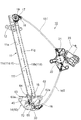
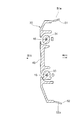
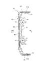
- the window regulator 10 shown in FIG.1 and FIG.2 has the guide rail 11 which is a elongate member, and illustration is abbreviate
- the guide rail 11 is arranged in a state in which the guide rail 11 is attached to the door panel of the vehicle so that the longitudinal direction thereof is substantially in the vertical direction (height direction) of the vehicle.
- the door panel to which the window regulator 10 is attached is a side door of the vehicle, and in the completed state of the vehicle, the left-right direction in FIGS. 1 and 2 is the vehicle front-rear direction.
- the window regulator 10 has a slider base (glass carrier) 14 that is supported so as to be movable up and down along the guide rail 11 in the vertical direction of the vehicle and supports a window glass (not shown).
- a slider base glass carrier
- One end of each of the pair of drive wires 15 and 16 is connected to the slider base 14.
- a pulley bracket 17 is fixed in the vicinity of the upper end of the guide rail 11 in the longitudinal direction, and a guide pulley 18 is rotatably supported on the pulley bracket 17 via a pulley support shaft 19.
- the drive wire 15 extends upward from the slider base 14 along the guide rail 11 and is supported by a wire guide groove formed on the outer peripheral surface of the guide pulley 18. As the drive wire 15 advances and retreats, the guide pulley 18 rotates about the pulley support shaft 19.
- a wire guide member 20 is provided near the lower end of the guide rail 11 in the longitudinal direction.
- the drive wire 16 extends downward from the slider base 14 along the guide rail 11 and is guided by the wire guide member 20.
- the wire guide member 20 is fixed to the guide rail 11, and the drive wire 16 is supported so as to be able to advance and retract along a wire guide groove formed in the wire guide member 20.
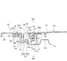
- the drive wire 15 coming out of the guide pulley 18 is inserted into a tubular outer tube 15T and wound around a drive drum 22 provided in a drum housing 21 to which the outer tube 15T is connected.
- the drive wire 16 coming out of the wire guide member 20 is inserted into a tubular outer tube 16T and wound around a drive drum 22 provided in a drum housing 21 to which the outer tube 16T is connected.
- a spiral groove around which the drive wire 15 and the drive wire 16 are wound is formed on the outer peripheral surface of the drive drum 22.
- the drive drum 22 is rotated by a motor 23.
- the drum housing 20 is fixed to a door panel (inner panel).
- the driving drum 21 rotates forward and backward by the driving force of the motor 22, one of the driving wire 15 and the driving wire 16 increases the winding amount of the driving drum 22 into the spiral groove, and the other from the spiral groove of the winding drum.
- the slider base 14 is moved along the guide rail 11 by the relationship of pulling and relaxation of the driving wire 15 and the driving wire 16. As the slider base 14 moves, the window glass moves up and down.
- the guide rail 11 protrudes toward the vehicle outer side on one side of a plate-like portion 11a having surfaces facing the vehicle inner side and the vehicle outer side (vehicle width direction).
- the support flange 11c protrudes laterally from the side wall 11b. Sliding surfaces 11d and 11e are formed on the front and back of the side wall 11b and the support flange 11c.
- the sliding surface 11d in the support flange 11c is a first sliding surface 11d-1
- the sliding surface 11e in the support flange 11c is a second sliding surface 11e-1 (see FIGS. 4 and 6).
- the first sliding surface 11d-1 is a surface facing the vehicle outer side
- the sliding surface 11e is a surface facing the vehicle inner side.
- the support flange 11c further has an edge surface 11f formed between the first sliding surface 11d-1 and the second sliding surface 11e-1.
- the edge surface 11f is located at one edge in the vehicle front-rear direction, and the edge surface 11f faces the front or rear of the vehicle with the guide rail 11 attached to the door panel.
- the guide rail 11 further has a U-shaped projecting portion 11g projecting toward the vehicle outer side with respect to the plate-like portion 11a on the side opposite to the side on which the side wall 11b and the support flange 11c are provided. have.
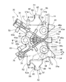
- the slider base 14 is configured by combining a sliding member 30 made of synthetic resin and a holder member 60 made of metal.
- FIG. 5 shows the sliding member 30 as a single unit.
- the sliding member 30 has a guide shoe 31 (guide portion) at the upper end in the vehicle vertical direction of the slider base 14 and a guide shoe 32 (guide portion) at the lower end.
- the guide shoe 31 includes a side wall 80 and a side wall 81 that are separated in the vehicle front-rear direction, a bottom wall 82 that connects the side wall 80 and the side wall 81, and a part of the side wall 81 on the side wall 80 side.
- a narrow groove portion 84 is formed between the side wall 80 and the convex portion 83, and the wide groove portion wider than the narrow groove portion 84 is formed between the side wall 80 and the side wall 81. 85 is formed.
- a narrowed portion 86 for partially narrowing the width of the guide shoe 31 is formed on both sides of the side wall 80 and the side wall 81.
- the narrowed portion 86 is formed in a partial region near the bottom wall 82 of the side wall 80 and the side wall 81.
- the guide shoe 31 can be elastically deformed, and in particular, is easily elastically deformed in the vehicle front-rear direction in which the distance between the side wall 80 and the side wall 81 (projection 83) is changed.
- FIG. 11 shows the guide shoe 31 in a free state.
- the guide shoe 31 in the free state has a shape in which the distance between the side wall 80 and the side wall 81 increases as the distance from the bottom wall 82 increases.
- the detailed structure of the guide shoe 32 is omitted, but it has the same configuration as the guide shoe 31 and can be elastically deformed. Parts common to the guide shoe 31 in the guide shoe 32 are denoted by the same reference numerals as the guide shoe 31.
- the sliding member 30 has a pair of wire guide grooves 33 and 34 positioned between the guide shoe 31 and the guide shoe 32 in the vehicle vertical direction.
- the wire guide grooves 33 and 34 have wire introduction ports 33 a and 34 a that open on one side of the sliding member 30, respectively, and wire end storage portions 35 and 36 are formed on the other side of the sliding member 30.
- the wire guide groove 33 is a groove portion that communicates the wire introduction port 33 a and the wire end storage portion 35.
- the wire introduction port 33 a is located above the wire end storage portion 35, and the wire guide groove 33 extends obliquely downward from the wire introduction port 33 a toward the wire end storage portion 35.
- the wire guide groove 34 is a groove portion that communicates the wire introduction port 34 a and the wire end storage portion 36.
- the wire introduction port 34 a is located below the wire end storage portion 36, and the wire guide groove 34 extends obliquely upward from the wire introduction port 34 a toward the wire end storage portion 36.
- the wire guide groove 33 and the wire guide groove 34 intersect at a crossing portion 37 in the vicinity of the wire introduction port 33a and the wire introduction port 34a.
- the wire end storage portions 35 and 36 are concave portions wider than the groove widths of the wire guide grooves 33 and 34, respectively.
- the wire end storage portion 35 is positioned on the extension of the wire guide groove 33 and protrudes obliquely downward from the side portion of the sliding member 30, and the wire end storage portion 36 is positioned on the extension of the wire guide groove 34 and slides. It protrudes obliquely upward from the side of the moving member 30.
- an insertion groove 38 that intersects the wire guide groove 33 and an insertion groove 39 that intersects the wire guide groove 34 are formed on the sliding member 30, an insertion groove 38 that intersects the wire guide groove 33 and an insertion groove 39 that intersects the wire guide groove 34 are formed.
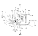
- the sliding member 30 has a grease injection portion 40 in a fan-shaped region surrounded by the wire guide grooves 33 and 34 and the insertion grooves 38 and 39 and having an intersection portion 37 as a vertex. Is formed.
- the grease injection part 40 has an injection space 55 penetrating the sliding member 30 in the vehicle interior / exterior direction, and the injection space 55 has an opening 56 on the vehicle exterior side and an opening 57 on the vehicle interior side.
- a pair of steady-state projections 41 (stabilization portions) and a grease-receiving projection 42 (grease-receiving portions) are provided in the injection space 55.
- the pair of steady rest protrusions 41 are provided at different positions in the vehicle vertical direction.
- the steady-state protrusion 41 is a cantilever-like protrusion whose base end portion is connected to a position near the opening 56 on the vehicle outside of the inner surface of the injection space 55, and is separated from the base end portion. It has an inclined shape toward the inside of the vehicle as it advances toward the tip side.
- the steady rest protrusion 41 can be elastically deformed in the vehicle interior / exterior direction with the base end as a fulcrum.
- the grease receiving protrusion 42 is located between the pair of steady rest protrusions 41 in the vehicle vertical direction.
- the grease receiving protrusion 42 is a cantilevered protrusion whose base end is connected to a position near the opening 57 on the vehicle inner side of the inner surface of the injection space 55, and is separated from the base end. It has the inclination part 42b which goes to a vehicle inner side as it advances to a front end side, and the front-end
- the steady rest protrusion 41 can be elastically deformed in the vehicle interior and exterior directions with the base end of the inclined portion 42b as a fulcrum.
- the sliding member 30 is provided with fastening seats 43 and fastening seats 44 on both sides of the vehicle in the vertical direction across the intersection 37, and the side of the insertion groove 38 and the insertion groove 39 (
- a fastening seat 45 is provided on the side opposite to the grease injection portion 40.
- the fastening seats 43, 44 and 45 are formed with insertion holes 43a, 44a and 45a penetrating in the vehicle interior / exterior direction.
- the sliding member 30 further has two fixed support portions 46 and 47 and seven elastic support portions 48, 49, 50, 51, 52, 53 and 54.
- the fixed support portion 46 is located on the side of the fastening seat 43
- the fixed support portion 47 is located on the side of the fastening seat 44, and has support surfaces 46a and 47a that face the outside of the vehicle.
- the elastic support portions 48, 49, 50, 51, 52, 53, and 54 are portions that can be elastically deformed in respective directions described later
- the fixed support portions 45 and 46 are respectively elastic support portions 48, 49, 50, 51. , 52, 53, and 54, it is a part having a fixed shape that is less likely to cause elastic deformation.
- the elastic support portion 48 is located on the side of the intersecting portion 37 and is located between the fixed support portion 45 and the fixed support portion 46 in the vehicle vertical direction.
- the elastic support portion 48 is a cantilevered protruding piece whose base end portion is connected to the vehicle outer surface of the sliding member 30, and has a contact surface 48 a facing the vehicle outer side, It can be elastically deformed in and out of the vehicle.
- FIG. 6 shows the free state of the elastic support portion 47, and the elastic support portion 48 in the free state increases the amount of protrusion to the vehicle outer side as it proceeds from the base end portion to the distal end side.
- the elastic support portion 49 is a cantilevered protruding piece that protrudes obliquely upward from the wire end storage portion 35, and has a contact surface 49 a facing the vehicle outer side.
- the elastic support portion 50 is a cantilevered protruding piece that protrudes obliquely downward from the wire end storage portion 36, and has an abutment surface 50a that faces the outside of the vehicle. Similar to the elastic support portion 48, the elastic support portions 49 and 50 can be elastically deformed in the vehicle interior and exterior directions, respectively, and the elastic support portions 49 and 50 in the free state move outward from the base end portion toward the front end side. The protruding amount is increased.
- the elastic support portion 51 is located between the guide shoe 31 and the wire end storage portion 36 in the vehicle front-rear direction
- the elastic support portion 52 is located between the guide shoe 32 and the wire end storage portion 35 in the vehicle front-rear direction.
- the elastic support portion 51 is a cantilevered protruding piece that protrudes from the upper edge of the sliding member 30 toward the inside of the vehicle, and has a contact surface 51 a that faces upward.
- the elastic support portion 52 is a cantilevered protruding piece that protrudes from the lower edge of the sliding member 30 toward the inside of the vehicle, and has a contact surface 52a that faces downward.
- the elastic support portions 51 and 52 can be elastically deformed in the vehicle vertical direction, respectively, and FIGS. 5 and 7 show the free states of the elastic support portions 51 and 52.
- the elastic support portion 51 in the free state has a curved shape in which the protruding amount of the contact surface 51a upward increases as it advances toward the front end side (inside the vehicle). ), The amount of protrusion of the downward contact surface 52a increases.
- the elastic support portions 51 and 52 gradually widen the distance in the vertical direction of the vehicle as they advance toward the front end side (the vehicle inner side).
- the elastic support portion 53 is located on the opposite side of the elastic support portion 51 (above the fastening seat 43) across the guide shoe 31 in the vehicle front-rear direction. Similar to the elastic support portion 51, the elastic support portion 53 is a cantilevered protruding piece that protrudes from the upper edge of the sliding member 30 toward the inside of the vehicle, and a contact surface 53a that faces upward (obliquely upward).
- the elastic support portion 54 is a cantilevered protruding piece that protrudes from the lower edge portion of the fixed support portion 47 toward the inside of the vehicle, and has a contact surface 54a that faces downward.
- the elastic support portions 53 and 54 can be elastically deformed in the vehicle vertical direction, respectively, and FIG.
- the elastic support portion 53 in the free state has a curved shape in which the protruding amount of the contact surface 53a upward increases as it advances toward the front end side (inside the vehicle), and the elastic support portion 54 in the free state has a front end side (inside the vehicle interior). ), The amount of protrusion of the downward contact surface 54a increases.
- the elastic support portions 53 and 54 gradually increase the distance in the vertical direction of the vehicle as they advance toward the front end side (the vehicle inner side).
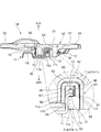
- the holder member 60 includes a plate-like cover portion 61 and glass attachment portions 62 and 63 located on both sides of the cover portion 61.
- the glass attachment portion 62 and the glass attachment portion 63 are formed with bolt insertion holes 62a and 63a into which bolts (not shown) for fastening and fixing the window glass are inserted.
- a clamping part 64 is provided on the upper end side, and a clamping part 65 is provided on the lower end side.
- the sandwiching portion 64 is a U-shaped cross-section having a pair of side walls 87 and 88 that face each other in the longitudinal direction of the vehicle and a bottom wall 89 that connects the pair of side walls 87 and 88. Yes, the inside of the vehicle opposite to the bottom wall 89 is open.
- the sandwiching part 65 has the same configuration as the sandwiching part 64, and portions common to the sandwiching part 64 in the sandwiching part 65 are denoted by the same reference numerals as the sandwiching part 64.
- a flange 66 that extends to the glass attachment portion 62 continuously to the side wall 87 of the holding portion 64, and a flange portion 67 that extends to the glass attachment portion 63 continuously to the side wall 88 of the holding portion 64. Is formed.
- a flange 68 that extends to the glass mounting portion 62 continuously from the side wall 87 of the holding portion 65 and a flange 69 that extends to the glass mounting portion 63 continuously from the side wall 88 of the holding portion 65 are formed.
- Each of the flanges 66, 67, 68 and 69 has a shape in which the periphery of the cover portion 61 is bent inward of the vehicle (see FIG. 10).
- an insertion piece 70 and an insertion piece 71 which are paired with different positions in the vehicle vertical direction.
- the insertion piece 70 and the insertion piece 71 are bifurcated protrusions that are formed by cutting and raising a part of the cover portion 61 toward the vehicle interior side, and having a groove at the tip.
- a through hole 72 is formed in the cover portion 61 by cutting and raising when the insertion piece 70 and the insertion piece 71 are formed.
- fastening holes 73, 74, and 75 are formed in the cover portion 61 at positions surrounding the through hole 72.
- the fastening holes 73, 74 and 75 are arranged in a positional relationship corresponding to the insertion holes 43 a, 44 a and 45 a of the sliding member 30.
- the driving wire 15 and the driving wire 16 are assembled to the sliding member 30.
- the end of the drive wire 15 is provided with a wire end 76 having a diameter larger than that of the drive wire 15.
- the wire end 76 is inserted into the wire end storage portion 35, and the drive wire 15 is Insert into the wire guide groove 33.
- a wire end 77 having a diameter larger than that of the drive wire 16 is provided at the end of the drive wire 16, and the wire end 77 is inserted into the wire end housing portion 36 and the drive wire 16 is inserted into the wire guide groove 34. .
- the drive wire 15 inserted into the wire guide groove 33 and the drive wire 16 inserted into the wire guide groove 34 pass through the intersection 37 and pass through the wire introduction port 33a and the wire introduction port 34a, respectively. Pulled out. As shown in FIGS. 6 and 9, the driving wire 15 and the driving wire 16 are arranged at different positions in the vehicle interior and exterior directions at the intersection 37, and the driving wire 15 and the driving wire 16 do not interfere with each other.
- the fixed support portion 46 of the sliding member 30 is drawn from the wire introduction port 33 a to the outside of the sliding member 30, and from the arrangement position of the drive wire 15 heading upward (guide pulley 18 side). Also, the shape protrudes to the side of the sliding member 30.
- the fixed support portion 47 is pulled out to the outside of the sliding member 30 from the wire introduction port 34a and protrudes to the side of the sliding member 30 from the arrangement position of the drive wire 16 directed downward (to the wire guide member 20 side). It has a shape to do.
- the holder member 60 is assembled by covering the sliding member 30 with the cover 61 from the outside with the side from which the flanges 66, 67, 68 and 69 and the insertion pieces 70, 71 protrude facing inward.
- the guide shoe 31 and the guide of the sliding member 30 are placed inside the clamping portion 64 and the clamping portion 65 provided on the holder member 60.
- the shoe 32 is inserted.
- the guide shoe 31 is inserted into the holding portion 64, thereby changing from the free state shown in FIG. 11 to the elastically deformed state shown in FIG.
- the side wall 87 and the side wall 81 are elastically deformed so as to approach each other.
- a gap in the vehicle front-rear direction exists with respect to the side wall 87 and the side wall 88 of the sandwiching portion 64 at the portion where the narrowed portion 86 is formed in the guide shoe 31.
- the guide shoe 32 is inserted into the holding portion 65, and is in an elastically deformed state in which the side wall 80 and the side wall 81 are brought close to each other.
- a gap in the vehicle front-rear direction is present with respect to the side wall 87 and the side wall 88 of the sandwiching portion 65 at the portion where the narrowed portion 86 is formed in the guide shoe 32.
- the contact surfaces 48a, 49a and 50a of the elastic support portions 48, 49 and 50 of the sliding member 30 are in contact with and supported by the cover portion 61 of the holder member 60.
- the elastic support portion 48 is elastically deformed toward the vehicle inner side in a state where the contact surface 48 a is in contact with the cover portion 61.
- the elastic support portions 49 and 50 similarly contact the contact surfaces 49 a and 50 a with the cover portion 61 while being elastically deformed toward the vehicle interior side.
- the contact surfaces 51a, 52a, 53a and 54a of the elastic support portions 51, 52, 53 and 54 are respectively flanges 66, 67, 68 and 69 of the holder member 60.
- FIG. 10 the elastic support portion 51 is brought into contact with the flange 67 while being elastically deformed downward, and the elastic support portion 52 is elastically deformed upward. Then, the contact surface 52a is brought into contact with the flange 69.
- the elastic support portion 53 causes the contact surface 53 a to contact the flange 66 in a state where it is elastically deformed downward, and the elastic support portion 54.
- the contact surface 54a is brought into contact with the flange 68 while being elastically deformed upward.
- the position of the sliding member 30 in the vehicle front-rear direction with respect to the holder member 60 is determined, and the contact surfaces 48a, 49a of the elastic support portions 48, 49 and 50 and
- the position of the sliding member 30 in the vehicle interior / exterior direction with respect to the holder member 60 is determined by the contact of the cover member 61 with the cover 50a, and the contact surfaces 51a, 52a, 53a and 54a of the elastic support portions 51, 52, 53 and 54 are flanged.
- the position of the sliding member 30 in the vertical direction of the vehicle with respect to the holder member 60 is determined by contacting with 66, 67, 68 and 69. In each of these portions, the abutting portion on the sliding member 30 side abuts in an elastically deformed state, so that variations in component accuracy and assembly accuracy between the sliding member 30 and the holder member 60 can be absorbed.
- the support surfaces 46 a and 47 a of the fixed support portions 46 and 47 of the slide member 30 face the cover portion 61 of the holder member 60 and the top of the fixed support portion 46.
- the edge portion faces the flange 66
- the lower edge portion of the fixed support portion 47 faces the flange 68 (FIG. 8).
- the insertion piece 70 is inserted into the insertion groove 38 and the insertion piece 71 is inserted into the insertion groove 39.
- Each of the insertion pieces 70, 71 has a groove at the tip, and the drive wire 15 is inserted into the groove of the insertion piece 70, and the drive wire 16 is inserted into the groove of the insertion piece 71.
- the sliding member 30 and the holder member 60 are fastened by three caulking pins 78.
- the caulking pin 78 has a head portion 78a, an intermediate diameter portion 78b, and a small diameter portion 78c.
- the small diameter portion 78c is inserted into the fastening holes 73, 74 and 75 of the holder member 60
- the intermediate diameter portion 78b is inserted into the insertion holes 43a, 44a and 45a of the sliding member 30, and the head portion 78a is inserted.
- FIG. 9 shows the fastening by the caulking pin 78 at the place of the fastening seat 45 and the fastening hole 75, but also at the place of the fastening seat 43 and the fastening hole 73 and the place of the fastening seat 44 and the fastening hole 74. Similarly, the fastening by the caulking pin 78 is performed.
- the slider base 14 configured as described above is assembled to the guide rail 11.
- the upper and lower guide shoes 31, 32, and the pair of anti-shake projections 41 and the grease receiving projections 42 located in the middle thereof can slidably contact the guide rail 11.
- the side wall 11 b is fitted into the narrow groove portion 84, and the support flange 11 c is inserted into the wide groove portion 85.
- the wide groove 85 is sized to allow the support flange 11c to be inserted with sufficient margin in the vehicle interior / exit direction.
- the support flange 11c and the side wall 11b of the guide rail 11 are in the injection space 55 of the grease injection portion 40.
- the side wall 11b and the support flange 11c of the guide rail 11 are located substantially at the center of the injection space 55 in the vehicle longitudinal direction.
- the entire support flange 11 c is located in the injection space 55, and most of the side wall 11 b is located in the injection space 55, and a part projects from the opening 57 to the vehicle interior side.
- the first sliding surface 11d-1 of the support flange 11c faces the opening 56 side of the injection space 55
- the second sliding surface 11e-1 faces the opening 57 side of the injection space 55.
- the edge surface 11f of the guide rail 11 is opposed to the inner surface of the injection space 55 with a gap.
- the pair of steady stop protrusions 41 abut against the first sliding surface 11d-1 on the vehicle outer side of the support flange 11c in an elastically deformed state.
- the support flange 11c is positioned in the wide groove portion 85 in a state where the second sliding surface 11e-1 on the vehicle inner side is brought closer to the convex portion 83 side of the guide shoe 31 (32). Accordingly, the slider base 14 has the first sliding surface 11d-1 and the second sliding surface formed by the guide shoe 31 (32) convex portion 83 and the pair of anti-rest projections 41 arranged at different positions in the vehicle vertical direction.
- the slider base 14 can be moved in the longitudinal direction of the guide rail 11 while sliding the guide shoes 31 and 32 and the pair of anti-rest projections 41 with respect to the side wall 11b and the support flange 11c.
- the grease receiving projection 42 of the slider base 14 has an inclined portion 42a on the vehicle interior side of the second sliding surface 11e-1 of the support flange 11c.
- the distal end bent part 42b is located opposite to the sliding surface 11e of the side wall 11b.
- FIG 1 and 2 show a completed state of the window regulator 10 in which the routing of the drive wire 15 and the drive wire 16 is completed and the slider base 14 is slidably supported with respect to the guide rail 11.
- the drive drum 22 in the drum housing 21 is rotated in this completed state, one of the drive wire 15 and the drive wire 16 is pulled and the other is relaxed according to the rotation direction.
- the wire ends 76 and 77 transmit force to the corresponding end surfaces of the wire end storage portions 35 and 36 (end portions on the side connected to the wire guide grooves 33 and 34).
- the insertion piece 70 is positioned on the extension of the direction of application of the load applied from the wire end 76 to the end surface of the wire end storage portion 35 when the drive wire 15 is pulled, and the insertion piece 71 is pulled by the drive wire 16. When this is done, it is located on an extension of the direction of action of the load applied from the wire end 77 to the end face of the wire end storage portion 36.
- the load in the pulling direction applied by the drive wires 15 and 16 is received by the insertion pieces 70 and 71 that are part of the metal holder member 60, thereby contributing to an improvement in the load bearing performance of the slider base 14.
- the loosened drive wires 15 and 16 are pressed in a direction away from the end surfaces of the wire ends 70 and 72 by the force of a spring (not shown) disposed in the wire end storage portions 35 and 36 to remove the slack.
- 1 and 2 show a state in which the slider base 14 is located at the lowermost part of the movable range along the longitudinal direction of the guide rail 11.
- the injection space 55 of the grease injection portion 40 in the sliding member 30 is passed through the through hole 72 of the holder member 60. Visible from the outside of the vehicle. Then, lubricating grease is injected into the injection space 55 of the grease injection portion 40. The grease is injected into the injection space 55 from the outside of the vehicle through the through hole 72 and the opening 56.
- the side wall 11 b and the support flange 11 c of the guide rail 11 are located substantially in the center in the vehicle front-rear direction (see FIGS. 6 and 9). The injected grease is stored around the side wall 11b and the support flange 11c.
- a pair of steady-state projections 41 and a grease receiving projection 42 are provided inside the injection space 55, and the arrow lines G 1 and G 2 in FIG. 6 correspond to the steady-state projection 41 and the grease receiving projection 42 in the injection space 55.
- the flow of grease along is shown schematically.
- the steady-state projection 41 has a proximal end connected to the vicinity of the opening 56 on the vehicle exterior side of the grease injecting portion 40 and is inclined toward the distal end contacting the sliding surface 11d of the support flange 11c.
- the grease (G1) flowing along the steady-state protrusion 41 is stored in a space facing the support flange 11c and the sliding surface 11d of the side wall 11b.
- the grease injected from the opening 56 is stored on the first sliding surface 11d-1 of the support flange 11c.
- the grease receiving projection 42 has a base end connected to the inner surface of the injection space 55 positioned on the vehicle inner side than the support flange 11 c and is inclined from the base end toward the vehicle inner side.
- the support flange 11c extends to the back of the sliding surface 11e (the position inside the vehicle). Therefore, the grease (G2) flowing along the grease receiving projection 42 passes between the edge surface 11f of the guide rail 11 and the inner surface of the injection space 55 and advances to the vehicle inner side than the flange 11c, and the second of the support flange 11c. It is stored in a space facing the sliding surface 11e-1 and the sliding surface 11e of the side wall 11b (hereinafter referred to as a back side storage space).
- the grease receiving projection 42 has the inclined portion 42a, the second sliding surface 11e-1 of the support flange 11c and the inclined portion 42a as it advances toward the back side (in the direction of the side wall 11b) of the back side storage space. , And the grease easily flows into the back side storage space along the inclined portion 42a.
- the grease receiving protrusion 42 has the bent end portion 42 b close to the sliding surface 11 e of the side wall 11 b, and the grease does not easily flow out from the back side storage space to the vehicle interior side.
- the injection space 55 penetrates the sliding member 30 in the vehicle interior / exterior direction. However, as shown in FIG. 5, most of the injection space 55 and the pair of steady-state projections 41 are seen from the vehicle exterior (opening 56 side). Since the grease receiving projection 42 occupies, the grease injected from the outside of the vehicle is effectively stored in the injection space 55, and there is little risk of the grease leaking out to the inside of the vehicle. Further, since the grease receiving protrusion 42 is located between the pair of steady rest protrusions 41, the grease easily flows toward the grease receiving protrusion 42, and it is easy to efficiently supply the grease to the back side storage space.
- the first sliding of the support flange 11c facing the injection-side opening 56 by injecting grease from one direction (the vehicle outer side) into the injection space 55 of the grease injection portion 40 provided in the slider base 14.
- the region along the surface 11d-1 and the region along the sliding surface 11d of the side wall 11b continuous to the first sliding surface 11d-1 but also the back-side storage space at a position that cannot be directly seen from the outside of the vehicle ( The grease can be reliably distributed to the second sliding surface 11e-1 of the support flange 11c and the space on the sliding surface 11e side of the side wall 11b.
- the grease receiving projection 42 of the slider base 14 can be elastically deformed in the vehicle interior / exterior direction, when the grease receiving projection 42 comes into contact with the support flange 11c due to a swing of the slider base 14 in the vehicle interior / exterior direction with respect to the guide rail 11 or the like.
- the grease receiving projections 42 are appropriately elastically deformed to absorb the load and keep the slider base 14 from sliding smoothly.
- the grease receiving protrusion 42 that is elastically deformable and has excellent followability with respect to the guide rail 11 is used to apply grease to the back side storage space (the sliding surface 11e and the second sliding surface 11e-1 side) of the guide rail 11. The grease can be supplied to the sliding portion with the guide rail 11 more reliably.
- the grease injection part 40 is located between the guide shoe 31 and the guide shoe 32 in the vehicle vertical direction of the slider base 14. Therefore, when the slider base 14 reaches the moving end in the vertical direction of the vehicle, excess grease that does not contribute to improving the smoothness of sliding of the slider base 14 is unlikely to remain in the vicinity of the upper end or the lower end of the guide rail 11. The grease can be supplied to the sliding portion between the guide rail 11 and the slider base 14 without waste.
- the window glass is applied from the outside of the vehicle to the glass mounting portion 62 and the glass mounting portion 63 of the holder member 60, and a glass fastening bolt is inserted through the bolt insertion holes 62a and 63a to fix the window glass. Then, the slider base 14 is brought into a state of supporting the window glass.
- the slider base 14 is configured by combining the sliding member 30 made of synthetic resin and the holder member 60 made of metal. What is a combination of such a plurality of members? Different slider bases can be applied to the present invention.
- the window regulator 10 of the embodiment is configured to inject grease from the opening 56 on the vehicle exterior side of the injection space 55
- the present invention does not limit the grease injection direction in the vehicle interior / exterior direction.
- the window regulator according to the present invention supplies grease easily and reliably to the sliding portion of the slider base with respect to both the first sliding surface and the second sliding surface of the guide rail. This contributes to improving the productivity and operability of the window regulator.
Landscapes
- Window Of Vehicle (AREA)
- Power-Operated Mechanisms For Wings (AREA)
- Engineering & Computer Science (AREA)
- Mechanical Engineering (AREA)
Abstract
A window regulator comprising a guide rail that is fixed to a vehicle door panel, and a slider base that supports a window glass and is supported so as to be slidable, in a lengthwise direction of the guide rail, along front and back sliding surfaces of the guide rail, said window regulator having, on the guide rail, a first sliding surface and a second sliding surface, sliding sections thereof facing toward one and the other of vehicle interior/exterior directions, said sliding sections being where sliding occurs with the slider base, wherein a grease injection section is provided to the slider base, said grease injection section having an injection space that opens in a vehicle interior/exterior direction and has the first sliding surface of the guide rail positioned in an interior thereof, and having a grease receiving section that is positioned facing the second sliding surface of the guide rail and receives grease injected into the injection space. Due to this grease injection section, grease can be simply and reliably supplied to the sliding sections where sliding occurs between the slider base and the first and second sliding surfaces of the guide rail.
Description
本発明は、車両のウインドガラスを昇降させるウインドレギュレータに関する。
This invention relates to the window regulator which raises / lowers the window glass of a vehicle.
車両用のウインドレギュレータとして、ウインドガラスを固定したスライダベース(ガラスキャリア)をガイドレールの長手方向に移動可能に支持し、スライダベースをワイヤによって牽引してガイドレールに対して摺動させることでウインドガラスの昇降動作を行わせるものが広く用いられている。この種のウインドレギュレータでは、ガイドレールに対してスライダベースを円滑に摺動させるために、ガイドレールとスライダベースの摺接部分にグリスが塗布される。
As a window regulator for vehicles, a slider base (glass carrier) to which a window glass is fixed is supported so as to be movable in the longitudinal direction of the guide rail, and the slider base is pulled by a wire and slid with respect to the guide rail. Those that cause the glass to move up and down are widely used. In this type of window regulator, grease is applied to the sliding contact portion between the guide rail and the slider base in order to smoothly slide the slider base relative to the guide rail.
特許文献1では、グリスを収容可能な閉鎖空間と、この閉鎖空間と外部を連通する貫通穴をスライダベースに設け、貫通穴から閉鎖空間内にグリスを注入した状態でスライダベースを摺動させてガイドレールの摺動面にグリスを塗布するようにしたウインドレギュレータが提案されている。この構成によれば、長尺部材であるガイドレールの摺動面に沿って直接にグリスを塗布する手間を省くことができる。
In Patent Document 1, a closed space that can accommodate grease and a through hole that communicates the closed space with the outside are provided in the slider base, and the slider base is slid in a state in which grease is injected into the closed space from the through hole. A window regulator has been proposed in which grease is applied to the sliding surface of the guide rail. According to this structure, the effort which apply | coats grease directly along the sliding surface of the guide rail which is a long member can be saved.
特許文献1のウインドレギュレータは、ガイドレールがスライダベースに向く側を開放したU字状の断面形状を有しており、スライダベースは、ガイドレールの開放された側に面する板状部と、該板状部から突出してガイドレールの内部に摺動可能に挿入される一対のシューを備えている。スライダベースの板状部と、一対のシューと、ガイドレールの内面とに囲まれる空間が前記の閉鎖空間であり、スライダベースの板状部に前記の貫通穴を形成している。ガイドレールの全ての摺動面(スライダベースのシューが摺接する面)がガイドレールのU字状の断面形状の内側を向く面であるため、単にスライダベースの貫通穴を通して閉鎖空間内にグリスを注入するだけで、ガイドレールの全ての摺動面に対してグリスを塗布可能な状態にできる。
The window regulator of Patent Document 1 has a U-shaped cross-sectional shape with the guide rail opening toward the slider base, and the slider base has a plate-like portion facing the open side of the guide rail, A pair of shoes projecting from the plate-like portion and slidably inserted into the guide rail are provided. A space surrounded by the plate-like portion of the slider base, the pair of shoes, and the inner surface of the guide rail is the closed space, and the through-hole is formed in the plate-like portion of the slider base. Since all the sliding surfaces of the guide rail (the surface on which the slider base shoe slides) face the inside of the U-shaped cross section of the guide rail, simply apply grease into the closed space through the through hole in the slider base. By simply injecting, grease can be applied to all sliding surfaces of the guide rail.
しかしながら、板状をなすガイドレールの表裏に摺動面を有し、該表裏の摺動面に対してスライダベースを摺接可能としたタイプのウインドレギュレータでは、特許文献1のようにスライダベースに貫通穴を形成しても、単に貫通穴からグリスを注入するだけでは、ガイドレールのうち貫通穴に向く側と反対側(裏側)の摺動面にはグリスが塗布されないという課題が生じる。そのため、貫通穴からのグリス注入とは別に、ガイドレールの裏側の摺動面にグリスを塗布する工程が必要となり、作業工数の増加やグリス塗布用の装置の複雑化が生じてしまう。
However, in a window regulator of a type having a sliding surface on the front and back of a plate-shaped guide rail and capable of sliding the slider base against the sliding surface of the front and back, the slider base as in Patent Document 1 is used. Even if the through hole is formed, simply injecting grease from the through hole causes a problem that grease is not applied to the sliding surface of the guide rail opposite to the side facing the through hole (back side). Therefore, in addition to the grease injection from the through hole, a step of applying the grease to the sliding surface on the back side of the guide rail is required, resulting in an increase in work man-hours and a complicated device for applying the grease.
本発明は以上の問題に鑑みてなされたものであり、ガイドレールの表裏の摺接面とスライダベースとの摺動部分に、簡単かつ確実にグリスを供給できるウインドレギュレータを提供することを目的とする。
The present invention has been made in view of the above problems, and an object of the present invention is to provide a window regulator that can easily and reliably supply grease to the sliding portion between the sliding contact surface of the front and back surfaces of the guide rail and the slider base. To do.
本発明は、車両ドアパネルに固定されるガイドレールと、ウインドガラスを支持してガイドレールの長手方向に摺動可能に支持されるスライダベースとを備え、ガイドレールにおけるスライダベースとの摺動部が車内外方向の一方と他方を向く第1の摺動面と第2の摺動面を有しているウインドレギュレータにおいて、スライダベースにグリス注入部を備えており、グリス注入部は、車内外方向に開口してガイドレールの第1の摺動面が内部に位置する注入空間と、ガイドレールの第2の摺動面に対向して位置し、注入空間に注入されたグリスを受けるグリス受け部とを有することを特徴としている。この構成のグリス注入部により、ガイドレールの第1の摺動面と第2の摺動面の両方にグリスを簡単かつ確実に供給することができる。
The present invention includes a guide rail that is fixed to a vehicle door panel, and a slider base that supports the window glass and is slidably supported in the longitudinal direction of the guide rail. In a window regulator having a first sliding surface and a second sliding surface facing one and the other in the vehicle interior / exterior direction, the slider base is provided with a grease injection portion, and the grease injection portion And an injection space in which the first sliding surface of the guide rail is located inside and a grease receiving portion that is positioned opposite to the second sliding surface of the guide rail and receives the grease injected into the injection space It is characterized by having. With this configuration of the grease injecting portion, it is possible to easily and reliably supply the grease to both the first sliding surface and the second sliding surface of the guide rail.
グリス受け部は、注入空間の内面から突出する弾性変形可能な突起であることが好ましい。
The grease receiving part is preferably an elastically deformable protrusion that protrudes from the inner surface of the injection space.
グリス受け部は、注入空間の内面に接続する基端部から先端側に進むにつれて車内外方向で第2の摺動面から離れる方向に進む傾斜形状を有していることが好ましい。
It is preferable that the grease receiving portion has an inclined shape that proceeds in a direction away from the second sliding surface in the vehicle interior / exterior direction as it proceeds from the proximal end portion connected to the inner surface of the injection space toward the distal end side.
ガイドレールは第1の摺動面と第2の摺動面の間に車両前後方向を向く縁を有しており、この縁が注入空間の内部に位置することで、第1の摺動面側の空間と第2の摺動面側の空間でグリスを流通させやすくなる。
The guide rail has an edge facing in the vehicle front-rear direction between the first sliding surface and the second sliding surface, and the edge is located inside the injection space, so that the first sliding surface It becomes easy to distribute the grease in the space on the side and the space on the second sliding surface side.
スライダベースは、ガイドレールの長手方向に位置を異ならせて、第1の摺動面と第2の摺動面に対して摺動可能な一対のガイド部を備えており、ガイドレールの長手方向で一対のガイド部の間にグリス注入部が位置することが好ましい。この構成により、グリス注入部に注入したグリスを、各ガイド部によってガイドレールに効率的に塗布することができる。また、ガイドレールにおけるスライダベースの摺動範囲外に余分なグリスが残留しにくくなる。
The slider base includes a pair of guide portions that are slidable with respect to the first sliding surface and the second sliding surface at different positions in the longitudinal direction of the guide rail. It is preferable that the grease injection part is located between the pair of guide parts. With this configuration, the grease injected into the grease injection portion can be efficiently applied to the guide rail by each guide portion. Further, it is difficult for excess grease to remain outside the sliding range of the slider base in the guide rail.
注入空間内に、第1の摺動面に対して摺動可能な振れ止め部を備えてもよい。さらに、注入空間内でガイドレールの長手方向に位置を異ならせて一対の振れ止め部を設け、この一対の振れ止め部の間にグリス受け部が位置するように構成すると、第2の摺動面側にグリスを導きやすくなる。
In the injection space, an anti-sway portion that is slidable with respect to the first sliding surface may be provided. Further, if a pair of steady rests are provided in the injection space in different positions in the longitudinal direction of the guide rail, and the grease receiving part is positioned between the pair of steady rests, the second sliding It becomes easy to guide grease to the surface side.
以上の本発明によれば、注入開口へのグリスの注入によってガイドレールの第1の摺動面と第2の摺動面の両方にグリスを導くことが可能な構成のグリス注入部をスライダベースに備えたので、ウインドレギュレータにおけるガイドレールとスライダベースの摺動部分への簡単かつ確実なグリスの供給を実現することができる。
According to the present invention described above, the grease injecting portion configured to be able to guide the grease to both the first sliding surface and the second sliding surface of the guide rail by injecting the grease into the injecting opening is provided with the slider base. Therefore, simple and reliable supply of grease to the guide rail and the sliding portion of the slider base in the window regulator can be realized.
図1及び図2に示すウインドレギュレータ10は、長尺部材であるガイドレール11を有し、ガイドレール11は、長手方向に位置を異ならせて設けたブラケット12,13を介して、図示を省略する車両のドアパネル(インナパネル)の内部に取り付けられる。ガイドレール11は、車両のドアパネルへの取付状態で、長手方向を概ね車両の上下方向(高さ方向)に向けて配置される。ウインドレギュレータ10が取り付けられるドアパネルは車両の側面ドアであり、車両の完成状態では、図1及び図2の左右方向が車両前後方向となる。
The window regulator 10 shown in FIG.1 and FIG.2 has the guide rail 11 which is a elongate member, and illustration is abbreviate | omitted through the brackets 12 and 13 which provided the guide rail 11 in the position which changed in the longitudinal direction. It is attached inside the door panel (inner panel) of the vehicle. The guide rail 11 is arranged in a state in which the guide rail 11 is attached to the door panel of the vehicle so that the longitudinal direction thereof is substantially in the vertical direction (height direction) of the vehicle. The door panel to which the window regulator 10 is attached is a side door of the vehicle, and in the completed state of the vehicle, the left-right direction in FIGS. 1 and 2 is the vehicle front-rear direction.
ウインドレギュレータ10は、ガイドレール11に沿って車両上下方向に昇降自在に支持され且つウインドガラス(図示略)を支持するスライダベース(ガラスキャリア)14を有している。スライダベース14には一対の駆動ワイヤ15,16のそれぞれの一端が接続されている。
The window regulator 10 has a slider base (glass carrier) 14 that is supported so as to be movable up and down along the guide rail 11 in the vertical direction of the vehicle and supports a window glass (not shown). One end of each of the pair of drive wires 15 and 16 is connected to the slider base 14.
ガイドレール11の長手方向の上端近傍にはプーリブラケット17が固定されており、このプーリブラケット17上にガイドプーリ18がプーリ支持軸19を介して回転可能に支持されている。駆動ワイヤ15は、スライダベース14からガイドレール11に沿って該ガイドレール11の上方向に延び、ガイドプーリ18の外周面上に形成したワイヤガイド溝によって支持される。駆動ワイヤ15の進退に応じて、ガイドプーリ18はプーリ支持軸19を中心とした回転を行う。
A pulley bracket 17 is fixed in the vicinity of the upper end of the guide rail 11 in the longitudinal direction, and a guide pulley 18 is rotatably supported on the pulley bracket 17 via a pulley support shaft 19. The drive wire 15 extends upward from the slider base 14 along the guide rail 11 and is supported by a wire guide groove formed on the outer peripheral surface of the guide pulley 18. As the drive wire 15 advances and retreats, the guide pulley 18 rotates about the pulley support shaft 19.
ガイドレール11の長手方向の下端近傍にはワイヤガイド部材20が設けられている。駆動ワイヤ16は、スライダベース14からガイドレール11に沿って該ガイドレール11の下方向に延びてワイヤガイド部材20に案内される。ワイヤガイド部材20は、ガイドレール11に対して固定されており、ワイヤガイド部材20に形成したワイヤガイド溝に沿って進退可能に駆動ワイヤ16が支持される。
A wire guide member 20 is provided near the lower end of the guide rail 11 in the longitudinal direction. The drive wire 16 extends downward from the slider base 14 along the guide rail 11 and is guided by the wire guide member 20. The wire guide member 20 is fixed to the guide rail 11, and the drive wire 16 is supported so as to be able to advance and retract along a wire guide groove formed in the wire guide member 20.
ガイドプーリ18から出た駆動ワイヤ15は、管状のアウタチューブ15T内に挿通され、アウタチューブ15Tが接続されるドラムハウジング21内に設けた駆動ドラム22に巻回される。ワイヤガイド部材20から出た駆動ワイヤ16は、管状のアウタチューブ16T内に挿通され、アウタチューブ16Tが接続されるドラムハウジング21内に設けた駆動ドラム22に巻回される。駆動ドラム22の外周面には、駆動ワイヤ15と駆動ワイヤ16が巻回される螺旋溝が形成されている。駆動ドラム22はモータ23によって回転駆動される。
The drive wire 15 coming out of the guide pulley 18 is inserted into a tubular outer tube 15T and wound around a drive drum 22 provided in a drum housing 21 to which the outer tube 15T is connected. The drive wire 16 coming out of the wire guide member 20 is inserted into a tubular outer tube 16T and wound around a drive drum 22 provided in a drum housing 21 to which the outer tube 16T is connected. A spiral groove around which the drive wire 15 and the drive wire 16 are wound is formed on the outer peripheral surface of the drive drum 22. The drive drum 22 is rotated by a motor 23.
ドラムハウジング20はドアパネル(インナパネル)に固定されている。モータ22の駆動力によって駆動ドラム21が正逆に回転すると、駆動ワイヤ15と駆動ワイヤ16の一方が駆動ドラム22の螺旋溝への巻回量を大きくし、他方が巻取ドラムの螺旋溝から繰り出され、駆動ワイヤ15と駆動ワイヤ16の牽引と弛緩の関係によってスライダベース14がガイドレール11に沿って移動する。スライダベース14の移動に応じてウインドガラスが昇降する。
The drum housing 20 is fixed to a door panel (inner panel). When the driving drum 21 rotates forward and backward by the driving force of the motor 22, one of the driving wire 15 and the driving wire 16 increases the winding amount of the driving drum 22 into the spiral groove, and the other from the spiral groove of the winding drum. The slider base 14 is moved along the guide rail 11 by the relationship of pulling and relaxation of the driving wire 15 and the driving wire 16. As the slider base 14 moves, the window glass moves up and down.
以下、ガイドレール11とスライダベース14の構造について詳細に説明する。図4、図6、図7、図9及び図10には、ウインドレギュレータ10を車両のドアに取り付けた状態での車外側と車内側の向きを矢線で示しており、この車外側と車内側を結ぶ方向を車内外方向とする。
Hereinafter, the structure of the guide rail 11 and the slider base 14 will be described in detail. 4, 6, 7, 9, and 10, the directions of the vehicle outer side and the vehicle inner side with the window regulator 10 attached to the vehicle door are indicated by arrows, and the vehicle outer side and the vehicle side are shown. The direction connecting the inside is the inside / outside direction.
図4、図6及び図9に示すように、ガイドレール11は、車内側と車外側に向く面を有する板状部11aの一方の側部に、車外側に向けて突出する(車幅方向に延びる)側壁11bを有し、側壁11bから側方に支持フランジ11cを突出させている。側壁11bと支持フランジ11cの表裏には摺動面11dと摺動面11eが形成されている。支持フランジ11cにおける摺動面11dを第1の摺動面11d-1とし、支持フランジ11cにおける摺動面11eを第2の摺動面11e-1とする(図4、図6参照)。第1の摺動面11d-1は車外側に向く面であり、摺動面11eは車内側を向く面である。支持フランジ11cにはさらに、第1の摺動面11d-1と第2の摺動面11e-1の間に縁面11fが形成されている。縁面11fは車両前後方向の一方の縁に位置しており、ガイドレール11をドアパネルに取り付けた状態で縁面11fが車両の前方または後方を向く。ガイドレール11はさらに、側壁11bと支持フランジ11cが設けられている側とは反対側の側部に、板状部11aに対して車外側に向けて突出するコ字状断面形状の突出部11gを有している。
As shown in FIGS. 4, 6 and 9, the guide rail 11 protrudes toward the vehicle outer side on one side of a plate-like portion 11a having surfaces facing the vehicle inner side and the vehicle outer side (vehicle width direction). The support flange 11c protrudes laterally from the side wall 11b. Sliding surfaces 11d and 11e are formed on the front and back of the side wall 11b and the support flange 11c. The sliding surface 11d in the support flange 11c is a first sliding surface 11d-1, and the sliding surface 11e in the support flange 11c is a second sliding surface 11e-1 (see FIGS. 4 and 6). The first sliding surface 11d-1 is a surface facing the vehicle outer side, and the sliding surface 11e is a surface facing the vehicle inner side. The support flange 11c further has an edge surface 11f formed between the first sliding surface 11d-1 and the second sliding surface 11e-1. The edge surface 11f is located at one edge in the vehicle front-rear direction, and the edge surface 11f faces the front or rear of the vehicle with the guide rail 11 attached to the door panel. The guide rail 11 further has a U-shaped projecting portion 11g projecting toward the vehicle outer side with respect to the plate-like portion 11a on the side opposite to the side on which the side wall 11b and the support flange 11c are provided. have.
スライダベース14は、合成樹脂製の摺動部材30と、金属製のホルダ部材60を組み合わせて構成されている。図5は摺動部材30を単体で示したものである。
The slider base 14 is configured by combining a sliding member 30 made of synthetic resin and a holder member 60 made of metal. FIG. 5 shows the sliding member 30 as a single unit.
まず、摺動部材30の構成を説明する。図5に示すように、摺動部材30は、スライダベース14の車両上下方向の上端にガイドシュー31(ガイド部)を有し、下端にガイドシュー32(ガイド部)を有する。図4及び図11に示すように、ガイドシュー31は、車両前後方向に離間する側壁80及び側壁81と、側壁80と側壁81を接続する底壁82と、側壁81の一部を側壁80側に突出させた形状の凸部83とを有しており、側壁80と凸部83の間に細溝部84が形成され、側壁80と側壁81の間に細溝部84よりも幅の広い幅広溝部85が形成される。側壁80と側壁81の両側にはガイドシュー31の幅を部分的に狭くさせる狭窄部86が形成される。狭窄部86は、側壁80と側壁81のうち底壁82に近い一部領域に形成されている。ガイドシュー31は弾性変形可能であり、特に側壁80と側壁81(凸部83)の間隔を変化させる車両前後方向に弾性変形しやすくなっている。図11に自由状態でのガイドシュー31を示している。自由状態でのガイドシュー31は、底壁82から離れるにつれて側壁80と側壁81の間隔を広くする形状になっている。ガイドシュー32については詳細構造の図示を省略しているが、ガイドシュー31と同様の構成を備えていて弾性変形可能である。ガイドシュー32においてガイドシュー31と共通する箇所については、ガイドシュー31と共通の符号を付している。
First, the configuration of the sliding member 30 will be described. As shown in FIG. 5, the sliding member 30 has a guide shoe 31 (guide portion) at the upper end in the vehicle vertical direction of the slider base 14 and a guide shoe 32 (guide portion) at the lower end. As shown in FIGS. 4 and 11, the guide shoe 31 includes a side wall 80 and a side wall 81 that are separated in the vehicle front-rear direction, a bottom wall 82 that connects the side wall 80 and the side wall 81, and a part of the side wall 81 on the side wall 80 side. And a narrow groove portion 84 is formed between the side wall 80 and the convex portion 83, and the wide groove portion wider than the narrow groove portion 84 is formed between the side wall 80 and the side wall 81. 85 is formed. On both sides of the side wall 80 and the side wall 81, a narrowed portion 86 for partially narrowing the width of the guide shoe 31 is formed. The narrowed portion 86 is formed in a partial region near the bottom wall 82 of the side wall 80 and the side wall 81. The guide shoe 31 can be elastically deformed, and in particular, is easily elastically deformed in the vehicle front-rear direction in which the distance between the side wall 80 and the side wall 81 (projection 83) is changed. FIG. 11 shows the guide shoe 31 in a free state. The guide shoe 31 in the free state has a shape in which the distance between the side wall 80 and the side wall 81 increases as the distance from the bottom wall 82 increases. The detailed structure of the guide shoe 32 is omitted, but it has the same configuration as the guide shoe 31 and can be elastically deformed. Parts common to the guide shoe 31 in the guide shoe 32 are denoted by the same reference numerals as the guide shoe 31.
図5に示すように、摺動部材30は、車両上下方向においてガイドシュー31とガイドシュー32の間に位置する一対のワイヤガイド溝33,34を有している。ワイヤガイド溝33,34はそれぞれ摺動部材30の一方の側部に開口するワイヤ導入口33a,34aを有し、摺動部材30の他方の側部にワイヤエンド収納部35,36が形成されている。ワイヤガイド溝33はワイヤ導入口33aとワイヤエンド収納部35を連通する溝部である。ワイヤ導入口33aはワイヤエンド収納部35よりも上方に位置しており、ワイヤガイド溝33はワイヤ導入口33aからワイヤエンド収納部35に向けて斜め下方に延びている。ワイヤガイド溝34はワイヤ導入口34aとワイヤエンド収納部36を連通する溝部である。ワイヤ導入口34aはワイヤエンド収納部36よりも下方に位置しており、ワイヤガイド溝34はワイヤ導入口34aからワイヤエンド収納部36に向けて斜め上方に延びている。ワイヤガイド溝33とワイヤガイド溝34は、ワイヤ導入口33aとワイヤ導入口34aの近傍の交差部37で交差している。
As shown in FIG. 5, the sliding member 30 has a pair of wire guide grooves 33 and 34 positioned between the guide shoe 31 and the guide shoe 32 in the vehicle vertical direction. The wire guide grooves 33 and 34 have wire introduction ports 33 a and 34 a that open on one side of the sliding member 30, respectively, and wire end storage portions 35 and 36 are formed on the other side of the sliding member 30. ing. The wire guide groove 33 is a groove portion that communicates the wire introduction port 33 a and the wire end storage portion 35. The wire introduction port 33 a is located above the wire end storage portion 35, and the wire guide groove 33 extends obliquely downward from the wire introduction port 33 a toward the wire end storage portion 35. The wire guide groove 34 is a groove portion that communicates the wire introduction port 34 a and the wire end storage portion 36. The wire introduction port 34 a is located below the wire end storage portion 36, and the wire guide groove 34 extends obliquely upward from the wire introduction port 34 a toward the wire end storage portion 36. The wire guide groove 33 and the wire guide groove 34 intersect at a crossing portion 37 in the vicinity of the wire introduction port 33a and the wire introduction port 34a.
ワイヤエンド収納部35,36はそれぞれワイヤガイド溝33,34の溝幅よりも幅広の凹部である。ワイヤエンド収納部35はワイヤガイド溝33の延長上に位置して摺動部材30の側部から斜め下方に突出しており、ワイヤエンド収納部36はワイヤガイド溝34の延長上に位置して摺動部材30の側部から斜め上方に突出している。また、摺動部材30上には、ワイヤガイド溝33と交差する差込溝38と、ワイヤガイド溝34と交差する差込溝39が形成されている。
The wire end storage portions 35 and 36 are concave portions wider than the groove widths of the wire guide grooves 33 and 34, respectively. The wire end storage portion 35 is positioned on the extension of the wire guide groove 33 and protrudes obliquely downward from the side portion of the sliding member 30, and the wire end storage portion 36 is positioned on the extension of the wire guide groove 34 and slides. It protrudes obliquely upward from the side of the moving member 30. On the sliding member 30, an insertion groove 38 that intersects the wire guide groove 33 and an insertion groove 39 that intersects the wire guide groove 34 are formed.
図5と図6に示すように、摺動部材30には、ワイヤガイド溝33,34と差込溝38,39に囲まれて交差部37を頂点とする扇状の領域に、グリス注入部40が形成されている。グリス注入部40は車内外方向に摺動部材30を貫通する注入空間55を有し、注入空間55は、車外側の開口56と車内側の開口57を有している。注入空間55内に一対の振れ止め突起41(振れ止め部)とグリス受け突起42(グリス受け部)が設けられている。
As shown in FIGS. 5 and 6, the sliding member 30 has a grease injection portion 40 in a fan-shaped region surrounded by the wire guide grooves 33 and 34 and the insertion grooves 38 and 39 and having an intersection portion 37 as a vertex. Is formed. The grease injection part 40 has an injection space 55 penetrating the sliding member 30 in the vehicle interior / exterior direction, and the injection space 55 has an opening 56 on the vehicle exterior side and an opening 57 on the vehicle interior side. In the injection space 55, a pair of steady-state projections 41 (stabilization portions) and a grease-receiving projection 42 (grease-receiving portions) are provided.
一対の振れ止め突起41は車両上下方向に位置を異ならせて設けられている。図6に示すように、振れ止め突起41は、注入空間55の内面のうち車外側の開口56に近い位置に基端部が接続する片持ち状の突起であり、該基端部から離れて先端側に進むにつれて車内側に向かう傾斜形状を有している。振れ止め突起41は基端部を支点として車内外方向に弾性変形可能である。
The pair of steady rest protrusions 41 are provided at different positions in the vehicle vertical direction. As shown in FIG. 6, the steady-state protrusion 41 is a cantilever-like protrusion whose base end portion is connected to a position near the opening 56 on the vehicle outside of the inner surface of the injection space 55, and is separated from the base end portion. It has an inclined shape toward the inside of the vehicle as it advances toward the tip side. The steady rest protrusion 41 can be elastically deformed in the vehicle interior / exterior direction with the base end as a fulcrum.
グリス受け突起42は、車両上下方向において一対の振れ止め突起41の間に位置している。図6に示すように、グリス受け突起42は、注入空間55の内面のうち車内側の開口57に近い位置に基端部が接続する片持ち状の突起であり、該基端部から離れて先端側に進むにつれて車内側に向かう傾斜部42bと、傾斜部42bの先端を車内側に向けて曲げた先端曲げ部42bとを有している。振れ止め突起41は、傾斜部42bの基端部を支点として車内外方向に弾性変形可能である。
The grease receiving protrusion 42 is located between the pair of steady rest protrusions 41 in the vehicle vertical direction. As shown in FIG. 6, the grease receiving protrusion 42 is a cantilevered protrusion whose base end is connected to a position near the opening 57 on the vehicle inner side of the inner surface of the injection space 55, and is separated from the base end. It has the inclination part 42b which goes to a vehicle inner side as it advances to a front end side, and the front-end | tip bending part 42b which bent the front-end | tip of the inclination part 42b toward the vehicle inner side. The steady rest protrusion 41 can be elastically deformed in the vehicle interior and exterior directions with the base end of the inclined portion 42b as a fulcrum.
図5に示すように、摺動部材30には、交差部37を挟んだ車両上下方向の両側に締結座43と締結座44が設けられ、差込溝38と差込溝39の側方(グリス注入部40と反対側の側方)に締結座45が設けられている。各締結座43,44及び45には、車内外方向に貫通する挿通穴43a,44a及び45aが形成されている。
As shown in FIG. 5, the sliding member 30 is provided with fastening seats 43 and fastening seats 44 on both sides of the vehicle in the vertical direction across the intersection 37, and the side of the insertion groove 38 and the insertion groove 39 ( A fastening seat 45 is provided on the side opposite to the grease injection portion 40. The fastening seats 43, 44 and 45 are formed with insertion holes 43a, 44a and 45a penetrating in the vehicle interior / exterior direction.
摺動部材30はさらに、2つの固定支持部46,47と、7つの弾性支持部48,49,50,51,52,53及び54を有している。固定支持部46は締結座43の側方に位置し、固定支持部47は締結座44の側方に位置しており、それぞれ車外側を向く支持面46a,47aを有している。弾性支持部48,49,50,51,52,53及び54はそれぞれ後述する各方向に弾性変形が可能な部位であり、固定支持部45,46は各弾性支持部48,49,50,51,52,53及び54に比して弾性変形を生じにくい一定形状の部位である。
The sliding member 30 further has two fixed support portions 46 and 47 and seven elastic support portions 48, 49, 50, 51, 52, 53 and 54. The fixed support portion 46 is located on the side of the fastening seat 43, and the fixed support portion 47 is located on the side of the fastening seat 44, and has support surfaces 46a and 47a that face the outside of the vehicle. The elastic support portions 48, 49, 50, 51, 52, 53, and 54 are portions that can be elastically deformed in respective directions described later, and the fixed support portions 45 and 46 are respectively elastic support portions 48, 49, 50, 51. , 52, 53, and 54, it is a part having a fixed shape that is less likely to cause elastic deformation.
図5に示すように、弾性支持部48は、交差部37の側方に位置し、車両上下方向において固定支持部45と固定支持部46の間に位置する。図6に示すように、弾性支持部48は、摺動部材30の車外側の面に基端部が接続する片持ち状の突出片であり、車外側に向く当接面48aを有し、車内外方向に弾性変形可能である。図6は弾性支持部47の自由状態を示しており、自由状態における弾性支持部48は、基端部から先端側に進むにつれて車外側への突出量を大きくしている。
As shown in FIG. 5, the elastic support portion 48 is located on the side of the intersecting portion 37 and is located between the fixed support portion 45 and the fixed support portion 46 in the vehicle vertical direction. As shown in FIG. 6, the elastic support portion 48 is a cantilevered protruding piece whose base end portion is connected to the vehicle outer surface of the sliding member 30, and has a contact surface 48 a facing the vehicle outer side, It can be elastically deformed in and out of the vehicle. FIG. 6 shows the free state of the elastic support portion 47, and the elastic support portion 48 in the free state increases the amount of protrusion to the vehicle outer side as it proceeds from the base end portion to the distal end side.
図5に示すように、弾性支持部49は、ワイヤエンド収納部35から斜め上方に向けて突出する片持ち状の突出片であり、車外側を向く当接面49aを有する。弾性支持部50は、ワイヤエンド収納部36から斜め下方に向けて突出する片持ち状の突出片であり、車外側を向く当接面50aを有する。弾性支持部48と同様に、弾性支持部49,50はそれぞれ車内外方向に弾性変形可能であり、自由状態における弾性支持部49,50は、基端部から先端側に進むにつれて車外側への突出量を大きくしている。
As shown in FIG. 5, the elastic support portion 49 is a cantilevered protruding piece that protrudes obliquely upward from the wire end storage portion 35, and has a contact surface 49 a facing the vehicle outer side. The elastic support portion 50 is a cantilevered protruding piece that protrudes obliquely downward from the wire end storage portion 36, and has an abutment surface 50a that faces the outside of the vehicle. Similar to the elastic support portion 48, the elastic support portions 49 and 50 can be elastically deformed in the vehicle interior and exterior directions, respectively, and the elastic support portions 49 and 50 in the free state move outward from the base end portion toward the front end side. The protruding amount is increased.
図5に示すように、弾性支持部51は車両前後方向においてガイドシュー31とワイヤエンド収納部36の間に位置し、弾性支持部52は車両前後方向においてガイドシュー32とワイヤエンド収納部35の間に位置している。図7に示すように、弾性支持部51は、摺動部材30の上縁部から車内側に向けて突出する片持ち状の突出片であり、上方を向く当接面51aを有する。弾性支持部52は、摺動部材30の下縁部から車内側に向けて突出する片持ち状の突出片であり、下方を向く当接面52aを有する。弾性支持部51,52はそれぞれ車両上下方向に弾性変形可能であり、図5と図7は弾性支持部51,52の自由状態を示している。自由状態における弾性支持部51は、先端側(車内側)に進むにつれて上方への当接面51aの突出量が大きくなる湾曲形状をなし、自由状態における弾性支持部52は、先端側(車内側)に進むにつれて下方への当接面52aの突出量が大きくなる湾曲形状をなしている。別言すれば、自由状態において弾性支持部51,52は、先端側(車内側)に進むにつれて徐々に車両上下方向の間隔を広くしている。
As shown in FIG. 5, the elastic support portion 51 is located between the guide shoe 31 and the wire end storage portion 36 in the vehicle front-rear direction, and the elastic support portion 52 is located between the guide shoe 32 and the wire end storage portion 35 in the vehicle front-rear direction. Located between. As shown in FIG. 7, the elastic support portion 51 is a cantilevered protruding piece that protrudes from the upper edge of the sliding member 30 toward the inside of the vehicle, and has a contact surface 51 a that faces upward. The elastic support portion 52 is a cantilevered protruding piece that protrudes from the lower edge of the sliding member 30 toward the inside of the vehicle, and has a contact surface 52a that faces downward. The elastic support portions 51 and 52 can be elastically deformed in the vehicle vertical direction, respectively, and FIGS. 5 and 7 show the free states of the elastic support portions 51 and 52. The elastic support portion 51 in the free state has a curved shape in which the protruding amount of the contact surface 51a upward increases as it advances toward the front end side (inside the vehicle). ), The amount of protrusion of the downward contact surface 52a increases. In other words, in the free state, the elastic support portions 51 and 52 gradually widen the distance in the vertical direction of the vehicle as they advance toward the front end side (the vehicle inner side).
図5に示すように、弾性支持部53は、車両前後方向においてガイドシュー31を挟んで弾性支持部51の反対側(締結座43の上方)に位置している。弾性支持部51と同様に、弾性支持部53は、摺動部材30の上縁部から車内側に向けて突出する片持ち状の突出片であり、上方(斜め上方)を向く当接面53aを有する。弾性支持部54は、固定支持部47の下縁部から車内側に向けて突出する片持ち状の突出片であり、下方を向く当接面54aを有する。弾性支持部53,54はそれぞれ車両上下方向に弾性変形可能であり、図5は弾性支持部53,54の自由状態を示している。自由状態における弾性支持部53は、先端側(車内側)に進むにつれて上方への当接面53aの突出量が大きくなる湾曲形状をなし、自由状態における弾性支持部54は、先端側(車内側)に進むにつれて下方への当接面54aの突出量が大きくなる湾曲形状をなしている。別言すれば、自由状態において弾性支持部53,54は、先端側(車内側)に進むにつれて徐々に車両上下方向の間隔を広くしている。
As shown in FIG. 5, the elastic support portion 53 is located on the opposite side of the elastic support portion 51 (above the fastening seat 43) across the guide shoe 31 in the vehicle front-rear direction. Similar to the elastic support portion 51, the elastic support portion 53 is a cantilevered protruding piece that protrudes from the upper edge of the sliding member 30 toward the inside of the vehicle, and a contact surface 53a that faces upward (obliquely upward). Have The elastic support portion 54 is a cantilevered protruding piece that protrudes from the lower edge portion of the fixed support portion 47 toward the inside of the vehicle, and has a contact surface 54a that faces downward. The elastic support portions 53 and 54 can be elastically deformed in the vehicle vertical direction, respectively, and FIG. 5 shows a free state of the elastic support portions 53 and 54. The elastic support portion 53 in the free state has a curved shape in which the protruding amount of the contact surface 53a upward increases as it advances toward the front end side (inside the vehicle), and the elastic support portion 54 in the free state has a front end side (inside the vehicle interior). ), The amount of protrusion of the downward contact surface 54a increases. In other words, in the free state, the elastic support portions 53 and 54 gradually increase the distance in the vertical direction of the vehicle as they advance toward the front end side (the vehicle inner side).
続いて、ホルダ部材60の構成を説明する。図3に示すように、ホルダ部材60は、板状のカバー部61と、カバー部61の両側に位置するガラス取付部62,63とを有する。ガラス取付部62とガラス取付部63には、ウインドガラスを締結固定するボルト(図示略)が挿入されるボルト挿通穴62a,63aが形成されている。
Subsequently, the configuration of the holder member 60 will be described. As shown in FIG. 3, the holder member 60 includes a plate-like cover portion 61 and glass attachment portions 62 and 63 located on both sides of the cover portion 61. The glass attachment portion 62 and the glass attachment portion 63 are formed with bolt insertion holes 62a and 63a into which bolts (not shown) for fastening and fixing the window glass are inserted.
カバー部61の車両前後方向の中央付近には、上端側に挟持部64が設けられ、下端側に挟持部65が設けられている。図4に示すように、挟持部64は、車両前後方向に離間して対向する一対の側壁87,88と、該一対の側壁87,88を接続する底壁89を有するコ字状断面部であり、底壁89と反対の車内側が開放されている。挟持部65は挟持部64と同様の構成を備えており、挟持部65において挟持部64と共通する箇所については、挟持部64と共通の符号を付している。
Near the center of the cover 61 in the vehicle front-rear direction, a clamping part 64 is provided on the upper end side, and a clamping part 65 is provided on the lower end side. As shown in FIG. 4, the sandwiching portion 64 is a U-shaped cross-section having a pair of side walls 87 and 88 that face each other in the longitudinal direction of the vehicle and a bottom wall 89 that connects the pair of side walls 87 and 88. Yes, the inside of the vehicle opposite to the bottom wall 89 is open. The sandwiching part 65 has the same configuration as the sandwiching part 64, and portions common to the sandwiching part 64 in the sandwiching part 65 are denoted by the same reference numerals as the sandwiching part 64.
ホルダ部材60の上縁部には、挟持部64の側壁87に連続してガラス取付部62まで延びるフランジ66と、挟持部64の側壁88に連続してガラス取付部63まで延びるフランジ部67が形成されている。ホルダ部材60の下縁部には、挟持部65の側壁87に連続してガラス取付部62まで延びるフランジ68と、挟持部65の側壁88に連続してガラス取付部63まで延びるフランジ69が形成されている。フランジ66,67,68及び69はいずれも、カバー部61の周縁を車内側に曲げた形状をなしている(図10参照)。
At the upper edge portion of the holder member 60, there are a flange 66 that extends to the glass attachment portion 62 continuously to the side wall 87 of the holding portion 64, and a flange portion 67 that extends to the glass attachment portion 63 continuously to the side wall 88 of the holding portion 64. Is formed. At the lower edge of the holder member 60, a flange 68 that extends to the glass mounting portion 62 continuously from the side wall 87 of the holding portion 65 and a flange 69 that extends to the glass mounting portion 63 continuously from the side wall 88 of the holding portion 65 are formed. Has been. Each of the flanges 66, 67, 68 and 69 has a shape in which the periphery of the cover portion 61 is bent inward of the vehicle (see FIG. 10).
カバー部61の中央付近には、車両上下方向に位置を異ならせて対をなす差込片70と差込片71が形成されている。差込片70と差込片71は、カバー部61の一部を車内側に向けて切り起こして形成され、その先端部分に溝部を有する二股状の突出部である。カバー部61には、差込片70と差込片71を形成する際の切り起こしによって貫通穴72が形成されている。
Near the center of the cover 61, there are formed an insertion piece 70 and an insertion piece 71 which are paired with different positions in the vehicle vertical direction. The insertion piece 70 and the insertion piece 71 are bifurcated protrusions that are formed by cutting and raising a part of the cover portion 61 toward the vehicle interior side, and having a groove at the tip. A through hole 72 is formed in the cover portion 61 by cutting and raising when the insertion piece 70 and the insertion piece 71 are formed.
カバー部61にはさらに、貫通穴72を囲む位置に3つの締結穴73,74及び75が形成されている。締結穴73,74及び75は、摺動部材30の挿通穴43a,44a及び45aに対応する位置関係で配されている。
Further, three fastening holes 73, 74, and 75 are formed in the cover portion 61 at positions surrounding the through hole 72. The fastening holes 73, 74 and 75 are arranged in a positional relationship corresponding to the insertion holes 43 a, 44 a and 45 a of the sliding member 30.
摺動部材30とホルダ部材60を組み合わせる前に、駆動ワイヤ15と駆動ワイヤ16が摺動部材30に組み付けられる。図5に示すように、駆動ワイヤ15の端部には駆動ワイヤ15よりも大径のワイヤエンド76が設けられており、ワイヤエンド76をワイヤエンド収納部35に挿入すると共に、駆動ワイヤ15をワイヤガイド溝33に挿入する。駆動ワイヤ16の端部には駆動ワイヤ16よりも大径のワイヤエンド77が設けられており、ワイヤエンド77をワイヤエンド収納部36に挿入すると共に、駆動ワイヤ16をワイヤガイド溝34に挿入する。ワイヤエンド収納部35とワイヤエンド収納部36の内部にはそれぞれ、ワイヤエンド76とワイヤエンド77を牽引方向(ワイヤガイド溝33,34と反対方向)に付勢するバネ(図示略)が挿入される。ワイヤガイド溝33内に挿入された駆動ワイヤ15と、ワイヤガイド溝34内に挿入された駆動ワイヤ16はそれぞれ、交差部37を通り、ワイヤ導入口33aとワイヤ導入口34aを通して摺動部材30の外側に引き出される。図6及び図9に示すように、交差部37において駆動ワイヤ15と駆動ワイヤ16は車内外方向に位置を異ならせて配策されており、駆動ワイヤ15と駆動ワイヤ16は互いに干渉しない。
Before combining the sliding member 30 and the holder member 60, the driving wire 15 and the driving wire 16 are assembled to the sliding member 30. As shown in FIG. 5, the end of the drive wire 15 is provided with a wire end 76 having a diameter larger than that of the drive wire 15. The wire end 76 is inserted into the wire end storage portion 35, and the drive wire 15 is Insert into the wire guide groove 33. A wire end 77 having a diameter larger than that of the drive wire 16 is provided at the end of the drive wire 16, and the wire end 77 is inserted into the wire end housing portion 36 and the drive wire 16 is inserted into the wire guide groove 34. . Springs (not shown) for urging the wire end 76 and the wire end 77 in the pulling direction (the direction opposite to the wire guide grooves 33 and 34) are inserted into the wire end storage portion 35 and the wire end storage portion 36, respectively. The The drive wire 15 inserted into the wire guide groove 33 and the drive wire 16 inserted into the wire guide groove 34 pass through the intersection 37 and pass through the wire introduction port 33a and the wire introduction port 34a, respectively. Pulled out. As shown in FIGS. 6 and 9, the driving wire 15 and the driving wire 16 are arranged at different positions in the vehicle interior and exterior directions at the intersection 37, and the driving wire 15 and the driving wire 16 do not interfere with each other.
図5に示すように、摺動部材30の固定支持部46は、ワイヤ導入口33aから摺動部材30の外側に引き出されて上方(ガイドプーリ18側)に向かう駆動ワイヤ15の配策位置よりも、摺動部材30の側方に突出する形状になっている。固定支持部47は、ワイヤ導入口34aから摺動部材30の外側に引き出されて下方(ワイヤガイド部材20側)に向かう駆動ワイヤ16の配策位置よりも、摺動部材30の側方に突出する形状になっている。
As shown in FIG. 5, the fixed support portion 46 of the sliding member 30 is drawn from the wire introduction port 33 a to the outside of the sliding member 30, and from the arrangement position of the drive wire 15 heading upward (guide pulley 18 side). Also, the shape protrudes to the side of the sliding member 30. The fixed support portion 47 is pulled out to the outside of the sliding member 30 from the wire introduction port 34a and protrudes to the side of the sliding member 30 from the arrangement position of the drive wire 16 directed downward (to the wire guide member 20 side). It has a shape to do.
ホルダ部材60は、フランジ66,67,68及び69や差込片70,71が突出する側を車内側に向けて、摺動部材30に対してカバー部61を車外側から被せて組み付けられる。図4や図8に示すように、ホルダ部材60を摺動部材30に組み付けた状態では、ホルダ部材60に設けた挟持部64と挟持部65の内部に摺動部材30のガイドシュー31とガイドシュー32が挿入される。ガイドシュー31は、挟持部64内に挿入されることで、図11に示す自由状態から図4に示す弾性変形状態に変化する。具体的には、挟持部64の側壁87と側壁88の対向する面の間隔よりも、自由状態にあるガイドシュー31の側壁80から側壁81までの最大幅の方が大きいため、側壁87と側壁88によって車両前後方向の広がりが規制された側壁80と側壁81が互いに接近する状態に弾性変形される。このとき、図4に示すように、ガイドシュー31のうち狭窄部86の形成箇所では、挟持部64の側壁87と側壁88に対して車両前後方向の隙間が存在している。ガイドシュー31と同様に、ガイドシュー32は、挟持部65内に挿入されることで、側壁80と側壁81を互いに接近させる弾性変形状態になる。ガイドシュー32のうち狭窄部86の形成箇所では、挟持部65の側壁87と側壁88に対して車両前後方向の隙間が存在している。
The holder member 60 is assembled by covering the sliding member 30 with the cover 61 from the outside with the side from which the flanges 66, 67, 68 and 69 and the insertion pieces 70, 71 protrude facing inward. As shown in FIGS. 4 and 8, when the holder member 60 is assembled to the sliding member 30, the guide shoe 31 and the guide of the sliding member 30 are placed inside the clamping portion 64 and the clamping portion 65 provided on the holder member 60. The shoe 32 is inserted. The guide shoe 31 is inserted into the holding portion 64, thereby changing from the free state shown in FIG. 11 to the elastically deformed state shown in FIG. Specifically, since the maximum width from the side wall 80 to the side wall 81 of the guide shoe 31 in the free state is larger than the distance between the opposing surfaces of the side wall 87 and the side wall 88 of the sandwiching portion 64, the side wall 87 and the side wall The side wall 80 and the side wall 81, whose spread in the vehicle front-rear direction is regulated by 88, are elastically deformed so as to approach each other. At this time, as shown in FIG. 4, a gap in the vehicle front-rear direction exists with respect to the side wall 87 and the side wall 88 of the sandwiching portion 64 at the portion where the narrowed portion 86 is formed in the guide shoe 31. Similar to the guide shoe 31, the guide shoe 32 is inserted into the holding portion 65, and is in an elastically deformed state in which the side wall 80 and the side wall 81 are brought close to each other. A gap in the vehicle front-rear direction is present with respect to the side wall 87 and the side wall 88 of the sandwiching portion 65 at the portion where the narrowed portion 86 is formed in the guide shoe 32.
ホルダ部材60を摺動部材30に組み付けると、摺動部材30の弾性支持部48,49及び50の当接面48a,49a及び50aが、ホルダ部材60のカバー部61に当接して支持される。図9に示すように、弾性支持部48は、当接面48aをカバー部61に当接させた状態で車内側に向けて弾性変形している。図9には表れていないが、弾性支持部49,50も同様に、車内側に向けて弾性変形された状態で当接面49a,50aをカバー部61に当接させる。
When the holder member 60 is assembled to the sliding member 30, the contact surfaces 48a, 49a and 50a of the elastic support portions 48, 49 and 50 of the sliding member 30 are in contact with and supported by the cover portion 61 of the holder member 60. . As shown in FIG. 9, the elastic support portion 48 is elastically deformed toward the vehicle inner side in a state where the contact surface 48 a is in contact with the cover portion 61. Although not shown in FIG. 9, the elastic support portions 49 and 50 similarly contact the contact surfaces 49 a and 50 a with the cover portion 61 while being elastically deformed toward the vehicle interior side.
さらに、ホルダ部材60を摺動部材30に組み付けると、弾性支持部51,52,53及び54の当接面51a,52a,53a及び54aがそれぞれ、ホルダ部材60のフランジ66,67,68及び69に当接して支持される(図8)。図10に示すように、弾性支持部51は、下方に向けて弾性変形された状態で当接面51aをフランジ67に当接させ、弾性支持部52は、上方に向けて弾性変形された状態で当接面52aをフランジ69に当接させる。図10には表れていないが、弾性支持部53は、第性支持部51と同様に、下方に向けて弾性変形された状態で当接面53aをフランジ66に当接させ、弾性支持部54は、弾性支持部52と同様に、上方に向けて弾性変形された状態で当接面54aをフランジ68に当接させる。
Further, when the holder member 60 is assembled to the sliding member 30, the contact surfaces 51a, 52a, 53a and 54a of the elastic support portions 51, 52, 53 and 54 are respectively flanges 66, 67, 68 and 69 of the holder member 60. (FIG. 8). As shown in FIG. 10, the elastic support portion 51 is brought into contact with the flange 67 while being elastically deformed downward, and the elastic support portion 52 is elastically deformed upward. Then, the contact surface 52a is brought into contact with the flange 69. Although not shown in FIG. 10, like the first support portion 51, the elastic support portion 53 causes the contact surface 53 a to contact the flange 66 in a state where it is elastically deformed downward, and the elastic support portion 54. Like the elastic support portion 52, the contact surface 54a is brought into contact with the flange 68 while being elastically deformed upward.
ガイドシュー31,32が挟持部64,65によって挟持されることでホルダ部材60に対する摺動部材30の車両前後方向の位置が定まり、弾性支持部48,49及び50の当接面48a,49a及び50aがカバー部61に当接することでホルダ部材60に対する摺動部材30の車内外方向の位置が定まり、弾性支持部51,52,53及び54の当接面51a,52a,53a及び54aがフランジ66,67,68及び69に当接することでホルダ部材60に対する摺動部材30の車両上下方向の位置が定まる。これらの各部分では、摺動部材30側の当接部分が弾性変形した状態で当接することにより、摺動部材30とホルダ部材60の部品精度や組付精度のばらつきを吸収することができる。
When the guide shoes 31 and 32 are clamped by the clamping portions 64 and 65, the position of the sliding member 30 in the vehicle front-rear direction with respect to the holder member 60 is determined, and the contact surfaces 48a, 49a of the elastic support portions 48, 49 and 50 and The position of the sliding member 30 in the vehicle interior / exterior direction with respect to the holder member 60 is determined by the contact of the cover member 61 with the cover 50a, and the contact surfaces 51a, 52a, 53a and 54a of the elastic support portions 51, 52, 53 and 54 are flanged. The position of the sliding member 30 in the vertical direction of the vehicle with respect to the holder member 60 is determined by contacting with 66, 67, 68 and 69. In each of these portions, the abutting portion on the sliding member 30 side abuts in an elastically deformed state, so that variations in component accuracy and assembly accuracy between the sliding member 30 and the holder member 60 can be absorbed.
また、ホルダ部材60を摺動部材30に組み付けると、摺動部材30の固定支持部46,47の支持面46a,47aがホルダ部材60のカバー部61に対向すると共に、固定支持部46の上縁部がフランジ66に対向し、固定支持部47の下縁部がフランジ68に対向する(図8)。ホルダ部材60に対して摺動部材30を車両上下方向や車内外方向に大きく傾かせようとする荷重が加わったときには、固定支持部46と固定支持部47がホルダ部材60側の対向部位に当接して荷重に耐えることができる。
Further, when the holder member 60 is assembled to the sliding member 30, the support surfaces 46 a and 47 a of the fixed support portions 46 and 47 of the slide member 30 face the cover portion 61 of the holder member 60 and the top of the fixed support portion 46. The edge portion faces the flange 66, and the lower edge portion of the fixed support portion 47 faces the flange 68 (FIG. 8). When a load is applied to the holder member 60 so as to greatly tilt the sliding member 30 in the vehicle up-down direction or the vehicle interior / exit direction, the fixed support portion 46 and the fixed support portion 47 contact the opposing portion on the holder member 60 side. Can withstand the load in contact.
また、ホルダ部材60を摺動部材30に組み付けると、差込片70が差込溝38に挿入され、差込片71が差込溝39に挿入される。差込片70,71はいずれも先端部分に溝部を有しており、差込片70の溝部内に駆動ワイヤ15が挿通され、差込片71の溝部内に駆動ワイヤ16が挿通される。
Further, when the holder member 60 is assembled to the sliding member 30, the insertion piece 70 is inserted into the insertion groove 38 and the insertion piece 71 is inserted into the insertion groove 39. Each of the insertion pieces 70, 71 has a groove at the tip, and the drive wire 15 is inserted into the groove of the insertion piece 70, and the drive wire 16 is inserted into the groove of the insertion piece 71.
摺動部材30とホルダ部材60は、3つのかしめピン78によって締結される。図9に示すように、かしめピン78は、頭部78aと中間径部78bと小径部78cを有している。各かしめピン78は、小径部78cをホルダ部材60の締結穴73,74及び75に挿入し、中間径部78bを摺動部材30の挿通穴43a,44a及び45aに挿入し、頭部78aを摺動部材30の締結座43,44及び45に当接させた状態で、小径部78cの先端をかしめてかしめ部78dを形成することで、摺動部材30とホルダ部材60を締結させる(図9参照)。図9は締結座45と締結穴75の箇所でのかしめピン78による締結を示しているが、締結座43と締結穴73の箇所と、締結座44と締結穴74の箇所でも、図9と同様にかしめピン78による締結が行われる。
The sliding member 30 and the holder member 60 are fastened by three caulking pins 78. As shown in FIG. 9, the caulking pin 78 has a head portion 78a, an intermediate diameter portion 78b, and a small diameter portion 78c. In each caulking pin 78, the small diameter portion 78c is inserted into the fastening holes 73, 74 and 75 of the holder member 60, the intermediate diameter portion 78b is inserted into the insertion holes 43a, 44a and 45a of the sliding member 30, and the head portion 78a is inserted. The sliding member 30 and the holder member 60 are fastened by forming the caulking portion 78d by caulking the tip of the small diameter portion 78c in a state where the sliding seat 30 is in contact with the fastening seats 43, 44 and 45 (see FIG. 9). FIG. 9 shows the fastening by the caulking pin 78 at the place of the fastening seat 45 and the fastening hole 75, but also at the place of the fastening seat 43 and the fastening hole 73 and the place of the fastening seat 44 and the fastening hole 74. Similarly, the fastening by the caulking pin 78 is performed.
以上のように構成したスライダベース14をガイドレール11に組み付ける。スライダベース14のうち、上下のガイドシュー31,32と、その中間に位置する一対の振れ止め突起41及びグリス受け突起42は、ガイドレール11に対して摺動可能に当接することができる。図4に示すように、ガイドシュー31(32)は、細溝部84に側壁11bを嵌合させ、幅広溝部85内に支持フランジ11cを挿入させる。細溝部84の両側を構成する側壁80と凸部83によって側壁11bの摺動面11d,11eを挟持することで、ガイドレール11に対するスライダベース14の車両前後方向の位置が定まる。幅広溝部85は、支持フランジ11cを車内外方向に余裕をもって挿入させるサイズになっている。
The slider base 14 configured as described above is assembled to the guide rail 11. Of the slider base 14, the upper and lower guide shoes 31, 32, and the pair of anti-shake projections 41 and the grease receiving projections 42 located in the middle thereof can slidably contact the guide rail 11. As shown in FIG. 4, in the guide shoe 31 (32), the side wall 11 b is fitted into the narrow groove portion 84, and the support flange 11 c is inserted into the wide groove portion 85. By sandwiching the sliding surfaces 11d and 11e of the side wall 11b by the side wall 80 and the convex part 83 constituting both sides of the narrow groove portion 84, the position of the slider base 14 in the vehicle front-rear direction with respect to the guide rail 11 is determined. The wide groove 85 is sized to allow the support flange 11c to be inserted with sufficient margin in the vehicle interior / exit direction.
図6と図9に示すように、スライダベース14をガイドレール11に対して摺動可能に支持させた状態で、ガイドレール11の支持フランジ11cと側壁11bがグリス注入部40の注入空間55内に位置する。より詳しくは、車両前後方向において、注入空間55の略中央にガイドレール11の側壁11bと支持フランジ11cが位置する。車内外方向では、支持フランジ11cの全体が注入空間55内に位置し、側壁11bは、大部分が注入空間55内に位置して一部が開口57から車内側に突出する。そして、支持フランジ11cの第1の摺動面11d-1が注入空間55の開口56側を向き、第2の摺動面11e-1が注入空間55の開口57側を向く。ガイドレール11の縁面11fは、注入空間55の内面に対して間隔を空けて対向する。
As shown in FIGS. 6 and 9, in the state where the slider base 14 is slidably supported with respect to the guide rail 11, the support flange 11c and the side wall 11b of the guide rail 11 are in the injection space 55 of the grease injection portion 40. Located in. More specifically, the side wall 11b and the support flange 11c of the guide rail 11 are located substantially at the center of the injection space 55 in the vehicle longitudinal direction. In the vehicle interior / exterior direction, the entire support flange 11 c is located in the injection space 55, and most of the side wall 11 b is located in the injection space 55, and a part projects from the opening 57 to the vehicle interior side. The first sliding surface 11d-1 of the support flange 11c faces the opening 56 side of the injection space 55, and the second sliding surface 11e-1 faces the opening 57 side of the injection space 55. The edge surface 11f of the guide rail 11 is opposed to the inner surface of the injection space 55 with a gap.
図4や図6に示すように、注入空間55内で、支持フランジ11cの車外側の第1の摺動面11d-1に対して一対の振れ止め突起41が弾性変形した状態で当接しており、支持フランジ11cは、車内側の第2の摺動面11e-1がガイドシュー31(32)の凸部83側に寄せられた状態で幅広溝部85内に位置する。従って、スライダベース14は、車両上下方向に位置を異ならせて配したガイドシュー31(32)凸部83と一対の振れ止め突起41とよって第1の摺動面11d-1と第2の摺動面11e-1を挟むことによって、支持フランジ11cに対する車内外方向の位置が定まる。そして、スライダベース14は、側壁11bと支持フランジ11cに対してガイドシュー31,32と一対の振れ止め突起41を摺動させながら、ガイドレール11の長手方向に移動することができる。
As shown in FIG. 4 and FIG. 6, in the injection space 55, the pair of steady stop protrusions 41 abut against the first sliding surface 11d-1 on the vehicle outer side of the support flange 11c in an elastically deformed state. The support flange 11c is positioned in the wide groove portion 85 in a state where the second sliding surface 11e-1 on the vehicle inner side is brought closer to the convex portion 83 side of the guide shoe 31 (32). Accordingly, the slider base 14 has the first sliding surface 11d-1 and the second sliding surface formed by the guide shoe 31 (32) convex portion 83 and the pair of anti-rest projections 41 arranged at different positions in the vehicle vertical direction. By sandwiching the moving surface 11e-1, the position of the inside and outside of the vehicle with respect to the support flange 11c is determined. The slider base 14 can be moved in the longitudinal direction of the guide rail 11 while sliding the guide shoes 31 and 32 and the pair of anti-rest projections 41 with respect to the side wall 11b and the support flange 11c.
図6に示すように、スライダベース14をガイドレール11に組み付けた状態で、スライダベース14のグリス受け突起42は、傾斜部42aが支持フランジ11cの第2の摺動面11e-1の車内側に対向して位置し、先端曲げ部42bが側壁11bの摺動面11eに対向して位置する。傾斜部42aと支持フランジ11cの第2の摺動面11e-1との間には車内外方向に所定のスペースがあり、先端曲げ部42bは側壁11bの摺動面11eに近接して位置する。
As shown in FIG. 6, with the slider base 14 assembled to the guide rail 11, the grease receiving projection 42 of the slider base 14 has an inclined portion 42a on the vehicle interior side of the second sliding surface 11e-1 of the support flange 11c. The distal end bent part 42b is located opposite to the sliding surface 11e of the side wall 11b. There is a predetermined space between the inclined portion 42a and the second sliding surface 11e-1 of the support flange 11c in the vehicle interior / exterior direction, and the tip bending portion 42b is located close to the sliding surface 11e of the side wall 11b. .
図1と図2は、駆動ワイヤ15と駆動ワイヤ16の配索が完了し、かつガイドレール11に対してスライダベース14を摺動可能に支持させたウインドレギュレータ10の完成状態である。この完成状態でドラムハウジング21内の駆動ドラム22を回転させると、その回転方向に応じて駆動ワイヤ15と駆動ワイヤ16の一方が牽引され他方が弛緩される。牽引された側の駆動ワイヤ15,16では、ワイヤエンド76,77が対応するワイヤエンド収納部35,36の端面(ワイヤガイド溝33,34に接続する側の端部)に力を伝える。ワイヤエンド76,77はワイヤエンド収納部35,36の端面との当接によってスライダベース14に対するそれ以上の移動(駆動ドラム22側への移動)が規制されるため、牽引された側の駆動ワイヤ15,16からスライダベース14に対して、ガイドレール11の長手方向へ移動させる力が作用する。差込片70は、駆動ワイヤ15が牽引されたときにワイヤエンド76からワイヤエンド収納部35の端面に加わる荷重の作用方向の延長上に位置し、差込片71は、駆動ワイヤ16が牽引されたときにワイヤエンド77からワイヤエンド収納部36の端面に加わる荷重の作用方向の延長上に位置している。各駆動ワイヤ15,16によって付与される牽引方向の荷重を金属製のホルダ部材60の一部である差込片70,71で受けることにより、スライダベース14の耐荷重性能の向上に寄与する。弛緩した側の駆動ワイヤ15,16は、ワイヤエンド収納部35,36内に配したバネ(図示略)の力によってワイヤエンド70,72の端面から離れる方向に押圧されて弛みが除去される。図1と図2は、ガイドレール11の長手方向に沿う可動範囲の最も下方にスライダベース14が位置する状態を示している。
1 and 2 show a completed state of the window regulator 10 in which the routing of the drive wire 15 and the drive wire 16 is completed and the slider base 14 is slidably supported with respect to the guide rail 11. When the drive drum 22 in the drum housing 21 is rotated in this completed state, one of the drive wire 15 and the drive wire 16 is pulled and the other is relaxed according to the rotation direction. In the driven wires 15 and 16 on the pulled side, the wire ends 76 and 77 transmit force to the corresponding end surfaces of the wire end storage portions 35 and 36 (end portions on the side connected to the wire guide grooves 33 and 34). Since the wire ends 76 and 77 are restricted from further movement with respect to the slider base 14 (moving toward the drive drum 22) by contact with the end surfaces of the wire end storage portions 35 and 36, the drive wires on the pulled side are controlled. A force for moving the guide rail 11 in the longitudinal direction acts on the slider base 14 from 15 and 16. The insertion piece 70 is positioned on the extension of the direction of application of the load applied from the wire end 76 to the end surface of the wire end storage portion 35 when the drive wire 15 is pulled, and the insertion piece 71 is pulled by the drive wire 16. When this is done, it is located on an extension of the direction of action of the load applied from the wire end 77 to the end face of the wire end storage portion 36. The load in the pulling direction applied by the drive wires 15 and 16 is received by the insertion pieces 70 and 71 that are part of the metal holder member 60, thereby contributing to an improvement in the load bearing performance of the slider base 14. The loosened drive wires 15 and 16 are pressed in a direction away from the end surfaces of the wire ends 70 and 72 by the force of a spring (not shown) disposed in the wire end storage portions 35 and 36 to remove the slack. 1 and 2 show a state in which the slider base 14 is located at the lowermost part of the movable range along the longitudinal direction of the guide rail 11.
図3に示すように、スライダベース14をガイドレール11に対して摺動可能に支持させた状態で、ホルダ部材60の貫通穴72を通して、摺動部材30におけるグリス注入部40の注入空間55を車外側から視認することができる。そして、グリス注入部40の注入空間55内へ潤滑用のグリスを注入する。注入空間55へのグリスの注入は、貫通穴72と開口56を通して車外側から行う。上述のように、注入空間55内には、車両前後方向における略中央にガイドレール11の側壁11bと支持フランジ11cが位置しており(図6及び図9参照)、注入空間55内40内に注入したグリスは側壁11bと支持フランジ11cの周りに貯留される。
As shown in FIG. 3, in the state where the slider base 14 is slidably supported with respect to the guide rail 11, the injection space 55 of the grease injection portion 40 in the sliding member 30 is passed through the through hole 72 of the holder member 60. Visible from the outside of the vehicle. Then, lubricating grease is injected into the injection space 55 of the grease injection portion 40. The grease is injected into the injection space 55 from the outside of the vehicle through the through hole 72 and the opening 56. As described above, in the injection space 55, the side wall 11 b and the support flange 11 c of the guide rail 11 are located substantially in the center in the vehicle front-rear direction (see FIGS. 6 and 9). The injected grease is stored around the side wall 11b and the support flange 11c.
注入空間55の内部には一対の振れ止め突起41とグリス受け突起42が設けられており、図6の矢線G1,G2は、注入空間55内での振れ止め突起41とグリス受け突起42に沿ったグリスの流れを模式的に示したものである。図6に示すように、振れ止め突起41は、グリス注入部40の車外側の開口56付近に基端部が接続し、支持フランジ11cの摺動面11dに当接する先端部に向けて傾斜しながら延設されているため、振れ止め突起41に沿って流れるグリス(G1)は、支持フランジ11cと側壁11bの摺動面11dに臨む空間に貯留される。また、各振れ止め突起41の間のスペースでは、開口56から注入されたグリスが支持フランジ11cの第1の摺動面11d-1上に貯留される。
A pair of steady-state projections 41 and a grease receiving projection 42 are provided inside the injection space 55, and the arrow lines G 1 and G 2 in FIG. 6 correspond to the steady-state projection 41 and the grease receiving projection 42 in the injection space 55. The flow of grease along is shown schematically. As shown in FIG. 6, the steady-state projection 41 has a proximal end connected to the vicinity of the opening 56 on the vehicle exterior side of the grease injecting portion 40 and is inclined toward the distal end contacting the sliding surface 11d of the support flange 11c. However, the grease (G1) flowing along the steady-state protrusion 41 is stored in a space facing the support flange 11c and the sliding surface 11d of the side wall 11b. Further, in the space between the steady rest projections 41, the grease injected from the opening 56 is stored on the first sliding surface 11d-1 of the support flange 11c.
図6に示すように、グリス受け突起42は、注入空間55の内面に接続する基端部が支持フランジ11cよりも車内側に位置し、かつ該基端部から車内側に向けて傾斜しながら支持フランジ11cの摺動面11eの背後(車内側の位置)まで延設されている。そのため、グリス受け突起42に沿って流れるグリス(G2)は、ガイドレール11の縁面11fと注入空間55の内面の間を通ってフランジ11cよりも車内側に進み、支持フランジ11cの第2の摺動面11e-1と側壁11bの摺動面11eに臨む空間(以下、裏側貯留空間と呼ぶ)に貯留される。特に、グリス受け突起42が傾斜部42aを有していることで、裏側貯留空間の奥側(側壁11bの方向)に進むにつれて支持フランジ11cの第2の摺動面11e-1と傾斜部42aの間隔が広くなり、傾斜部42aに沿ってグリスを裏側貯留空間内に流入させやすい。図6に示すように、グリス受け突起42は先端曲げ部42bを側壁11bの摺動面11eに近接させており、裏側貯留空間から車内側へのグリスの流出が生じにくい。
As shown in FIG. 6, the grease receiving projection 42 has a base end connected to the inner surface of the injection space 55 positioned on the vehicle inner side than the support flange 11 c and is inclined from the base end toward the vehicle inner side. The support flange 11c extends to the back of the sliding surface 11e (the position inside the vehicle). Therefore, the grease (G2) flowing along the grease receiving projection 42 passes between the edge surface 11f of the guide rail 11 and the inner surface of the injection space 55 and advances to the vehicle inner side than the flange 11c, and the second of the support flange 11c. It is stored in a space facing the sliding surface 11e-1 and the sliding surface 11e of the side wall 11b (hereinafter referred to as a back side storage space). In particular, since the grease receiving projection 42 has the inclined portion 42a, the second sliding surface 11e-1 of the support flange 11c and the inclined portion 42a as it advances toward the back side (in the direction of the side wall 11b) of the back side storage space. , And the grease easily flows into the back side storage space along the inclined portion 42a. As shown in FIG. 6, the grease receiving protrusion 42 has the bent end portion 42 b close to the sliding surface 11 e of the side wall 11 b, and the grease does not easily flow out from the back side storage space to the vehicle interior side.
注入空間55は摺動部材30を車内外方向に貫通しているが、図5に示すように、車外側(開口56側)から見ると注入空間55の大部分を一対の振れ止め突起41とグリス受け突起42が占めているため、車外側から注入したグリスが注入空間55内に効果的に貯留され、車内側にグリスが漏出するおそれが少ない。また、一対の振れ止め突起41の間にグリス受け突起42が位置しているため、グリス受け突起42へ向けてグリスが流れやすくなり、裏側貯留空間へグリスを効率的に供給しやすい。さらに、一対の振れ止め突起41とグリス受け突起42を車両上下方向に位置を異ならせた配置とすることで、摺動部材30を成形する際の型抜きが容易になる。なお、図5では、注入空間55内において一対の振れ止め突起41とグリス受け突起42の先端側(交差部37との間)に隙間があるが、スライダベース14をガイドレール11に組み付けた状態でガイドレール11の板状部11aによって車内側から塞がれる領域であるため(図6、図9)、この隙間から車内側へグリスが漏出することはない。
The injection space 55 penetrates the sliding member 30 in the vehicle interior / exterior direction. However, as shown in FIG. 5, most of the injection space 55 and the pair of steady-state projections 41 are seen from the vehicle exterior (opening 56 side). Since the grease receiving projection 42 occupies, the grease injected from the outside of the vehicle is effectively stored in the injection space 55, and there is little risk of the grease leaking out to the inside of the vehicle. Further, since the grease receiving protrusion 42 is located between the pair of steady rest protrusions 41, the grease easily flows toward the grease receiving protrusion 42, and it is easy to efficiently supply the grease to the back side storage space. Further, by arranging the pair of steady-state protrusions 41 and the grease receiving protrusions 42 at different positions in the vehicle vertical direction, it is easy to remove the mold when the sliding member 30 is formed. In FIG. 5, there is a gap on the distal end side (between the intersecting portion 37) of the pair of steady rest projections 41 and the grease receiving projections 42 in the injection space 55, but the slider base 14 is assembled to the guide rail 11. Therefore, since the plate-like portion 11a of the guide rail 11 is a region closed from the vehicle inner side (FIGS. 6 and 9), grease does not leak out from the gap to the vehicle inner side.
以上のように、スライダベース14に設けたグリス注入部40の注入空間55に一方向(車外側)からグリスを注入することで、注入側の開口56を向く支持フランジ11cの第1の摺動面11d-1に沿う領域や、第1の摺動面11d-1に連続する側壁11bの摺動面11dに沿う領域だけでなく、車外側からは直接に視認できない位置にある裏側貯留空間(支持フランジ11cの第2の摺動面11e-1と側壁11bの摺動面11e側の空間)にも確実にグリスを行き渡らせることができる。そして、グリス注入部40の注入空間55にグリスを注入した状態で、ガイドレール11に沿ってスライダベース14を車両上下方向に移動させると、スライダベース14の移動に伴って注入空間55内のグリスがガイドレール11の摺動面(側壁11bの摺動面11d,11eと支持フランジ11cの第1と第2の摺動面11d-1,11e-1)に塗布される。長尺部材であるガイドレール11に沿ってグリスを塗布する必要がなく、しかもスライダベース14の注入空間55に対して一方向からグリスを注入するだけで済むため、ガイドレール11とスライダベース14の間の摺動部分にグリスを供給する作業が極めて容易になり、生産性が向上する。また、グリス注入用の装置や器具を簡略なものにすることができる。
As described above, the first sliding of the support flange 11c facing the injection-side opening 56 by injecting grease from one direction (the vehicle outer side) into the injection space 55 of the grease injection portion 40 provided in the slider base 14. Not only the region along the surface 11d-1 and the region along the sliding surface 11d of the side wall 11b continuous to the first sliding surface 11d-1, but also the back-side storage space at a position that cannot be directly seen from the outside of the vehicle ( The grease can be reliably distributed to the second sliding surface 11e-1 of the support flange 11c and the space on the sliding surface 11e side of the side wall 11b. When the slider base 14 is moved in the vehicle vertical direction along the guide rail 11 with the grease injected into the injection space 55 of the grease injection unit 40, the grease in the injection space 55 is moved along with the movement of the slider base 14. Is applied to the sliding surfaces of the guide rail 11 (the sliding surfaces 11d and 11e of the side wall 11b and the first and second sliding surfaces 11d-1 and 11e-1 of the support flange 11c). It is not necessary to apply grease along the guide rail 11 that is a long member, and it is only necessary to inject grease into the injection space 55 of the slider base 14 from one direction. The operation of supplying grease to the sliding portion between them becomes extremely easy and productivity is improved. Moreover, the device and instrument for injecting grease can be simplified.
スライダベース14のグリス受け突起42は車内外方向に弾性変形可能であるため、ガイドレール11に対するスライダベース14の車内外方向への振れ等によって支持フランジ11cにグリス受け突起42が当接した場合に、グリス受け突起42が適宜弾性変形して、荷重を吸収すると共にスライダベース14のスムーズな摺動を維持させることができる。また、このように弾性変形可能でガイドレール11対する追従性に優れるグリス受け突起42を用いてガイドレール11の裏側貯留空間(摺動面11e、第2の摺動面11e-1側)にグリスを導くことで、より確実にガイドレール11との摺動部分へグリスを供給できる。
Since the grease receiving projection 42 of the slider base 14 can be elastically deformed in the vehicle interior / exterior direction, when the grease receiving projection 42 comes into contact with the support flange 11c due to a swing of the slider base 14 in the vehicle interior / exterior direction with respect to the guide rail 11 or the like. The grease receiving projections 42 are appropriately elastically deformed to absorb the load and keep the slider base 14 from sliding smoothly. In addition, the grease receiving protrusion 42 that is elastically deformable and has excellent followability with respect to the guide rail 11 is used to apply grease to the back side storage space (the sliding surface 11e and the second sliding surface 11e-1 side) of the guide rail 11. The grease can be supplied to the sliding portion with the guide rail 11 more reliably.
また、スライダベース14の車両上下方向においてガイドシュー31とガイドシュー32の間にグリス注入部40が位置している。そのため、スライダベース14が車両上下方向の移動端に達したときに、ガイドレール11の上端付近や下端付近に、スライダベース14の摺動の円滑性向上に寄与しない余分なグリスが残留しにくく、グリスを無駄なくガイドレール11とスライダベース14の摺動部分に供給できる。
Further, the grease injection part 40 is located between the guide shoe 31 and the guide shoe 32 in the vehicle vertical direction of the slider base 14. Therefore, when the slider base 14 reaches the moving end in the vertical direction of the vehicle, excess grease that does not contribute to improving the smoothness of sliding of the slider base 14 is unlikely to remain in the vicinity of the upper end or the lower end of the guide rail 11. The grease can be supplied to the sliding portion between the guide rail 11 and the slider base 14 without waste.
グリスの塗布後に、ホルダ部材60のガラス取付部62とガラス取付部63に対して車外側からウインドガラスを当て付け、ボルト挿通穴62a,63aを通してガラス締結用のボルトを挿入してウインドガラスを固定し、スライダベース14がウインドガラスを支持する状態にする。
After applying the grease, the window glass is applied from the outside of the vehicle to the glass mounting portion 62 and the glass mounting portion 63 of the holder member 60, and a glass fastening bolt is inserted through the bolt insertion holes 62a and 63a to fix the window glass. Then, the slider base 14 is brought into a state of supporting the window glass.
以上、図示実施形態に基づき本発明を説明したが、本発明は図示した実施形態に限定されるものではなく、発明の要旨を逸脱しない限りにおいて改良や改変が可能である。例えば、実施形態のウインドレギュレータ10は、合成樹脂製の摺動部材30と金属製のホルダ部材60を組み合わせてスライダベース14を構成しているが、このような複数の部材を組み合わせた形態とは異なるスライダベースを本発明の適用対象とすることも可能である。
Although the present invention has been described based on the illustrated embodiment, the present invention is not limited to the illustrated embodiment, and can be improved or modified without departing from the gist of the invention. For example, in the window regulator 10 of the embodiment, the slider base 14 is configured by combining the sliding member 30 made of synthetic resin and the holder member 60 made of metal. What is a combination of such a plurality of members? Different slider bases can be applied to the present invention.
実施形態のウインドレギュレータ10は、注入空間55の車外側の開口56からグリスを注入する構成であるが、本発明は車内外方向におけるグリスの注入方向を限定するものではない。ガイドレールやスライダベースの構成に応じて、車内側からグリスを注入する形態を選択することも可能である。
Although the window regulator 10 of the embodiment is configured to inject grease from the opening 56 on the vehicle exterior side of the injection space 55, the present invention does not limit the grease injection direction in the vehicle interior / exterior direction. Depending on the configuration of the guide rail and the slider base, it is possible to select a form in which grease is injected from the vehicle interior side.
以上に詳述したように本発明のウインドレギュレータは、ガイドレールの第1の摺動面と第2の摺動面の両方に対するスライダベースの摺動部分に、簡単かつ確実にグリスを供給することができるという効果を有し、ウインドレギュレータの生産性や動作性の向上に寄与することができる。
As described in detail above, the window regulator according to the present invention supplies grease easily and reliably to the sliding portion of the slider base with respect to both the first sliding surface and the second sliding surface of the guide rail. This contributes to improving the productivity and operability of the window regulator.
10 ウインドレギュレータ
11 ガイドレール
11a 板状部
11b 側壁
11c 支持フランジ
11d 摺動面
11e 摺動面
11d-1 第1の摺動面
11e-1 第2の摺動面
11f 縁面
11g 突出部
12 13 ブラケット
14 スライダベース
15 16 駆動ワイヤ
15T 16T アウタチューブ
17 プーリブラケット
18 ガイドプーリ
19 プーリ支持軸
20 ワイヤガイド部材
21 ドラムハウジング
22 駆動ドラム
23 モータ
30 摺動部材
31 32 ガイドシュー(ガイド部)
33 34 ワイヤガイド溝
33a 34a ワイヤ導入口
35 36 ワイヤエンド収納部
37 交差部
38 39 差込溝
40 グリス注入部
41 振れ止め突起(振れ止め部)
42 グリス受け突起(グリス受け部)
42a 傾斜部
42b 先端曲げ部
43 44 45 締結座
43a 44a 45a 挿通穴
46 47 固定支持部
46a 47a 支持面
48 49 50 51 52 53 54 弾性支持部
48a 49a 50a 51a 52a 53a 54a 当接面
55 注入空間
56 57 開口
60 ホルダ部材
61 カバー部
62 63 ガラス取付部
62a 63a ボルト挿通穴
64 65 挟持部
66 67 68 69 フランジ
70 71 差込片
72 貫通穴
73 74 75 締結穴
76 77 ワイヤエンド
78 かしめピン
80 81 側壁
82 底壁
83 凸部
84 細溝部
85 幅広溝部
86 狭窄部
87 88 側壁
89 底壁 DESCRIPTION OFSYMBOLS 10 Window regulator 11 Guide rail 11a Plate-shaped part 11b Side wall 11c Support flange 11d Sliding surface 11e Sliding surface 11d-1 1st sliding surface 11e-1 2nd sliding surface 11f Edge surface 11g Projection part 12 13 Bracket 14 Slider base 15 16 Drive wire 15T 16T Outer tube 17 Pulley bracket 18 Guide pulley 19 Pulley support shaft 20 Wire guide member 21 Drum housing 22 Drive drum 23 Motor 30 Slide member 31 32 Guide shoe (guide portion)
33 34Wire guide groove 33a 34a Wire introduction port 35 36 Wire end storage part 37 Intersection part 38 39 Insertion groove 40 Grease injection part 41 Stabilization protrusion (stabilization part)
42 Grease receiving protrusion (grease receiving part)
42aInclined portion 42b Bend end portion 43 44 45 Fastening seat 43a 44a 45a Insertion hole 46 47 Fixed support portion 46a 47a Support surface 48 49 50 51 52 53 54 Elastic support portion 48a 49a 50a 51a 52a 53a 54a Contact surface 55 Injection space 56 57 Opening 60 Holder member 61 Cover portion 62 63 Glass mounting portion 62a 63a Bolt insertion hole 64 65 Holding portion 66 67 68 69 Flange 70 71 Insertion piece 72 Through hole 73 74 75 Fastening hole 76 77 Wire end 78 Caulking pin 80 81 Side wall 82 Bottom wall 83 Convex portion 84 Narrow groove portion 85 Wide groove portion 86 Narrow portion 87 88 Side wall 89 Bottom wall
11 ガイドレール
11a 板状部
11b 側壁
11c 支持フランジ
11d 摺動面
11e 摺動面
11d-1 第1の摺動面
11e-1 第2の摺動面
11f 縁面
11g 突出部
12 13 ブラケット
14 スライダベース
15 16 駆動ワイヤ
15T 16T アウタチューブ
17 プーリブラケット
18 ガイドプーリ
19 プーリ支持軸
20 ワイヤガイド部材
21 ドラムハウジング
22 駆動ドラム
23 モータ
30 摺動部材
31 32 ガイドシュー(ガイド部)
33 34 ワイヤガイド溝
33a 34a ワイヤ導入口
35 36 ワイヤエンド収納部
37 交差部
38 39 差込溝
40 グリス注入部
41 振れ止め突起(振れ止め部)
42 グリス受け突起(グリス受け部)
42a 傾斜部
42b 先端曲げ部
43 44 45 締結座
43a 44a 45a 挿通穴
46 47 固定支持部
46a 47a 支持面
48 49 50 51 52 53 54 弾性支持部
48a 49a 50a 51a 52a 53a 54a 当接面
55 注入空間
56 57 開口
60 ホルダ部材
61 カバー部
62 63 ガラス取付部
62a 63a ボルト挿通穴
64 65 挟持部
66 67 68 69 フランジ
70 71 差込片
72 貫通穴
73 74 75 締結穴
76 77 ワイヤエンド
78 かしめピン
80 81 側壁
82 底壁
83 凸部
84 細溝部
85 幅広溝部
86 狭窄部
87 88 側壁
89 底壁 DESCRIPTION OF
33 34
42 Grease receiving protrusion (grease receiving part)
42a
Claims (7)
- 車両ドアパネルに固定されるガイドレールと、
ウインドガラスを支持し、上記ガイドレールの長手方向に摺動可能に支持されるスライダベースと
を備え、上記ガイドレールにおける上記スライダベースとの摺動部は車内外方向の一方と他方を向く第1の摺動面と第2の摺動面を有しているウインドレギュレータにおいて、
上記スライダベースはグリス注入部を有し、該グリス注入部は、
上記車内外方向に開口し、上記第1の摺動面が内部に位置する注入空間と、
上記第2の摺動面に対向して上記注入空間に注入されたグリスを受けるグリス受け部と
を有することを特徴とするウインドレギュレータ。 A guide rail fixed to the vehicle door panel;
A slider base that supports the window glass and is slidably supported in the longitudinal direction of the guide rail, and a sliding portion of the guide rail with the slider base is a first that faces one side and the other side in the in-vehicle direction. In a window regulator having a sliding surface and a second sliding surface,
The slider base has a grease injection portion, and the grease injection portion is
An injection space that opens in the vehicle interior and exterior direction and in which the first sliding surface is located;
A window regulator, comprising: a grease receiving portion that receives the grease injected into the injection space opposite to the second sliding surface. - 請求項1記載のウインドレギュレータにおいて、上記グリス受け部は、上記注入空間の内面から突出する弾性変形可能な突起であるウインドレギュレータ。 2. The window regulator according to claim 1, wherein the grease receiving portion is an elastically deformable protrusion protruding from an inner surface of the injection space.
- 請求項1または2記載のウインドレギュレータにおいて、上記グリス受け部は、上記注入空間の内面に接続する基端部から先端側に進むにつれて上記車内外方向で上記第2の摺動面から離れる方向に進む傾斜形状を有しているウインドレギュレータ。 3. The window regulator according to claim 1, wherein the grease receiving portion extends in a direction away from the second sliding surface in the vehicle interior / exterior direction as it proceeds from the proximal end portion connected to the inner surface of the injection space toward the distal end side. A window regulator with a sloping shape.
- 請求項1または2記載のウインドレギュレータにおいて、上記ガイドレールは上記第1の摺動面と上記第2の摺動面の間に車両前後方向を向く縁を有し、該縁が上記注入空間の内部に位置するウインドレギュレータ。 3. The window regulator according to claim 1, wherein the guide rail has an edge facing a vehicle front-rear direction between the first sliding surface and the second sliding surface, and the edge is formed in the injection space. Window regulator located inside.
- 請求項1または2記載のウインドレギュレータにおいて、
上記スライダベースは、上記ガイドレールの長手方向に位置を異ならせて、上記第1の摺動面と上記第2の摺動面に対して摺動可能な一対のガイド部を備えており、
上記グリス注入部は、上記ガイドレールの長手方向で上記一対のガイド部の間に位置しているウインドレギュレータ。 The window regulator according to claim 1 or 2,
The slider base includes a pair of guide portions that are slidable with respect to the first sliding surface and the second sliding surface at different positions in the longitudinal direction of the guide rail,
The said grease injection | pouring part is a window regulator located between the said pair of guide parts in the longitudinal direction of the said guide rail. - 請求項1または2記載のウインドレギュレータにおいて、上記注入空間内に、上記第1の摺動面に対して摺動可能な振れ止め部を備えているウインドレギュレータ。 3. The window regulator according to claim 1, further comprising an anti-sway portion slidable with respect to the first sliding surface in the injection space.
- 請求項6記載のウインドレギュレータにおいて、上記注入空間内に、上記ガイドレールの長手方向で一対の上記振れ止め部の間に上記グリス受け部が位置するウインドレギュレータ。 7. The window regulator according to claim 6, wherein the grease receiving portion is located between the pair of steady rest portions in the longitudinal direction of the guide rail in the injection space.
Priority Applications (2)
| Application Number | Priority Date | Filing Date | Title |
|---|---|---|---|
| US16/082,450 US10753137B2 (en) | 2016-05-12 | 2017-03-21 | Window regulator |
| CN201780015159.2A CN108779655B (en) | 2016-05-12 | 2017-03-21 | Window regulator |
Applications Claiming Priority (2)
| Application Number | Priority Date | Filing Date | Title |
|---|---|---|---|
| JP2016096215A JP6682345B2 (en) | 2016-05-12 | 2016-05-12 | Window regulator |
| JP2016-096215 | 2016-05-12 |
Publications (1)
| Publication Number | Publication Date |
|---|---|
| WO2017195467A1 true WO2017195467A1 (en) | 2017-11-16 |
Family
ID=60267546
Family Applications (1)
| Application Number | Title | Priority Date | Filing Date |
|---|---|---|---|
| PCT/JP2017/011219 WO2017195467A1 (en) | 2016-05-12 | 2017-03-21 | Window regulator |
Country Status (5)
| Country | Link |
|---|---|
| US (1) | US10753137B2 (en) |
| JP (1) | JP6682345B2 (en) |
| CN (1) | CN108779655B (en) |
| TW (1) | TWI738742B (en) |
| WO (1) | WO2017195467A1 (en) |
Families Citing this family (11)
| Publication number | Priority date | Publication date | Assignee | Title |
|---|---|---|---|---|
| JP6846116B2 (en) * | 2016-04-12 | 2021-03-24 | シロキ工業株式会社 | Vehicle opening / closing body drive device |
| JP6985892B2 (en) * | 2017-11-06 | 2021-12-22 | シロキ工業株式会社 | Wind regulator |
| JP6989353B2 (en) * | 2017-11-06 | 2022-01-05 | シロキ工業株式会社 | Wind regulator |
| DE102018213172A1 (en) * | 2018-08-07 | 2020-02-13 | Brose Fahrzeugteile Gmbh & Co. Kommanditgesellschaft, Bamberg | Rail slider for a window regulator of a motor vehicle |
| JP7187980B2 (en) * | 2018-10-29 | 2022-12-13 | 株式会社アイシン | Window regulator and its assembly method |
| JP7238338B2 (en) * | 2018-10-29 | 2023-03-14 | 株式会社アイシン | Window regulator and its assembly method |
| JP7187981B2 (en) * | 2018-10-29 | 2022-12-13 | 株式会社アイシン | Window regulator and its assembly method |
| US11499361B2 (en) * | 2019-02-05 | 2022-11-15 | Magna Closures Inc. | Lightweight lifter plate assembly for vehicle window |
| JP6954956B2 (en) * | 2019-06-27 | 2021-10-27 | 株式会社ハイレックスコーポレーション | Object moving device |
| CN111372414B (en) * | 2020-02-25 | 2022-05-24 | 北京全路通信信号研究设计院集团有限公司 | Universal power interface layer module for railway signal system |
| JP7351237B2 (en) * | 2020-02-26 | 2023-09-27 | 株式会社アイシン | window regulator |
Citations (3)
| Publication number | Priority date | Publication date | Assignee | Title |
|---|---|---|---|---|
| JPS5864777U (en) * | 1981-10-27 | 1983-05-02 | 日本ケ−ブル・システム株式会社 | window opening/closing device |
| JPS58181885U (en) * | 1982-05-31 | 1983-12-05 | ダイキヨ−・ペパスト株式会社 | Guide device for vehicle window glass opening/closing device |
| JPH084411A (en) * | 1994-06-21 | 1996-01-09 | Aisin Seiki Co Ltd | Window regulator |
Family Cites Families (26)
| Publication number | Priority date | Publication date | Assignee | Title |
|---|---|---|---|---|
| US2379923A (en) * | 1941-01-02 | 1945-07-10 | Marvel Equipment Corp | Window guide |
| DE2904292C2 (en) * | 1979-02-05 | 1986-10-30 | Brose Fahrzeugteile GmbH & Co KG, 8630 Coburg | Window regulator |
| DE3023641C2 (en) * | 1980-06-24 | 1984-04-05 | Brose Fahrzeugteile GmbH & Co KG, 8630 Coburg | Window regulators, in particular motor vehicle window regulators |
| US4502247A (en) * | 1982-02-23 | 1985-03-05 | Nippon Cable System Inc. | Guide rail for a window regulator and slide guide mechanism employing the same |
| JPS60131315A (en) * | 1983-12-20 | 1985-07-13 | Johnan Seisakusho Co Ltd | Window regulator for automobile |
| JP3269259B2 (en) * | 1994-05-24 | 2002-03-25 | 日産自動車株式会社 | Carrier plate structure of wire drum type regulator |
| US6401867B1 (en) * | 1998-04-16 | 2002-06-11 | Thk Co., Ltd. | Lubricant supply system |
| US20040111970A1 (en) * | 2002-04-18 | 2004-06-17 | Fenelon Paul J. | Window lift mechanism |
| DE102005008437A1 (en) * | 2005-02-24 | 2006-08-31 | Brose Fahrzeugteile Gmbh & Co. Kommanditgesellschaft, Coburg | Vehicle window lifter has follower drive unit with drive motor and a guide and gear unit which holds both the pinion and the roller body which moves over the guide rail |
| DE102008054492B4 (en) * | 2007-12-11 | 2017-01-05 | Aisin Seiki Kabushiki Kaisha | Window lift for a vehicle |
| US10208529B2 (en) * | 2009-06-23 | 2019-02-19 | Higher Power Hydraulic Doors, Llc | Tilt-up door |
| US20110067311A1 (en) * | 2009-09-18 | 2011-03-24 | Thomas Peter Corden | Window Regulator Lifter Plate With Integrated Lubrication System |
| JP4947322B2 (en) * | 2009-09-29 | 2012-06-06 | アイシン精機株式会社 | Wind regulator device |
| EP2639392A1 (en) * | 2010-11-08 | 2013-09-18 | Yachiyo Industry Co., Ltd. | Window regulator |
| US20130111816A1 (en) * | 2011-11-07 | 2013-05-09 | Shiroki Corporation | Window regulator for vehicle |
| US8943665B2 (en) * | 2012-12-07 | 2015-02-03 | Ford Global Technologies, Llc | Motor vehicle window regulator with low friction guide rails |
| CN203846924U (en) * | 2014-05-26 | 2014-09-24 | 泰安晟泰汽车零部件有限公司 | Cable-pulley type vehicle door/window glass elevator |
| US10604991B2 (en) * | 2014-06-26 | 2020-03-31 | Sorrel Quarters, Llc | Overhead door and frame assembly |
| US9682389B2 (en) * | 2014-12-29 | 2017-06-20 | Yong Lee | Automotive, electric window servicing apparatus and kit, and method for using same |
| CN105551862B (en) * | 2016-01-11 | 2018-02-23 | 乐星汽车电子(无锡)有限公司 | A kind of automotive window glass lifter switch |
| JP6723801B2 (en) * | 2016-04-12 | 2020-07-15 | シロキ工業株式会社 | Assembly determination method for vehicle opening/closing body drive device |
| JP6846116B2 (en) * | 2016-04-12 | 2021-03-24 | シロキ工業株式会社 | Vehicle opening / closing body drive device |
| US20200071981A1 (en) * | 2018-08-31 | 2020-03-05 | Brose Fahrzeugteile Gmbh & Co. Kommanditgesellschaft, Bamberg | Window lifter assembly for adjusting a window pane |
| JP7187980B2 (en) * | 2018-10-29 | 2022-12-13 | 株式会社アイシン | Window regulator and its assembly method |
| JP7238338B2 (en) * | 2018-10-29 | 2023-03-14 | 株式会社アイシン | Window regulator and its assembly method |
| JP7187981B2 (en) * | 2018-10-29 | 2022-12-13 | 株式会社アイシン | Window regulator and its assembly method |
-
2016
- 2016-05-12 JP JP2016096215A patent/JP6682345B2/en active Active
-
2017
- 2017-03-15 TW TW106108500A patent/TWI738742B/en not_active IP Right Cessation
- 2017-03-21 CN CN201780015159.2A patent/CN108779655B/en active Active
- 2017-03-21 US US16/082,450 patent/US10753137B2/en active Active
- 2017-03-21 WO PCT/JP2017/011219 patent/WO2017195467A1/en active Application Filing
Patent Citations (3)
| Publication number | Priority date | Publication date | Assignee | Title |
|---|---|---|---|---|
| JPS5864777U (en) * | 1981-10-27 | 1983-05-02 | 日本ケ−ブル・システム株式会社 | window opening/closing device |
| JPS58181885U (en) * | 1982-05-31 | 1983-12-05 | ダイキヨ−・ペパスト株式会社 | Guide device for vehicle window glass opening/closing device |
| JPH084411A (en) * | 1994-06-21 | 1996-01-09 | Aisin Seiki Co Ltd | Window regulator |
Also Published As
| Publication number | Publication date |
|---|---|
| JP2017203312A (en) | 2017-11-16 |
| TW201740007A (en) | 2017-11-16 |
| US10753137B2 (en) | 2020-08-25 |
| CN108779655A (en) | 2018-11-09 |
| CN108779655B (en) | 2020-07-31 |
| US20190100953A1 (en) | 2019-04-04 |
| JP6682345B2 (en) | 2020-04-15 |
| TWI738742B (en) | 2021-09-11 |
Similar Documents
| Publication | Publication Date | Title |
|---|---|---|
| WO2017195467A1 (en) | Window regulator | |
| JP7187981B2 (en) | Window regulator and its assembly method | |
| JP7187980B2 (en) | Window regulator and its assembly method | |
| JP7238338B2 (en) | Window regulator and its assembly method | |
| US9341012B2 (en) | Window regulator | |
| JP2011230560A (en) | Sun visor for vehicle | |
| JP7176529B2 (en) | Vehicle door glass lifting device, door frame assembly, vehicle door opening/closing member driving device, and vehicle door opening/closing member driving device assembly method | |
| JP6985892B2 (en) | Wind regulator | |
| JP2007209120A (en) | Harness wiring structure for power supply | |
| WO2017195468A1 (en) | Window regulator | |
| CN111801481A (en) | Driver for vehicle window lifter | |
| JP6989353B2 (en) | Wind regulator | |
| JP5930665B2 (en) | Vehicle window regulator device | |
| JP6815919B2 (en) | Roller unit and switch drive for vehicles | |
| JP6175332B2 (en) | Wire type window regulator | |
| JP7238339B2 (en) | window regulator | |
| JP2015223051A (en) | Wire harness with fastener | |
| JP7110666B2 (en) | Vehicle door seal structure | |
| JP2002127845A (en) | Power supply device for slide door | |
| JP2020079519A (en) | Vehicle door opening/closing assembly, opening/closing body drive device, door frame assembly, and vehicle door opening/closing assembly assembling method | |
| JP2014134027A (en) | Window regulator | |
| JP2005183183A (en) | Harness excessive part housing device | |
| JP2009013667A (en) | Carrier plate and window regulator using the same | |
| JP2002154388A (en) | Support structure of door harness for automobile | |
| JP2008144372A (en) | Regulator structure |
Legal Events
| Date | Code | Title | Description |
|---|---|---|---|
| NENP | Non-entry into the national phase |
Ref country code: DE |
|
| 121 | Ep: the epo has been informed by wipo that ep was designated in this application |
Ref document number: 17795828 Country of ref document: EP Kind code of ref document: A1 |
|
| 122 | Ep: pct application non-entry in european phase |
Ref document number: 17795828 Country of ref document: EP Kind code of ref document: A1 |