JP7351237B2 - window regulator - Google Patents
window regulator Download PDFInfo
- Publication number
- JP7351237B2 JP7351237B2 JP2020030155A JP2020030155A JP7351237B2 JP 7351237 B2 JP7351237 B2 JP 7351237B2 JP 2020030155 A JP2020030155 A JP 2020030155A JP 2020030155 A JP2020030155 A JP 2020030155A JP 7351237 B2 JP7351237 B2 JP 7351237B2
- Authority
- JP
- Japan
- Prior art keywords
- grease
- guide rail
- grease application
- application area
- claw
- Prior art date
- Legal status (The legal status is an assumption and is not a legal conclusion. Google has not performed a legal analysis and makes no representation as to the accuracy of the status listed.)
- Active
Links
Images


Classifications
-
- E—FIXED CONSTRUCTIONS
- E05—LOCKS; KEYS; WINDOW OR DOOR FITTINGS; SAFES
- E05F—DEVICES FOR MOVING WINGS INTO OPEN OR CLOSED POSITION; CHECKS FOR WINGS; WING FITTINGS NOT OTHERWISE PROVIDED FOR, CONCERNED WITH THE FUNCTIONING OF THE WING
- E05F15/00—Power-operated mechanisms for wings
- E05F15/60—Power-operated mechanisms for wings using electrical actuators
- E05F15/603—Power-operated mechanisms for wings using electrical actuators using rotary electromotors
- E05F15/665—Power-operated mechanisms for wings using electrical actuators using rotary electromotors for vertically-sliding wings
- E05F15/689—Power-operated mechanisms for wings using electrical actuators using rotary electromotors for vertically-sliding wings specially adapted for vehicle windows
-
- B—PERFORMING OPERATIONS; TRANSPORTING
- B60—VEHICLES IN GENERAL
- B60J—WINDOWS, WINDSCREENS, NON-FIXED ROOFS, DOORS, OR SIMILAR DEVICES FOR VEHICLES; REMOVABLE EXTERNAL PROTECTIVE COVERINGS SPECIALLY ADAPTED FOR VEHICLES
- B60J1/00—Windows; Windscreens; Accessories therefor
- B60J1/08—Windows; Windscreens; Accessories therefor arranged at vehicle sides
- B60J1/12—Windows; Windscreens; Accessories therefor arranged at vehicle sides adjustable
- B60J1/16—Windows; Windscreens; Accessories therefor arranged at vehicle sides adjustable slidable
- B60J1/17—Windows; Windscreens; Accessories therefor arranged at vehicle sides adjustable slidable vertically
-
- E—FIXED CONSTRUCTIONS
- E05—LOCKS; KEYS; WINDOW OR DOOR FITTINGS; SAFES
- E05F—DEVICES FOR MOVING WINGS INTO OPEN OR CLOSED POSITION; CHECKS FOR WINGS; WING FITTINGS NOT OTHERWISE PROVIDED FOR, CONCERNED WITH THE FUNCTIONING OF THE WING
- E05F11/00—Man-operated mechanisms for operating wings, including those which also operate the fastening
- E05F11/38—Man-operated mechanisms for operating wings, including those which also operate the fastening for sliding windows, e.g. vehicle windows, to be opened or closed by vertical movement
- E05F11/382—Man-operated mechanisms for operating wings, including those which also operate the fastening for sliding windows, e.g. vehicle windows, to be opened or closed by vertical movement for vehicle windows
-
- E—FIXED CONSTRUCTIONS
- E05—LOCKS; KEYS; WINDOW OR DOOR FITTINGS; SAFES
- E05F—DEVICES FOR MOVING WINGS INTO OPEN OR CLOSED POSITION; CHECKS FOR WINGS; WING FITTINGS NOT OTHERWISE PROVIDED FOR, CONCERNED WITH THE FUNCTIONING OF THE WING
- E05F11/00—Man-operated mechanisms for operating wings, including those which also operate the fastening
- E05F11/38—Man-operated mechanisms for operating wings, including those which also operate the fastening for sliding windows, e.g. vehicle windows, to be opened or closed by vertical movement
- E05F11/48—Man-operated mechanisms for operating wings, including those which also operate the fastening for sliding windows, e.g. vehicle windows, to be opened or closed by vertical movement operated by cords or chains or other flexible elongated pulling elements, e.g. tapes
- E05F11/481—Man-operated mechanisms for operating wings, including those which also operate the fastening for sliding windows, e.g. vehicle windows, to be opened or closed by vertical movement operated by cords or chains or other flexible elongated pulling elements, e.g. tapes for vehicle windows
- E05F11/483—Man-operated mechanisms for operating wings, including those which also operate the fastening for sliding windows, e.g. vehicle windows, to be opened or closed by vertical movement operated by cords or chains or other flexible elongated pulling elements, e.g. tapes for vehicle windows by cables
- E05F11/486—Man-operated mechanisms for operating wings, including those which also operate the fastening for sliding windows, e.g. vehicle windows, to be opened or closed by vertical movement operated by cords or chains or other flexible elongated pulling elements, e.g. tapes for vehicle windows by cables with one cable connection to the window glass
-
- E—FIXED CONSTRUCTIONS
- E05—LOCKS; KEYS; WINDOW OR DOOR FITTINGS; SAFES
- E05Y—INDEXING SCHEME ASSOCIATED WITH SUBCLASSES E05D AND E05F, RELATING TO CONSTRUCTION ELEMENTS, ELECTRIC CONTROL, POWER SUPPLY, POWER SIGNAL OR TRANSMISSION, USER INTERFACES, MOUNTING OR COUPLING, DETAILS, ACCESSORIES, AUXILIARY OPERATIONS NOT OTHERWISE PROVIDED FOR, APPLICATION THEREOF
- E05Y2201/00—Constructional elements; Accessories therefor
- E05Y2201/60—Suspension or transmission members; Accessories therefor
- E05Y2201/622—Suspension or transmission members elements
- E05Y2201/684—Rails; Tracks
-
- E—FIXED CONSTRUCTIONS
- E05—LOCKS; KEYS; WINDOW OR DOOR FITTINGS; SAFES
- E05Y—INDEXING SCHEME ASSOCIATED WITH SUBCLASSES E05D AND E05F, RELATING TO CONSTRUCTION ELEMENTS, ELECTRIC CONTROL, POWER SUPPLY, POWER SIGNAL OR TRANSMISSION, USER INTERFACES, MOUNTING OR COUPLING, DETAILS, ACCESSORIES, AUXILIARY OPERATIONS NOT OTHERWISE PROVIDED FOR, APPLICATION THEREOF
- E05Y2201/00—Constructional elements; Accessories therefor
- E05Y2201/60—Suspension or transmission members; Accessories therefor
- E05Y2201/622—Suspension or transmission members elements
- E05Y2201/708—Sliders
-
- E—FIXED CONSTRUCTIONS
- E05—LOCKS; KEYS; WINDOW OR DOOR FITTINGS; SAFES
- E05Y—INDEXING SCHEME ASSOCIATED WITH SUBCLASSES E05D AND E05F, RELATING TO CONSTRUCTION ELEMENTS, ELECTRIC CONTROL, POWER SUPPLY, POWER SIGNAL OR TRANSMISSION, USER INTERFACES, MOUNTING OR COUPLING, DETAILS, ACCESSORIES, AUXILIARY OPERATIONS NOT OTHERWISE PROVIDED FOR, APPLICATION THEREOF
- E05Y2800/00—Details, accessories and auxiliary operations not otherwise provided for
- E05Y2800/10—Additional functions
- E05Y2800/108—Lubrication
-
- E—FIXED CONSTRUCTIONS
- E05—LOCKS; KEYS; WINDOW OR DOOR FITTINGS; SAFES
- E05Y—INDEXING SCHEME ASSOCIATED WITH SUBCLASSES E05D AND E05F, RELATING TO CONSTRUCTION ELEMENTS, ELECTRIC CONTROL, POWER SUPPLY, POWER SIGNAL OR TRANSMISSION, USER INTERFACES, MOUNTING OR COUPLING, DETAILS, ACCESSORIES, AUXILIARY OPERATIONS NOT OTHERWISE PROVIDED FOR, APPLICATION THEREOF
- E05Y2900/00—Application of doors, windows, wings or fittings thereof
- E05Y2900/50—Application of doors, windows, wings or fittings thereof for vehicles
- E05Y2900/53—Type of wing
- E05Y2900/55—Windows
Landscapes
- Engineering & Computer Science (AREA)
- Mechanical Engineering (AREA)
- Window Of Vehicle (AREA)
- Power-Operated Mechanisms For Wings (AREA)
Description
本発明は、ウインドレギュレータに関する。 The present invention relates to a window regulator.
特許文献1には、ガイドレールの案内部の案内面に弾力的に当接する摺接部を備えたスライダをワイヤで牽引して案内面の長手方向へ摺動させることにより、スライダに支持されているウインドガラスを昇降させるウインドレギュレータが開示されている。
ウインドレギュレータは、ガイドレールの案内部とスライダの摺接部により、摺接部の非当接部分と案内部とで画定され、案内面上に塗布されているグリスを摺動に伴い受け入れて残置し、残置したグリスを摺接部が通過した後の案内面上に幅方向(横方向)で偏在させる受入残置部を有している。受入残置部は、グリスがガイドレールの案内面上から除去されずに残置するように、スライダの弾性リップの摺接部に形成されている。 The window regulator is defined by the guide part of the guide rail and the sliding part of the slider, and the non-contact part of the sliding part and the guide part, and receives and leaves grease applied on the guide surface as it slides. However, it has a receiving and retaining part that makes the remaining grease unevenly distributed in the width direction (horizontal direction) on the guide surface after the sliding contact part has passed. The receiving residual portion is formed at the sliding contact portion of the elastic lip of the slider so that the grease remains on the guide surface of the guide rail without being removed.
しかしながら、特許文献1のウインドレギュレータは、弾性リップによって必要以上にグリスが幅方向(横方向)に広がってしまい、塗布したいところにグリスが残らないという問題がある。
However, the window regulator of
特許文献1に限られず、従来のウインドレギュレータは、所望の箇所に所望の量のグリスを塗布して残存させることが難しい点において、改良の余地がある。例えば、グリス供給が不十分な場合、スライダとガイドレールの摺動時に両者が当接(干渉)する結果、異音や損傷が発生するおそれがある。一方、グリス供給が過剰な場合(例えばガイドレール全域にグリス塗布する場合)、作業者の手にグリスが付着したり、ウインドガラスにグリスが付着したり、複数のウインドレギュレータを積み重ねる際にあるウインドレギュレータのグリスが他のウインドレギュレータに付着したりするおそれがある。
Not limited to
本発明は、以上の問題意識に基づいて完成されたものであり、スライダからガイドレールへの好適なグリス塗布を実現可能なウインドレギュレータを提供することを目的とする。 The present invention was completed based on the above-mentioned problem awareness, and an object of the present invention is to provide a window regulator that can realize suitable grease application from a slider to a guide rail.
本実施形態のウインドレギュレータは、ウインドガラスの駆動方向に延びるガイドレールと、前記ウインドガラスを支持するとともに、前記ガイドレールに前記駆動方向に摺動自在に支持されるスライダと、を有するウインドレギュレータであって、前記ガイドレールは、前記駆動方向に延びるグリス塗布領域を有し、前記スライダは、前記駆動方向に沿って設けられるとともに、前記グリス塗布領域に段階的にグリスを塗布する複数のグリス塗布部を有する、ことを特徴としている。 The window regulator of the present embodiment includes a guide rail extending in the driving direction of the window glass, and a slider that supports the window glass and is slidably supported by the guide rail in the driving direction. The guide rail has a grease application area extending in the drive direction, and the slider is provided along the drive direction and has a plurality of grease application areas for applying grease in stages to the grease application area. It is characterized by having a part.
前記複数のグリス塗布部は、前記グリス塗布領域に向かって突出する複数の爪部を有する多段爪部を含んでもよい。 The plurality of grease application parts may include a multistage claw part having a plurality of claw parts protruding toward the grease application area.
前記多段爪部は、前記複数の爪部の少なくとも1つが前記グリス塗布領域に接触して弾性変形可能であり、前記多段爪部の自由状態において、前記複数の爪部と前記グリス塗布領域の間の距離が異なってもよい。 The multi-stage claw portion is configured such that at least one of the plurality of claw parts is elastically deformable in contact with the grease application area, and in a free state of the multi-stage claw part, there is a gap between the plurality of claw parts and the grease application area. The distances may be different.
前記複数の爪部は、前記グリス塗布領域に対向する切欠部を有してもよい。 The plurality of claws may have a notch facing the grease application area.
前記グリス塗布領域は、前記スライダを前記駆動方向に駆動するワイヤの配策領域を有し、前記切欠部は、前記ワイヤの配策領域に対向してもよい。 The grease application area may have a wiring area for a wire that drives the slider in the driving direction, and the cutout may face the wire wiring area.
前記複数のグリス塗布部は、前記グリス塗布領域から前記グリスを逃がすグリス逃がし部と、前記グリス逃がし部が逃がした前記グリスを前記グリス塗布領域に戻すグリス戻し部と、を含んでもよい。 The plurality of grease application parts may include a grease release part that releases the grease from the grease application area, and a grease return part that returns the grease released by the grease release part to the grease application area.
前記グリス逃がし部は、前記グリス塗布領域から離れるように傾斜するテーパ部を有し、前記グリス戻し部は、前記グリス塗布領域に近づくように傾斜するテーパ部を有してもよい。 The grease relief part may have a tapered part that slopes away from the grease application area, and the grease return part may have a taper part that slopes away from the grease application area.
前記複数のグリス塗布部は、前記グリス塗布領域に向かって突出するグリス塗布壁を含んでもよい。 The plurality of grease application parts may include a grease application wall protruding toward the grease application area.
前記スライダは、前記ガイドレールに支持されるガイドレール支持部を有し、前記複数のグリス塗布部の少なくとも1つは、前記ガイドレール支持部に設けられてもよい。 The slider may include a guide rail support section supported by the guide rail, and at least one of the plurality of grease application sections may be provided on the guide rail support section.
本実施形態によれば、スライダからガイドレールへの好適なグリス塗布を実現可能なウインドレギュレータを提供することができる。 According to this embodiment, it is possible to provide a window regulator that can realize suitable application of grease from the slider to the guide rail.
図1~図18を参照して、本実施形態によるウインドレギュレータ1について詳細に説明する。以下の説明中の方向(上、下、前、後、車内、車外)は、図中に記載した矢線方向を基準とする。
The
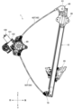
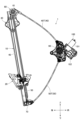
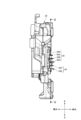
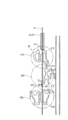
図1、図2に示すように、ウインドレギュレータ1は、ガイドレール10とスライダ20とを有している。ガイドレール10は、ウインドガラスW(図3参照)の駆動方向である上下方向に延びる。スライダ20は、ウインドガラスWを支持するとともに、ガイドレール10に上下方向(駆動方向)に摺動自在に支持される。ガイドレール10は、ブラケット30を介して、車両のドアパネル110a(図3参照)に固定される。
As shown in FIGS. 1 and 2, the
スライダ20には、当該スライダ20をガイドレール10に対して上下方向(駆動方向)に駆動する一対のワイヤ40、50のそれぞれの一端部が接続されている。
The
ガイドレール10の上端部には、ガイドプーリ60が、その回転軸孔に挿通した回転軸61によって回転自在に支持されている。ワイヤ40は、スライダ20からガイドレール10に沿って上方向に延び、ガイドプーリ60の外周面上に形成したワイヤガイド溝(図示略)によって支持される。ワイヤ40の進退に応じて、ガイドプーリ60は回転軸61を中心とした回転を行う。
A
ガイドレール10の下端部には、ガイド部材70が設けられている。ワイヤ50は、スライダ20からガイドレール10に沿って下方向に延びて、ガイド部材70に案内される。ガイド部材70は、ガイドレール10に対して固定されており、ガイド部材70に形成したワイヤガイド溝(図示略)によって進退可能にワイヤ50が支持される。
A
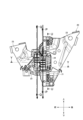
ガイドプーリ60から出たワイヤ40は、管状のアウタチューブ40Tに挿通され、アウタチューブ40Tが接続されるドラムハウジング80に設けた駆動ドラム90に巻回される。ガイド部材70から出たワイヤ50は、管状のアウタチューブ50Tに挿通され、アウタチューブ50Tが接続されるドラムハウジング80に設けた駆動ドラム90に巻回される。
The
ドラムハウジング80に対してモータユニット100が取り付けられる。このモータユニット100は、モータ101と、モータ101の出力軸の回転を減速させながら伝達する減速ギヤ列を内蔵したギヤボックス102とを有している。
A
アウタチューブ40Tは、一端がガイドプーリ60に接続され、他端がドラムハウジング80に接続され、このように両端位置が定められたアウタチューブ40T内でワイヤ40が進退可能となっている。アウタチューブ50Tは、一端がガイド部材70に接続され、他端がドラムハウジング80に接続され、このように両端位置が定められたアウタチューブ50T内でワイヤ50が進退可能となっている。
The
ドラムハウジング80は車両のドアパネル(図示略)に固定される。モータ101の駆動力によって駆動ドラム90が正逆に回転すると、ワイヤ40とワイヤ50の一方が駆動ドラム90に対する巻回量を大きくし、ワイヤ40とワイヤ50の他方が駆動ドラム90から繰り出されて、ワイヤ40とワイヤ50の牽引と弛緩の関係によってスライダ20がガイドレール10に沿って移動する。スライダ20の移動に応じてウインドガラスWが昇降する。
The
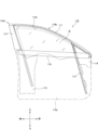
図3は、ウインドレギュレータ1を搭載した車両ドア110の側面図である。車両ドア110は、車両ボディ(図示略)の右側前席の側方に取り付けられる側面ドアであり、車両ボディには車両ドア110によって開閉されるドア開口(図示略)が形成されている。車両ドア110は、ドアパネル110a(一点鎖線で仮想的に示す)とドアフレーム110bとを備えている。ドアパネル110aの上縁部とドアフレーム110bとによって囲まれる窓開口110cが形成されている。
FIG. 3 is a side view of the
ドアフレーム110bは、車両ドア110の上縁に位置するアッパサッシュ111と、アッパサッシュ111からドアパネル110aへ向けて概ね上下方向に延びる立柱サッシュ112及びフロントサッシュ113とを有している。立柱サッシュ112はドアフレーム110bの最後部に位置しており、車両ドア110の後部上方の角隅部は、アッパサッシュ111の後端と立柱サッシュ112の上端が交わるドアコーナー部110dとなっている。ドアコーナー部110dでは、アッパサッシュ111の後端と立柱サッシュ112の上端が、接続部材を介して接続されている。立柱サッシュ112とフロントサッシュ113は略平行に延びており、立柱サッシュ112が窓開口110cの後縁を形成し、フロントサッシュ113が窓開口110cの前縁を形成する。また、アッパサッシュ111が窓開口110cの上縁を形成する。
The
立柱サッシュ112は、ドアコーナー部110dから下方(斜め下方)に延びてドアパネル内空間に挿入される。アッパサッシュ111は、ドアコーナー部110dから前方に延び、途中から前方に進むにつれて下方に湾曲して、ドアパネル内空間に達する。フロントサッシュ113は、アッパサッシュ111の途中位置から下方(斜め下方)に延びてドアパネル内空間に挿入される。アッパサッシュ111と立柱サッシュ112とフロントサッシュ113はそれぞれ、ドアパネル内空間内でドアパネル110aに対して固定される。
The
ドアパネル内空間には、前部にミラーブラケット114が配され、後部にロックブラケット115が配されている。ミラーブラケット114とロックブラケット115はそれぞれドアパネル110aに対して固定され、ミラーブラケット114にフロントサッシュ113が固定され、ロックブラケット115に立柱サッシュ112が固定される。ミラーブラケット114の一部は、ドアパネル110aよりも上方に突出してアッパサッシュ111とフロントサッシュ113の間の三角状のスペースに収まる形状をなし、ミラーブラケット114の当該部分に対してドアミラー(図示略)などが取り付けられる。ロックブラケット115にはドアロック機構(図示略)などが取り付けられる。
In the door panel interior space, a
ドアパネル内空間の上縁付近に、前後方向に延びるベルトラインリンフォース116が配されている。図示は省略するが、ベルトラインリンフォース116は、車内側に位置するインナリンフォースと車外側に位置するアウタリンフォースで構成されている。インナリンフォースは、その前端がミラーブラケット114に固定され、その後端がロックブラケット115に固定されている。
A
立柱サッシュ112とフロントサッシュ113に沿って昇降して窓開口110cを開閉させるウインドガラスWが設けられる。ウインドガラスWは、ウインドレギュレータ1によって、全閉位置(図1の位置)と全開位置との間で昇降し、全閉位置ではウインドガラスWの上縁がアッパサッシュ111まで達する。全閉位置から全開位置へ下降したウインドガラスWは、ドアパネル内空間に収容される。
A window glass W is provided along the
図4~図16を参照して、スライダ20の詳細構造ならびにガイドレール10への支持構造について説明する。
The detailed structure of the
図4は、ガイドレール10の断面形状を示す図である。ガイドレール10は、長手方向の断面で見たとき、前後方向に延びる主壁部11と、主壁部11の後端部から車外側に延びる側壁部12と、側壁部12の車外側の端部から後方に延びる離間壁部13と、主壁部11の前端部から車外側に延びた後に車内側に折り返される曲折壁部14と、曲折壁部14から前方に延びる離間壁部15とを有している。なお、ガイドレール10の断面形状は、図4に示したものに限定されず、種々の設計変更が可能である。例えば、側壁部12と離間壁部13と曲折壁部14と離間壁部15の少なくとも1つ(少なくとも一部)を省略してもよい。
FIG. 4 is a diagram showing a cross-sectional shape of the
ガイドレール10は、主壁部11の車外側の面に位置させて、図4の紙面直交方向である上下方向(駆動方向)に延びる2本(二筋)のグリス塗布領域Gaを有している。2本のグリス塗布領域Gaは、ワイヤ40とワイヤ50に対応している。とりわけ、2本のグリス塗布領域Gaのうち、ワイヤ40とワイヤ50に対向する部分が、ワイヤ40とワイヤ50の配策領域Gbとなっている。グリス塗布領域Ga(特にワイヤ40とワイヤ50の配策領域Gb)には、グリスGが塗布されており、ガイドレール10とスライダ20の摺動時に、ガイドレール10の主壁部11にワイヤ40とワイヤ50が当接(干渉)して異音や損傷が発生することが防止される。図4では、ガイドレール10のワイヤ40とワイヤ50の配策領域GbにグリスGが塗布されており、ガイドレール10のグリス塗布領域Gaのうち、ワイヤ40とワイヤ50の配策領域Gb以外にグリスGが塗布されていない状態を描いている。しかし、グリス塗布領域Gaの全体にグリスGが塗布されていてもよい。なお、ガイドレール10のグリス塗布領域Gaとワイヤ40とワイヤ50の配策領域Gbは、上下方向(駆動方向)に一直線である必要はなく、種々の設計変更が可能である。
The
図5はスライダ20を車内側から見た図であり、図6はスライダ20の側面図である。図5に示すように、スライダ20は、ワイヤ40の端部に設けられたワイヤエンド(図示略)を収納するワイヤエンド収納部21と、ワイヤ50の端部に設けられたワイヤエンド(図示略)を収納するワイヤエンド収納部22とを有している。ワイヤ40のワイヤエンドにはスプリング等の付勢手段が設けられており、この付勢手段の圧縮状態でワイヤ40のワイヤエンドがワイヤエンド収納部21に収納されることで、ワイヤ40にテンションが掛けられる。ワイヤ50のワイヤエンドにはスプリング等の付勢手段が設けられており、この付勢手段の圧縮状態でワイヤ50のワイヤエンドがワイヤエンド収納部22に収納されることで、ワイヤ50にテンションが掛けられる。また、スライダ20には、当該スライダ20にウインドガラスWを締結するための締結ボルトを挿入するボルト挿入孔23が形成されている。
FIG. 5 is a view of the
図7、図8は、図5のP-P線とQ-Q線に沿う第1、第2の断面図である。図7A、図8Aが図5のP-P線に沿う断面図であり、図7B、図8Bが図5のQ-Q線に沿う断面図である。 7 and 8 are first and second cross-sectional views taken along line PP and line QQ in FIG. 5. FIG. 7A and 8A are cross-sectional views taken along line PP in FIG. 5, and FIGS. 7B and 8B are cross-sectional views taken along line QQ in FIG. 5.
図7A、図8A等に示すように、スライダ20は、ガイドレール10とワイヤ40の対向面にグリスGを供給する多段爪部24を有している。多段爪部24は、ワイヤエンド収納部21内に収まるように(車幅方向に重なるように)形成されている。このため、スライダ20を成形するに当たって、接離方向に移動する一対の金型を接離方向と直交する方向に移動させずに済む(いわゆるスライドレス型を使用することができる)。
As shown in FIGS. 7A, 8A, etc., the
多段爪部24は、ガイドレール10のワイヤ40に対応するグリス塗布領域Gaに向かって突出する4つの爪部24A、24B、24C、24Dを有している。4つの爪部24A~24Dのうち隣接する爪部の間(爪部24Aと爪部24Bの間、爪部24Bと爪部24Cの間、爪部24Cと爪部24Dの間)には、グリスGを貯留するグリス貯留室が形成されている。
The
図8Aに示すように、多段爪部24は、4つの爪部24A~24Dの少なくとも1つ(図8Aの例では爪部24D)がガイドレール10のワイヤ40に対応するグリス塗布領域Gaに接触して弾性変形可能となっている(内寄せ状態)。具体的に、多段爪部24は、4つの爪部24A~24Dの根元に位置する根元撓み部24Eを有しており、この根元撓み部24Eが撓むことにより弾性変形可能となっている。図8Aの弾性変形状態(内寄せ状態)では、多段爪部24(4つの爪部24A~24D)、並びに、その上方に位置するグリス塗布突起24F及びグリス塗布壁24Gによって、ガイドレール10のワイヤ40に対応するグリス塗布領域Ga(配策領域Gb)からはみ出さないように段階的にグリスGが伸ばされて塗布される。
As shown in FIG. 8A, in the
図7Aに示すように、多段爪部24の自由状態(外寄せ状態)において、4つの爪部24A~24Dとガイドレール10のワイヤ40に対応するグリス塗布領域Gaの間の距離が異なっている。具体的に、多段爪部24の自由状態において、爪部24Aとグリス塗布領域Gaの間の距離が最も大きく、爪部24Bとグリス塗布領域Gaの間の距離が2番目に大きく、爪部24Cとグリス塗布領域Gaの間の距離が3番目に大きく、爪部24Dとグリス塗布領域Gaの間の距離が最も小さくなっている(図7Aの例では僅かに接触している)。図7Aの自由状態(外寄せ状態)では、ガイドレール10のワイヤ40に対応するグリス塗布領域Ga(配策領域Gb)に常に接触する爪部24Dにより、ガイドレール10のワイヤ40に対応するグリス塗布領域Ga(配策領域Gb)からはみ出さないようにグリスGが伸ばされて塗布される。
As shown in FIG. 7A, in the free state (extended state) of the
図10は、多段爪部24の詳細構造を示す拡大斜視図である。図10に示すように、多段爪部24の4つの爪部24A~24Dは、ガイドレール10のワイヤ40に対応するグリス塗布領域Gaに対向する切欠部24AX~24DXを有している。特に、切欠部24AX~24DXは、ガイドレール10のワイヤ40の配策領域Gbに対応している。例えば、多段爪部24の4つの爪部24A~24Dによってガイドレール10のワイヤ40に対応するグリス塗布領域GaにグリスGを塗布する場合、ガイドレール10のワイヤ40の配策領域Gbに塗布されたグリスGは、切欠部24AX~24DXによって配策領域Gbに留まっており、配策領域Gbからはみ出すことは殆どない。仮に、ガイドレール10のワイヤ40の配策領域Gbに塗布されたグリスGが配策領域Gbからはみ出しても、グリス塗布領域Gaから配策領域Gbに新たにグリスGが供給される(配策領域GbからグリスGがなくなることはない)。
FIG. 10 is an enlarged perspective view showing the detailed structure of the
図7B、図8B等に示すように、スライダ20は、ガイドレール10とワイヤ50の対向面にグリスGを供給する多段爪部25を有している。多段爪部25は、ワイヤエンド収納部22内に収まるように(車幅方向に重なるように)形成されている。このため、スライダ20を成形するに当たって、成形方向及び成形方向と直交する方向に関する一対の金型の一方を省略することができる(いわゆるスライドレス型を使用することができる)。
As shown in FIGS. 7B, 8B, and the like, the
多段爪部25は、ガイドレール10のワイヤ50に対応するグリス塗布領域Gaに向かって突出する3つの爪部25A、25B、25Cを有している。3つの爪部25A~25Cのうち隣接する爪部の間(爪部25Aと爪部25Bの間、爪部25Bと爪部25Cの間)には、グリスGを貯留するグリス貯留室が形成されている。
The
図8Bに示すように、多段爪部25は、3つの爪部25A~25Cの少なくとも1つ(図8Bの例では爪部25A~25C)がガイドレール10のワイヤ50に対応するグリス塗布領域Gaに接触して弾性変形可能となっている(内寄せ状態)。具体的に、多段爪部25は、3つの爪部25A~25Cの根元に位置する根元撓み部25Dを有しており、この根元撓み部25Dが撓むことにより弾性変形可能となっている。図8Bの弾性変形状態(内寄せ状態)では、多段爪部25(3つの爪部25A~25C)、並びに、その上方に位置するグリス塗布突起25Eによって、ガイドレール10のワイヤ50に対応するグリス塗布領域Ga(配策領域Gb)からはみ出さないように段階的にグリスGが伸ばされて塗布される。
As shown in FIG. 8B, the
図7Bに示すように、多段爪部25の自由状態(外寄せ状態)において、3つの爪部25A~25Cとガイドレール10のワイヤ50に対応するグリス塗布領域Gaの間の距離が異なっている。具体的に、多段爪部25の自由状態において、爪部25Aとグリス塗布領域Gaの間の距離が最も大きく、爪部25Bとグリス塗布領域Gaの間の距離が2番目に大きく、爪部25Cとグリス塗布領域Gaの間の距離が最も小さくなっている(図7Bの例では僅かに接触している)。図7Bの自由状態(外寄せ状態)では、ガイドレール10のワイヤ50に対応するグリス塗布領域Ga(配策領域Gb)に常に接触する爪部25Cにより、ガイドレール10のワイヤ50に対応するグリス塗布領域Ga(配策領域Gb)からはみ出さないようにグリスGが伸ばされて塗布される。
As shown in FIG. 7B, in the free state (extended state) of the
多段爪部24の4つの爪部24A~24Dの切欠部24AX~24DXと同様に、多段爪部25の3つの爪部25A~25Cは、ガイドレール10のワイヤ50に対応するグリス塗布領域Gaに対向する切欠部25AX~25CX(図9参照)を有している。特に、切欠部25AX~25CXは、ガイドレール10のワイヤ50の配策領域Gbに対応している。例えば、多段爪部25の3つの爪部25A~25Cによってガイドレール10のワイヤ50に対応するグリス塗布領域GaにグリスGを塗布する場合、ガイドレール10のワイヤ50の配策領域Gbに塗布されたグリスGは、切欠部25AX~25CXによって配策領域Gbに留まっており、配策領域Gbからはみ出すことは殆どない。仮に、ガイドレール10のワイヤ50の配策領域Gbに塗布されたグリスGが配策領域Gbからはみ出しても、グリス塗布領域Gaから配策領域Gbに新たにグリスGが供給される(配策領域GbからグリスGがなくなることはない)。
Similar to the cutout parts 24AX to 24DX of the four
図9は、図5のY-Y線に沿う断面図である。図9に示すように、ガイドレール10の主壁部11には貫通孔11Aが形成されているが、多段爪部24、25の形状、サイズ、配置等の各種パラメータは、多段爪部24、25が貫通孔11Aに引っ掛からないように且つ貫通孔11Aに落ちることがないように設定されている。また、ガイドレール10の主壁部11の貫通孔11Aの近傍(多段爪部24、25との接触部分)をプレスだれ面とすることで、貫通孔11Aの縁部への多段爪部24、25の干渉(引っ掛かり)が防止される。
FIG. 9 is a cross-sectional view taken along the YY line in FIG. As shown in FIG. 9, a through
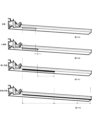
図11A~図11Dは、スライダ20の多段爪部24、25を用いて段階的にグリスGを伸ばして塗布する様子を示す図である。図11Aに示すように、爪部24Aとグリス塗布領域Gaの間の距離が最も大きく、図11Bに示すように、爪部24Bとグリス塗布領域Gaの間の距離が2番目に大きく、図11Cに示すように、爪部24Cとグリス塗布領域Gaの間の距離が3番目に大きく、図11Dに示すように、爪部24Dとグリス塗布領域Gaの間の距離が最も小さくなっている。また、図11Aに示すように、爪部25Bとグリス塗布領域Gaの間の距離が相対的に大きく、図11Bに示すように、爪部25Cとグリス塗布領域Gaの間の距離が相対的に小さくなっている。
FIGS. 11A to 11D are diagrams showing how the
従って、スライダ20をガイドレール10に対して一方向に摺動させて、スライダ20の多段爪部24を利用してグリスGを塗布するとき、爪部24AがグリスGの上澄み部分をかきとって引き延ばし、爪部24BがグリスGの上澄み部分をかきとって引き延ばし、爪部24CがグリスGの上澄み部分をかきとって引き延ばし、爪部24DがグリスGの上澄み部分をかきとって引き延ばす動作を順々に実行する。逆に、スライダ20をガイドレール10に対して他方向に摺動させるとき、少なくとも切欠部24AX~24DXの内部を通るグリスGは、ガイドレール10のワイヤ40の配策領域Gbに塗布されたままで留まる。
Therefore, when the
スライダ20をガイドレール10に対して一方向に摺動させて、スライダ20の多段爪部25を利用してグリスGを塗布するとき、爪部25AがグリスGの上澄み部分をかきとって引き延ばし、爪部25BがグリスGの上澄み部分をかきとって引き延ばし、爪部25CがグリスGの上澄み部分をかきとって引き延ばす動作を順々に実行する。逆に、スライダ20をガイドレール10に対して他方向に摺動させるとき、少なくとも切欠部25AX~25CXの内部を通るグリスGは、ガイドレール10のワイヤ50の配策領域Gbに塗布されたままで留まる。
When the
図12は、スライダ20の上部壁(グリス逃がし部)26と、戻し突起(グリス戻し部)27と、多段爪部24と、下部壁(グリス塗布壁)28とを示す図である。上方から下方に向かって、上部壁26と戻し突起27と多段爪部24と下部壁28が順に配置されている。
FIG. 12 is a diagram showing the upper wall (grease release part) 26, return protrusion (grease return part) 27,
上部壁26は、スライダ20をガイドレール10に対して摺動させるとき、ガイドレール10のワイヤ40に対応するグリス塗布領域GaからグリスGを前方に逃がす機能を有する。上部壁26は、ガイドレール10のワイヤ40に対応するグリス塗布領域Gaから離れるように傾斜するテーパ部26Tを有している。
The
戻し突起27は、スライダ20をガイドレール10に対して摺動させるとき、上部壁26が前方に逃がしたグリスGをガイドレール10のワイヤ40に対応するグリス塗布領域Gaに向かって後方に戻す機能を有する。戻し突起27は、ガイドレール10のワイヤ40に対応するグリス塗布領域Gaに近づくように傾斜するテーパ部27Tを有している。
The
多段爪部24は、ガイドレール10のワイヤ40に対応するグリス塗布領域Gaに向かって突出する4つの爪部24A~24Dを有しており、当該4つの爪部24A~24Dにより、ガイドレール10のワイヤ40に対応するグリス塗布領域Gaに段階的にグリスGを塗布する。
The
下部壁28は、ガイドレール10のワイヤ40に対応するグリス塗布領域Gaに向かって突出しており、ガイドレール10のワイヤ40に対応するグリス塗布領域GaにグリスGを塗布する。
The
スライダ20は、ガイドレール10に支持されるガイドレール支持部29A、29Bを有している。ガイドレール支持部29A、29Bは、例えば、ガイドレール10の主壁部11と側壁部12と離間壁部13と曲折壁部14と離間壁部15の少なくとも一部を咥え込んで支持する。そして、上部壁26はガイドレール支持部29Aに形成されており、下部壁28はガイドレール支持部29Bに形成されている。これにより、スライダ20にガイドレール10の支持構造とグリスGの塗布構造を併せ持たせて、スライダ20のコンパクト化を図るとともに、高いレイアウト性を実現することができる。
The
なお、ガイドレール10のワイヤ50に対応するグリス塗布領域Gaに対して、多段爪部25と協働するように、上部壁26と戻し突起27と下部壁28に相当する構成要素をスライダ20に形成してもよい。
Note that for the grease application area Ga corresponding to the
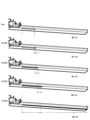
図13A~図13Dは、ガイドレール10のワイヤ40に対応するグリス塗布領域Gaに対してグリスGを塗布する工程を示す図である。図13A~図13Dは、上部壁26の上方にグリスGの塊を塗布した後、スライダ20をガイドレール10に対して上方に摺動させることにより、ガイドレール10のワイヤ40に対応するグリス塗布領域Gaに対してグリスGを塗布する例を示している。
13A to 13D are diagrams showing the process of applying grease G to the grease application area Ga corresponding to the
図13Aは、スライダ20をガイドレール10に対して上方に摺動させる前の初期状態であり、上部壁26の上方にグリスGの塊が塗布されている。
FIG. 13A shows an initial state before the
図13Bでは、スライダ20をガイドレール10に対して上方に摺動させるに連れて、上部壁26のテーパ部26TがグリスGにぶつかって、ガイドレール10のワイヤ40に対応するグリス塗布領域GaからグリスGが前方に逃がされる。
In FIG. 13B, as the
図13Cでは、スライダ20をガイドレール10に対して上方に摺動させるに連れて、戻し突起27のテーパ部27TがグリスGにぶつかって、ガイドレール10のワイヤ40に対応するグリス塗布領域Gaに向かってグリスGが後方に戻される。
In FIG. 13C, as the
図13Dでは、スライダ20をガイドレール10に対して上方に摺動させるに連れて、多段爪部24の4つの爪部24A~24Dと下部壁28により、ガイドレール10のワイヤ40に対応するグリス塗布領域Gaに段階的にグリスGが塗布される。
In FIG. 13D, as the
ここまで説明した多段爪部24、グリス塗布突起24F、グリス塗布壁24G、多段爪部25、グリス塗布突起25E、上部壁26、戻し突起27及び下部壁28は、ウインドガラスWの駆動方向である上下方向に沿って設けられるとともに、グリス塗布領域Gaに段階的にグリスGを塗布する「複数のグリス塗布部」を構成している。例えば、多段爪部24を単体で見れば、4つの爪部24A~24Dが「複数のグリス塗布部」に相当し、多段爪部25を単体で見れば、3つの爪部25A~25Cが「複数のグリス塗布部」に相当する。また、多段爪部24、グリス塗布突起24F、グリス塗布壁24G、上部壁26、戻し突起27及び下部壁28の少なくとも2つの組み合わせを「複数のグリス塗布部」とすることもできる。少なくとも2つの組み合わせとしては、例えば、多段爪部24と上部壁26と戻し突起27の組み合わせ、多段爪部24と下部壁28の組み合わせ、多段爪部24と上部壁26と戻し突起27と下部壁28の組み合わせ、上部壁26と戻し突起27の組み合わせ、上部壁26と戻し突起27と下部壁28の組み合わせが挙げられる。「複数のグリス塗布部」による段階的なグリス塗布によって、スライダ20からガイドレール10への好適なグリス塗布が実現可能となる。
The
また、ガイドレール10の車両前後幅を小さくしようとすると、スライダ20のガイドレール保持部とワイヤ摺動部が車両上下方向で重なってしまい、ワイヤ摺動部のために塗布したグリスがガイドレール保持部によって位置ずれするおそれがある。この点、本実施形態では、上部壁(グリス逃がし部)26と戻し突起(グリス戻し部)27を形成しているので、たとえスライダ20のガイドレール保持部とワイヤ摺動部が車両上下方向で重なっている場合でも、ガイドレール保持部を避けつつ、ワイヤ摺動部にグリスを供給することが可能となる。
Furthermore, if the width of the
図14A~図14Dは、内寄せ状態におけるグリスGの引き延ばしのイメージを示す工程図である。図14AはグリスGの引き延ばし前の初期状態であり、図14Bは上部壁26によるグリスGの引き延ばし状態であり、図14Cは戻し突起27によるグリスGの引き延ばし状態であり、図14Dは多段爪部24(4つの爪部24A~24D)によるグリスGの引き延ばし状態である。内寄せ状態では、多段爪部24の4つの爪部24A~24Dがガイドレール10のグリス塗布領域Ga(ワイヤの配策領域Gb)に接触しているので、多段爪部24(4つの爪部24A~24D)によるグリスGの引き延ばし量が相対的に大きくなっている。
FIGS. 14A to 14D are process diagrams showing an image of stretching the grease G in the inward state. 14A shows the initial state before the grease G is stretched, FIG. 14B shows the grease G stretched by the
図15A~図15Eは、外寄せ状態におけるグリスGの引き延ばしのイメージを示す工程図である。図15AはグリスGの引き延ばし前の初期状態であり、図15Bは爪部24A(1段目壁)によるグリスGの引き延ばし状態であり、図15Cは爪部24B(2段目壁)によるグリスGの引き延ばし状態であり、図15Dは爪部24C(3段目壁)によるグリスGの引き延ばし状態であり、図15Eは爪部24D(4段目壁)によるグリスGの引き延ばし状態である。外寄せ状態では、多段爪部24の爪部24D(4段目壁)がガイドレール10のグリス塗布領域Ga(ワイヤの配策領域Gb)に常時接触しているので、多段爪部24の爪部24D(4段目壁)によるグリスGの引き延ばし量が相対的に大きくなっている。
FIGS. 15A to 15E are process diagrams illustrating the stretching of the grease G in the external state. 15A shows the initial state before the grease G is stretched, FIG. 15B shows the grease G being stretched by the
図16は、ガイドレール10とブラケット120の結合構造を示す断面図である。本実施形態では、スライダ20に多段爪部24、25を設けていることから、ガイドレール10とブラケット120の結合にバーリングカシメを用いた場合、カシメ部に多段爪部24、25が引っ掛かるおそれがある。そこで、本実施形態では、ガイドレール10とブラケット120の結合にTOXカシメを用いている。TOXカシメは、ブラケット120にだれ面121を形成し、当該だれ面121の内部にガイドレール10を入り込ませた窪み部16を形成するものである。ガイドレール10の窪み部16とブラケット120のだれ面121は、スライダ20に多段爪部24、25が引っ掛かったり落ちたりしないような形状、サイズ、配置となっている。なお、上記の結合構造は、ガイドレール10と車両ドア110のドアパネル110aの結合構造に適用してもよい。
FIG. 16 is a sectional view showing a coupling structure between the
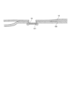
上述の実施形態(例えば図1~図15に示した実施形態)では、ガイドレール10の主壁部11にグリス塗布領域Gaを設定して、スライダ20に、グリス塗布領域Gaに段階的にグリスを塗布する「複数のグリス塗布部」を設ける場合を例示して説明した。これに対して、ガイドレール10の側壁部12にグリス塗布領域Gcを設定して、スライダ20に、グリス塗布領域Gcに段階的にグリスを塗布する「複数のグリス塗布部」を設ける態様も可能である。この変形実施例について、図17、図18を参照して、具体的に説明する。図17は、図5のU-U線に沿う断面図であり、図18は、図6のV-V線に沿う断面図であり、内寄せ状態におけるグリスGの引き延ばしを描いている。
In the embodiments described above (for example, the embodiments shown in FIGS. 1 to 15), a grease application area Ga is set on the
図17、図18において、ガイドレール10の側壁部12の上部に設定したグリス塗布領域Gcの一部に予めグリスGを塗布(貯留)しておき、スライダ20をガイドレール10に沿って上昇させる場合を想定する。この場合、アッパ側シュー部に形成した第1のグリス塗布部210(図18)と、樹脂ばね構造として形成した第2のグリス塗布部220(図17)と、ロア側シュー部に形成した第3のグリス塗布部230(図18)とから構成される多段構造により、ガイドレール10の側壁部12に設定したグリス塗布領域GcにグリスGが塗布されていく。すなわち、ガイドレール10は、上下方向(駆動方向)に延びるグリス塗布領域Gcを有しており、スライダ20は、上下方向(駆動方向)に沿って設けられるとともに、グリス塗布領域Gcに段階的にグリスGを塗布する複数のグリス塗布部として、第1のグリス塗布部210と第2のグリス塗布部220と第3のグリス塗布部230を有している。
17 and 18, grease G is applied (reserved) in advance to a part of the grease application area Gc set at the upper part of the
第1のグリス塗布部210は、アッパ側シュー部のシュー先端形状部として、上方に向かって拡径するテーパ囲い込み形状部211を有している。テーパ囲い込み形状部211は、グリスGを必要部位(グリス塗布領域Gc)に供給する機能、及び、シューの摺動部外にグリスGが溢れ出ないようにする機能を有している。また、第1のグリス塗布部210は、シューの摺動部にグリスGを誘い込むための面取部212を有している。
The first
第2のグリス塗布部220は、ガイドレール10の側壁部12に向かって突出するグリス塗布爪部(弾性爪部)221を有している。グリス塗布爪部221は、ガイドレール10の側壁部12に弾接して撓みながら、ガイドレール10の側壁部12の上部に設定したグリス塗布領域GcにグリスGを塗布していく(引き延ばしていく)。
The second
第3のグリス塗布部230は、ロア側シュー部のシュー先端形状部として、上方に向かって拡径するテーパ囲い込み形状部231を有している。テーパ囲い込み形状部231は、ロア側シュー部にグリスGを誘い込んで供給する機能を有している。また、第3のグリス塗布部230は、シューの摺動部にグリスGを誘い込むための面取部232を有している。
The third
本発明の実施の形態は上記実施形態やその変形例に限定されるものではなく、本発明の技術的思想の趣旨を逸脱しない範囲において様々に変更、置換、変形されてもよい。さらには、技術の進歩又は派生する別技術によって、本発明の技術的思想を別の仕方で実現することができれば、その方法を用いて実施されてもよい。したがって、特許請求の範囲は、本発明の技術的思想の範囲内に含まれ得る全ての実施形態をカバーしている。 The embodiments of the present invention are not limited to the above-described embodiments or modifications thereof, and may be variously changed, replaced, and modified without departing from the spirit of the technical idea of the present invention. Furthermore, if the technical idea of the present invention can be realized in a different manner due to advances in technology or other derived technologies, it may be implemented using that method. Accordingly, the claims cover all embodiments that may fall within the scope of the invention.
以上の実施形態では、多段爪部24が4つの爪部24A~24Dを有しており、多段爪部25が3つの爪部25A~25Cが有している場合を例示して説明したが、多段爪部の爪部の数には自由度があり、種々の設計変更が可能である(多段爪部の爪部は複数あればよい)。
In the above embodiment, the
以上の実施形態では、複数のグリス塗布部の一構成要素である上部壁26と下部壁28をガイドレール支持部29Aとガイドレール支持部29Bに形成した場合を例示して説明したが、複数のグリス塗布部の他の構成要素をガイドレール支持部に形成してもよい。すなわち、複数のグリス塗布部の少なくとも1つがガイドレール支持部に設けられていればよい。
In the above embodiment, the
1 ウインドレギュレータ
10 ガイドレール
11 主壁部
11A 貫通孔
12 側壁部
13 離間壁部
14 曲折壁部
15 離間壁部
16 窪み部
20 スライダ
21 22 ワイヤエンド収納部
23 ボルト挿入孔
24 多段爪部(複数のグリス塗布部)
24A 24B 24C 24D 爪部
24AX 24BX 24CX 24DX 切欠部
24E 根元撓み部
24F グリス塗布突起(複数のグリス塗布部)
24G グリス塗布壁(複数のグリス塗布部)
25 多段爪部(複数のグリス塗布部)
25A 25B 25C 爪部
25AX 25BX 25CX 切欠部
25D 根元撓み部
25E グリス塗布突起(複数のグリス塗布部)
26 上部壁(グリス逃がし部、複数のグリス塗布部)
26T テーパ部
27 戻し突起(グリス戻し部、複数のグリス塗布部)
27T テーパ部
28 下部壁(グリス塗布壁、複数のグリス塗布部)
29 ガイドレール支持部
30 ブラケット
40 50 ワイヤ
40T 50T アウタチューブ
60 ガイドプーリ
61 回転軸
70 ガイド部材
80 ドラムハウジング
90 駆動ドラム
100 モータユニット
101 モータ
102 ギヤボックス
110 車両ドア
110a ドアパネル
110b ドアフレーム
110c 窓開口
110d ドアコーナー部
111 アッパサッシュ
112 立柱サッシュ
113 フロントサッシュ
114 ミラーブラケット
115 ロックブラケット
116 ベルトラインリンフォース
120 ブラケット
121 だれ面
210 第1のグリス塗布部(複数のグリス塗布部)
211 テーパ囲い込み形状部
212 面取部
220 第2のグリス塗布部(複数のグリス塗布部)
221 グリス塗布爪部(弾性爪部)
230 第3のグリス塗布部(複数のグリス塗布部)
231 テーパ囲い込み形状部
232 面取部
G グリス
Ga グリス塗布領域
Gb ワイヤの配策領域
Gc グリス塗布領域
W ウインドガラス
1
24G Grease coated wall (multiple grease coated parts)
25 Multi-stage claw part (multiple grease application parts)
26 Upper wall (grease relief section, multiple grease application sections)
26T
27T
29 Guide
211 Tapered
221 Grease application claw part (elastic claw part)
230 Third grease application part (multiple grease application parts)
231 Tapered
Claims (9)
前記ウインドガラスを支持するとともに、前記ガイドレールに前記駆動方向に摺動自在に支持されるスライダと、
を有するウインドレギュレータであって、
前記ガイドレールは、前記駆動方向に延びるグリス塗布領域を有し、
前記スライダは、前記駆動方向に沿って設けられるとともに、前記グリス塗布領域に段階的にグリスを塗布する複数のグリス塗布部を有する、
ことを特徴とするウインドレギュレータ。 a guide rail extending in the driving direction of the windshield;
a slider that supports the window glass and is slidably supported by the guide rail in the driving direction;
A window regulator having
The guide rail has a grease application area extending in the driving direction,
The slider is provided along the drive direction and has a plurality of grease application parts that apply grease to the grease application area in stages.
A window regulator characterized by:
ことを特徴とする請求項1に記載のウインドレギュレータ。 The plurality of grease application parts include a multistage claw part having a plurality of claw parts protruding toward the grease application area.
The window regulator according to claim 1, characterized in that:
前記多段爪部の自由状態において、前記複数の爪部と前記グリス塗布領域の間の距離が異なる、
ことを特徴とする請求項2に記載のウインドレギュレータ。 The multi-step claw portion is elastically deformable when at least one of the plurality of claw portions comes into contact with the grease application area;
In the free state of the multistage claw portion, the distances between the plurality of claw portions and the grease application area are different;
The window regulator according to claim 2, characterized in that:
ことを特徴とする請求項2又は請求項3に記載のウインドレギュレータ。 Each of the plurality of claws has a notch facing the grease application area.
The window regulator according to claim 2 or claim 3, characterized in that:
前記切欠部は、前記ワイヤの配策領域に対向する、
ことを特徴とする請求項4に記載のウインドレギュレータ。 The grease application area has a wiring area for a wire that drives the slider in the drive direction,
the cutout portion faces the wiring area;
The window regulator according to claim 4, characterized in that:
ことを特徴とする請求項1から請求項5のいずれかに記載のウインドレギュレータ。 The plurality of grease application parts include a grease release part that releases the grease from the grease application area, and a grease return part that returns the grease released by the grease release part to the grease application area.
The window regulator according to any one of claims 1 to 5, characterized in that:
前記グリス戻し部は、前記グリス塗布領域に近づくように傾斜するテーパ部を有する、
ことを特徴とする請求項6に記載のウインドレギュレータ。 The grease relief part has a tapered part that slopes away from the grease application area,
The grease return portion has a tapered portion that slopes toward the grease application area.
The window regulator according to claim 6, characterized in that:
ことを特徴とする請求項1から請求項7のいずれかに記載のウインドレギュレータ。 The plurality of grease application parts include a grease application wall protruding toward the grease application area.
The window regulator according to any one of claims 1 to 7, characterized in that:
前記複数のグリス塗布部の少なくとも1つは、前記ガイドレール支持部に設けられる、
ことを特徴とする請求項1から請求項8のいずれかに記載のウインドレギュレータ。 The slider has a guide rail support part supported by the guide rail,
At least one of the plurality of grease application parts is provided on the guide rail support part,
The window regulator according to any one of claims 1 to 8, characterized in that:
Priority Applications (4)
| Application Number | Priority Date | Filing Date | Title |
|---|---|---|---|
| JP2020030155A JP7351237B2 (en) | 2020-02-26 | 2020-02-26 | window regulator |
| CN202180008888.1A CN114945729B (en) | 2020-02-26 | 2021-02-19 | Window regulators |
| US17/904,519 US12037835B2 (en) | 2020-02-26 | 2021-02-19 | Window regulator |
| PCT/JP2021/006300 WO2021172186A1 (en) | 2020-02-26 | 2021-02-19 | Window regulator |
Applications Claiming Priority (1)
| Application Number | Priority Date | Filing Date | Title |
|---|---|---|---|
| JP2020030155A JP7351237B2 (en) | 2020-02-26 | 2020-02-26 | window regulator |
Publications (2)
| Publication Number | Publication Date |
|---|---|
| JP2021134518A JP2021134518A (en) | 2021-09-13 |
| JP7351237B2 true JP7351237B2 (en) | 2023-09-27 |
Family
ID=77490187
Family Applications (1)
| Application Number | Title | Priority Date | Filing Date |
|---|---|---|---|
| JP2020030155A Active JP7351237B2 (en) | 2020-02-26 | 2020-02-26 | window regulator |
Country Status (4)
| Country | Link |
|---|---|
| US (1) | US12037835B2 (en) |
| JP (1) | JP7351237B2 (en) |
| CN (1) | CN114945729B (en) |
| WO (1) | WO2021172186A1 (en) |
Families Citing this family (2)
| Publication number | Priority date | Publication date | Assignee | Title |
|---|---|---|---|---|
| JP2021156148A (en) * | 2020-03-30 | 2021-10-07 | シロキ工業株式会社 | Wire type regulator |
| JP7789635B2 (en) * | 2022-07-28 | 2025-12-22 | 株式会社ハイレックスコーポレーション | Carrier Plate and Window Regulator |
Citations (3)
| Publication number | Priority date | Publication date | Assignee | Title |
|---|---|---|---|---|
| US20020014039A1 (en) | 2000-07-04 | 2002-02-07 | Sophie Merlet | Window regulator having a slider with silent displacement |
| JP2017133228A (en) | 2016-01-27 | 2017-08-03 | シロキ工業株式会社 | Window regulator |
| JP2017203312A (en) | 2016-05-12 | 2017-11-16 | シロキ工業株式会社 | Window regulator |
Family Cites Families (11)
| Publication number | Priority date | Publication date | Assignee | Title |
|---|---|---|---|---|
| JPS58181885U (en) * | 1982-05-31 | 1983-12-05 | ダイキヨ−・ペパスト株式会社 | Guide device for vehicle window glass opening/closing device |
| JPH0718294B2 (en) * | 1989-04-14 | 1995-03-01 | 旭化成工業株式会社 | Resin carrier plate |
| JP3269259B2 (en) * | 1994-05-24 | 2002-03-25 | 日産自動車株式会社 | Carrier plate structure of wire drum type regulator |
| JP3331747B2 (en) * | 1994-06-21 | 2002-10-07 | アイシン精機株式会社 | Windregulator device |
| JP6662577B2 (en) * | 2015-04-23 | 2020-03-11 | シロキ工業株式会社 | How to attach the wind regulator to the vehicle |
| JP6846116B2 (en) * | 2016-04-12 | 2021-03-24 | シロキ工業株式会社 | Vehicle opening / closing body drive device |
| JP6723826B2 (en) * | 2016-05-24 | 2020-07-15 | シロキ工業株式会社 | Wire type window regulator |
| JP7187980B2 (en) * | 2018-10-29 | 2022-12-13 | 株式会社アイシン | Window regulator and its assembly method |
| JP7187981B2 (en) * | 2018-10-29 | 2022-12-13 | 株式会社アイシン | Window regulator and its assembly method |
| JP6954956B2 (en) * | 2019-06-27 | 2021-10-27 | 株式会社ハイレックスコーポレーション | Object moving device |
| JP7152991B2 (en) * | 2019-06-28 | 2022-10-13 | 株式会社ハイレックスコーポレーション | vehicle door structure |
-
2020
- 2020-02-26 JP JP2020030155A patent/JP7351237B2/en active Active
-
2021
- 2021-02-19 US US17/904,519 patent/US12037835B2/en active Active
- 2021-02-19 CN CN202180008888.1A patent/CN114945729B/en active Active
- 2021-02-19 WO PCT/JP2021/006300 patent/WO2021172186A1/en not_active Ceased
Patent Citations (3)
| Publication number | Priority date | Publication date | Assignee | Title |
|---|---|---|---|---|
| US20020014039A1 (en) | 2000-07-04 | 2002-02-07 | Sophie Merlet | Window regulator having a slider with silent displacement |
| JP2017133228A (en) | 2016-01-27 | 2017-08-03 | シロキ工業株式会社 | Window regulator |
| JP2017203312A (en) | 2016-05-12 | 2017-11-16 | シロキ工業株式会社 | Window regulator |
Also Published As
| Publication number | Publication date |
|---|---|
| WO2021172186A1 (en) | 2021-09-02 |
| US12037835B2 (en) | 2024-07-16 |
| US20230081555A1 (en) | 2023-03-16 |
| CN114945729A (en) | 2022-08-26 |
| JP2021134518A (en) | 2021-09-13 |
| CN114945729B (en) | 2024-06-14 |
Similar Documents
| Publication | Publication Date | Title |
|---|---|---|
| JP7351237B2 (en) | window regulator | |
| US7537265B2 (en) | Vehicle rear structure | |
| US8075050B2 (en) | Sunroof system | |
| US7086684B2 (en) | Extendable protective awning and motor vehicle having a protective awning | |
| JP4728938B2 (en) | Power supply device for sliding door | |
| US7053306B2 (en) | Electricity-feeding device | |
| JP6844815B2 (en) | Vehicle wire wind regulator device | |
| WO2013129206A1 (en) | Vehicle door opening/closing device | |
| JPS5827129B2 (en) | Sliding roof structure for vehicles | |
| JP4057821B2 (en) | Power supply device for sliding door | |
| CN112145018A (en) | Object moving device | |
| JP4256826B2 (en) | Power supply device | |
| JP2025170085A (en) | How to install the window regulator and guide rail | |
| JP2009255724A (en) | Automatic opening/closing device for vehicle | |
| CN100442616C (en) | Wire harness guide protector, excessively long wire collection structure and former fixing method | |
| JP2008245392A (en) | Electrical connection structure | |
| JP4826381B2 (en) | Vehicle tonneau cover device | |
| JP5146773B2 (en) | Sunshade device for automobile | |
| JP2010246317A (en) | Charging cord storage structure for electric vehicles | |
| JP2519721Y2 (en) | Guide mechanism for vehicle opening and closing roof device | |
| JP4895756B2 (en) | Sliding door self-closing device | |
| JP3990932B2 (en) | Power supply structure for sliding door | |
| JP4297375B2 (en) | Power supply device for sliding door | |
| WO2015053190A1 (en) | Power supply structure for sliding door | |
| JP5781841B2 (en) | Door harness wiring structure |
Legal Events
| Date | Code | Title | Description |
|---|---|---|---|
| A711 | Notification of change in applicant |
Free format text: JAPANESE INTERMEDIATE CODE: A711 Effective date: 20220314 |
|
| A621 | Written request for application examination |
Free format text: JAPANESE INTERMEDIATE CODE: A621 Effective date: 20221214 |
|
| TRDD | Decision of grant or rejection written | ||
| A01 | Written decision to grant a patent or to grant a registration (utility model) |
Free format text: JAPANESE INTERMEDIATE CODE: A01 Effective date: 20230815 |
|
| A61 | First payment of annual fees (during grant procedure) |
Free format text: JAPANESE INTERMEDIATE CODE: A61 Effective date: 20230828 |
|
| R150 | Certificate of patent or registration of utility model |
Ref document number: 7351237 Country of ref document: JP Free format text: JAPANESE INTERMEDIATE CODE: R150 |