WO2017195460A1 - テンプレートアセンブリの選別方法及びワークの研磨方法並びにテンプレートアセンブリ - Google Patents
テンプレートアセンブリの選別方法及びワークの研磨方法並びにテンプレートアセンブリ Download PDFInfo
- Publication number
- WO2017195460A1 WO2017195460A1 PCT/JP2017/010203 JP2017010203W WO2017195460A1 WO 2017195460 A1 WO2017195460 A1 WO 2017195460A1 JP 2017010203 W JP2017010203 W JP 2017010203W WO 2017195460 A1 WO2017195460 A1 WO 2017195460A1
- Authority
- WO
- WIPO (PCT)
- Prior art keywords
- template
- workpiece
- template assembly
- flatness
- polishing
- Prior art date
Links
Images

Classifications
-
- B—PERFORMING OPERATIONS; TRANSPORTING
- B24—GRINDING; POLISHING
- B24B—MACHINES, DEVICES, OR PROCESSES FOR GRINDING OR POLISHING; DRESSING OR CONDITIONING OF ABRADING SURFACES; FEEDING OF GRINDING, POLISHING, OR LAPPING AGENTS
- B24B37/00—Lapping machines or devices; Accessories
- B24B37/27—Work carriers
- B24B37/30—Work carriers for single side lapping of plane surfaces
- B24B37/32—Retaining rings
-
- B—PERFORMING OPERATIONS; TRANSPORTING
- B24—GRINDING; POLISHING
- B24B—MACHINES, DEVICES, OR PROCESSES FOR GRINDING OR POLISHING; DRESSING OR CONDITIONING OF ABRADING SURFACES; FEEDING OF GRINDING, POLISHING, OR LAPPING AGENTS
- B24B37/00—Lapping machines or devices; Accessories
- B24B37/27—Work carriers
- B24B37/30—Work carriers for single side lapping of plane surfaces
-
- G—PHYSICS
- G01—MEASURING; TESTING
- G01B—MEASURING LENGTH, THICKNESS OR SIMILAR LINEAR DIMENSIONS; MEASURING ANGLES; MEASURING AREAS; MEASURING IRREGULARITIES OF SURFACES OR CONTOURS
- G01B11/00—Measuring arrangements characterised by the use of optical techniques
- G01B11/02—Measuring arrangements characterised by the use of optical techniques for measuring length, width or thickness
-
- G—PHYSICS
- G01—MEASURING; TESTING
- G01B—MEASURING LENGTH, THICKNESS OR SIMILAR LINEAR DIMENSIONS; MEASURING ANGLES; MEASURING AREAS; MEASURING IRREGULARITIES OF SURFACES OR CONTOURS
- G01B11/00—Measuring arrangements characterised by the use of optical techniques
- G01B11/24—Measuring arrangements characterised by the use of optical techniques for measuring contours or curvatures
-
- G—PHYSICS
- G01—MEASURING; TESTING
- G01B—MEASURING LENGTH, THICKNESS OR SIMILAR LINEAR DIMENSIONS; MEASURING ANGLES; MEASURING AREAS; MEASURING IRREGULARITIES OF SURFACES OR CONTOURS
- G01B11/00—Measuring arrangements characterised by the use of optical techniques
- G01B11/30—Measuring arrangements characterised by the use of optical techniques for measuring roughness or irregularity of surfaces
- G01B11/306—Measuring arrangements characterised by the use of optical techniques for measuring roughness or irregularity of surfaces for measuring evenness
-
- H—ELECTRICITY
- H01—ELECTRIC ELEMENTS
- H01L—SEMICONDUCTOR DEVICES NOT COVERED BY CLASS H10
- H01L21/00—Processes or apparatus adapted for the manufacture or treatment of semiconductor or solid state devices or of parts thereof
- H01L21/02—Manufacture or treatment of semiconductor devices or of parts thereof
- H01L21/04—Manufacture or treatment of semiconductor devices or of parts thereof the devices having potential barriers, e.g. a PN junction, depletion layer or carrier concentration layer
- H01L21/18—Manufacture or treatment of semiconductor devices or of parts thereof the devices having potential barriers, e.g. a PN junction, depletion layer or carrier concentration layer the devices having semiconductor bodies comprising elements of Group IV of the Periodic Table or AIIIBV compounds with or without impurities, e.g. doping materials
- H01L21/30—Treatment of semiconductor bodies using processes or apparatus not provided for in groups H01L21/20 - H01L21/26
- H01L21/302—Treatment of semiconductor bodies using processes or apparatus not provided for in groups H01L21/20 - H01L21/26 to change their surface-physical characteristics or shape, e.g. etching, polishing, cutting
- H01L21/304—Mechanical treatment, e.g. grinding, polishing, cutting
-
- H—ELECTRICITY
- H01—ELECTRIC ELEMENTS
- H01L—SEMICONDUCTOR DEVICES NOT COVERED BY CLASS H10
- H01L21/00—Processes or apparatus adapted for the manufacture or treatment of semiconductor or solid state devices or of parts thereof
- H01L21/02—Manufacture or treatment of semiconductor devices or of parts thereof
- H01L21/04—Manufacture or treatment of semiconductor devices or of parts thereof the devices having potential barriers, e.g. a PN junction, depletion layer or carrier concentration layer
- H01L21/18—Manufacture or treatment of semiconductor devices or of parts thereof the devices having potential barriers, e.g. a PN junction, depletion layer or carrier concentration layer the devices having semiconductor bodies comprising elements of Group IV of the Periodic Table or AIIIBV compounds with or without impurities, e.g. doping materials
- H01L21/30—Treatment of semiconductor bodies using processes or apparatus not provided for in groups H01L21/20 - H01L21/26
- H01L21/302—Treatment of semiconductor bodies using processes or apparatus not provided for in groups H01L21/20 - H01L21/26 to change their surface-physical characteristics or shape, e.g. etching, polishing, cutting
- H01L21/306—Chemical or electrical treatment, e.g. electrolytic etching
- H01L21/30625—With simultaneous mechanical treatment, e.g. mechanico-chemical polishing
Definitions
- the present invention relates to a template assembly selection method, a workpiece polishing method, and a template assembly.
- a template (TP) in which a retainer ring such as glass epoxy (GE) is bonded to a backing pad (BP) is widely used.
- TP is usually used as a base ring made of a material such as Ti, PVC, ceramic, or a template assembly (TP ASSY) attached to a base plate.
- TP ASSY template assembly
- the inner diameter of the retainer ring is designed to be slightly larger than the workpiece diameter, and the outer diameter is designed to be smaller than the outer diameter of the base ring or base plate.
- 4 to 12 polishing heads are attached to a polishing machine, and a template assembly is mounted on each polishing head.
- Patent Document 1 there is a method of measuring pocket depth in the circumferential direction by interlocking an inline non-contact laser displacement meter and a polishing head, and there is a method of applying this.
- the laser scan width is usually several millimeters, and a distance of generally several tens of millimeters from the outer periphery of the base ring to the inner peripheral end of the retainer ring cannot be covered by one measurement.
- the template assembly to be measured has two steps (base and retainer ring, retainer ring and back pad). If the step portion is not directly under the laser beam, the corner of the step becomes a shadow. Therefore, it is known that accurate reflected light cannot be obtained, and in particular, the accuracy of measuring the pocket depth is deteriorated.
- Patent Document 1 describes a method for measuring a pocket depth of a template.
- Patent Document 2 discloses that the height of the retainer ring is measured by a laser displacement meter in a non-contact manner.
- Patent Document 3 discloses that the flatness of the template surface and the backing pad surface is measured with a laser displacement meter.
- Patent Document 4 discloses that the thickness and height of a retainer ring are measured with a laser displacement meter.
- the flatness of the retainer ring and the P.P. D. No prior art was found to measure the template assembly.
- the present invention has been made in view of the above-described problems, and an object of the present invention is to provide a template assembly selection method capable of adjusting variations in flatness of a workpiece after polishing.
- the workpiece when the surface of the workpiece is polished by being brought into sliding contact with the polishing cloth affixed on the surface plate, the workpiece is attached to the polishing head and held in order to hold the workpiece.
- a method of selecting a template assembly to be used A template having a back pad that holds the back surface of the workpiece and a retainer ring that is positioned on the back pad and holds an edge portion of the workpiece, a base ring having an outer diameter larger than the outer diameter of the template, or A preparation step of preparing a template assembly concentrically bonded to the base plate;
- On the template side of the template assembly On the template side of the template assembly, a measurement step of measuring the distribution of height positions of the retainer ring and the back pad in a non-destructive manner when the outer peripheral surface of the base ring or the base plate is used as a reference plane; From the distribution of the measured height position, the calculation step of calculating the flatness of the retainer ring and the average step amount of the retainer ring and the back
- the flatness of the retainer ring can be measured before mounting the polishing head, and the template is based on the flatness and the average step amount.
- the assembly can be sorted. Therefore, if the workpiece is polished using the template assembly selected in this way, the variation in flatness of the workpiece after polishing can be adjusted. In particular, it is possible to prevent variations in flatness. Furthermore, it can prevent that the retainer ring surface is damaged by performing the said measurement process nondestructively. For this reason, dust generation can be prevented, and scratching of the workpiece after polishing can also be prevented.
- the outer diameter is 10 mm or more larger than the outer diameter of the template and the surface roughness is Ra ⁇ 6.3 ⁇ m.
- the retainer By using a laser displacement meter to alternately measure the distribution of the height position for each circumference by laser scanning in the circumferential direction of the template assembly and slide the template assembly in the radial direction, the retainer It is preferable to measure the distribution of the height positions of the ring and the back pad in a lump.
- the distribution of the height position can be collectively measured, and the flatness of the retainer ring and the average step amount of the retainer ring and the back pad can be collectively measured in the circumferential direction with high accuracy, high throughput, and non-destructiveness. Can be sought.
- a plurality of the template assemblies are prepared, Performing the measurement step and the calculation step for each template assembly; It is preferable to select template assemblies having a flatness difference of 5 ⁇ m or less and a difference in average step amount of 5 ⁇ m or less among the plurality of template assemblies.
- a workpiece polishing method Provided is a workpiece polishing method, wherein the template assembly selected by the template assembly selection method of the present invention as described above is mounted on the polishing head, and the workpiece is held and polished.
- the workpiece is polished using the template assembly selected by the template assembly selection method of the present invention, it is possible to prevent variations in the flatness of the polished workpiece.
- a template assembly that is attached to a polishing head and used to hold the workpiece when the surface of the workpiece is polished by being brought into sliding contact with a polishing cloth affixed on a surface plate.
- a template having a back pad that holds the back surface of the workpiece, a retainer ring that is positioned on the back pad and holds an edge portion of the workpiece, and a base ring having an outer diameter larger than the outer diameter of the template, or A base plate
- the template is concentrically bonded onto the base ring or the base plate,
- the base ring or the base plate provides a template assembly characterized in that the outer diameter is 10 mm or more larger than the outer diameter of the template and the surface roughness is Ra ⁇ 6.3 ⁇ m.
- the template assembly can be selected based on the accurate flatness and the like, and it is possible to prevent the flatness of the workpiece after polishing from being varied.
- the flatness of the retainer ring can be measured before the polishing head is mounted, and these flatness and average
- the template assembly can be sorted based on the step amount. Therefore, if the workpiece is polished using the template assembly selected in this way, it is possible to prevent variation in the flatness of the workpiece after polishing. Further, the non-destructive measurement of the above value can prevent the retainer ring surface from being damaged. As a result, dust generation can be prevented and scratches on the workpiece after polishing can also be prevented.
- the present invention is not limited to this.
- the flatness variation of the workpiece after polishing cannot be sufficiently adjusted only by aligning the size of the pocket depth of the template assembly between the polishing heads.
- the present inventors have intensively studied to solve such problems.
- the flatness of the retainer ring affects the flatness variation between the polishing heads.
- the flatness of the retainer ring is measured before mounting the polishing head, and the workpiece is polished using the template assembly selected based on the flatness and the average level difference.
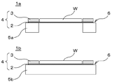
- FIG. 2 is a schematic view showing an example of the template assembly of the present invention.
- the workpiece W is also shown for explaining the positional relationship.
- the template assembly 1 a or the template assembly 1 b of the present invention includes a back pad 2 that holds the back surface of the workpiece W, and a retainer ring that is positioned on the back pad 2 and holds the edge portion of the workpiece W. 3 and a base ring 5 a or a base plate 5 b having an outer diameter larger than the outer diameter of the template 4.
- the template 4 is concentrically bonded to the base ring 5a or the base plate 5b.
- the base ring 5a or the base plate 5b has an outer diameter that is 10 mm or more larger than the outer diameter of the template 4 and has a surface roughness Ra ⁇ 6. 3 ⁇ m.
- the flatness of the retainer ring can be obtained more accurately than before, and as a result, it is possible to prevent variations in the flatness of the workpiece after polishing.
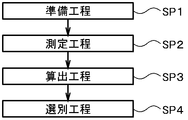
- FIG. 1 is a process diagram showing an example of a template assembly selection method of the present invention.
- a template 4 having a back pad 2 that holds the back surface of the work W and a retainer ring 3 that is positioned on the back pad 2 and holds an edge portion of the work W is used.
- a preparatory step (SP1 in FIG. 1) is performed for preparing the template assembly 1a or the template assembly 1b concentrically bonded to the base ring 5a or the base plate 5b having an outer diameter larger than the outer diameter.
- the retainer ring 3 can be designed with an inner diameter of usually 300.5 to 303 mm and an outer diameter of 320 to 400 mm.
- a base ring 5a or a base plate 5b having an outer diameter that is 10 mm or more larger than the outer diameter of the template 4 and a surface roughness Ra ⁇ 6.3 ⁇ m.
- the surface roughness can be Ra ⁇ 0 ⁇ m.
- the outer diameter of the base ring 5a or the base plate 5b can be designed to be 20 to 50 mm larger than the outer diameter of the retainer ring 3.
- the inner diameter of the base ring 5a can be arbitrarily set according to desired polishing characteristics.
- a measurement step (SP2 in FIG. 1) for measuring by destruction is performed.
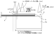
- a method using a laser displacement meter can be cited as shown in FIG.
- the height positions of the retainer ring 3 and the back pad 2 can be determined. It is preferable to measure the distribution in a lump.
- the flatness of the retainer ring 3 and the average step amount (pocket depth 7) between the retainer ring 3 and the back pad 2 can be measured together in the circumferential direction with high accuracy, high throughput, and non-destructiveness. it can.
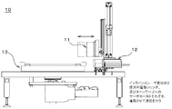
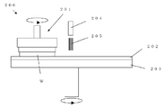
- the measurement process can be performed using the measurement unit 10 as shown in FIG.
- a non-contact laser displacement meter 11 is disposed on a cylinder 12 having a movable range in the radial direction of the template assembly, and a turntable 13 on which the template assembly can be placed with high accuracy is provided. It can be arranged so as to be directly under the laser displacement meter 11.
- the non-contact laser displacement meter 11 for example, a high precision type such as LJ-V7020 manufactured by KEYENCE can be used.
- the laser width of this non-contact laser displacement meter is 6 to 8 mm.
- the template assembly to be measured has a width of 40 mm as an example from the outer peripheral end of the base ring or the base plate to the inner peripheral end of the retainer ring.
- the sampling period of the non-contact laser displacement meter 11 is synchronized based on the encoder output for each of the rotation of the template assembly of the turntable 13 and the relative movement of the cylinder 12 in the radial direction of the template assembly.
- This can be programmed to enable continuous measurement.
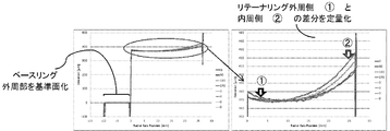
- the measurement start position may be on either the outer peripheral end side or the inner peripheral end side of the measurement range. However, as shown in FIG. This is preferable. Specifically, it is preferable that the radial position where the center of the laser width comes to the inner peripheral end of the retainer ring 3 is the measurement start position. As a result, the back pad 2 in the vicinity of the retainer ring 3 does not become a blind spot of measurement data, and measurement can be performed with high accuracy.
- the number of turns N required for the measurement can be arbitrarily set according to the size of the template assembly to be measured.
- the distance from the outer peripheral end of the base ring 5a (or base plate) to the inner peripheral end of the retainer ring 3 is b [mm]
- the overlap amount of the laser is c [mm]
- the number of turns N required for the whole area measurement can be represented by an integer that satisfies the inequality shown in the following equation (1). a + (N ⁇ 1) ⁇ (ac) ⁇ a / 2 + b (1)
- the laser scan width a is 6 [mm]
- the distance b from the outer peripheral end of the base ring 5a (or base plate) to the inner peripheral end of the retainer ring 3 is 40 [mm]
- the laser overlap amount c is 1 [ mm]
- the number of rotations N required for the whole area measurement can be obtained as 9 from Equation (1). If this number is set and the measurement start button is pressed, the measurement is automatically performed.
- the profile obtained by combining the data for the number of rotations N is leveled with the outer peripheral surface 6 of the base ring 5a (or base plate) as the reference plane, and for example, data as shown in FIG. 5 is output ( Distribution of height position).
- a calculation step (SP3 in FIG. 1) for calculating the flatness of the retainer ring 3 and the average step amount of the retainer ring 3 and the back pad 2 from the distribution of the measured height positions is performed.
- This calculation method is not particularly limited, and can be determined each time.
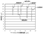
- the flatness of the retainer ring 3 is a difference between an average value of several mm on the inner peripheral side of the retainer ring 3 and an average value of several mm on the outer peripheral side of the retainer ring 3. It is possible to quantify the average value and standard deviation of the data for each circumferential direction. Further, the present invention is not limited to this calculation method. For example, the difference between the maximum value and the minimum value in the distribution of the height positions of the retainer ring can be set as the flatness.
- the average level difference between the retainer ring 3 and the back pad 2 is, for example, an average value of several millimeters on the inner peripheral side of the retainer ring 3 and a few millimeters on the inner side of the inner peripheral end of the retainer ring 3, that is, the back pad 2 portion.
- the difference between the average values can be taken and quantified by the average value and standard deviation of the data for each circumferential direction.
- the average step amount and flatness in each template assembly can be quantified. Moreover, individual template assemblies can be quantified with high accuracy and high throughput.
- a sorting step (SP4 in FIG. 1) for sorting the template assembly is performed based on the obtained flatness and the average step amount.
- the preparation step (SP1) a plurality of template assemblies are prepared, the measurement step (SP2) and the calculation step (SP3) are performed for each template assembly, and the flatness between the plurality of template assemblies is mutually reduced. It is preferable to select a template assembly having a difference of 5 ⁇ m or less and an average step difference of 5 ⁇ m or less. In this case, the difference in flatness and the difference in average step amount can be 0 ⁇ m or more.
- template assemblies having sufficiently small variations in flatness and average level difference between a plurality of template assemblies can be selected. Therefore, if the workpiece is polished using the template assembly selected in this way, it is possible to more reliably prevent the flatness of the workpiece after polishing from occurring, and to meet the demand for flatness tightness. I can respond.
- the flatness of the retainer ring is measured before mounting the polishing head, and the flatness and average
- the template assembly can be sorted based on the step amount. Therefore, when the workpiece is polished using the template assembly selected in this manner, it is possible to prevent the flatness of the workpiece after polishing from being varied. Furthermore, by performing the measurement process in a non-destructive manner, it is possible to prevent the retainer ring surface from being damaged and to prevent scratches from occurring on the polished workpiece.
- FIG. 6 it is composed of a surface plate 203 to which a polishing cloth 202 is attached, an abrasive supply mechanism 204, a polishing head 201 mounted with a template assembly selected as described above, and the like.
- the polishing machine 200 that is used can be used.
- the template assembly selected by the template assembly selection method of the present invention as described above is mounted on the polishing head 201, and the workpiece W is held. Then, the workpiece W is held by the polishing head 201, the polishing agent 205 is supplied onto the polishing cloth 202 from the polishing agent supply mechanism 204, and the surface of the workpiece W is rotated by rotating the surface plate 203 and the polishing head 201, respectively. It can grind
- the workpiece is polished using the template assembly selected by the template assembly selection method of the present invention, it is possible to prevent the flatness of the polished workpiece from being varied.
- Example 1 A polishing machine 200 provided with four polishing heads 201 as shown in FIG. 6 was prepared as a polishing machine. That is, the number of template assemblies attached to the polishing machine is four.
- the workpiece used was a semiconductor Si wafer having a diameter of 300 mm.
- a retainer ring made of a glass epoxy laminate having an outer diameter of 350 mm, an inner diameter of 301 mm, and a thickness of 700 ⁇ m (nominal value) is formed on a back pad made of a polyurethane resin having an outer diameter of 350 mm and a thickness of 0.5 mm (nominal value).
- the thing of the structure which carried out the thermocompression bonding using the heat sealing paste was prepared.
- the template used in Example 1 and the template used in Comparative Examples 1 to 3 described later were all manufactured in the same lot.
- a base ring made of ceramic having an outer diameter of 371 mm, an inner diameter of 310 mm, and a thickness of 20 mm was prepared as a base.
- the template assembly was prepared by adhering with a double-sided tape. A total of 20 similar template assemblies were prepared.
- non-contact laser displacement meter LJ-V7020 manufactured by KEYENCE
- KEYENCE used for the distribution of the retainer ring and the height position of the back pad when the outer peripheral surface of the base ring is used as a reference plane. Used and measured non-destructively.
- the laser scan width a of this non-contact laser displacement meter was 8 mm, and the laser overlap amount c was 0.5 mm. Since the inner diameter of the retainer ring is 301 mm and the outer diameter of the base ring is 371 mm, the distance b from the outer peripheral end of the base ring to the inner peripheral end of the retainer ring is 35 mm. Therefore, from the above equation (1), the number of laps required for the whole area measurement is set to 6. In addition, the sampling period was set to 1 °, and the data for 6 times were connected for each angle, and each was leveled using the outer peripheral surface of the base ring as a reference plane.
- the flatness of the retainer ring and the average step amount between the retainer ring and the back pad, that is, the pocket depth (PD) were calculated from the distribution of the measured height positions.
- the flatness Range ⁇ 5 ⁇ m and the P.P. D. Four were selected from 20 template assemblies with a standard of Range ⁇ 5 ⁇ m. That is, the variation in flatness between the four template assemblies is 5 ⁇ m or less, and P.I. D. Those having a variation of 5 ⁇ m or less were extracted. The time required for measurement and selection at this time was measured and shown in Table 1.
- the four template assemblies selected as described above are respectively mounted on a polishing head 201 of a polishing machine 200 as shown in FIG. 6, and a total of 100 workpieces that are semiconductor Si wafers having a diameter of 300 mm are continuously polished. did.
- Example 1 the workpiece was polished in the same manner as in Example 1 except that the template assembly selected in Comparative Example 1 was used. Then, the flatness and scratch of the workpiece after polishing were measured in the same manner as in Example 1, and the results are shown in Table 2. For verification, in the template assembly after polishing the workpiece, D. The flatness was measured and the results are shown in Table 1.
- P. of this template assembly. D. was manually measured using a JA-205 manufactured by PEACOCK, a low-pressure micrometer. Specifically, the difference value obtained by measuring the thickness of the inner periphery of the retainer ring and the thickness of the back pad in the vicinity of the retainer ring in the same radial direction as the measurement location is calculated, and the average value of 8 points in each 45 ° plane is calculated.
- P. D. It was. P. D. Four were selected from 20 template assemblies with a standard of Range ⁇ 5 ⁇ m. The time required for measurement and selection at this time was measured and shown in Table 1.
- Example 1 the workpiece was polished in the same manner as in Example 1 except that the template assembly selected in Comparative Example 2 was used. Then, the flatness and scratch of the workpiece after polishing were measured in the same manner as in Example 1, and the results are shown in Table 2. Further, the flatness of the template assembly after the workpiece was polished was measured, and the results are shown in Table 1.
- P. D. was measured in the same manner as in Comparative Example 2.
- For flatness as a contact profiler, manually measure 8 in-plane lines using Mitutoyo's SJ-400, the average value of 0.5 to 1.5 mm from the outer periphery of the retainer ring, and within the retainer ring The difference between the average values of 0.5 to 1.5 mm from the peripheral edge was calculated at 8 points in each plane at 45 °, and the average value was defined as flatness.
- Example 2 the workpiece was polished in the same manner as in Example 1 except that the template assembly selected in Comparative Example 3 was used. Then, the flatness and scratch of the workpiece after polishing were measured in the same manner as in Example 1, and the results are shown in Table 2.
- Comparative Examples 2 and 3 require time for manual measurement and measurement / sorting time.
- both parameters could be measured and selected with high throughput.
- Examples 2 to 4, Comparative Examples 4 to 5 First, as a template, a retainer ring made of a glass epoxy laminate having an outer diameter of 350 mm, an inner diameter of 301 mm, and a thickness of 700 ⁇ m (nominal value) is placed on a back pad made of a polyurethane resin having an outer diameter of 350 mm and a thickness of 0.5 mm (nominal value). A heat-bonding paste was used and a retainer ring with a flatness of 15 ⁇ m was prepared.
- each of the templates is 20 mm (Example 2), 15 mm (Example 3), 10 mm (Example 4), 7.5 mm (Comparative Example 4), and 5 mm (Comparative Example 5).
- Five large base rings were prepared.
- those having a surface roughness Ra of 6.3 ⁇ m were used.
- Examples 5 to 7, Comparative Examples 6 to 7 First, the same templates as those prepared in Examples 2 to 4 and Comparative Examples 4 to 5 were prepared. Further, the surface roughness Ra is 10.5 ⁇ m (Comparative Example 6), 8.7 ⁇ m (Comparative Example 7), 6.3 ⁇ m (Example 5), 5, 2 ⁇ m (Example 6), 3.1 ⁇ m (Example 7). 5 types of base rings were prepared. A base ring having an outer diameter 10 mm larger than the outer diameter of the template was used.
- the present invention is not limited to the above embodiment.
- the above-described embodiment is an exemplification, and the present invention has any configuration that has substantially the same configuration as the technical idea described in the claims of the present invention and that exhibits the same effects. Are included in the technical scope.
Landscapes
- Engineering & Computer Science (AREA)
- Physics & Mathematics (AREA)
- General Physics & Mathematics (AREA)
- Mechanical Engineering (AREA)
- Condensed Matter Physics & Semiconductors (AREA)
- Manufacturing & Machinery (AREA)
- Computer Hardware Design (AREA)
- Microelectronics & Electronic Packaging (AREA)
- Power Engineering (AREA)
- Finish Polishing, Edge Sharpening, And Grinding By Specific Grinding Devices (AREA)
- Mechanical Treatment Of Semiconductor (AREA)
- Length Measuring Devices By Optical Means (AREA)
Priority Applications (5)
| Application Number | Priority Date | Filing Date | Title |
|---|---|---|---|
| CN201780026381.2A CN109070308B (zh) | 2016-05-13 | 2017-03-14 | 模板组件的选别方法及工件的研磨方法以及模板组件 |
| SG11201809720VA SG11201809720VA (en) | 2016-05-13 | 2017-03-14 | Method for selecting template assembly, method for polishing workpiece, and template assembly |
| KR1020187031793A KR102337600B1 (ko) | 2016-05-13 | 2017-03-14 | 템플레이트 어셈블리의 선별방법과 워크의 연마방법 및 템플레이트 어셈블리 |
| US16/094,085 US11731236B2 (en) | 2016-05-13 | 2017-03-14 | Method for selecting template assembly, method for polishing workpiece, and template assembly |
| DE112017002055.7T DE112017002055B4 (de) | 2016-05-13 | 2017-03-14 | Verfahren zum Auswählen einer Schablonenanordnung, Verfahren zum Polieren eines Werkstücks und Schablonenanordnung |
Applications Claiming Priority (2)
| Application Number | Priority Date | Filing Date | Title |
|---|---|---|---|
| JP2016-096794 | 2016-05-13 | ||
| JP2016096794A JP6508123B2 (ja) | 2016-05-13 | 2016-05-13 | テンプレートアセンブリの選別方法及びワークの研磨方法並びにテンプレートアセンブリ |
Publications (1)
| Publication Number | Publication Date |
|---|---|
| WO2017195460A1 true WO2017195460A1 (ja) | 2017-11-16 |
Family
ID=60266919
Family Applications (1)
| Application Number | Title | Priority Date | Filing Date |
|---|---|---|---|
| PCT/JP2017/010203 WO2017195460A1 (ja) | 2016-05-13 | 2017-03-14 | テンプレートアセンブリの選別方法及びワークの研磨方法並びにテンプレートアセンブリ |
Country Status (8)
Families Citing this family (4)
| Publication number | Priority date | Publication date | Assignee | Title |
|---|---|---|---|---|
| JP6508123B2 (ja) * | 2016-05-13 | 2019-05-08 | 信越半導体株式会社 | テンプレートアセンブリの選別方法及びワークの研磨方法並びにテンプレートアセンブリ |
| JP7070502B2 (ja) * | 2019-05-16 | 2022-05-18 | 信越半導体株式会社 | 測定装置および研磨ヘッドの選定方法ならびにウエーハの研磨方法 |
| JP7388324B2 (ja) * | 2019-12-05 | 2023-11-29 | 株式会社Sumco | ウェーハの片面研磨方法、ウェーハの製造方法、およびウェーハの片面研磨装置 |
| CN114406896A (zh) * | 2022-01-25 | 2022-04-29 | 上海江丰平芯电子科技有限公司 | 一种快速检测寿命的保持环及其使用方法 |
Citations (6)
| Publication number | Priority date | Publication date | Assignee | Title |
|---|---|---|---|---|
| JP2009260142A (ja) * | 2008-04-18 | 2009-11-05 | Panasonic Corp | ウェハ研磨装置及びウェハ研磨方法 |
| JP2010247254A (ja) * | 2009-04-13 | 2010-11-04 | Shin Etsu Handotai Co Ltd | 研磨ヘッドの製造方法及び研磨装置 |
| JP2014184511A (ja) * | 2013-03-22 | 2014-10-02 | Shin Etsu Handotai Co Ltd | テンプレートアセンブリ及びテンプレートアセンブリの製造方法 |
| JP2014233815A (ja) * | 2013-06-04 | 2014-12-15 | 信越半導体株式会社 | 研磨ヘッドの製造方法及び研磨装置 |
| JP2015196211A (ja) * | 2014-03-31 | 2015-11-09 | 株式会社荏原製作所 | 研磨装置及び研磨方法 |
| JP2017087328A (ja) * | 2015-11-06 | 2017-05-25 | 信越半導体株式会社 | ウェーハの研磨方法及び研磨装置 |
Family Cites Families (22)
| Publication number | Priority date | Publication date | Assignee | Title |
|---|---|---|---|---|
| JP2632738B2 (ja) * | 1990-04-27 | 1997-07-23 | 信越半導体 株式会社 | パッキングパッド、および半導体ウェーハの研磨方法 |
| JP2000296461A (ja) * | 1999-04-13 | 2000-10-24 | Speedfam-Ipec Co Ltd | バッキングパッド構造体 |
| DE60138338D1 (de) * | 2000-06-20 | 2009-05-28 | Kurita Water Ind Ltd | Brennstoffzellenstromversorgungssystem und Betriebsverfahren |
| US6709981B2 (en) * | 2000-08-16 | 2004-03-23 | Memc Electronic Materials, Inc. | Method and apparatus for processing a semiconductor wafer using novel final polishing method |
| JP3838341B2 (ja) * | 2001-09-14 | 2006-10-25 | 信越半導体株式会社 | ウェーハの形状評価方法及びウェーハ並びにウェーハの選別方法 |
| US8268114B2 (en) * | 2001-09-28 | 2012-09-18 | Shin-Etsu Handotai Co., Ltd. | Workpiece holder for polishing, workpiece polishing apparatus and polishing method |
| TW545580U (en) * | 2002-06-07 | 2003-08-01 | Nanya Technology Corp | CMP device of measuring apparatus with a notched size for measuring the guide ring of wafer edge |
| JP2007287787A (ja) | 2006-04-13 | 2007-11-01 | Elpida Memory Inc | 半導体装置の製造方法及び装置 |
| JP5157148B2 (ja) * | 2006-12-11 | 2013-03-06 | ダイキン工業株式会社 | 圧縮機 |
| US20080299882A1 (en) * | 2007-05-30 | 2008-12-04 | Nippon Seimitsu Denshi Co., Ltd. | Retainer-ring of cmp (chemical mechanical polishing) machine |
| JP2008302464A (ja) * | 2007-06-07 | 2008-12-18 | Renesas Technology Corp | 研磨装置およびそれを用いた半導体装置の製造方法 |
| KR20090124017A (ko) * | 2008-05-29 | 2009-12-03 | 주식회사 동부하이텍 | Cmp 장치의 리테이너링 |
| SG192518A1 (en) | 2008-07-31 | 2013-08-30 | Shinetsu Handotai Kk | Wafer polishing method |
| JP5504901B2 (ja) * | 2010-01-13 | 2014-05-28 | 株式会社Sumco | 研磨パッドの形状修正方法 |
| JP5303491B2 (ja) * | 2010-02-19 | 2013-10-02 | 信越半導体株式会社 | 研磨ヘッド及び研磨装置 |
| JP2013004928A (ja) * | 2011-06-21 | 2013-01-07 | Shin Etsu Handotai Co Ltd | 研磨ヘッド、研磨装置及びワークの研磨方法 |
| KR20140048894A (ko) * | 2011-06-29 | 2014-04-24 | 신에쯔 한도타이 가부시키가이샤 | 연마 헤드 및 연마 장치 |
| JP5807580B2 (ja) * | 2012-02-15 | 2015-11-10 | 信越半導体株式会社 | 研磨ヘッド及び研磨装置 |
| JP5976522B2 (ja) | 2012-05-31 | 2016-08-23 | 株式会社荏原製作所 | 研磨装置および研磨方法 |
| JP2015218440A (ja) | 2014-05-14 | 2015-12-07 | 住友林業株式会社 | 複数階を有する建物内の壁構造、および建物 |
| JP6393127B2 (ja) * | 2014-09-10 | 2018-09-19 | 丸石産業株式会社 | 保持パッド |
| JP6508123B2 (ja) * | 2016-05-13 | 2019-05-08 | 信越半導体株式会社 | テンプレートアセンブリの選別方法及びワークの研磨方法並びにテンプレートアセンブリ |
-
2016
- 2016-05-13 JP JP2016096794A patent/JP6508123B2/ja active Active
-
2017
- 2017-03-14 WO PCT/JP2017/010203 patent/WO2017195460A1/ja active Application Filing
- 2017-03-14 DE DE112017002055.7T patent/DE112017002055B4/de active Active
- 2017-03-14 CN CN201780026381.2A patent/CN109070308B/zh active Active
- 2017-03-14 US US16/094,085 patent/US11731236B2/en active Active
- 2017-03-14 SG SG11201809720VA patent/SG11201809720VA/en unknown
- 2017-03-14 KR KR1020187031793A patent/KR102337600B1/ko active Active
- 2017-04-06 TW TW106111464A patent/TWI722164B/zh active
Patent Citations (6)
| Publication number | Priority date | Publication date | Assignee | Title |
|---|---|---|---|---|
| JP2009260142A (ja) * | 2008-04-18 | 2009-11-05 | Panasonic Corp | ウェハ研磨装置及びウェハ研磨方法 |
| JP2010247254A (ja) * | 2009-04-13 | 2010-11-04 | Shin Etsu Handotai Co Ltd | 研磨ヘッドの製造方法及び研磨装置 |
| JP2014184511A (ja) * | 2013-03-22 | 2014-10-02 | Shin Etsu Handotai Co Ltd | テンプレートアセンブリ及びテンプレートアセンブリの製造方法 |
| JP2014233815A (ja) * | 2013-06-04 | 2014-12-15 | 信越半導体株式会社 | 研磨ヘッドの製造方法及び研磨装置 |
| JP2015196211A (ja) * | 2014-03-31 | 2015-11-09 | 株式会社荏原製作所 | 研磨装置及び研磨方法 |
| JP2017087328A (ja) * | 2015-11-06 | 2017-05-25 | 信越半導体株式会社 | ウェーハの研磨方法及び研磨装置 |
Also Published As
| Publication number | Publication date |
|---|---|
| US11731236B2 (en) | 2023-08-22 |
| DE112017002055B4 (de) | 2024-06-06 |
| DE112017002055T5 (de) | 2018-12-27 |
| US20190126431A1 (en) | 2019-05-02 |
| TW201805115A (zh) | 2018-02-16 |
| KR20190002506A (ko) | 2019-01-08 |
| TWI722164B (zh) | 2021-03-21 |
| CN109070308B (zh) | 2021-01-12 |
| SG11201809720VA (en) | 2018-12-28 |
| KR102337600B1 (ko) | 2021-12-10 |
| JP2017202556A (ja) | 2017-11-16 |
| CN109070308A (zh) | 2018-12-21 |
| JP6508123B2 (ja) | 2019-05-08 |
Similar Documents
| Publication | Publication Date | Title |
|---|---|---|
| WO2017195460A1 (ja) | テンプレートアセンブリの選別方法及びワークの研磨方法並びにテンプレートアセンブリ | |
| TWI546155B (zh) | Workpiece on both sides of the grinding device and two sides grinding method | |
| JP5847789B2 (ja) | 両面研磨装置用キャリアの製造方法およびウエーハの両面研磨方法 | |
| US6975960B2 (en) | Method for evaluating wafer configuration, wafer, and wafer sorting method | |
| JP6397790B2 (ja) | ウェーハ位置決め検出装置、方法およびプログラム | |
| US20170069502A1 (en) | Manufacturing method of carrier for double-side polishing apparatus, carrier for double-side polishing apparatus, and double-side polishing method | |
| JP2014151418A (ja) | オリエンテーションフラット等切り欠き部を有する、結晶材料から成るウエハの周縁を、研磨テープを使用して研磨することにより円形ウエハを製造する方法 | |
| JP6099960B2 (ja) | ウェーハの面取り加工方法およびウェーハの面取り装置 | |
| TWI577501B (zh) | Template assembly and template component manufacturing method | |
| JP7068096B2 (ja) | 被加工物の研削方法 | |
| TWI718542B (zh) | 工件的兩面研磨裝置及兩面研磨方法 | |
| JP6539467B2 (ja) | 研削加工装置 | |
| JP6844530B2 (ja) | ワークの両面研磨装置および両面研磨方法 | |
| JP7696316B2 (ja) | 研磨方法および研磨装置 | |
| JP7046670B2 (ja) | 面取り加工システム及びそれに用いられるツルーイング装置 | |
| WO2017061077A1 (ja) | テンプレートの測定方法及び評価方法 | |
| WO2025134503A1 (ja) | 両面研磨装置用キャリアプレートの製造方法、ワークの両面研磨方法、及び両面研磨装置用キャリアプレート | |
| KR20250061622A (ko) | 워크 가공 장치 | |
| Suzuki et al. | PRECISION GRINDING OF ASPHERICAL SURFACE: ACCURACY IMPROVING BY ON-MACHINE MEASUREMENT | |
| JP2022088476A (ja) | 面取り加工システム | |
| Aramaki-aoba | H. SUZUKI, N. WAJIMA, MS SEPASY ZAHMATY, T. KURIYAGAWA, K. SYOJI | |
| JPH05208327A (ja) | スローアウェイチップの製造方法 |
Legal Events
| Date | Code | Title | Description |
|---|---|---|---|
| ENP | Entry into the national phase |
Ref document number: 20187031793 Country of ref document: KR Kind code of ref document: A |
|
| 121 | Ep: the epo has been informed by wipo that ep was designated in this application |
Ref document number: 17795821 Country of ref document: EP Kind code of ref document: A1 |
|
| 122 | Ep: pct application non-entry in european phase |
Ref document number: 17795821 Country of ref document: EP Kind code of ref document: A1 |