WO2017195432A1 - 操作装置、該操作装置を用いた車両用シフト装置 - Google Patents
操作装置、該操作装置を用いた車両用シフト装置 Download PDFInfo
- Publication number
- WO2017195432A1 WO2017195432A1 PCT/JP2017/007131 JP2017007131W WO2017195432A1 WO 2017195432 A1 WO2017195432 A1 WO 2017195432A1 JP 2017007131 W JP2017007131 W JP 2017007131W WO 2017195432 A1 WO2017195432 A1 WO 2017195432A1
- Authority
- WO
- WIPO (PCT)
- Prior art keywords
- magnetic body
- movable member
- permanent magnet
- shift
- base portion
- Prior art date
- Legal status (The legal status is an assumption and is not a legal conclusion. Google has not performed a legal analysis and makes no representation as to the accuracy of the status listed.)
- Ceased
Links
Images






Classifications
-
- B—PERFORMING OPERATIONS; TRANSPORTING
- B60—VEHICLES IN GENERAL
- B60K—ARRANGEMENT OR MOUNTING OF PROPULSION UNITS OR OF TRANSMISSIONS IN VEHICLES; ARRANGEMENT OR MOUNTING OF PLURAL DIVERSE PRIME-MOVERS IN VEHICLES; AUXILIARY DRIVES FOR VEHICLES; INSTRUMENTATION OR DASHBOARDS FOR VEHICLES; ARRANGEMENTS IN CONNECTION WITH COOLING, AIR INTAKE, GAS EXHAUST OR FUEL SUPPLY OF PROPULSION UNITS IN VEHICLES
- B60K20/00—Arrangement or mounting of change-speed gearing control devices in vehicles
- B60K20/02—Arrangement or mounting of change-speed gearing control devices in vehicles of initiating means
-
- G—PHYSICS
- G05—CONTROLLING; REGULATING
- G05G—CONTROL DEVICES OR SYSTEMS INSOFAR AS CHARACTERISED BY MECHANICAL FEATURES ONLY
- G05G5/00—Means for preventing, limiting or returning the movements of parts of a control mechanism, e.g. locking controlling member
- G05G5/03—Means for enhancing the operator's awareness of arrival of the controlling member at a command or datum position; Providing feel, e.g. means for creating a counterforce
Definitions
- the present invention relates to an operating device used for an operating body that performs an operation by tilting, and particularly relates to an operating device using a magnetic material and a vehicle shift device using the operating device.
- an operation body that performs an operation while being tilted is often used for a remote controller of various electronic devices such as a television and a video, an input device of a game machine, an operation device for a vehicle, and the like.
- an operation device of a type that performs a tilting operation by holding an operation body is used.
- a moderation feeling when the operation body is tilted to perform a switching operation.
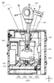
- Patent Document 1 proposes a shift operation device 900 for an automatic transmission as shown in FIG.
- FIG. 16 is an enlarged longitudinal sectional view showing a state when the shift lever 901 is in the N range (neutral range) in the shift operation device 900 for the automatic transmission of the conventional example.
- a shift operation device 900 for an automatic transmission shown in FIG. 16 is capable of swinging a shift lever 901 that has a knob 902 fixed thereto and swings, a holder 903 that is fixed to the shift lever 901 and swings, and a shift lever 901.
- the automatic transmission shift operating device 900 has a first range 905 as a swing axis, a P range (parking range), an R range (reverse range), an N range (neutral range), and The shift lever 901 can swing at each position in the D range (drive range). At that time, the shift lever 901 is moved to each position (P range) using the moderation spring 909 and the moderation body 910 provided in the lower body portion 903c of the holder 903 and the moderation groove 904a formed in the inner bottom of the case 904. , R range, N range, D range), or automatically returns the shift lever 901. Specifically, as shown in FIG.
- the moderation groove 904a supports the first moderation groove 904b that supports the shift lever 901 in the P range, the second moderation groove 904c that supports the R range, and the N range.
- a third moderation groove 904d and a fourth moderation groove 904e supported in the D range are formed in the front-rear direction, and the moderation body 910 biased by the moderation spring 909 slides along the moderation groove 904a. It is supposed to be.
- the shift operation device 900 for an automatic transmission configured as described above has a moderation groove 904a (904b, 904c, 904d, 904d) provided corresponding to each position (P range, R range, N range, D range).
- a moderation feeling is given to the shift lever 901.
- the moderation body 910 uses a sliding mechanism that slides on the moderation groove 904a in order to provide this moderation feeling. Therefore, when the shift lever 901 is repeatedly swung, the moderation groove There is a problem that the durability of the sliding mechanism is lowered, such as wear of 904a and the moderation spring 909, deterioration of the spring property of the moderation spring 909, and rattling between the moderation spring 909 and the moderation body 910.
- An object of the present invention is to solve the above-described problems, and to provide an operation device having a moderation feeling and excellent durability and a vehicle shift device using the operation device.
- the operating device of the present invention includes an operating member that can be tilted in response to an operator's operation, and a support that supports the operating member on a tilting shaft so that the tilting operation is possible.
- An operating device having a plurality of positions where the operating member is positioned in response to a tilting operation from a reference position by the operator, wherein the operating member is disposed on one side where the operating member tilts
- a first movable member and a second movable member that are tilted in conjunction with the first movable member, a first magnetic body provided in the first movable member, a second magnetic body provided in the second movable member, A first permanent magnet supported by a support, and a third movable member that tilts in conjunction with the operation member across the tilting shaft on the other direction side where the operation member tilts.
- a fourth movable member, and a third magnet provided in the third movable member A body, a fourth magnetic body provided in the fourth movable member, and a second permanent magnet supported by the support, and when the operating member is at the reference position, The first magnetic body and the second magnetic body are brought close to each other and disposed on one side of the first permanent magnet, and the first magnetic body, the second magnetic body, and the first permanent magnet are attracted to each other.
- the operation member is held at the reference position, the third magnetic body and the fourth magnetic body are spaced apart and disposed on one side of the second permanent magnet, and the operation member is
- the first magnetic body is first separated from the first permanent magnet with the tilting operation of the first movable member.
- the third movable member with the tilting operation The magnetic body is held close to the second permanent magnet, and then the second magnetic body is separated from the first permanent magnet with the tilting operation of the second movable member, and the fourth movable member According to the tilting operation, the fourth magnetic body is held close to the second permanent magnet.
- the operating device of the present invention first changes from the strong attraction state of the first magnetic body and the first permanent magnet to the weak attraction state when switching from the reference position to the next position, and the third magnetic The body and the second permanent magnet are attracted to each other and are held at the next position.
- the second magnetic body and the first permanent magnet change from a strong attraction state to a weak attraction state
- the fourth magnetic body and the second permanent magnet It becomes a strong suction state and is held at the next position.
- a feeling of moderation can be given to the operator, and the operation member is held at each moved position.
- the operating member includes a columnar operating shaft and a base portion extending in a plane through which the shaft center of the operating shaft passes, and the base portion is accompanied with the tilting operation.
- the base portion includes a first pressing portion capable of contacting the first movable member and a second pressing portion capable of contacting the second movable member, and the operation member is provided on the base portion.
- the distance between the first movable member and the first pressing portion is opposed to each other so that the distance between the second movable member and the second pressing portion is smaller. It is characterized by being.
- the first pressing member presses the first movable member facing the first movable member, and the first magnetic body provided in the first movable member tilts.
- the second movable member presses the second movable member facing the second movable member.
- the second magnetic body provided in the is tilted so that the second magnetic body and the first permanent magnet are separated from each other. Accordingly, the first magnetic body and the first permanent magnet can be easily separated from each other, and the second magnetic body and the first permanent magnet can be easily separated from each other. Therefore, an operation device having a moderation feeling can be easily manufactured.
- the base portion is in contact with the third movable member and a first restricting portion that restricts the movement of the third movable member, and the fourth movable member.
- the restricting portions (the first restricting portion and the second restricting portion) of the base portion are tilted so that the third movable member and the first movable member are tilted.
- the four movable members are tilted, and the third magnetic body provided in the third movable member and the fourth magnetic body provided in the fourth movable member are tilted.
- the third magnetic body and the second permanent magnet are in a strong attraction state and are held at the next position, and then the fourth magnetic body and the second permanent magnet are in a strong attraction state and are held at the next position. Will come to be.
- the third magnetic body and the second permanent magnet can be easily attracted, and the fourth magnetic body and the second permanent magnet can be easily attracted.
- the operating member can be easily held at each position.
- the base portion includes a restricting portion that abuts the third movable member and restricts the movement of the third movable member, and the fourth movable member is the first movable member. 2 It is characterized by being formed integrally with the movable member.
- the third movable member is tilted by the tilting operation of the restricting portion of the base portion, and the third movable member is provided.
- the third magnetic body is tilted to bring the third magnetic body and the second permanent magnet into a strong attracting state and is held at the next position.
- the second pressing member of the base portion presses the second movable member facing the fourth movable member formed integrally with the second movable member.
- the fourth magnetic body provided in the fourth movable member is tilted, and the fourth magnetic body and the second permanent magnet are in a strong attracting state and are held at the next position.
- the third magnetic body and the second permanent magnet can be easily attracted, and the fourth magnetic body and the second permanent magnet can be easily attracted.
- the operating member can be easily held at each position.
- a vehicle shift device the operation device according to any of the above, a control unit that receives a signal from the operation device and transmits a signal to a vehicle-side device, and the operation member of the operation device And a position detecting means for detecting the plurality of positions where the operation member is positioned.
- the operating device capable of operating to each position can be suitably applied to the shift arrangement (shift pattern) of the vehicle shift device.
- a shift operation with a sense of moderation can be performed, and compared with the conventional example, since there is no sliding mechanism in the portion that causes a sense of moderation, the durability is excellent. .
- the operating device of the present invention first changes from a strong attraction state of the first magnetic body and the first permanent magnet to a weak attraction state when switching from the reference position to the next position, and the third magnetic body and the second permanent state.
- the magnet is in a strong attractive state and is held in the next position.
- the second magnetic body and the first permanent magnet change from a strong attraction state to a weak attraction state
- the fourth magnetic body and the second permanent magnet It becomes a strong suction state and is held at the next position.
- a feeling of moderation can be given to the operator, and the operation member is held at each moved position.
- an operation device that can operate each position can be suitably applied to the shift arrangement (shift pattern) of the vehicle shift device.
- a shift operation with a sense of moderation can be performed, and compared with the conventional example, since there is no sliding mechanism in the portion that causes a sense of moderation, the durability is excellent. .
- FIG. 2A is a view for explaining a vehicle shift device using the operation device according to the first embodiment of the present invention
- FIG. 2A is a front view seen from the Y2 side shown in FIG. b) is a side view seen from the X1 side shown in FIG.
- FIG. 4A is a diagram specifically explaining the operation of the vehicle shift device using the operation device according to the first embodiment of the present invention
- FIG. 4A is a plan view showing the arrangement of the shift of the vehicle.
- FIG. 7A and 7B are diagrams illustrating the operation device according to the first embodiment of the present invention, in which FIG. 7A is a front view as viewed from the Y2 side illustrated in FIG. 6, and FIG. 7B is illustrated in FIG. It is the rear view seen from the Y1 side.
- FIG. 7A is a front view as viewed from the Y2 side illustrated in FIG. 6, and FIG. 7B is illustrated in FIG. It is the rear view seen from the Y1 side.
- FIG. 7A is a front view as viewed from the Y2 side illustrated in FIG. 6, and FIG. 7B is illustrated in FIG. It is the rear view seen from the Y1 side.
- FIG. 7A is a front view as viewed from the Y2 side illustrated in FIG. 6, and FIG. 7B is illustrated in FIG. It is the rear view seen from the Y1 side.
- FIG. 7A is a front view as viewed from the Y2 side illustrated in FIG. 6, and FIG. 7B is illustrated in FIG. It is
- FIG. 8A is a diagram illustrating the operating device according to the first embodiment of the present invention
- FIG. 8A is a perspective view in which the first movable member and the first magnetic body shown in FIG. 6 are omitted
- FIG. ) Is a perspective view in which the second movable member and the second magnetic body shown in FIG.
- FIG. 9A is a perspective view of the operation member
- FIG. 9B is a diagram illustrating the operation member of the operation device according to the first embodiment of the present invention. It is a front view of the operation member seen from the Y2 side.
- Fig.10 (a) is the perspective view which looked at the operation member shown to Fig.9 (a) from the reverse side
- 10 (b) is a rear view of the operation member when FIG. 10 (a) is viewed from the Y1 side.
- Fig.11 (a) is an upper perspective view of the frame of a support body
- FIG.11 (b) is a support body. It is a downward perspective view of this frame.
- FIGS. 12A and 12B are schematic diagrams for explaining the operation of the controller device according to the first embodiment of the present invention, in which FIG. 12A is a diagram of the state of the reference position, and FIG. FIG. 12C is a diagram in a state of being tilted in the other direction of the first direction than in FIG. 12B.
- FIGS. 13A and 13B are schematic diagrams for explaining the operation of the controller device according to the first embodiment of the present invention, in which FIG. 13A is a diagram of the state of the reference position, and FIG. FIG. 13C is a diagram in a state of being tilted in one direction in the first direction further than that in FIG. 13B.
- FIG. 13A is a diagram of the state of the reference position
- FIG. 13C is a diagram in a state of being tilted in one direction in the first direction further than that in FIG. 13B.
- FIG. 14A is a schematic diagram for explaining Modification Example 1 of the operating device according to the first embodiment of the present invention.
- FIG. 14A is a side view of a main part of the operating device, and FIG. It is the side view which abbreviate
- FIG. 15A is a schematic diagram illustrating a modification of the operating device according to the first embodiment of the present invention
- FIG. 15A is a side view of Modification 3 and Modification 4, and
- FIG. It is a side view of the modification 5 and the modification 6.
- N range neutral range
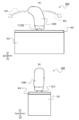
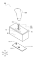
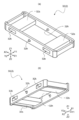
- FIG. 1 is a perspective view illustrating a vehicle shift device 500 using an operation device 100 according to the first embodiment of the present invention.
- FIG. 2 is a diagram for explaining a vehicle shift device 500 using the operation device 100 according to the first embodiment of the present invention, and FIG. 2A is a front view as seen from the Y2 side shown in FIG.
- FIG. 2B is a side view seen from the X1 side shown in FIG.
- FIG. 3 is an exploded perspective view illustrating the vehicle shift device 500 using the operation device 100 according to the first embodiment of the present invention.
- the vehicle shift device 500 using the operation device 100 according to the first embodiment of the present invention has a box-like appearance as shown in FIGS. 1 and 2, and is held by an operator as shown in FIG.
- Position detecting means (not shown) for detecting a plurality of positions where the operation member 1 of the apparatus 100 is located is configured.
- the vehicle shift device 500 includes a case K2 that houses the operating device 100 and a cover K5 that covers an open portion on the upper side of the case K2 (vehicle shift). And the wiring board 19 that is housed in the case K2 of the operating device 100 and on which the control unit 50C is mounted.
- the vehicle shift device 500 is mounted on a vehicle and used for a vehicle shift operation that can perform a tilt operation in the front-rear direction (tilt direction KD, X direction shown in FIG. 2A).
- the shift knob 50N of the vehicle shift device 500 is formed in an elongated shape so as to be easily gripped by an operator as shown in FIGS. 1 to 3, and as shown in FIGS.
- the operation member 1 is engaged with the operation member 1 so as to cover the operation shaft 1j (see FIG. 3).
- the shift knob 50N is manufactured by injection molding using a synthetic resin such as ABS resin (ABS, acrylonitrile butadiene styrene copolymer).
- control unit 50C of the vehicle shift device 500 is configured using an integrated circuit (IC, IntegratedIntegrCircuit), and is mounted on the wiring board 19 (see FIG. 3) housed in the box-shaped case K2. Yes.
- the control unit 50C is connected to the vehicle-side device via a connector (not shown), and transmits a position information signal that has been operated in response to the tilting operation of the shift knob 50N to the vehicle-side device.
- the vehicle Upon receiving this position information signal, the vehicle performs an operation corresponding to the shift pattern and displays the position of the shift knob 50N in the shift pattern on a display unit provided on the instrument panel or the like.
- the position detection means of the vehicle shift device 500 is a so-called rotary variable resistor configured by a substrate on which a resistor pattern is formed and a slider that slidably contacts the resistance pattern. And a position detector for detecting a plurality of positions in the tilting operation in the tilting direction KD. And this position detector is accommodated in the box-shaped case K2. As will be described later, the position detector is engaged with a tilt shaft 12e (see FIG. 6 described later) of the support 2 to detect the rotation angle of the tilt shaft 12e.
- the position detecting means has a signal processing unit 52S for processing a signal from the position detector, and the signal processing unit 52S is mounted on the wiring board 19 as shown in FIG.
- the signal processing unit 52S is connected to the position detector via a flexible printed circuit board (FPC, Flexible printed circuit) (not shown). Then, the signal processing unit 52S calculates the rotation angle of the tilt shaft 12e based on the signal from the position detector, and detects the movement of the operation member 1 in the tilt direction KD from the rotation angle.
- FPC Flexible printed circuit
- the case K2 of the vehicle shift device 500 is manufactured by injection molding a synthetic resin material such as polybutylene terephthalate (PBT), and has a rectangular shape with an opening having an open upper surface. It is formed in a box shape.
- PBT polybutylene terephthalate
- the cover K5 of the vehicle shift device 500 is manufactured by injection molding a synthetic resin material such as polybutylene terephthalate (PBT), as in the case K2. As shown in FIG. It is formed so as to cover the opening on the upper side of the case K2. Although not shown in detail, the cover K5 is engaged with the case K2.
- PBT polybutylene terephthalate
- a circular through hole K5h is formed in the center portion of the cover K5, and the operation shaft 1j of the operation member 1 is inserted into the through hole K5h, so that the operation shaft 1j is It is exposed on the upper surface side of the cover K5. Accordingly, the operation shaft 1j of the operation member 1 of the operation device 100 and the shift knob 50N of the vehicle shift device 500 can be engaged.
- the wiring board 19 of the vehicle shift device 500 uses a general single-sided printed wiring board (PWB, printed wiring board), and as described above, the control unit 50C and the signal processing unit 52S are mounted. (See FIG. 3). Although not shown, the wiring board 19 is connected to a flexible printed circuit board (FPC) for electrical connection between the position detector and the signal processing unit 52S and connected to an external device. The connector for is installed.
- PWB printed wiring board
- FPC flexible printed circuit board
- FIG. 4 is a diagram for specifically explaining the operation of the vehicle shift device 500 using the operation device 100 according to the first embodiment of the present invention.
- FIG. FIG. 4B is a plan view showing the position position of the shift knob 50N.
- the shift pattern shown in FIG. 4A is displayed on a display unit provided on the above-described instrument panel or the like.
- the position position shown in FIG. 4B is a schematic view of the position where the operation member 1 is moved by operating the shift knob 50N (operation member 1).
- the shift pattern shown in FIG. 4A is an example in the vehicle shift device 500 to which the operation device 100 is applied, and is not limited to this shift pattern.
- the vehicle shift device 500 according to the first embodiment of the present invention is applied to an electronically controlled vehicle, not a mechanically controlled vehicle in which the shift knob 50N is directly connected to the transmission. Therefore, the vehicle shift operation is performed only by the information signal of the shift position transmitted from the operation device 100. This shift position is shown in the shift pattern displayed on the display part provided in the instrument panel etc. which were mentioned above.
- the shift knob 50N (operation member 1) is located at the reference position PP shown in FIG. 4B and the shift position is located in the neutral mode “N” shown in FIG. 4A, the shift knob 50N is tilted KD.
- the shift position is moved to the reverse mode “R” shown in FIG. 4A, the information signal is sent to the vehicle side. To shift the vehicle. Even if the operator releases his / her hand from the shift knob 50N because the operation is completed, the shift knob 50N remains at that position (front one-stage position S21).
- the shift knob 50N positioned at the front first stage position S21 is tilted in the X2 direction of the tilt direction KD in the subsequent operation and is operated to the front second stage position S22 in FIG. 4B, the reverse mode “R” is set.
- the shift position is moved to the parking mode “P” shown in FIG.
- an information signal is transmitted to the vehicle side, and the vehicle is shifted. Even if the operator releases his hand from the shift knob 50N because the operation is completed, the shift knob 50N remains at that position (front two-stage position S22).
- the shift knob 50N (operation member 1) is located at the reference position PP shown in FIG. 4B and the shift position is located in the neutral mode “N” shown in FIG. 4A, the shift knob 50N is tilted KD.
- the shift position is shifted to the drive mode “D” shown in FIG. 4A, the information signal is transmitted to the vehicle side. To shift the vehicle. Even if the operator releases his / her hand from the shift knob 50N because the operation is completed, the shift knob 50N remains in that position (the rear first position S23).
- the shift knob 50N positioned at the rear first stage position S23 is tilted in the X1 direction of the tilt direction KD in the subsequent operation and is operated to the rear two stage position S24 in FIG. 4B
- the drive mode “D” is set.
- the shift position is moved to the braking mode “B” shown in FIG.
- an information signal is transmitted to the vehicle side, and the vehicle is shifted. Even if the operator releases his / her hand from the shift knob 50N because the operation is completed, the shift knob 50N remains at that position (rear two-stage position S24).
- the vehicle shift device 500 is provided for an automatic operation having a parking mode “P”, a reverse mode “R”, a neutral mode “N”, a drive mode “D”, and a braking mode “B”.
- the automatic operation position that is the reference position is assigned to the reference position PP of the operation member 1 of the operation device 100 and used.
- the operating member 1 of the operating device 100 is moved to the previous one-stage position shown in FIG. S21, the front two-stage position S22, and can be tilted in two stages in the X2 direction.
- the operating member 1 of the operating device 100 has the rear one-stage position S23 and the rear two-stage shown in FIG. The position can be tilted in two steps in the direction of the position S24 and X1.
- the vehicle shift device 500 can perform a shift operation corresponding to the shift pattern shown in FIG. 4A by using the operation device 100 capable of tilting in the tilting direction KD. 1 to 3 also show the tilt direction KD of the tilt operation for easy understanding.
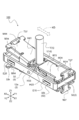
- FIG. 5 is a diagram for explaining the operating device 100 according to the first embodiment of the present invention, and is a perspective view of the main part of the operating device 100.
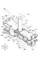
- 6 is a perspective view in which the frame body 32 shown in FIG. 5 is omitted.
- FIG. 7A is a front view seen from the Y2 side shown in FIG. 6, and
- FIG. 7B is a side view seen from the X1 side shown in FIG. In FIG. 7, a part of the operation member 1 is omitted.
- FIG. 8A is a perspective view in which the first movable member H13 and the first magnetic body M14 shown in FIG. 6 are omitted, and
- FIG. 8B shows the second movable member H23 shown in FIG. It is the perspective view which omitted the 2nd magnetic body M24. 5 to 8 show a case where the operation member 1 is in the reference position where the tilt operation in the tilt direction KD is not performed in a state where the operation member 1 is positioned at the reference position PP.
- the operating device 100 has an appearance as shown in FIG. 5, and as shown in FIGS. 6 and 7, an operating member 1 that can be tilted in response to an operator's operation, A support 2 that supports the member 1 with a tilting shaft 12e so that the tilting operation is possible, a first movable member H13 that tilts in the tilting direction KD (X direction shown in FIG.
- first movable member H13, the first magnetic body M14, the second movable member H23, the second magnetic body M24, and the first permanent magnet E15 are arranged in one direction in which the operation member 1 tilts as shown in FIG. It is provided on the side (X1 direction side shown in FIG. 7A).
- the third movable member H33 and the third magnetic body M34, the fourth movable member H43 and the fourth magnetic body M44, and the second permanent magnet E25 are in the other direction in which the operation member 1 tilts with the tilt shaft 12e interposed therebetween. It is provided on the side (X2 direction side shown in FIG. 7B).
- the operation member 1 when the operation member 1 is at the reference position, as shown in FIG. 7, the first magnetic body M14 and the second magnetic body M24 are brought close to each other so that one side of the first permanent magnet E15 (see FIG. 7).
- the first magnetic body M14, the second magnetic body M24, and the first permanent magnet E15 are attracted to each other and the operation member 1 is held at the reference position.
- the third magnetic body M34 and the fourth magnetic body M44 are spaced apart and disposed on one side of the second permanent magnet E25.
- the operating device 100 includes a fifth movable member H53 and a sixth movable member that tilt in the tilt direction KD in conjunction with the operating member 1. H63, a fifth magnetic body M54 provided in the fifth movable member H53, and a sixth magnetic body M64 provided in the sixth movable member H63 (see FIG. 8). Further, as shown in FIG. 7B, the operating device 100 includes a seventh movable member H73 and an eighth movable member H83 that are tilted in the tilt direction KD in conjunction with the operating member 1, and a seventh movable member H73. The seventh magnetic body M74 provided and the eighth magnetic body M84 provided in the eighth movable member H83 are provided.
- the fifth movable member H53 and the fifth magnetic body M54, and the sixth movable member H63 and the sixth magnetic body M64 are arranged in one direction (see FIG. 7A X1 direction side). Further, as shown in FIG. 7, the seventh movable member H73 and the seventh magnetic body M74, and the eighth movable member H83 and the eighth magnetic body M84 are on the other direction side where the operation member 1 is tilted (FIG. 7B). X2 direction side).
- the fifth magnetic body M54 and the sixth magnetic body M64 are brought close to each other and the other side of the first permanent magnet E15 (the lower Z2 direction side shown in FIG. 7).
- the fifth magnetic body M54, the sixth magnetic body M64, and the first permanent magnet E15 are attracted to each other.
- the seventh magnetic body M74 and the eighth magnetic body M84 are spaced apart and disposed on the other side of the second permanent magnet E25.
- FIG. 9 is a diagram for explaining the operation member 1
- FIG. 9A is a perspective view of the operation member 1
- FIG. 9B is an operation when FIG. 9A is viewed from the Y2 side
- 3 is a front view of the member 1.
- FIG. FIG. 10 is a diagram for explaining the operation member 1
- FIG. 10 (a) is a perspective view of the operation member 1 shown in FIG. 9 (a) when viewed from the reverse side
- FIG. 10 (b) It is the rear view of the operation member 1 which looked at Fig.10 (a) from the Y1 side.
- the operation member 1 is manufactured by injection molding a synthetic resin material such as polybutylene terephthalate (PBT), and extends in the vertical direction (Z direction shown in FIG. 5) as shown in FIGS.
- PBT polybutylene terephthalate
- a columnar operation shaft 1j a base portion 1d that is provided on the other end side of the operation shaft 1j and extends in a plane through which the axis of the operation shaft 1j passes, and a hanging portion 1u that extends downward from the base portion 1d.
- the synthetic resin material was used as the operation member 1, it is not restricted to this, For example, you may use metal materials, such as zinc (Zn).
- the operating shaft 1j of the operating member 1 is formed in a columnar shape as shown in FIGS. 9A and 10A, and is formed integrally with the base portion 1d. Further, as shown in FIG. 2, the operation shaft 1j is engaged with the shift knob 50N with the upper portion (the portion exposed from the upper surface of the cover K5) covered with the shift knob 50N of the vehicle shift device 500. Note that the engagement structure between the operation shaft 1j and the shift knob 50N can be applied to a generally widely used engagement structure, and thus detailed description thereof is omitted.
- the base portion 1d of the operation member 1 is provided on the other end side (lower end side) of the operation shaft 1j, and is extended and formed in a direction perpendicular to the axis center of the operation shaft 1j.
- the central portion of the base portion 1d has a direction (FIGS. 9A and 10A) orthogonal to the extending direction of the base portion 1d (the X direction shown in FIGS. 9B and 10B).
- a through-hole 1h penetrating in the Y direction) is provided.
- a tilting shaft 12e of the support 2 that enables the operation member 1 to tilt is inserted into and fitted into the through hole 1h.
- the base member 1d is also configured to rotate in conjunction with the tilting operation of the operation member 1 in the tilting direction KD (X direction shown in FIGS. 9 and 10).
- the base portion 1d when the operating device 100 is assembled, one direction side of the base portion 1d (the X1 direction side shown in FIGS. 9B and 10B) is not shown in detail.
- the first movable member H13 (second movable member H23) is disposed between the fifth movable member H53 (sixth movable member H63).
- FIGS. 9A and 10 when the base portion 1d is rotated about the tilting shaft 12e as shown in FIGS. 9A and 10, the base portion 1d is brought into contact with the first movable member H13. It has a possible first pressing part 11p and a second pressing part 21p that can come into contact with the second movable member H23.
- the first pressing portion 11p and the second pressing portion 21p are respectively provided on one side (the Z1 direction side shown in FIGS. 9B and 10B) of the base portion 1d.
- the first movable member H13 and the first pressing portion 11p are arranged to face each other so that the distance between them is smaller than the distance between the second movable member H23 and the second pressing portion 21p. .
- the fifth movable member H53 is provided on one side of the base portion 1d.
- the fifth pressing part 51p and the sixth pressing part 61p are respectively provided on the other side (Z2 direction side shown in FIG.
- the fifth movable member H53 and the fifth pressing portion 51p are arranged to face each other such that the distance between the sixth movable member H63 and the sixth pressing portion 61p is smaller than the distance between the sixth movable member H63 and the sixth pressing portion 61p.
- the other direction side (X2 direction side shown in FIGS. 9B and 10B) of the base portion 1d is not shown in detail. It is disposed between the third movable member H33 (seventh movable member H73) and the fourth movable member H43 (eighth movable member H83). Then, on the other side of the base portion 1d, as shown in FIG. 10, a first restricting portion 31k that is in contact with the third movable member H33 and a second restricting portion that is in contact with the fourth movable member H43. 41k.
- the first restricting portion 31k and the second restricting portion 41k are respectively provided on one side (Z1 direction side shown in FIG.
- the third movable member H33 and the fourth movable member H43 are movable so that the distance between the third magnetic body M34 and the second permanent magnet E25 is smaller than the distance between the fourth magnetic body M44 and the second permanent magnet E25. It is regulated.
- the 7th control part 71k contact
- the seventh restricting portion 71k and the eighth restricting portion 81k are respectively provided on the other side (the Z2 direction side shown in FIGS. 9B and 10B) of the base portion 1d, and the operation member 1 is provided.
- the seventh movable member H73 and the seventh movable member H73 are arranged so that the distance between the seventh magnetic body M74 and the second permanent magnet E25 is smaller than the distance between the eighth magnetic body M84 and the second permanent magnet E25.
- the movement of the eighth movable member H83 is restricted.
- FIG. 11A is an upper perspective view of the frame body 32 of the support 2
- FIG. 11B is a lower perspective view of the frame body 32 of the support 2.
- the support body 2 includes a tilt shaft 12e that enables the operation member 1 to tilt in the tilt direction KD, and a frame body 32 that supports the tilt shaft 12e so as to be rotatable. It is configured.
- the tilting shaft 12e of the support 2 is made of a nonmagnetic material such as zinc (Zn) and is formed in a cylindrical shape.
- the tilting shaft 12e is inserted into the through hole 1h of the base portion 1d of the operating member 1 and fitted with the operating member 1, and the frame body of the support body 2 is used.
- the nonmagnetic material may be another metal material such as aluminum or copper alloy, or a nonmagnetic synthetic resin material.
- the tilting shaft 12e has the first movable member H13, the second movable member H23, the third movable member H33, the fourth movable member H43, the fourth movable member H43, as shown in FIG.
- the fifth movable member H53, the sixth movable member H63, the seventh movable member H73, and the eighth movable member H83 are movably engaged.
- the base portion 1d and each movable member first movable member H13, second movable member H23, third movable member H33, fourth movable member H43, fifth movable member H53, sixth movable member H63, seventh movable member.
- the member H73 and the eighth movable member H83) rotate (tilt operation) about the tilting shaft 12e of the same support 2 as the axis center.
- the frame body 32 of the support body 2 is manufactured by injection molding a synthetic resin material such as polybutylene terephthalate (PBT), and has an opening whose upper and lower surfaces are open as shown in FIG. And it is formed in a rectangular frame shape.
- PBT polybutylene terephthalate
- the frame body 32 is fixed to the inner side wall of the case K2, and the base portion 1d of the operation member 1 and the second body member 2 are accommodated in the housing portion of the frame body 32.
- the movable member H23 and the second magnetic body M24, the sixth movable member H63 and the sixth magnetic body M64, the first permanent magnet E15, and the second permanent magnet E25 are accommodated.
- holes 32 h are formed in the long side walls of the frame body 32 that face each other in the short direction (Y direction shown in FIG. 11).
- the tilting shaft 12e is inserted through 32h (see FIG. 5), and the tilting shaft 12e is rotatably supported by the frame body 32.
- the operation shaft 1j of the operation member 1 can be rotated in the tilt direction KD with the tilt shaft 12e as the axis center (rotation center), and the base portion 1d of the operation member 1 is also centered on the tilt shaft 12e.
- two frames 32 are formed in the frame body 32 so as to connect between the long side walls opposed to the rectangular cylindrical storage portion 32s.
- An opening hole 32k penetrating the long side wall is formed in the long side wall facing the storage space of the storage portion 32s, and a storage space is formed including the opening hole 32k.
- the first magnetic body M14, the second magnetic body M24, the third magnetic body M34, the fourth magnetic body M44, the fifth magnetic body M54, the sixth magnetic body M64, and the seventh magnetic body are used as the magnetic bodies. It has a body M74 and an eighth magnetic body M84.
- the first movable member H13 and the first magnetic body M14, the fifth movable member H53 and the fifth magnetic body M54, and the second movable body are disposed on one side of the base portion 1d.
- Each of the member H23 and the second magnetic body M24, and the sixth movable member H63 and the sixth magnetic body M64 is made of a soft magnetic body such as iron, and is integrally formed by cutting, bending, or the like. ing.
- the third movable member H33 and the third magnetic body M34, and the seventh movable member H73 and the seventh magnetic body M74 are respectively disposed on the other direction side of the base portion 1d. It is made of a soft magnetic material such as iron and is integrally formed by cutting and bending.
- the fourth movable member H43 and the fourth magnetic body M44 and the eighth movable member H83 and the eighth magnetic body M84 are made of a soft magnetic body such as iron, and are integrally formed by cutting or bending.
- the fourth movable member H43 and the eighth movable member H83 are connected by the connecting portion HR3.
- the connection portion HR3 is preferably used in order to reduce the number of engagements of the movable member with the tilt shaft 12e.
- the present invention is not limited to this.
- the number of parts of the operating device 100 can be reduced, and the thickness of this portion can be reduced.
- the movable member and the magnetic body are preferably formed integrally.
- the present invention is not limited to this and may be formed separately.
- the movable member of the operating device 100 includes a first movable member H13 disposed on one side of the base portion 1d so as to face the first pressing portion 11p of the base portion 1d of the operating member 1, and the base portion 1d.
- the second movable member H23 disposed opposite to the second pressing portion 21p
- the fifth movable member H53 disposed opposite to the fifth pressing portion 51p of the base portion 1d
- the second movable member H53 disposed opposite to the fifth pressing portion 51p of the base portion 1d.
- a sixth movable member H63 disposed to face the six pressing portion 61p.
- the four movable members are tilted in conjunction with the tilting operation of the base portion 1d accompanying the tilting operation of the operation member 1.
- one end sides of the fifth movable member H53 and the sixth movable member H63 are loosely fitted to the tilt shaft 12e so that each of them is centered on the tilt shaft 12e. It is designed to rotate independently.
- the operation member 1 is tilted in one direction of the tilt direction KD (X1 direction shown in FIG. 7A)
- the fifth pressing portion 51p of the base portion 1d that tilts in one direction
- the sixth pressing portion 61p of the base portion 1d see FIG. 10).
- the sixth movable member H63 facing the sixth pressing portion 61p is configured to be pressed.
- the movable member of the operating device 100 includes a third movable member H33 that is in contact with the first restricting portion 31k of the base portion 1d of the operating member 1 and a second portion of the base portion 1d on the other direction side of the base portion 1d.
- the fourth movable member H43 in contact with the restricting portion 41k, the seventh movable member H73 in contact with the seventh restricting portion 71k of the base portion 1d, and the eighth restricting portion 81k of the base portion 1d.
- an eighth movable member H83 The four movable members are tilted in conjunction with the tilting operation of the base portion 1d accompanying the tilting operation of the operation member 1.
- the third movable member H33 and the fourth movable member H43 are loosely fitted to the tilt shaft 12e so as to rotate independently about the tilt shaft 12e.
- the operation member 1 is tilted in the other direction of the tilt direction KD (X2 direction shown in FIG. 7A)
- the first restricting portion 31k The third movable member H33 that has been in contact with the first restricting portion 31k is tilted in the other direction along with the tilting operation of (see FIG. 10) and the tilting operation of the second restricting portion 41k (see FIG. 10).
- the fourth movable member H43 that has been in contact with the second restricting portion 41k is configured to tilt in the other direction.
- one end sides of the seventh movable member H73 and the eighth movable member H83 are loosely fitted to the tilt shaft 12e so that each of them is centered on the tilt shaft 12e. It is designed to rotate independently.
- the seventh restricting portion 71k In accordance with the tilting operation of FIG. 10
- the seventh movable member H73 that has been in contact with the seventh regulating portion 71k tilts in one direction
- the eighth regulating portion 81k tilts.
- the eighth movable member H83 that has been in contact with the eighth restricting portion 81k is configured to tilt in one direction.
- the magnetic body of the operating device 100 includes a first magnetic body M14 provided in (integrated with) the first movable member H13 on one side of the base portion 1d (see FIG. 6), and a second body.
- a sixth magnetic body M64 provided in (integrated with) the sixth movable member H63 (see FIG. 7B), on the other direction side of the base portion 1d, As shown in FIG.
- the first magnetic body M14 is arranged on one side of the first permanent magnet E15 (Z1 direction side shown in FIG. 7).
- the fifth magnetic body M54 is disposed on the other side (Z2 direction side shown in FIG. 7) of the first permanent magnet E15.
- the second magnetic body M24 is disposed between the first magnetic body M14 and the first permanent magnet E15
- the sixth magnetic body M64 is disposed between the fifth magnetic body M54 and the first permanent magnet E15. It is arranged.
- the operation member 1 when the operation member 1 is at the reference position, as shown in FIG. 7, the first magnetic body M14 and the second magnetic body M24 are brought close to each other so that one side of the first permanent magnet E15 (see FIG. 7). The first magnetic body M14, the second magnetic body M24, and the first permanent magnet E15 are attracted to each other. Further, when the operation member 1 is at the reference position, the fifth magnetic body M54 and the sixth magnetic body M64 are brought close to each other and the other side of the first permanent magnet E15 (the lower Z2 direction side shown in FIG. 7). The fifth magnetic body M54, the sixth magnetic body M64, and the first permanent magnet E15 are attracted to each other. As a result, the operation member 1 is held at the reference position.
- each of the magnetic bodies (the first magnetic body M14, the second magnetic body M24, the fifth magnetic body M54, and the sixth magnetic body M64) has the second magnetic body M24 and the sixth magnetic body.
- a space having a constant interval is provided between M64 and the first permanent magnet E15, between the first magnetic body M14 and the second magnetic body M24, and between the fifth magnetic body M54 and the sixth magnetic body M64. Arranged. In order to maintain this constant interval, the magnetic material and the first permanent magnet E15 or the magnetic materials are not attracted to each other by the attractive force of the first permanent magnet E15.
- a mechanism for restricting the movement of the member is provided.
- the storage portion 32s of the frame 32 is disposed between the second magnetic body M24 and the sixth magnetic body M64, the storage portion 32s.
- the second magnetic body M24 and the sixth magnetic body M64 are stopped from adsorbing to the first permanent magnet E15 on the outer surface of the first permanent magnet.
- the thick part of this accommodating part 32s is a fixed space
- the first pressing portion 11p and the first movable member H13 are brought into contact with each other, and the fifth pressing portion 51p and the fifth movable member H53 are brought into contact with each other. Accordingly, the first magnetic body M14 integrated with the first movable member H13 and the second magnetic body M24 facing each other can be kept at a constant distance, and the first movable body H53 integrated with the fifth movable member H53. A constant interval can be maintained between the fifth magnetic body M54 and the sixth magnetic body M64 facing the fifth magnetic body M54.
- a buffer member (not shown) is provided on the storage portion 32s side or the magnetic body side (first side). 2 magnetic body M24, sixth magnetic body M64). Similarly, a buffer member (not shown) is also provided between the first pressing portion 11p and the first movable member H13 or between the fifth pressing portion 51p and the fifth movable member H53.
- a second extending portion T27 extending upward (Z1 direction shown in FIG. 6) from the end portion of the second magnetic body M24. And is formed integrally.
- a sixth extending portion T67 extending downward (in the Z2 direction shown in FIG. 6) from its end is integrated with the sixth magnetic body M64. Is formed.
- the second extending portion T27 has a shape in which a tip end portion projects toward the first magnetic body M14 so that the first magnetic body M14 can come into contact with the first magnetic body M14 when the first magnetic body M14 moves upward.
- the sixth extending portion T67 has a tip portion on the fifth magnetic body M54 side so that it can come into contact with the fifth magnetic body M54. It has an overhanging shape, and restricts excessive movement of the fifth magnetic body M54 to the lower side.
- the third magnetic body M34 is located on one direction side (Z1 direction side shown in FIG. 7) of the second permanent magnet E25.
- the seventh magnetic body M74 is disposed apart from the other side of the second permanent magnet E25 (Z2 direction side shown in FIG. 7).
- the fourth magnetic body M44 is disposed away from the second permanent magnet E25 from the third magnetic body M34
- the eighth magnetic body M84 is disposed away from the second permanent magnet E25 from the seventh magnetic body M74. It is installed.
- the distance between the third magnetic body M34 and the second permanent magnet E25 is arranged to be smaller than the distance between the fourth magnetic body M44 and the second permanent magnet E25.
- the distance between the seventh magnetic body M74 and the second permanent magnet E25 is smaller than the distance between the eighth magnetic body M84 and the second permanent magnet E25.
- the respective magnetic bodies (the third magnetic body M34, the fourth magnetic body M44, the seventh magnetic body M74, and the eighth magnetic body M84) are composed of the third magnetic body M34 and the seventh magnetic body.
- the magnetic material and the second permanent magnet E25 or the magnetic materials are not attracted to each other by the attractive force of the second permanent magnet E25.
- a mechanism for restricting the movement of the member is provided.
- the first restricting portion 31k of the base portion 1d restricts the movement of the third movable member H33, and the third magnetic body M34 is attracted to the second permanent magnet E25.
- the seventh restricting portion 71k of the base portion 1d restricts the movement of the seventh movable member H73 to stop the seventh magnetic body M74 from adsorbing to the second permanent magnet E25.
- the second restricting portion 41k of the base portion 1d restricts the movement of the fourth movable member H43 to stop the fourth magnetic body M44 from adsorbing to the third magnetic body M34, and the base portion 1d.
- the eighth restricting portion 81k restricts the movement of the eighth movable member H83 to stop the eighth magnetic body M84 from adsorbing to the seventh magnetic body M74.
- the buffer member (not shown) is provided on the movable member side (third movable member H33, fourth movable member H43, seventh movable member H73, Eighth movable member H83) or the restricting portion side of the base portion 1d (first restricting portion 31k, second restricting portion 41k, seventh restricting portion 71k, eighth restricting portion 81k).
- a third extending portion T37 extending upward (from the Z1 direction shown in FIG. 8) from the end thereof is provided in the third magnetic body M34. And is formed integrally.
- a seventh extending portion T77 extending downward (in the Z2 direction shown in FIG. 7) from the end portion is provided as the seventh magnetic body. It is formed integrally with the body M74.
- the third extending portion T37 has a shape in which a tip end portion projects toward the fourth magnetic body M44 so that the fourth magnetic body M44 can come into contact with the fourth magnetic body M44 when the fourth magnetic body M44 moves upward.
- the seventh extending portion T77 has a tip portion on the eighth magnetic body M84 side so that it can come into contact with the eighth magnetic body M84. It has an overhanging shape and restricts excessive movement of the eighth magnetic body M84 to the lower side.
- the first permanent magnet E15 and the second permanent magnet E25 of the operating device 100 use a general samarium cobalt magnet or the like, and are formed in a rectangular plate shape as shown in FIG.
- the first permanent magnet E15 is housed and fixed in the housing space of the housing portion 32s of the frame body 32, and is disposed between the second magnetic body M24 and the sixth magnetic body M64. ing.
- the second magnetic body M24 is positioned between the first permanent magnet E15 and the first magnetic body M14, and the sixth magnetic body M64 is the first permanent magnet. It will be located between E15 and the fifth magnetic body M54.
- the second permanent magnet E25 is housed and fixed in the housing space of the housing portion 32s of the frame body 32, and is disposed between the third magnetic body M34 and the seventh magnetic body M74.
- the third magnetic body M34 is positioned between the second permanent magnet E25 and the fourth magnetic body M44, and the seventh magnetic body M74 is the second permanent magnet. It will be located between E25 and the eighth magnetic body M84.
- FIG. 12 is a schematic diagram for explaining the operation in the tilting direction KD in the operating device 100 according to the first embodiment of the present invention.
- FIG. 12A is a diagram of the state of the reference position, and FIG. ) Is a view in a state of being tilted in the other direction of the tilt direction KD (the X2 direction shown in FIG. 7A), and
- FIG. 12C is a view of the other of the tilt direction KD than in FIG. 12B. It is a figure of the state tilted to direction.
- FIG. 13 is a schematic diagram for explaining the operation in the tilting direction KD in the operating device 100 according to the first embodiment of the present invention, and FIG. 13A is a diagram of a state at the same reference position as FIG. FIG.
- FIG. 13 (b) is a view showing a state in which it is tilted in one direction of the tilt direction KD (X1 direction shown in FIG. 7 (a)), and FIG. 13 (c) is a view from FIG. 13 (b). Furthermore, it is a figure of the state inclined in one direction of the inclination direction KD.
- a part of the operation shaft 1j and the frame body 32 are omitted for easy understanding.
- the base portion 1d of the operation member 1 is kept horizontal with respect to the X direction.
- the four movable members (the first movable member H13, the second movable member H23, the fifth movable member H53, and the sixth movable member H63) provided on one side facing the base portion 1d are also kept horizontal.
- the first permanent magnets E15 are sandwiched therebetween, and are disposed in close proximity to each other.
- the second permanent magnet E25 is disposed on one side and the other side of the second permanent magnet E25.
- the fourth movable member H43 and the eighth movable member H83 are connected by a connecting portion HR3. For this reason, the 4th movable member H43 and the 8th movable member H83 move as one.
- the tilt shaft 12e is moved.
- the operation member 1 is rotated about the rotation center, and the base portion 1d is also rotated about the tilt shaft 12e.
- the 1st press part 11p (refer FIG. 10) of the base
- substrate part 1d presses the 1st movable member H13 which opposes, and the 1st movable member H13 comes to rotate upward.
- the first magnetic body M14 integrated with the first movable member H13 also rotates and tilts in the other direction.
- the first magnetic body M14 and the first permanent magnet E15 fixed to the frame body 32 come apart.
- the restricting portions (first restricting portion 31k, second restricting portion 41k, seventh restricting portion 71k, and eighth restricting portion 81k) of the base portion 1d rotate downward.
- the four movable members (the third movable member H33, the fourth movable member H43, the seventh movable member H73, and the eighth movable member H83) supported in contact with the respective restricting portions also rotate downward. become.
- the four integrated magnetic bodies (the third magnetic body M34, the fourth magnetic body M44, the seventh magnetic body M74, and the eighth magnetic body M84) also rotate. Tilting in the other direction.
- the third magnetic body M34 whose distance from the second permanent magnet E25 is shorter than the fourth magnetic body M44 approaches the second permanent magnet E25.
- the operation member 1 is further moved. Rotation is performed, and the base portion 1d is further rotated. Then, on one side, the second pressing member 21p (see FIG. 10A) of the base portion 1d presses the opposing second movable member H23 so that the second movable member H23 rotates upward. become. As the second movable member H23 tilts, the second magnetic body M24 provided in the second movable member H23 also rotates and tilts in the other direction. In that case, as shown in FIG.12 (c), the 2nd magnetic body M24 and the 1st permanent magnet E15 fixed to the frame 32 will come apart.
- the respective restricting portions of the base portion 1d further rotate downward, and the four movable members supported in contact with the respective restricting portions further rotate downward.
- the four integrated magnetic bodies further rotate and tilt in the other direction.
- the fourth magnetic body M44 whose distance from the second permanent magnet E25 is longer than the third magnetic body M34 also approaches the second permanent magnet E25.
- the operating member 1 is tilted from the reference position (reference position PP) to the other direction in the tilting direction KD and is positioned at a plurality of positions.
- the first magnetic body M14 is first separated from the first permanent magnet E15, and the third magnetic body M34 is held close to the second permanent magnet E25, and then the second magnetic body M24. Is separated from the first permanent magnet E15, and the fourth magnetic body M44 is held close to the second permanent magnet E25.
- the operating device 100 has the same configuration in the tilting operation in one direction of the operating member 1 (the X1 direction shown in FIG. 12A). Therefore, the tilting operation in one direction (X1 direction shown in FIG. 13) of the operation member 1 in the tilting direction KD will be described with reference to FIG.
- the tilt shaft 12e is rotated.
- the operation member 1 is rotated as the center of movement, and the base portion 1d is also rotated around the tilting shaft 12e.
- the fifth pressing member 51p (see FIG. 10) of the base 1d presses the opposing fifth movable member H53, and the fifth movable member H53 rotates downward.
- the fifth magnetic body M54 integrated with the fifth movable member H53 also rotates and tilts in one direction. In that case, as shown in FIG.13 (b), the 5th magnetic body M54 and the 1st permanent magnet E15 fixed to the frame 32 come apart.
- the respective restricting portions of the base portion 1d are rotated upward, and the four movable members supported in contact with the respective restricting portions are also rotated upward. become.
- the four integrated magnetic bodies also rotate and tilt in one direction.
- the seventh magnetic body M74 whose distance from the second permanent magnet E25 is shorter than that of the eighth magnetic body M84 approaches the second permanent magnet E25.
- the weak suction state from the strong suction state between the fifth magnetic body M54 and the first permanent magnet E15 is obtained.
- the seventh magnetic body M74 and the second permanent magnet E25 change to a strong attracting state, thereby giving the operator a feeling of being drawn and a stronger sense of moderation (click feeling). become.
- the shift knob 50N It will remain at the position (the back one-stage position S23).
- the operation member 1 is further moved. Rotation is performed, and the base portion 1d is further rotated. Then, on one side, the sixth pressing member 61p (see FIG. 10A) of the base portion 1d presses the opposing sixth movable member H63 so that the sixth movable member H63 rotates downward. become. As the sixth movable member H63 tilts, the sixth magnetic body M64 provided in the sixth movable member H63 also rotates and tilts in the other direction. At that time, as shown in FIG. 13C, the sixth magnetic body M64 and the first permanent magnet E15 fixed to the frame body 32 come apart.
- the respective restricting portions of the base portion 1d further rotate upward, and the four movable members supported in contact with the respective restricting portions further rotate upward. Will come to do.
- the four integrated magnetic bodies further rotate and tilt in one direction.
- the eighth magnetic body M84 having a distance from the second permanent magnet E25 that is longer than the seventh magnetic body M74 also approaches the second permanent magnet E25.
- the operating member 1 when the operating member 1 is positioned from the first rear position S23 to the second rear position S24 (see FIG. 4B), the strong attracting state between the sixth magnetic body M64 and the first permanent magnet E15 is prevented.
- a feeling of moderation a feeling of clicking
- the eighth magnetic body M84 and the second permanent magnet E25 change to a strong attracting state, thereby giving the operator a feeling of being drawn and a stronger sense of moderation (click feeling). become.
- the operating member 1 is tilted in one direction in the tilting direction KD from the reference position (reference position PP) and is positioned at a plurality of positions.
- the fifth magnetic body M54 is separated from the first permanent magnet E15
- the seventh magnetic body M74 is held close to the second permanent magnet E25
- the sixth magnetic body The M64 is separated from the first permanent magnet E15
- the eighth magnetic body M84 is held close to the second permanent magnet E25.
- the operating device 100 can change the magnetic body (first magnetic body M14, second magnetic body) when switching from the reference position to the next position and from the next position to the next position.
- the body M24, the fifth magnetic body M54, the sixth magnetic body M64) and the first permanent magnet E15 are changed from a strong suction state to a weak suction state, and a sense of moderation can be given to the operator. .
- the magnetic body (first magnetic body M14, second magnetic body M24, fifth magnetic body M54, sixth magnetic body M64) and the first permanent magnet E15 are used in the portion that generates a sense of moderation, Compared to the case where the moderation spring 909 and the moderation body 910 are used, the size can be reduced. Furthermore, since the common first permanent magnet E15 is used for one direction and the other direction of the tilting direction KD, it is not necessary to increase the first permanent magnet E15 even if the direction and position of the tilting operation are increased. The price can be reduced and the size can be reduced as compared with the conventional example.
- the magnetic bodies (the third magnetic body M34, the fourth magnetic body M44, the seventh magnetic body M74, and the eighth magnetic body M84) are moved. Since it is held close to the second permanent magnet E25, even after the operator's operation is finished, the operation member 1 is held at that position at each moved position.
- a magnetic body (third magnetic body M34, fourth magnetic body M44, seventh magnetic body M74, eighth magnetic body M84) and a second permanent magnet E25 are provided. Since it was used, it can be similarly reduced in size.
- the operation device 100 according to the first embodiment of the present invention can tilt the operation member 1 in one direction and the other direction (X1 direction and X2 direction) of the tilt direction KD by the operator from the reference position. It is configured. Accordingly, the operating device 100 according to the first embodiment of the present invention can be suitably applied to the vehicle shift device 500 having the shift arrangement (shift pattern) shown in FIG.
- the vehicular shift apparatus 500 is provided at each position (front 1st position S21, front 2nd position S22, reference position PP, rear 1st position S23, rear 2nd position S24, FIG.
- the operation device 100 can be suitably applied to the vehicular shift device 500 because it has a shift arrangement (shift pattern) in which the operation in the tilt direction KD can be performed (see b)).
- the vehicle shift device 500 can perform a shift operation with a sense of moderation, and, compared to the conventional example, there is no sliding mechanism in a portion that causes a sense of moderation in the tilt direction KD.
- the vehicle shift device 500 is excellent in durability.
- the shift knob 50N does not rattle even when the vehicle is traveling, which is more suitable for the vehicle shift device 500.
- the operating device 100 first tilts the first movable member H13 when the operating member 1 is tilted in one direction in the tilting direction KD from the reference position and is positioned at a plurality of positions.
- the first magnetic body M14 is separated from the first permanent magnet E15
- the third magnetic body M34 is held close to the second permanent magnet E25
- the second movable member H23 is tilted with the tilting operation.
- the second magnetic body M24 is separated from the first permanent magnet E15
- the fourth magnetic body M44 is held close to the second permanent magnet E25.
- the strong magnetic state of the first magnetic body M14 and the first permanent magnet E15 is changed to the weak attractive state, and the third magnetic body M34 and the second magnetic body
- the permanent magnet E25 is in a strong attractive state and is held at the next position.
- the second magnetic body M24 and the first permanent magnet E15 change from a strong attraction state to a weak attraction state, and the fourth magnetic body M44 and the second permanent state.
- the magnet E25 is in a strong attractive state and is held at the next position.
- the distance between the first pressing portion 11p of the base portion 1d and the first movable member H13 is the distance between the second pressing portion 21p of the base portion 1d and the second movable member H23. It was simply configured to be disposed opposite each other so as to be smaller.
- the first pressing member 11p presses the opposing first movable member H13 and is provided in the first movable member H13 (integrally
- the first magnetic body M14 is tilted, the first magnetic body M14 and the first permanent magnet E15 are separated from each other, and the tilting operation is continued in the other direction, the second pressing portion 21p
- the opposing second movable member H23 is pressed, the second magnetic body M24 provided in the second movable member H23 is tilted, and the second magnetic body M24 and the first permanent magnet E15 come apart.
- the first magnetic body M14 and the first permanent magnet E15 can be easily separated from each other, and the second magnetic body M24 and the first permanent magnet E15 can be easily separated from each other. be able to. Therefore, it is possible to easily manufacture the operating device 100 having a moderation feeling.
- the first restricting portion 31k of the base portion 1d is in contact with the third movable member H33 to restrict the movement of the third movable member H33, and the second restricting portion 41k of the base portion 1d is the fourth movable member H43. Since the movement of the fourth movable member H43 is restricted in contact with the control member, when the operation member 1 is tilted in the other direction from the reference position, the restricting portions (the first restricting portion 31k and the first restricting portion 31k) 2 regulating part 41k) is tilted to cause the third movable member H33 and the fourth movable member H43 to tilt, and the third magnetic member M34 and the fourth movable member H43 provided in the third movable member H33 are provided. The formed fourth magnetic body M44 is tilted.
- the distance between the third magnetic body M34 and the second permanent magnet E25 is arranged to be smaller than the distance between the fourth magnetic body M44 and the second permanent magnet E25.
- the third magnetic body M34 and the second permanent magnet E25 are strongly attracted and held at the next position, and then the fourth magnetic body M44 and the second permanent magnet E25 are strong.
- the suction state is reached and it is held at the next position. Accordingly, the third magnetic body M34 and the second permanent magnet E25 can be easily attracted corresponding to each position, and the fourth magnetic body M44 and the second permanent magnet E25 can be easily attracted. Therefore, the operation member 1 can be easily held at each position.
- the vehicular shift device 500 according to the first embodiment of the present invention can suitably apply the operation device 100 capable of operating to each position to the shift arrangement (shift pattern) of the vehicular shift device 500.
- a shift operation with a feeling of moderation can be performed, and compared with the conventional example, since there is no sliding mechanism in a portion that generates a feeling of moderation, the vehicle shift device 500 having excellent durability is provided. Can be provided.
- FIG. 14 is a schematic diagram for explaining a first modification of the operating device 100 according to the first embodiment of the present invention.
- FIG. 14A is a side view of a main part of the operating device C100.
- 14 (b) is a side view in which the third movable member CH33 and the third magnetic body CM34, the fifth movable member CH53 and the fifth magnetic body CM54 shown in FIG. 14 (a) are omitted.
- FIG. 15 is a schematic diagram for explaining a modification example, and FIG. 15A is a side view of Modification Examples 3 and 4 in which the positional relationship between the magnetic body and the first permanent magnet E15 is modified.
- FIG. 15B is a side view of Modifications 5 and 6 in which the shape of the magnetic body is modified.
- the sixth movable member H63 and the eighth movable member H83 are separately formed and separately engaged with the tilt shaft 12e.
- the present invention is not limited to this. 14 (see particularly FIG. 14B), the sixth movable member CH63 and the eighth movable member CH83 may be integrally formed and engaged with the tilt shaft 12e ⁇ Modification 1 ⁇ .
- the second movable member CH23 and the fourth movable member CH43 may be integrally formed and engaged with the tilting shaft 12e ⁇ deformation Example 2 ⁇ .
- the fourth movable member CH43 or the eighth movable member CH83 is moved in conjunction with the movement of the second movable member CH23 or the sixth movable member CH63.
- the movement of the fourth movable member CH43 or the eighth movable member CH83 is restricted depending on whether the second movable member CH23 or the sixth movable member CH63 is movable. That is, when the operator performs a tilting operation in the other direction (X2 direction) of the operation member 1, the second movable member CH23 is rotated upward by being pressed by the second pressing portion 21p of the base portion 1d. In conjunction with this, the fourth movable member CH43 is rotated downward.
- the sixth movable member CH63 is rotated downward by being pressed by the sixth pressing portion 61p of the base portion 1d.
- the eighth movable member CH83 rotates upward. Therefore, the second restricting portion 41k that restricts the movement of the fourth movable member H43 and the eighth restricting portion 81k that restricts the movement of the eighth movable member H83, which are configured in the first embodiment, are operated. There is no need to provide it on one base portion C1d. As a result, the number of movable members to be engaged with the tilting shaft 12e can be reduced, and the width direction (extending direction of the tilting shaft 12e) can be narrowed (reduced in size).
- the first permanent magnet E15, the second magnetic body M24, and the first magnetic body M14 are arranged in this order on one side of the first permanent magnet E15. It is not limited.
- the first magnetic body DM14 and the second magnetic body DM24 may be arranged side by side in a direction along the first permanent magnet E15 ⁇ Modification 3 ⁇ .
- the fifth magnetic body DM54 and the sixth magnetic body DM64 may be arranged side by side in the direction along the first permanent magnet E15 ⁇ Modification 4 ⁇ .
- the first magnetic body M14 and the second magnetic body M24 are rectangular and plate-shaped, but the present invention is not limited to this. Instead, for example, as shown in FIG. 15 (b), both ends of the first magnetic body EM14 and the second magnetic body EM24 are bent so as to face the first permanent magnet E15. May be. As a result, the magnetic flux generated by the first permanent magnet E15 is confined by the first magnetic body EM14 and the second magnetic body EM24, and between the first permanent magnet E15, the first magnetic body EM14, and the second magnetic body EM24. The suction power can be increased. As a result, a stronger sense of moderation can be given to the operator.
- the fifth magnetic body M54 and the sixth magnetic body M64 are rectangular and plate-shaped, but the present invention is not limited to this.
- the both ends of the fifth magnetic body EM54 and the sixth magnetic body EM64 are bent so as to face the first permanent magnet E15. It may be a shape. Thereby, the attractive force between the 1st permanent magnet E15, the 5th magnetic body EM54, and the 6th magnetic body EM64 can be raised, and a stronger sense of moderation can be provided with respect to an operator.
- the seventh restricting portion 71k that restricts the movement is provided on the base portion 1d of the operation member 1, the present invention is not limited to this. For example, even if the fourth magnetic body M44 and the third extension T37 are brought into contact with each other using the third extension T37, the movement of the third magnetic body M34 (third movable member H33) is restricted. Good ⁇ Modification 7 ⁇ .
- the eighth magnetic body M84 and the seventh extending portion T77 are brought into contact with each other to restrict the movement of the seventh magnetic body M74 (seventh movable member H73). ⁇ Modification 8 ⁇ . Moreover, you may combine these.
- the tilt shaft 12e of the support 2 is made of a nonmagnetic material such as zinc (Zn), but is not limited thereto.
- a nonmagnetic material such as zinc (Zn)
- it may be made of a soft magnetic material such as iron.
- the eight movable members H83 are preferably configured to rotate around the same tilting shaft 12e, but the present invention is not limited to this.
- the third movable member H33, the fourth movable member H43, the seventh movable member H73, and the eighth movable member H83 may be configured to rotate around another axis ⁇ Modification 11 ⁇ You may comprise all the movable members so that it may rotate centering on a separate tilt axis ⁇ variation 12 ⁇ .
- the present invention is not limited to the above embodiment, and can be appropriately changed without departing from the gist of the present invention.
Landscapes
- Engineering & Computer Science (AREA)
- Chemical & Material Sciences (AREA)
- Combustion & Propulsion (AREA)
- Transportation (AREA)
- Mechanical Engineering (AREA)
- Physics & Mathematics (AREA)
- General Physics & Mathematics (AREA)
- Automation & Control Theory (AREA)
- Arrangement Or Mounting Of Control Devices For Change-Speed Gearing (AREA)
- Mechanical Control Devices (AREA)
Abstract
節度感を有し耐久性に優れた操作装置及び車両用シフト装置を提供することを目的とする。 操作装置(100)は、操作部材(1)と、傾倒軸(12e)を有する支持体(2)と、傾倒軸(12e)を挟んで、一方向側には、第1可動部材(H13)と第2可動部材(H23)と第1磁性体(M14)と第2磁性体(M24)と第1永久磁石(E15)と、他方向側には、第3可動部材(H33)と第4可動部材(H43)と第3磁性体(M34)と第4磁性体(M44)と第2永久磁石(E25)と、を備え、操作部材(1)が基準位置から他方向側に傾倒されて複数のポジションに位置する際に、先ず、第1磁性体(M14)が第1永久磁石(E15)から離れるとともに第3磁性体(M34)が第2永久磁石(E25)に近づいて保持され、次に、第2磁性体(M24)が第1永久磁石(E15)から離れるとともに第4磁性体(M44)が第2永久磁石(E25)に近づいて保持されることを特徴とし、この操作装置(1 00)を車両用シフト装置に好適に適用した。
Description
本発明は、傾倒して操作を行う操作体に用いられる操作装置に関し、特に、磁性体を用いた操作装置及び該操作装置を用いた車両用シフト装置に関する。
一般的に、傾倒して操作を行う操作体は、テレビ、ビデオ等の各種電子機器のリモコンやゲーム機の入力装置、車両用の操作装置等に多く用いられている。特に、ゲーム機の入力装置や車両用の操作装置等では、操作体を把持して傾倒操作を行うタイプの操作装置が用いられている。そして、車両用の操作装置等では、操作フィーリングを向上させるため、操作体を傾倒して切り換え操作をした際に、節度感を持たせることが要望としてあった。
この節度感を有した操作装置として、特許文献1(従来例)では、図16に示すような自動変速機用シフト操作装置900が提案されている。図16は、従来例の自動変速機用シフト操作装置900において、シフトレバー901がNレンジ(ニュートラルレンジ)にあるときの状態を示す拡大縦断面図である。
図16に示す自動変速機用シフト操作装置900は、ノブ902が固着され揺動するシフトレバー901と、シフトレバー901に固着されるともに揺動するホルダ903と、シフトレバー901の揺動を可能にする第1軸905及び第1軸905と直交する第2軸(図示していない)と、第1軸905及び第2軸を軸支するケース904と、から構成される。
そして、自動変速機用シフト操作装置900は、図16に示すように、第1軸905を揺動軸として、Pレンジ(パーキングレンジ)、Rレンジ(リバースレンジ)、Nレンジ(ニュートラルレンジ)及びDレンジ(ドライブレンジ)の各ポジションに、シフトレバー901が揺動できるようになっている。その際に、ホルダ903の下体部903c内に設けられた節度ばね909及び節度体910と、ケース904の内底に形成された節度溝904aとを用いて、シフトレバー901を各ポジション(Pレンジ,Rレンジ,Nレンジ,Dレンジ)に支持したり、シフトレバー901を自動復帰させたりしている。具体的には、節度溝904aは、図16に示すように、シフトレバー901をPレンジに支持する第1節度溝904bと、Rレンジに支持する第2節度溝904cと、Nレンジに支持する第3節度溝904dと、Dレンジに支持する第4節度溝904eと、が前後方向に形成されて構成されており、節度ばね909に付勢された節度体910がこれら節度溝904aを摺動するようになっている。
このように構成された自動変速機用シフト操作装置900は、各ポジション(Pレンジ,Rレンジ,Nレンジ,Dレンジ)に対応して設けられたそれぞれの節度溝904a(904b、904c、904d、904e)を節度体910が移動する際に、シフトレバー901に対して、節度感が与えられるようになっている。
しかしながら、従来例では、この節度感を出すために、節度体910が節度溝904aを摺動する摺動機構を用いているので、シフトレバー901が繰り返して揺動操作がされると、節度溝904aや節度ばね909の摩耗、節度ばね909のバネ性の劣化、節度ばね909と節度体910とのガタツキ等、摺動機構の耐久性が低下するという課題があった。
本発明は、上述した課題を解決するもので、節度感を有し耐久性に優れた操作装置及び該操作装置を用いた車両用シフト装置を提供することを目的とする。
この課題を解決するために、本発明の操作装置は、操作者の操作を受けて傾倒動作が可能な操作部材と、前記傾倒動作が可能に前記操作部材を傾倒軸で支持する支持体と、を備え、前記操作者による基準位置からの傾倒操作を受けて、前記操作部材が位置する複数のポジションを有した操作装置であって、前記操作部材が傾倒する一方向側には、前記操作部材と連動して前記傾倒動作する第1可動部材及び第2可動部材と、該第1可動部材に備えられた第1磁性体と、該第2可動部材に備えられた第2磁性体と、前記支持体に支持された第1永久磁石と、を有し、前記操作部材が傾倒する他方向側には、前記傾倒軸を挟んで、前記操作部材と連動して前記傾倒動作する第3可動部材及び第4可動部材と、該第3可動部材に備えられた第3磁性体と、該第4可動部材に備えられた第4磁性体と、前記支持体に支持された第2永久磁石と、を有し、前記操作部材が前記基準位置にある場合には、前記第1磁性体及び前記第2磁性体が近づけられて前記第1永久磁石の一方側に配設されているとともに、前記第1磁性体及び前記第2磁性体と前記第1永久磁石とが互いに吸引されて前記操作部材が前記基準位置に保持されており、前記第3磁性体及び前記第4磁性体が離間して前記第2永久磁石の一方側に配設されており、前記操作部材が前記基準位置から前記他方向に前記傾倒操作されて前記複数のポジションに位置する際には、先ず前記第1可動部材の前記傾倒動作に伴って前記第1磁性体が前記第1永久磁石から離れるとともに、前記第3可動部材の前記傾倒動作に伴って前記第3磁性体が前記第2永久磁石に近づいて保持され、次に前記第2可動部材の前記傾倒動作に伴って前記第2磁性体が前記第1永久磁石から離れるとともに、前記第4可動部材の前記傾倒動作に伴って前記第4磁性体が前記第2永久磁石に近づいて保持されることを特徴としている。
これによれば、本発明の操作装置は、先ず基準位置から次のポジションへの切り換えに際し、第1磁性体と第1永久磁石との強い吸引状態から弱い吸引状態へ変化するとともに、第3磁性体と第2永久磁石とが強い吸引状態になり次のポジションで保持される。次に、次のポジションから更に次のポジションへの切り換えに際し、第2磁性体と第1永久磁石との強い吸引状態から弱い吸引状態へ変化するとともに、第4磁性体と第2永久磁石とが強い吸引状態になり更に次のポジションで保持されるようになる。このため、他方向への各ポジションへの切り換えに際し、操作者に対して、節度感を与えることができるとともに、移動した各ポジションでその都度操作部材が保持される。このことにより、従来例と比較して、節度感を生じさせる部分に摺動機構がないため、耐久性が優れている。
また、本発明の操作装置は、前記操作部材には、柱状の操作軸と、該操作軸の軸中心が貫く平面に広がる基体部と、を有し、該基体部が前記傾倒動作に伴って回動し、前記基体部には、前記第1可動部材と当接可能な第1押圧部と、前記第2可動部材と当接可能な第2押圧部と、を有し、前記操作部材が前記基準位置にある場合には、前記第1可動部材と前記第1押圧部との距離が前記第2可動部材と前記第2押圧部との距離よりも小さくなるようにそれぞれ対向配設されていることを特徴としている。
これによれば、操作部材が基準位置から他方向に傾倒操作された際に、第1押圧部が対向する第1可動部材を押圧し、第1可動部材に備えられた第1磁性体が傾倒動作されて、第1磁性体と第1永久磁石とが離反し、更に傾倒操作が他方向に継続された際に、第2押圧部が対向する第2可動部材を押圧し、第2可動部材に備えられた第2磁性体が傾倒動作されて、第2磁性体と第1永久磁石とが離反するようになる。このことにより、各ポジションに対応して、第1磁性体と第1永久磁石とを容易に離反させることができるとともに、第2磁性体と第1永久磁石とを容易に離反させることができる。従って、節度感を有した操作装置を容易に作製することができる。
また、本発明の操作装置は、前記基体部には、前記第3可動部材と当接して前記第3可動部材の可動を規制している第1規制部と、前記第4可動部材と当接して前記第4可動部材の可動を規制している第2規制部と、を有し、前記操作部材が前記基準位置にある場合には、前記第3磁性体と前記第2永久磁石との距離が前記第4磁性体と前記第2永久磁石との距離よりも小さくなるように配設されていることを特徴としている。
これによれば、操作部材が基準位置から他方向に傾倒操作された際に、基体部の規制部(第1規制部及び第2規制部)が傾倒動作されることにより第3可動部材及び第4可動部材が傾倒動作し、第3可動部材に備えられた第3磁性体及び第4可動部材に備えられた第4磁性体が傾倒動作されるようになる。そして、先ず第3磁性体と第2永久磁石とが強い吸引状態になり次のポジションで保持され、次に第4磁性体と第2永久磁石とが強い吸引状態になり更に次のポジションで保持されるようになる。このことにより、各ポジションに対応して、第3磁性体と第2永久磁石とを容易に吸引させることができるとともに、第4磁性体と第2永久磁石とを容易に吸引させることができ、操作部材を各ポジションに容易に保持させることができる。
また、本発明の操作装置は、前記基体部には、前記第3可動部材と当接して前記第3可動部材の可動を規制している規制部を有し、前記第4可動部材が前記第2可動部材と一体に形成されていることを特徴としている。
これによれば、操作部材が基準位置から他方向に傾倒操作された際に、基体部の規制部が傾倒動作されることにより第3可動部材が傾倒動作し、第3可動部材に備えられた第3磁性体が傾倒動作されて、第3磁性体と第2永久磁石とが強い吸引状態になり次のポジションで保持される。更に、傾倒操作が他方向に継続された際に、基体部の第2押圧部が対向する第2可動部材を押圧し、第2可動部材と一体に形成されている第4可動部材が傾倒動作し、第4可動部材に備えられた第4磁性体が傾倒動作されて、第4磁性体と第2永久磁石とが強い吸引状態になり更に次のポジションで保持されるようになる。このことにより、各ポジションに対応して、第3磁性体と第2永久磁石とを容易に吸引させることができるとともに、第4磁性体と第2永久磁石とを容易に吸引させることができ、操作部材を各ポジションに容易に保持させることができる。
また、本発明の車両用シフト装置は、上述のいずれかに記載の操作装置と、前記操作装置からの信号を受けて車両側機器に信号を送信する制御部と、前記操作装置の前記操作部材に係合され前記操作者によって把持されるシフトノブと、前記操作部材が位置する前記複数のポジションを検出する位置検出手段と、を備えたことを特徴としている。
これによれば、各ポジションへの操作が行える操作装置を車両用シフト装置のシフトの配置(シフトパターン)に好適に適用することができる。これにより、節度感を有したシフト操作を行うことができ、しかも従来例と比較して、第1方向に関しては、節度感を生じさせる部分に摺動機構がないため、耐久性が優れている。このことにより、節度感を有し耐久性に優れた車両用シフト装置を提供することができる。
本発明の操作装置は、先ず基準位置から次のポジションへの切り換えに際し、第1磁性体と第1永久磁石との強い吸引状態から弱い吸引状態へ変化するとともに、第3磁性体と第2永久磁石とが強い吸引状態になり次のポジションで保持される。次に、次のポジションから更に次のポジションへの切り換えに際し、第2磁性体と第1永久磁石との強い吸引状態から弱い吸引状態へ変化するとともに、第4磁性体と第2永久磁石とが強い吸引状態になり更に次のポジションで保持されるようになる。このため、他方向への各ポジションへの切り換えに際し、操作者に対して、節度感を与えることができるとともに、移動した各ポジションでその都度操作部材が保持される。このことにより、従来例と比較して、節度感を生じさせる部分に摺動機構がないため、耐久性が優れている。
また、各ポジションへの操作が行える操作装置を車両用シフト装置のシフトの配置(シフトパターン)に好適に適用することができる。これにより、節度感を有したシフト操作を行うことができ、しかも従来例と比較して、第1方向に関しては、節度感を生じさせる部分に摺動機構がないため、耐久性が優れている。このことにより、節度感を有し耐久性に優れた車両用シフト装置を提供することができる。
以下、本発明の実施の形態について図面を参照して説明する。
[第1実施形態]
本発明の第1実施形態では、操作装置100及び車両用シフト装置500について説明する。先ず、操作装置100を用いた車両用シフト装置500について説明を行う。
本発明の第1実施形態では、操作装置100及び車両用シフト装置500について説明する。先ず、操作装置100を用いた車両用シフト装置500について説明を行う。
図1は、本発明の第1実施形態に係わる操作装置100を用いた車両用シフト装置500を説明する斜視図である。図2は、本発明の第1実施形態の係わる操作装置100を用いた車両用シフト装置500を説明する図であって、図2(a)は、図1に示すY2側から見た正面図であり、図2(b)は、図1に示すX1側から見た側面図である。図3は、本発明の第1実施形態に係わる操作装置100を用いた車両用シフト装置500を説明する分解斜視図である。
本発明の第1実施形態の操作装置100を用いた車両用シフト装置500は、図1及び図2に示すような箱状の外観を呈し、図3に示すように、操作者によって把持されるシフトノブ50Nと、操作者によるシフトノブ50Nの傾倒操作を受けて操作方向への操作が行える操作装置100と、操作装置100からの信号を受けて車両側機器に信号を送信する制御部50Cと、操作装置100の操作部材1が位置する複数のポジションを検出する位置検出手段(図示していない)と、を備えて構成されている。
他に、本発明の第1実施形態では、車両用シフト装置500は、図3に示すように、操作装置100を収容するケースK2及びケースK2の上側の開放部分を覆うカバーK5(車両用シフト装置500の外観を形成している)と、操作装置100のケースK2に収容され制御部50Cが搭載された配線基板19と、を有している。そして、この車両用シフト装置500は、車両に搭載され、前後の方向(傾倒方向KD、図2(a)に示すX方向)の傾倒操作が行える、車両のシフト操作のために用いられる。
先ず、車両用シフト装置500のシフトノブ50Nは、図1ないし図3に示すように、操作者によって把持し易いように細長い形状で形成され、図1及び図2に示すように、操作装置100の操作部材1の操作軸1j(図3を参照)を覆うようにして、操作部材1に係合されて配設されている。なお、シフトノブ50Nは、ABS樹脂(ABS、acrylonitrile butadiene styrene copolymer)等の合成樹脂を用いて、射出成形されて作製されている。
次に、車両用シフト装置500の制御部50Cは、集積回路(IC、Integrated Circuit)を用いて構成され、箱状のケースK2に収容された配線基板19(図3を参照)に搭載されている。そして、制御部50Cは、図示していないコネクタを介して車両側機器に接続され、シフトノブ50Nの傾倒操作を受けて操作がされた位置情報信号を車両側機器に送信している。この位置情報信号を受けて、車両側では、シフトパターンに対応した動作を行うとともに、シフトパターンにおけるシフトノブ50Nのポジションをインストルメントパネル等に設けられた表示部に表示するようにしている。
次に、車両用シフト装置500の位置検出手段は、図示はしていないが、抵抗体パターンが形成された基板と抵抗パターンを摺接する摺動子とから構成される、所謂回転型可変抵抗器を用いており、傾倒方向KDの傾倒操作での複数のポジションを検出するための位置検出器を有している。そして、この位置検出器は、箱状のケースK2に収容されている。なお、後述するが、位置検出器が支持体2の傾倒軸12e(後述する図6を参照)に係合されて傾倒軸12eの回転角度を検出している。
また、位置検出手段には、位置検出器からの信号を処理する信号処理部52Sを有しており、図3に示すように、信号処理部52Sが配線基板19に搭載されている。また、信号処理部52Sは、図示しないフレキシブルプリント基板(FPC、Flexible printed circuits)を介して、位置検出器に接続されている。そして、信号処理部52Sは、位置検出器からの信号に基づいて傾倒軸12eの回転角度を算出し、この回転角度から操作部材1の傾倒方向KDへの移動を検出している。
最後に、車両用シフト装置500のケースK2、カバーK5及び配線基板19について説明する。
先ず、車両用シフト装置500のケースK2は、ポリブチレンテレフタレート(PBT、polybutyleneterephtalate)等の合成樹脂材を射出成形して作製されており、上面が開放された開口部を有して、矩形状で箱状に形成されている。
次に、車両用シフト装置500のカバーK5は、ケースK2と同様に、ポリブチレンテレフタレート(PBT)等の合成樹脂材を射出成形して作製されており、図3に示すように、板状に形成されて、ケースK2の上方側の開口部を覆うようにして配設されている。なお、詳細な図示はしていないが、カバーK5は、ケースK2と係合されている。
また、カバーK5には、図3に示すように、その中央部分に円形の貫通穴K5hが形成されており、この貫通穴K5hに操作部材1の操作軸1jが挿通されて、操作軸1jがカバーK5の上面側に露出するようになる。これにより、操作装置100の操作部材1の操作軸1jと車両用シフト装置500のシフトノブ50Nとが、係合できるようになる。
最後に、車両用シフト装置500の配線基板19は、一般的な片面のプリント配線板(PWB、printed wiring board)を用いており、前述したように、制御部50C及び信号処理部52Sが搭載されている(図3を参照)。また、配線基板19には、図示はしていないが、位置検出器と信号処理部52Sとの電気的接続のためのフレキシブルプリント基板(FPC)が接続されているとともに、外部機器との接続のためのコネクタが搭載されている。
ここで、本発明の第1実施形態における、操作装置100を用いた車両用シフト装置500のシフト操作について、図4を用いて具体的に説明する。図4は、本発明の第1実施形態に係わる操作装置100を用いた車両用シフト装置500の操作を具体的に説明する図であって、図4(a)は、車両のシフトの配置(シフトパターン)を示した平面図であり、図4(b)は、シフトノブ50Nのポジション位置を示した平面図である。図4(a)に示すシフトパターンは、前述したインストルメントパネル等に設けられた表示部に表示される。また、図4(b)に示すポジション位置は、シフトノブ50N(操作部材1)が操作されて、操作部材1が移動した位置を模式化したものである。なお、図4(a)に示すシフトパターンは、操作装置100が適用される車両用シフト装置500においての一例を示すものであって、このシフトパターンに限るものではない。
本発明の第1実施形態の車両用シフト装置500は、シフトノブ50Nが変速機に直接接続されている機械制御方式の車両ではなく、電子制御方式の車両に適用される。故に、操作装置100から送信されるシフト位置の情報信号だけで、車両のシフト操作が行われる。このシフト位置は、前述したインストルメントパネル等に設けられた表示部に表示されたシフトパターンに示されている。
例えば、シフトノブ50N(操作部材1)が図4(b)に示す基準ポジションPPに位置し、シフト位置が図4(a)に示すニュートラルモード“N”に位置する場合、シフトノブ50Nを傾倒方向KDのX2方向に傾倒操作して、図4(b)に示す前1段ポジションS21に操作すると、図4(a)に示すリバースモード“R”にシフト位置が移動したと、情報信号が車両側に送信され、車両のシフト操作が行われる。そして、操作者は、操作が完了したためシフトノブ50Nから手を離しても、シフトノブ50Nがその位置(前1段ポジションS21)に留まる。
更に、その後の操作で、前1段ポジションS21に位置するシフトノブ50Nを傾倒方向KDのX2方向に傾倒操作し、図4(b)に前2段ポジションS22に操作すると、リバースモード“R”にあったシフト位置が、図4(a)に示すパーキングモード“P”に移動する。この操作を受けて、パーキングモード“P”にシフト位置が移動したと、情報信号が車両側に送信され、車両のシフト操作が行われる。そして、操作者は、操作が完了したためシフトノブ50Nから手を離しても、シフトノブ50Nがその位置(前2段ポジションS22)に留まる。
例えば、シフトノブ50N(操作部材1)が図4(b)に示す基準ポジションPPに位置し、シフト位置が図4(a)に示すニュートラルモード“N”に位置する場合、シフトノブ50Nを傾倒方向KDのX1方向に傾倒操作して、図4(b)に示す後1段ポジションS23に操作すると、図4(a)に示すドライブモード“D”にシフト位置が移動したと、情報信号が車両側に送信され、車両のシフト操作が行われる。そして、操作者は、操作が完了したためシフトノブ50Nから手を離しても、シフトノブ50Nがその位置(後1段ポジションS23)に留まる。
更に、その後の操作で、後1段ポジションS23に位置するシフトノブ50Nを傾倒方向KDのX1方向に傾倒操作し、図4(b)に後2段ポジションS24に操作すると、ドライブモード“D”にあったシフト位置が、図4(a)に示すブレーキングモード“B”に移動する。この操作を受けて、ブレーキングモード“B”にシフト位置が移動したと、情報信号が車両側に送信され、車両のシフト操作が行われる。そして、操作者は、操作が完了したためシフトノブ50Nから手を離しても、シフトノブ50Nがその位置(後2段ポジションS24)に留まる。
このようにして、車両用シフト装置500は、パーキングモード“P”、リバースモード“R”、ニュートラルモード“N”、ドライブモード“D”及びブレーキングモード“B”を有するオート操作に対して、基準位置であるオート操作ポジションを操作装置100の操作部材1の基準ポジションPPに割り付けて使用している。この際に、前述したように、ニュートラルモード“N”からリバースモード“R”、パーキングモード“P”に切り換えるため、操作装置100の操作部材1は、図4(b)に示す前1段ポジションS21、前2段ポジションS22とX2方向に2段に傾倒操作できるようになっている。同様にして、ニュートラルモード“N”からドライブモード“D”、ブレークモード“B”に切り換えるため、操作装置100の操作部材1は、図4(b)に示す後1段ポジションS23、後2段ポジションS24とX1方向に2段に傾倒操作できるようになっている。
以上のように、車両用シフト装置500は、傾倒方向KDに傾倒動作が可能な操作装置100を用いて、図4(a)に示すシフトパターンに対応したシフト操作を行うことができる。なお、図1ないし図3でも、説明を分かり易くするため、傾倒操作の傾倒方向KDを図示している。
次に、操作装置100について説明する。
図5は、本発明の第1実施形態の操作装置100を説明する図であって、操作装置100の主要部分の斜視図である。図6は、図5に示す枠体32を省略した斜視図である。図7(a)は、図6に示すY2側から見た正面図であり、図7(b)は、図6に示すX1側から見た側面図である。図7では、操作部材1の一部を省略している。図8(a)は、図6に示す第1可動部材H13及び第1磁性体M14を省略した斜視図であり、図8(b)は、図8(a)に示す第2可動部材H23及び第2磁性体M24を省略した斜視図である。なお、図5ないし図8は、操作部材1が、基準ポジションPPに位置する状態で、傾倒方向KDの傾倒操作がされない基準位置にある場合を示している。
本発明の第1実施形態の操作装置100は、図5に示すような外観を呈し、図6及び図7に示すように、操作者の操作を受けて傾倒動作可能な操作部材1と、操作部材1を傾倒動作が可能に傾倒軸12eで支持する支持体2と、操作部材1と連動して傾倒方向KD(図7(a)に示すX方向)へ傾倒動作する第1可動部材H13及び第2可動部材H23と、第1可動部材H13に備えられた第1磁性体M14と、第2可動部材H23に備えられた第2磁性体M24と、支持体2に支持された第1永久磁石E15と、操作部材1と連動して傾倒方向KDへ傾倒動作する第3可動部材H33及び第4可動部材H43と、第3可動部材H33に備えられた第3磁性体M34と、第4可動部材H43に備えられた第4磁性体M44と、支持体2に支持された第2永久磁石E25と、を備えて構成されている。
また、この第1可動部材H13及び第1磁性体M14、第2可動部材H23及び第2磁性体M24、並びに第1永久磁石E15は、図7に示すように、操作部材1が傾倒する一方向側(図7(a)に示すX1方向側)に設けられている。また、この第3可動部材H33及び第3磁性体M34、第4可動部材H43及び第4磁性体M44、並びに第2永久磁石E25は、傾倒軸12eを挟んで、操作部材1が傾倒する他方向側(図7(b)に示すX2方向側)に設けられている。
そして、操作部材1が基準位置にある場合には、図7に示すように、第1磁性体M14と第2磁性体M24とが互いに近づけられて第1永久磁石E15の一方側(図7に示す上方のZ1方向側)に配設されているとともに、第1磁性体M14及び第2磁性体M24と第1永久磁石E15とが互いに吸引されて操作部材1が基準位置に保持されている。一方、第3磁性体M34及び第4磁性体M44が離間して第2永久磁石E25の一方側に配設されている。
更に、本発明の第1実施形態では、操作装置100は、図7(b)に示すように、操作部材1に連動して傾倒方向KDへ傾倒動作する第5可動部材H53及び第6可動部材H63と、第5可動部材H53に備えられた第5磁性体M54と、第6可動部材H63に備えられた第6磁性体M64と、を備えている(図8を参照)。また、操作装置100は、図7(b)に示すように、操作部材1と連動して傾倒方向KDへ傾倒動作する第7可動部材H73及び第8可動部材H83と、第7可動部材H73に備えられた第7磁性体M74と、第8可動部材H83に備えられた第8磁性体M84と、を備えている。
また、この第5可動部材H53及び第5磁性体M54、並びに第6可動部材H63及び第6磁性体M64は、図7に示すように、操作部材1が傾倒する一方向側(図7(a)に示すX1方向側)に設けられている。また、この第7可動部材H73及び第7磁性体M74、並びに第8可動部材H83及び第8磁性体M84は、図7に示すように、操作部材1が傾倒する他方向側(図7(b)に示すX2方向側)に設けられている。
そして、操作部材1が基準位置にある場合には、第5磁性体M54と第6磁性体M64とが互いに近づけられて第1永久磁石E15の他方側(図7に示す下方のZ2方向側)に配置されているとともに、第5磁性体M54と第6磁性体M64と第1永久磁石E15が互いに吸引されている。一方、第7磁性体M74及び第8磁性体M84が離間して第2永久磁石E25の他方側に配設されている。
次に、上述した構成要素について詳細に説明する。
先ず、操作装置100の操作部材1について説明する。図9は、操作部材1を説明する図であって、図9(a)は、操作部材1の斜視図であり、図9(b)は、図9(a)をY2側から見た操作部材1の正面図である。図10は、操作部材1を説明する図であって、図10(a)は、図9(a)に示す操作部材1を逆側から見た斜視図であり、図10(b)は、図10(a)をY1側から見た操作部材1の背面図である。
操作部材1は、ポリブチレンテレフタレート(PBT)等の合成樹脂材を射出成形して作製されており、図9及び図10に示すように、垂直方向(図5に示すZ方向)に延在された柱状の操作軸1jと、操作軸1jの他端側に設けられ操作軸1jの軸中心が貫く平面に広がる基体部1dと、基体部1dから下方に延設された下垂部1uと、を有して構成されている。なお、操作部材1として合成樹脂材を用いたが、これに限るものではなく、例えば、亜鉛(Zn)等の金属材を用いても良い。
操作部材1の操作軸1jは、図9(a)及び図10(a)に示すように、円柱形状で形成され、基体部1dと一体に形成されている。また、操作軸1jは、図2に示すように、上方部分(カバーK5の上面から露出する部分)が車両用シフト装置500のシフトノブ50Nに覆われて、シフトノブ50Nと係合されている。なお、操作軸1jとシフトノブ50Nとの係合構造については、一般的に広く用いられる係合構造を適用できるので、詳細な説明は省略する。
操作部材1の基体部1dは、図9及び図10に示すように、操作軸1jの他端側(下端側)に設けられ、操作軸1jの軸中心と直交する方向に延設されて形成されている。また、基体部1dの中央部分には、基体部1dの延在方向(図9(b)及び図10(b)に示すX方向)と直交する方向(図9(a)及び図10(a)に示すY方向)に貫く貫通孔1hが設けられている。この貫通孔1hには、操作部材1の傾倒動作を可能にする支持体2の傾倒軸12eが挿通されて嵌合されている。そして、操作部材1の傾倒方向KD(図9及び図10に示すX方向)への傾倒動作に伴って、基体部1dも連動して回動するように構成されている。
また、操作装置100が組み立てられた際には、基体部1dの一方向側(図9(b)及び図10(b)に示すX1方向側)は、詳細な図示はしていないが、第1可動部材H13(第2可動部材H23)と第5可動部材H53(第6可動部材H63)との間に配設されている。そして、基体部1dの一方向側には、図9(a)及び図10に示すように、基体部1dが傾倒軸12eを軸中心として回動した際に、第1可動部材H13と当接可能な第1押圧部11pと、第2可動部材H23と当接可能な第2押圧部21pと、を有している。この第1押圧部11pと第2押圧部21pとは、基体部1dの一方側(図9(b)及び図10(b)に示すZ1方向側)にそれぞれ設けられており、操作部材1が基準位置にある場合には、第1可動部材H13と第1押圧部11pとの距離が第2可動部材H23と第2押圧部21pとの距離よりも小さくなるようにそれぞれ対向配設されている。
更に、本発明の第1実施形態では、基体部1dの一方向側には、図9に示すように、基体部1dが傾倒軸12eを軸中心として回動した際に、第5可動部材H53と当接可能な第5押圧部51pと、第6可動部材H63と当接可能な第6押圧部61pと、を有している。この第5押圧部51pと第6押圧部61pとは、基体部1dの他方側(図9に示すZ2方向側)にそれぞれ設けられており、操作部材1が基準位置にある場合には、第5可動部材H53と第5押圧部51pとの距離が第6可動部材H63と第6押圧部61pとの距離よりも小さくなるようにそれぞれ対向配設されている。
また、操作装置100が組み立てられた際には、基体部1dの他方向側(図9(b)及び図10(b)に示すX2方向側)は、詳細な図示はしていないが、第3可動部材H33(第7可動部材H73)と第4可動部材H43(第8可動部材H83)との間に配設されている。そして、基体部1dの他方向側には、図10に示すように、第3可動部材H33と当接している第1規制部31kと、第4可動部材H43と当接している第2規制部41kと、を有している。この第1規制部31kと第2規制部41kとは、基体部1dの一方側(図10に示すZ1方向側)にそれぞれ設けられており、操作部材1が基準位置にある場合には、第3磁性体M34と第2永久磁石E25との距離が第4磁性体M44と第2永久磁石E25との距離よりも小さくなるように、第3可動部材H33及び第4可動部材H43の可動をそれぞれ規制している。
更に、本発明の第1実施形態では、基体部1dには、図9(b)及び図10(a)に示すように、第7可動部材H73と当接している第7規制部71kと、第8可動部材H83と当接している第8規制部81kと、を有している。この第7規制部71kと第8規制部81kとは、基体部1dの他方側(図9(b)及び図10(b)に示すZ2方向側)にそれぞれ設けられており、操作部材1が基準位置にある場合には、第7磁性体M74と第2永久磁石E25との距離が第8磁性体M84と第2永久磁石E25との距離よりも小さくなるように、第7可動部材H73及び第8可動部材H83の可動をそれぞれ規制している。
次に、操作装置100の支持体2について説明する。図11(a)は、支持体2の枠体32の上方斜視図であり、図11(b)は、支持体2の枠体32の下方斜視図である。
支持体2は、図5に示すように、操作部材1の傾倒方向KDへの傾倒動作を可能にする傾倒軸12eと、傾倒軸12eの回動を可能に支持する枠体32と、から主に構成されている。
先ず、支持体2の傾倒軸12eは、亜鉛(Zn)等の非磁性体からなり、円柱形状に形成されている。そして、操作装置100が組み立てられた際には、この傾倒軸12eは、操作部材1の基体部1dの貫通孔1hに挿通されて操作部材1と嵌合されるとともに、支持体2の枠体32と回動可能に係合している。なお、非磁性体として、アルミニウムや銅合金等の他の金属材でも良いし、非磁性体の合成樹脂材料でも良い。
また、操作装置100が組み立てられた際には、傾倒軸12eは、図6に示すように、第1可動部材H13、第2可動部材H23、第3可動部材H33、第4可動部材H43、第5可動部材H53、第6可動部材H63、第7可動部材H73及び第8可動部材H83と可動可能に係合している。これにより、基体部1d及び各可動部材(第1可動部材H13、第2可動部材H23、第3可動部材H33、第4可動部材H43、第5可動部材H53、第6可動部材H63、第7可動部材H73及び第8可動部材H83)が同じ支持体2の傾倒軸12eを軸中心として回動する(傾倒動作する)こととなる。このことにより、部品点数を減らすことができるとともに、スペース使用効率が良く小型化を図ることができる。
次に、支持体2の枠体32は、ポリブチレンテレフタレート(PBT)等の合成樹脂材を射出成形して作製されており、図11に示すように、上下面が開放された開口部を有して、矩形状で枠状に形成されている。そして、操作装置100が組み立てられた際には、枠体32は、ケースK2の内側の側壁に固定されるとともに、枠体32の収容部の中に、操作部材1の基体部1d、第2可動部材H23及び第2磁性体M24、第6可動部材H63及び第6磁性体M64、第1永久磁石E15、並びに第2永久磁石E25を収容している。
また、枠体32には、図11に示すように、枠体32の短手方向(図11に示すY方向)に対向する長辺壁にそれぞれ孔部32hが形成されており、この孔部32hに傾倒軸12eが挿通されて(図5を参照)、傾倒軸12eが枠体32に回動可能に支持されている。これにより、この傾倒軸12eを軸中心(回動中心)として、操作部材1の操作軸1jが傾倒方向KDへの回動できるとともに、操作部材1の基体部1dもこの傾倒軸12eを軸中心として回動することができる。一方、この枠体32は、ケースK2の内側の側壁に固定されているので、操作部材1の傾倒方向KDへの傾倒動作と連動しなく、傾倒方向KDへの傾倒動作が行われない部材となっている。
また、枠体32には、図11に示すように、枠内の収容部内に、角形筒状の収納部32sが対向する長辺壁の間を繋ぐように、2つ形成されている。そして、この収納部32sの収納空間と対向する長辺壁には、長辺壁を貫通した開口穴32kが形成されており、この開口穴32kを含めて収納空間を形成している。そして、操作装置100が組み立てられた際には、詳細な図示はしていないが、一方の収納部32sの収納空間に第1永久磁石E15が収納されて固定されるとともに、他方の収納部32sの収納空間に第2永久磁石E25が収納されて固定されるようになっている。
次に、操作装置100の可動部材及び磁性体について説明する。
本発明の第1実施形態に係わる操作装置100では、前述したように、可動部材として、図7(b)に示すように、第1可動部材H13、第2可動部材H23、第3可動部材H33、第4可動部材H43、第5可動部材H53、第6可動部材H63、第7可動部材H73及び第8可動部材H83を有している。また、操作装置100では、磁性体として、第1磁性体M14、第2磁性体M24、第3磁性体M34、第4磁性体M44、第5磁性体M54、第6磁性体M64、第7磁性体M74及び第8磁性体M84を有している。
そして、本発明の第1実施形態では、基体部1dの一方向側には、第1可動部材H13及び第1磁性体M14と、第5可動部材H53及び第5磁性体M54と、第2可動部材H23及び第2磁性体M24と、第6可動部材H63及び第6磁性体M64と、のそれぞれは、鉄等の軟磁性体からなり、切断加工、折り曲げ加工等を施して、一体で形成されている。
更に、本発明の第1実施形態では、基体部1dの他方向側には、第3可動部材H33及び第3磁性体M34と、第7可動部材H73及び第7磁性体M74とのそれぞれは、鉄等の軟磁性体からなり、切断加工、折り曲げ加工等を施して、一体で形成されている。また、第4可動部材H43及び第4磁性体M44と第8可動部材H83及び第8磁性体M84とが、鉄等の軟磁性体からなり、切断加工、折り曲げ加工等を施して、一体で形成されているとともに、図6及び図7(a)に示すように、第4可動部材H43と第8可動部材H83が連結部HR3によって連結されている。なお、本発明の第1実施形態では、可動部材の傾倒軸12eとの係合数を減らすため、好適に連結部HR3を用いた構成としたが、これに限るものではない。
以上のことにより、可動部材及び磁性体において、操作装置100の部品点数を減らすことができるとともに、この部分の薄形化を図ることができる。なお、本発明の第1実施形態では、好適に、可動部材と磁性体とを一体で形成したが、これに限るものではなく、別体で形成しても良い。
先ず、操作装置100の可動部材は、基体部1dの一方向側に、操作部材1の基体部1dの第1押圧部11pと対向して配設された第1可動部材H13と、基体部1dの第2押圧部21pと対向して配設された第2可動部材H23と、基体部1dの第5押圧部51pと対向して配設された第5可動部材H53と、基体部1dの第6押圧部61pと対向して配設された第6可動部材H63と、を有して構成されている。そして、この4つの可動部材は、操作部材1の傾倒操作に伴う基体部1dの傾倒動作と連動して傾倒動作する。
そして、第1可動部材H13及び第2可動部材H23の一端側が傾倒軸12eに回動可能に遊嵌されており、傾倒軸12eを中心にしてそれぞれが独立して回動するようになっている。これにより、操作部材1が傾倒方向KDの他方の向き(図7(a)に示すX2方向)に傾倒操作された際に、他方の向きへ傾倒動作する基体部1dの第1押圧部11p(図10を参照)により、第1押圧部11pと対向する第1可動部材H13が押圧され、更に傾倒操作が他方の向きに継続された際に、基体部1dの第2押圧部21p(図10を参照)により、第2押圧部21pと対向する第2可動部材H23が押圧されるように構成されている。
同様にして、本発明の第1実施形態では、第5可動部材H53及び第6可動部材H63の一端側が傾倒軸12eに回動可能に遊嵌されており、傾倒軸12eを中心にしてそれぞれが独立して回動するようになっている。これにより、操作部材1が傾倒方向KDの一方の向き(図7(a)に示すX1方向)に傾倒操作された際に、一方の向きへ傾倒動作する基体部1dの第5押圧部51p(図10を参照)により、第5押圧部51pと対向する第5可動部材H53が押圧され、更に傾倒操作が一方の向きに継続された際に、基体部1dの第6押圧部61p(図10を参照)により、第6押圧部61pと対向する第6可動部材H63が押圧されるように構成されている。
また、操作装置100の可動部材は、基体部1dの他方向側に、操作部材1の基体部1dの第1規制部31kと当接している第3可動部材H33と、基体部1dの第2規制部41kと当接している第4可動部材H43と、基体部1dの第7規制部71kと当接している第7可動部材H73と、基体部1dの第8規制部81kと当接している第8可動部材H83と、を有して構成されている。そして、この4つの可動部材は、操作部材1の傾倒操作に伴う基体部1dの傾倒動作と連動して傾倒動作する。
そして、第3可動部材H33及び第4可動部材H43の一端側が傾倒軸12eに回動可能に遊嵌されており、傾倒軸12eを中心にしてそれぞれが独立して回動するようになっている。これにより、操作部材1が傾倒方向KDの他方の向き(図7(a)に示すX2方向)に傾倒操作された際に、他方の向きへ傾倒動作する基体部1dの第1規制部31k(図10を参照)の傾倒動作に伴って第1規制部31kに当接していた第3可動部材H33が他方の向きに傾倒動作するとともに、第2規制部41k(図10を参照)の傾倒動作に伴って第2規制部41kに当接していた第4可動部材H43が他方の向きに傾倒動作するように構成されている。
同様にして、本発明の第1実施形態では、第7可動部材H73及び第8可動部材H83の一端側が傾倒軸12eに回動可能に遊嵌されており、傾倒軸12eを中心にしてそれぞれが独立して回動するようになっている。これにより、操作部材1が傾倒方向KDの一方の向き(図7(b)に示すX1方向)に傾倒操作された際に、一方の向きへ傾倒動作する基体部1dの第7規制部71k(図10を参照)の傾倒動作に伴って第7規制部71kに当接していた第7可動部材H73が一方の向きに傾倒動作するとともに、第8規制部81k(図10を参照)の傾倒動作に伴って第8規制部81kに当接していた第8可動部材H83が一方の向きに傾倒動作するように構成されている。
次に、操作装置100の磁性体は、基体部1dの一方向側に、第1可動部材H13に備えられた(一体となった)第1磁性体M14と(図6を参照)、第2可動部材H23に備えられた(一体となった)第2磁性体M24と(図8(a)を参照)、第5可動部材H53に備えられた(一体となった)第5磁性体M54と(図7(b)を参照)、第6可動部材H63に備えられた(一体となった)第6磁性体M64と(図7(b)を参照)、基体部1dの他方向側に、図7(b)に示すように、第3可動部材H33に備えられた(一体となった)第3磁性体M34と、第4可動部材H43に備えられた(一体となった)第4磁性体M44と、第7可動部材H73に備えられた(一体となった)第7磁性体M74と、第8可動部材H83に備えられた(一体となった)第8磁性体M84と、から構成されている。
先ず、基体部1dの一方向側に設けられた磁性体は、図7に示すように、第1磁性体M14が第1永久磁石E15の一方向側(図7に示すZ1方向側)に配設されているとともに、第5磁性体M54が第1永久磁石E15の他方側(図7に示すZ2方向側)に配置されている。更に、第2磁性体M24が第1磁性体M14と第1永久磁石E15との間に配設されているとともに、第6磁性体M64が第5磁性体M54と第1永久磁石E15との間に配設されている。
そして、操作部材1が基準位置にある場合には、図7に示すように、第1磁性体M14と第2磁性体M24とが互いに近づけられて第1永久磁石E15の一方側(図7に示す上方のZ1方向側)に配設されているとともに、第1磁性体M14及び第2磁性体M24と第1永久磁石E15とが互いに吸引されている。更に、操作部材1が基準位置にある場合には、第5磁性体M54と第6磁性体M64とが互いに近づけられて第1永久磁石E15の他方側(図7に示す下方のZ2方向側)に配置されているとともに、第5磁性体M54と第6磁性体M64と第1永久磁石E15が互いに吸引されている。これらにより、操作部材1が基準位置に保持されることとなる。
また、それぞれの磁性体(第1磁性体M14、第2磁性体M24、第5磁性体M54、第6磁性体M64)は、図7に示すように、第2磁性体M24及び第6磁性体M64と第1永久磁石E15との間、第1磁性体M14と第2磁性体M24との間、並びに第5磁性体M54と第6磁性体M64との間に、一定間隔の空間を有して配設されている。この一定間隔を保つためには、第1永久磁石E15の吸引力によって、磁性体と第1永久磁石E15或いは磁性体同士が吸着しないように、詳細な図示はしていなが、磁性体或いは可動部材の可動を規制する機構を有している。
具体的には、本発明の第1実施形態では、第2磁性体M24と第6磁性体M64との間には、枠体32の収納部32sが配設されているので、この収納部32sの外側面で第2磁性体M24及び第6磁性体M64が第1永久磁石E15に吸着するのを止めている。そして、この収納部32sの肉厚部分が第2磁性体M24と第1永久磁石E15との間、第6磁性体M64と第1永久磁石E15との間、の一定間隔となっている。
また、第1押圧部11pと第1可動部材H13とを当接させているとともに、第5押圧部51pと第5可動部材H53とを当接させている。これにより、第1可動部材H13と一体となった第1磁性体M14と対向する第2磁性体M24との間が一定間隔を保つことができるとともに、第5可動部材H53と一体となった第5磁性体M54と対向する第6磁性体M64との間が一定間隔を保つことができる。なお、収納部32sと第2磁性体M24或いは第6磁性体M64とが直接当接する際に生じる当接音を防止するために、図示していない緩衝部材が収納部32s側或いは磁性体側(第2磁性体M24、第6磁性体M64)に設けられている。同様にして、第1押圧部11pと第1可動部材H13との間、または第5押圧部51pと第5可動部材H53との間にも、図示していない緩衝部材が設けられている。
また、図6に示すように、第2磁性体M24の一方向側には、その端部から上方(図6に示すZ1方向)に延出した第2延出部T27が第2磁性体M24と一体となって形成されている。同様にして、第6磁性体M64の一方向側には、その端部から下方(図6に示すZ2方向)に延出した第6延出部T67が第6磁性体M64と一体となって形成されている。
この第2延出部T27は、第1磁性体M14が上方側に移動した際に、第1磁性体M14と当接可能なように、その先端部分が第1磁性体M14側に張り出した形状となっており、第1磁性体M14の上方側への過度の移動を規制している。同様にして、第6延出部T67は、第5磁性体M54が下方側に移動した際に、第5磁性体M54と当接可能なように、その先端部分が第5磁性体M54側に張り出した形状となっており、第5磁性体M54の下方側への過度の移動を規制している。
次に、基体部1dの他方向側に設けられた磁性体は、図7に示すように、第3磁性体M34が第2永久磁石E25の一方向側(図7に示すZ1方向側)に離間して配設されているとともに、第7磁性体M74が第2永久磁石E25の他方側(図7に示すZ2方向側)に離間して配置されている。更に、第4磁性体M44が第3磁性体M34より第2永久磁石E25と離れて配設されているとともに、第8磁性体M84が第7磁性体M74より第2永久磁石E25と離れて配設されている。つまり、操作部材1が基準位置にある場合には、第3磁性体M34と第2永久磁石E25との距離が第4磁性体M44と第2永久磁石E25との距離よりも小さくなるように配設されているとともに、第7磁性体M74と第2永久磁石E25との距離が第8磁性体M84と第2永久磁石E25との距離よりも小さくなるように配設されている。
また、それぞれの磁性体(第3磁性体M34、第4磁性体M44、第7磁性体M74、第8磁性体M84)は、図7に示すように、第3磁性体M34及び第7磁性体M74と第2永久磁石E25との間、第3磁性体M34と第4磁性体M44との間、並びに第7磁性体M74と第8磁性体M84との間に、一定間隔の空間を有して配設されている。この一定間隔を保つためには、第2永久磁石E25の吸引力によって、磁性体と第2永久磁石E25或いは磁性体同士が吸着しないように、詳細な図示はしていなが、磁性体或いは可動部材の可動を規制する機構を有している。
具体的には、本発明の第1実施形態では、基体部1dの第1規制部31kが第3可動部材H33の移動を規制して、第3磁性体M34が第2永久磁石E25に吸着するのを止めているとともに、基体部1dの第7規制部71kが第7可動部材H73の移動を規制して、第7磁性体M74が第2永久磁石E25に吸着するのを止めている。同様にして、基体部1dの第2規制部41kが第4可動部材H43の移動を規制して、第4磁性体M44が第3磁性体M34に吸着するのを止めているとともに、基体部1dの第8規制部81kが第8可動部材H83の移動を規制して、第8磁性体M84が第7磁性体M74に吸着するのを止めている。なお、第3可動部材H33と第1規制部31kと、第4可動部材H43と第2規制部41kと、第7可動部材H73と第7規制部71kと、第8可動部材H83と第8規制部81kと、が、直接当接する際に生じる当接音を防止するために、図示していない緩衝部材が可動部材側(第3可動部材H33、第4可動部材H43、第7可動部材H73、第8可動部材H83)或いは基体部1dの規制部側(第1規制部31k、第2規制部41k、第7規制部71k、第8規制部81k)に設けられている。
また、図8に示すように、第3磁性体M34の他方向側には、その端部から上方(図8に示すZ1方向)に延出した第3延出部T37が第3磁性体M34と一体となって形成されている。同様にして、図7に示すように、第7磁性体M74の他方向側には、その端部から下方(図7に示すZ2方向)に延出した第7延出部T77が第7磁性体M74と一体となって形成されている。
この第3延出部T37は、第4磁性体M44が上方側に移動した際に、第4磁性体M44と当接可能なように、その先端部分が第4磁性体M44側に張り出した形状となっており、第4磁性体M44の上方側への過度の移動を規制している。同様にして、第7延出部T77は、第8磁性体M84が下方側に移動した際に、第8磁性体M84と当接可能なように、その先端部分が第8磁性体M84側に張り出した形状となっており、第8磁性体M84の下方側への過度の移動を規制している。
次に、操作装置100の第1永久磁石E15及び第2永久磁石E25について説明する。第1永久磁石E15及び第2永久磁石E25は、一般的なサマリウムコバルト磁石等を用いており、図8(b)に示すように、矩形で板状の形状で形成されている。
この第1永久磁石E15は、前述したように、枠体32の収納部32sの収納空間に収納されて固定されるとともに、第2磁性体M24と第6磁性体M64との間に配設されている。そして、操作部材1が基準位置にある場合には第2磁性体M24がこの第1永久磁石E15と第1磁性体M14との間に位置するとともに、第6磁性体M64がこの第1永久磁石E15と第5磁性体M54との間に位置することとなる。
また、第2永久磁石E25は、前述したように、枠体32の収納部32sの収納空間に収納されて固定されるとともに、第3磁性体M34と第7磁性体M74との間に配設されている。そして、操作部材1が基準位置にある場合には第3磁性体M34がこの第2永久磁石E25と第4磁性体M44との間に位置するとともに、第7磁性体M74がこの第2永久磁石E25と第8磁性体M84との間に位置することとなる。
ここで、以上で説明した構成要素を用いた傾倒方向KDへの動きについて、図7(a)、図12及び図13に示す模式図を交えながら、その詳細を説明する。なお、ここで説明する傾倒方向KDの動きについては、基準ポジションPPを基準位置として(図4(b)を参照)、操作者の傾倒操作によって行われる動きとして説明する。また、説明を分かり易くするため、紙面裏側に隠れる部分を破線とせずに実線で記述している。
図12は、本発明の第1実施形態の操作装置100における傾倒方向KDの動作を説明する模式図であって、図12(a)は、基準位置の状態の図であり、図12(b)は、傾倒方向KDの他方の向き(図7(a)に示すX2方向)に傾倒した状態の図であり、図12(c)は、図12(b)より更に傾倒方向KDの他方の向きに傾倒した状態の図である。図13は、本発明の第1実施形態の操作装置100における傾倒方向KDの動作を説明する模式図であって、図13(a)は、図12(a)と同じ基準位置の状態の図であり、図13(b)は、傾倒方向KDの一方の向き(図7(a)に示すX1方向)に傾倒した状態の図であり、図13(c)は、図13(b)より更に傾倒方向KDの一方の向きに傾倒した状態の図である。なお、図12及び図13では、説明を分かり易くするため、操作軸1jの一部と枠体32を省略している。
先ず、傾倒方向KDにおける操作部材1の他方の向き(図12に示すX2方向で、他方向側に傾倒する向き)の傾倒動作について、図12を用いて説明する。
先ず、操作部材1が基準ポジションPPの基準位置にある際には、図12(a)に示すように、操作部材1の基体部1dは、X方向に対して水平が保たれており、この基体部1dと対向し一方向側に設けられた4つの可動部材(第1可動部材H13、第2可動部材H23、第5可動部材H53、第6可動部材H63)も水平が保たれている。そして、2つの可動部材にそれぞれ備えられた(一体となった)第1磁性体M14と第5磁性体M54、及び2つの可動部材にそれぞれ備えられた第2磁性体M24と第6磁性体M64が、第1永久磁石E15を間に挟み、近接して対向配設されている。これにより、操作部材1が基準位置(基準ポジションPP)にある場合には、第1永久磁石E15を挟んでそれぞれの磁性体がすべて吸引されているので、操作部材1にガタツキが生じないという効果を奏している。
一方、操作部材1が基準ポジションPPの基準位置にある際には、図12(a)に示すように、他方向側に設けられた4つの可動部材(第3可動部材H33、第4可動部材H43、第7可動部材H73、第8可動部材H83)は、X方向に対して傾斜して、基体部1dのそれぞれの規制部(第1規制部31k、第2規制部41k、第7規制部71k、第8規制部81k)と当接して支持されている。そして、4つの可動部材にそれぞれ備えられた(一体となった)第3磁性体M34及び第4磁性体M44と第7磁性体M74及び第8磁性体M84とが、第2永久磁石E25を間に挟み、離間して、第2永久磁石E25の一方側と他方側にそれぞれ配設されている。なお、図示はしていないが、本発明の第1実施形態では、第4可動部材H43と第8可動部材H83とは、連結部HR3によって連結されている。このため、第4可動部材H43と第8可動部材H83とは一体として可動する。
次に、操作者により操作部材1の図12(a)に示す基準位置(基準ポジションPP)から他方の向き(図12(a)に示すX2方向)に傾倒操作されると、傾倒軸12eを回動中心として操作部材1の回動が行われ、基体部1dも傾倒軸12eを回動中心として回動が行われる。そして、一方向側では、基体部1dの第1押圧部11p(図10を参照)が対向する第1可動部材H13を押圧し、第1可動部材H13が上方側に回動するようになる。そして、第1可動部材H13の傾倒動作に伴って、第1可動部材H13と一体となった第1磁性体M14も回動して他方の向きに傾倒動作する。その際に、図12(b)に示すように、第1磁性体M14と枠体32に固定された第1永久磁石E15とが離反するようになる。
また、同時に、他方向側では、基体部1dのそれぞれの規制部(第1規制部31k、第2規制部41k、第7規制部71k、第8規制部81k)が下方側に回動して、それぞれの規制部と当接して支持されている4つの可動部材(第3可動部材H33、第4可動部材H43、第7可動部材H73、第8可動部材H83)も下方側に回動するようになる。そして、4つの可動部材の傾倒動作に伴って、一体となった4つの磁性体(第3磁性体M34、第4磁性体M44、第7磁性体M74、第8磁性体M84)も回動して他方の向きに傾倒動作する。その際に、図12(b)に示すように、第2永久磁石E25との距離が第4磁性体M44より短い第3磁性体M34が第2永久磁石E25に近づくようになる。
これにより、操作部材1が基準ポジションPPから前1段ポジションS21(図4(b)を参照)に位置する際に、第1磁性体M14と第1永久磁石E15との強い吸引状態から弱い吸引状態へ変化することで、操作者に対して、基準ポジションPPから前1段ポジションS21に移動する際の節度感(クリック感)が得られるようになる。更に、第3磁性体M34と第2永久磁石E25とが強い吸引状態に変化することで、操作者に対して、引き込まれるような感触を与え、より強い節度感(クリック感)が得られるようになる。
また、第3磁性体M34と第2永久磁石E25とが強い吸引状態になり、その位置で保持されるので、操作者が操作が完了してシフトノブ50Nから手を離しても、シフトノブ50Nがその位置(前1段ポジションS21)に留まることとなる。
次に、操作者により操作部材1の図12(b)に示す位置(前1段ポジションS21)から他方の向き(X2方向)への傾倒操作が更に継続されると、操作部材1の更なる回動が行われ、基体部1dも更なる回動が行われる。そして、一方向側では、基体部1dの第2押圧部21p(図10(a)を参照)が対向する第2可動部材H23を押圧し、第2可動部材H23が上方側に回動するようになる。そして、第2可動部材H23の傾倒動作に伴って、第2可動部材H23に備えられた第2磁性体M24も回動して他方の向きに傾倒動作する。その際に、図12(c)に示すように、第2磁性体M24と枠体32に固定された第1永久磁石E15とが離反するようになる。
また、同時に、他方向側では、基体部1dのそれぞれの規制部が下方側に更に回動して、それぞれの規制部と当接して支持されている4つの可動部材も下方側に更に回動するようになる。そして、4つの可動部材の傾倒動作に伴って、一体となった4つの磁性体も更に回動して他方の向きに傾倒動作する。その際に、図12(c)に示すように、第2永久磁石E25との距離が第3磁性体M34より長い第4磁性体M44の方も、第2永久磁石E25に近づくようになる。
これにより、操作部材1が前1段ポジションS21から前2段ポジションS22(図4(b)を参照)に位置する際に、第2磁性体M24と第1永久磁石E15との強い吸引状態から弱い吸引状態へ変化することで、操作者に対して、前1段ポジションS21から前2段ポジションS22に移動する際の節度感(クリック感)が得られるようになる。更に、第4磁性体M44と第2永久磁石E25とが強い吸引状態に変化することで、操作者に対して、引き込まれるような感触を与え、より強い節度感(クリック感)が得られるようになる。
また、第4磁性体M44と第2永久磁石E25とが強い吸引状態になり、その位置で保持されるので、操作者が操作が完了してシフトノブ50Nから手を離しても、シフトノブ50Nがその位置(前2段ポジションS22)に留まることとなる。
以上のように構成された本発明の第1実施形態の操作装置100は、操作部材1が基準位置(基準ポジションPP)から傾倒方向KDの他方の向きに傾倒されて複数のポジションに位置する際には、図12に示すように、先ず第1磁性体M14が第1永久磁石E15から離れるとともに、第3磁性体M34が第2永久磁石E25に近づいて保持され、次に第2磁性体M24が第1永久磁石E15から離れるとともに、第4磁性体M44が第2永久磁石E25に近づいて保持される構成とした。
次に、本発明の第1実施形態の操作装置100では、操作部材1の一方の向き(図12(a)に示すX1方向)の傾倒操作においても、同様な構成を有している。そこで、傾倒方向KDにおける操作部材1の一方の向き(図13に示すX1方向)の傾倒動作についても図13を用いて説明する。
先ず、操作者により操作部材1の図13(a)に示す基準位置(基準ポジションPP)から一方の向き(図13(a)に示すX1方向)に傾倒操作されると、傾倒軸12eを回動中心として操作部材1の回動が行われ、基体部1dも傾倒軸12eを回動中心として回動が行われる。そして、一方向側では、基体部1dの第5押圧部51p(図10を参照)が対向する第5可動部材H53を押圧し、第5可動部材H53が下方側に回動するようになる。そして、第5可動部材H53の傾倒動作に伴って、第5可動部材H53と一体となった第5磁性体M54も回動して一方の向きに傾倒動作する。その際に、図13(b)に示すように、第5磁性体M54と枠体32に固定された第1永久磁石E15とが離反するようになる。
また、同時に、他方向側では、基体部1dのそれぞれの規制部が上方側に回動して、それぞれの規制部と当接して支持されている4つの可動部材も上方側に回動するようになる。そして、4つの可動部材の傾倒動作に伴って、一体となった4つの磁性体も回動して一方の向きに傾倒動作する。その際に、図13(b)に示すように、第2永久磁石E25との距離が第8磁性体M84より短い第7磁性体M74が第2永久磁石E25に近づくようになる。
これにより、操作部材1が基準ポジションPPから後1段ポジションS23(図4(b)を参照)に位置する際に、第5磁性体M54と第1永久磁石E15との強い吸引状態から弱い吸引状態へ変化することで、操作者に対して、基準ポジションPPから後1段ポジションS23に移動する際の節度感(クリック感)が得られるようになる。更に、第7磁性体M74と第2永久磁石E25とが強い吸引状態に変化することで、操作者に対して、引き込まれるような感触を与え、より強い節度感(クリック感)が得られるようになる。
また、第7磁性体M74と第2永久磁石E25とが強い吸引状態になり、その位置で保持されるので、操作者が操作が完了してシフトノブ50Nから手を離しても、シフトノブ50Nがその位置(後1段ポジションS23)に留まることとなる。
次に、操作者により操作部材1の図13(b)に示す位置(後1段ポジションS23)から一方の向き(X1方向)への傾倒操作が更に継続されると、操作部材1の更なる回動が行われ、基体部1dも更なる回動が行われる。そして、一方向側では、基体部1dの第6押圧部61p(図10(a)を参照)が対向する第6可動部材H63を押圧し、第6可動部材H63が下方側に回動するようになる。そして、第6可動部材H63の傾倒動作に伴って、第6可動部材H63に備えられた第6磁性体M64も回動して他方の向きに傾倒動作する。その際に、図13(c)に示すように、第6磁性体M64と枠体32に固定された第1永久磁石E15とが離反するようになる。
また、同時に、他方向側では、基体部1dのそれぞれの規制部が上方側に更に回動して、それぞれの規制部と当接して支持されている4つの可動部材も上方側に更に回動するようになる。そして、4つの可動部材の傾倒動作に伴って、一体となった4つの磁性体も更に回動して一方の向きに傾倒動作する。その際に、図13(c)に示すように、第2永久磁石E25との距離が第7磁性体M74より長い第8磁性体M84の方も、第2永久磁石E25に近づくようになる。
これにより、操作部材1が後1段ポジションS23から後2段ポジションS24(図4(b)を参照)に位置する際に、第6磁性体M64と第1永久磁石E15との強い吸引状態から弱い吸引状態へ変化することで、操作者に対して、後1段ポジションS23から後2段ポジションS24に移動する際の節度感(クリック感)が得られるようになる。更に、第8磁性体M84と第2永久磁石E25とが強い吸引状態に変化することで、操作者に対して、引き込まれるような感触を与え、より強い節度感(クリック感)が得られるようになる。
また、第8磁性体M84と第2永久磁石E25とが強い吸引状態になり、その位置で保持されるので、操作者が操作が完了してシフトノブ50Nから手を離しても、シフトノブ50Nがその位置(前2段ポジションS22)に留まることとなる。
以上のように構成された本発明の第1実施形態の操作装置100は、操作部材1が基準位置(基準ポジションPP)から傾倒方向KDの一方の向きに傾倒されて複数のポジションに位置する際には、図13に示すように、先ず第5磁性体M54が第1永久磁石E15から離れるとともに、第7磁性体M74が第2永久磁石E25に近づいて保持され、、次に第6磁性体M64が第1永久磁石E15から離れるとともに、第8磁性体M84が第2永久磁石E25に近づいて保持される構成とした。
以上のことから、本発明の第1実施形態の操作装置100は、基準位置から次のポジション、次のポジションから更に次のポジションへの切り換えに際し、磁性体(第1磁性体M14、第2磁性体M24、第5磁性体M54、第6磁性体M64)と第1永久磁石E15との強い吸引状態から弱い吸引状態へ変化するようになり、操作者に対して、節度感を与えることができる。このことにより、従来例と比較して、節度感を生じさせる部分に摺動機構がないため、耐久性が優れている。
更に、節度感を生じさせる部分に磁性体(第1磁性体M14、第2磁性体M24、第5磁性体M54、第6磁性体M64)と第1永久磁石E15を用いたので、従来例の節度ばね909及び節度体910を用いた場合と比較して、小型化が可能である。更に、傾倒方向KDの一方の向き及び他方の向きに対して、共通した第1永久磁石E15を用いているので、傾倒動作の向きやポジションを増やしても第1永久磁石E15を増やす必要がなく、低価格化が可能となるとともに、従来例と比較して、小型化が可能である。
また、基準位置から次のポジション、次のポジションから更に次のポジションへ切り換えた後に、磁性体(第3磁性体M34、第4磁性体M44、第7磁性体M74、第8磁性体M84)が第2永久磁石E25に近づいて保持されるので、操作者の操作が終了した後でも、移動した各ポジションでその都度操作部材1がその位置で保持される。
更に、操作部材1を各ポジションに保持させるための機構として、磁性体(第3磁性体M34、第4磁性体M44、第7磁性体M74、第8磁性体M84)と第2永久磁石E25を用いたので、同様にして小型化が可能である。
このように、本発明の第1実施形態の操作装置100は、基準位置から、操作者によりの傾倒方向KDの一方向及び他方向(X1方向及びX2方向)に操作部材1を傾倒操作できるように構成されている。これにより、本発明の第1実施形態の操作装置100は、図4(a)に示すシフトの配置(シフトパターン)を有した車両用シフト装置500に好適に適用することができる。
つまり、本発明の第1実施形態の車両用シフト装置500が各ポジション(前1段ポジションS21、前2段ポジションS22、基準ポジションPP、後1段ポジションS23、後2段ポジションS24、図4(b)を参照)への傾倒方向KDの操作が行えるシフトの配置(シフトパターン)を有しているので、操作装置100は、この車両用シフト装置500に好適に適用することができる。これにより、車両用シフト装置500は、節度感を有したシフト操作を行うことができ、しかも従来例と比較して、傾倒方向KDに関しては、節度感を生じさせる部分に摺動機構がないため、耐久性が優れた車両用シフト装置500となる。
更に、操作装置100の操作部材1が各ポジションにある場合には、第1永久磁石E15と磁性体、或いは、第2永久磁石E25と磁性体が吸引されているので、操作部材1に係合されたシフトノブ50Nが各ポジションにある際に、車両が走行中であってもシフトノブ50Nにガタツキが生じなく、車両用シフト装置500に、より一層好適である。
以上のように構成された本発明の第1実施形態の操作装置100、及びこの操作装置100を用いた車両用シフト装置500における、効果について、以下に纏めて説明する。
本発明の第1実施形態の操作装置100は、操作部材1が基準位置から傾倒方向KDの一方の向きに傾倒動作されて複数のポジションに位置する際には、先ず第1可動部材H13の傾倒動作に伴って第1磁性体M14が第1永久磁石E15から離れるとともに、第3磁性体M34が第2永久磁石E25に近づいて保持され、次に第2可動部材H23の傾倒動作に伴って第2磁性体M24が第1永久磁石E15から離れるとともに、第4磁性体M44が第2永久磁石E25に近づいて保持される構成とした。
これにより、例えば基準位置から次のポジションへの切り換えに際し、先ず、第1磁性体M14と第1永久磁石E15との強い吸引状態から弱い吸引状態へ変化するとともに、第3磁性体M34と第2永久磁石E25とが強い吸引状態になり次のポジションで保持される。次に、次のポジションから更に次のポジションへの切り換えに際し、第2磁性体M24と第1永久磁石E15との強い吸引状態から弱い吸引状態へ変化するとともに、第4磁性体M44と第2永久磁石E25とが強い吸引状態になり更に次のポジションで保持されるようになる。このため、傾倒方向KDの他方の向きの各ポジションへの切り換えに際し、操作者に対して、節度感を与えることができる。このことにより、従来例と比較して、節度感を生じさせる部分に摺動機構がないため、耐久性が優れている。
また、操作部材1が基準位置にある場合に、基体部1dの第1押圧部11pと第1可動部材H13との距離が基体部1dの第2押圧部21pと第2可動部材H23との距離よりも小さくなるようにそれぞれ対向配設されるように簡単に構成した。これにより、操作部材1が基準位置から他方の向きに傾倒操作された際に、第1押圧部11pが対向する第1可動部材H13を押圧し、第1可動部材H13に備えられた(一体となった)第1磁性体M14が傾倒動作されて、第1磁性体M14と第1永久磁石E15とが離反し、更に傾倒操作が他方の向きに継続された際に、第2押圧部21pが対向する第2可動部材H23を押圧し、第2可動部材H23に備えられた第2磁性体M24が傾倒動作されて、第2磁性体M24と第1永久磁石E15とが離反するようになる。このことにより、各ポジションに対応して、第1磁性体M14と第1永久磁石E15とを容易に離反させることができるとともに、第2磁性体M24と第1永久磁石E15とを容易に離反させることができる。従って、節度感を有した操作装置100を容易に作製することができる。
また、基体部1dの第1規制部31kが第3可動部材H33と当接して第3可動部材H33の可動を規制しているとともに、基体部1dの第2規制部41kが第4可動部材H43と当接して第4可動部材H43の可動を規制しているので、操作部材1が基準位置から他方の向きに傾倒操作された際に、基体部1dの規制部(第1規制部31k及び第2規制部41k)が傾倒動作されることにより第3可動部材H33及び第4可動部材H43が傾倒動作し、第3可動部材H33に備えられた第3磁性体M34及び第4可動部材H43に備えられた第4磁性体M44が傾倒動作されるようになる。
そして、操作部材1が基準位置にある場合には、第3磁性体M34と第2永久磁石E25との距離が第4磁性体M44と第2永久磁石E25との距離よりも小さくなるように配設されているので、先ず、第3磁性体M34と第2永久磁石E25とが強い吸引状態になり次のポジションで保持され、次に、第4磁性体M44と第2永久磁石E25とが強い吸引状態になり更に次のポジションで保持されるようになる。このことにより、各ポジションに対応して、第3磁性体M34と第2永久磁石E25とを容易に吸引させることができるとともに、第4磁性体M44と第2永久磁石E25とを容易に吸引させることができ、操作部材1を各ポジションに容易に保持させることができる。
本発明の第1実施形態の車両用シフト装置500は、各ポジションへの操作が行える操作装置100を車両用シフト装置500のシフトの配置(シフトパターン)に好適に適用することができる。これにより、節度感を有したシフト操作を行うことができ、しかも従来例と比較して、節度感を生じさせる部分に摺動機構がないため、耐久性が優れている車両用シフト装置500を提供することができる。
なお、本発明は上記実施形態に限定されるものではなく、例えば次のように変形して実施することができ、これらの実施形態も本発明の技術的範囲に属する。
図14は、本発明の第1実施形態に係わる操作装置100の変形例1を説明する模式図であって、図14(a)は、操作装置C100の主要な部分の側面図であり、図14(b)は、図14(a)に示す第3可動部材CH33及び第3磁性体CM34と第5可動部材CH53及び第5磁性体CM54を省略した側面図である。図15は、変形例を説明する模式図であって、図15(a)は、磁性体及び第1永久磁石E15の位置関係を変形した変形例3及び変形例4の側面図であって、図15(b)は、磁性体の形状を変形した変形例5及び変形例6の側面図である。
<変形例1><変形例2>
上記第1実施形態では、第6可動部材H63と第8可動部材H83とが別々に形成され、傾倒軸12eに別々に係合されている構成であったが、これに限るものではなく、図14(特に図14(b)を参照)に示すように、第6可動部材CH63と第8可動部材CH83とが一体に形成されて、傾倒軸12eに係合されていても良い{変形例1}。同様にして、図14の紙面の裏側で図示はされていないが、第2可動部材CH23と第4可動部材CH43とが一体に形成されて、傾倒軸12eに係合されていても良い{変形例2}。
上記第1実施形態では、第6可動部材H63と第8可動部材H83とが別々に形成され、傾倒軸12eに別々に係合されている構成であったが、これに限るものではなく、図14(特に図14(b)を参照)に示すように、第6可動部材CH63と第8可動部材CH83とが一体に形成されて、傾倒軸12eに係合されていても良い{変形例1}。同様にして、図14の紙面の裏側で図示はされていないが、第2可動部材CH23と第4可動部材CH43とが一体に形成されて、傾倒軸12eに係合されていても良い{変形例2}。
これにより、第2可動部材CH23或いは第6可動部材CH63の可動に連動して、第4可動部材CH43或いは第8可動部材CH83が可動することとなる。言い換えると、第2可動部材CH23或いは第6可動部材CH63の可動の有無により、第4可動部材CH43或いは第8可動部材CH83の可動が規制されることとなる。つまり、操作者により操作部材1の他方の向き(X2方向)への傾倒操作がされると、基体部1dの第2押圧部21pに押圧されて第2可動部材CH23が上方側に回動するのと連動して、第4可動部材CH43が下方側に回動しすることとなる。また、操作者により操作部材1の一方の向き(X1方向)への傾倒操作がされると、基体部1dの第6押圧部61pに押圧されて第6可動部材CH63が下方側に回動するのと連動して、第8可動部材CH83が上方側に回動することとなる。このため、上記第1実施形態で構成した、第4可動部材H43の可動を規制している第2規制部41k及び第8可動部材H83の可動を規制している第8規制部81kを操作部材1の基体部C1dに設ける必要がない。このことにより、傾倒軸12eに係合させる可動部材の箇所を少なくすることができ、幅方向(傾倒軸12eの延在方向)を狭くすることができる(小型化することができる)。
<変形例3><変形例4>
上記第1実施形態では、第1永久磁石E15、第2磁性体M24、第1磁性体M14の順で、第1永久磁石E15の一方側に配設されている構成であったが、これに限るものではない。例えば、図15(a)に示すように、第1磁性体DM14及び第2磁性体DM24が第1永久磁石E15に沿った方向で横並びに配設されていても良い{変形例3}。同様にして、第5磁性体DM54及び第6磁性体DM64が第1永久磁石E15に沿った方向で横並びに配設されていても良い{変形例4}。
上記第1実施形態では、第1永久磁石E15、第2磁性体M24、第1磁性体M14の順で、第1永久磁石E15の一方側に配設されている構成であったが、これに限るものではない。例えば、図15(a)に示すように、第1磁性体DM14及び第2磁性体DM24が第1永久磁石E15に沿った方向で横並びに配設されていても良い{変形例3}。同様にして、第5磁性体DM54及び第6磁性体DM64が第1永久磁石E15に沿った方向で横並びに配設されていても良い{変形例4}。
<変形例5>
上記第1実施形態では、図6及び図8(a)に示すように、第1磁性体M14及び第2磁性体M24が矩形で板状形状をしている構成としたが、これに限るものではなく、例えば、図15(b)に示すように、第1磁性体EM14及び第2磁性体EM24の両端側のそれぞれが第1永久磁石E15と対向するようにして曲げられている形状であっても良い。これにより、第1永久磁石E15が発生する磁束が第1磁性体EM14及び第2磁性体EM24により閉じ込められることとなり、第1永久磁石E15と第1磁性体EM14及び第2磁性体EM24との間の吸引力を高めることができる。このことにより、操作者に対して、より強い節度感を付与することができる。
上記第1実施形態では、図6及び図8(a)に示すように、第1磁性体M14及び第2磁性体M24が矩形で板状形状をしている構成としたが、これに限るものではなく、例えば、図15(b)に示すように、第1磁性体EM14及び第2磁性体EM24の両端側のそれぞれが第1永久磁石E15と対向するようにして曲げられている形状であっても良い。これにより、第1永久磁石E15が発生する磁束が第1磁性体EM14及び第2磁性体EM24により閉じ込められることとなり、第1永久磁石E15と第1磁性体EM14及び第2磁性体EM24との間の吸引力を高めることができる。このことにより、操作者に対して、より強い節度感を付与することができる。
<変形例6>
上記第1実施形態では、図8(b)に示すように、第5磁性体M54及び第6磁性体M64が矩形で板状形状をしている構成としたが、これに限るものではなく、変形例5と同様にして、例えば、図15(b)に示すように、第5磁性体EM54及び第6磁性体EM64の両端側のそれぞれが第1永久磁石E15と対向するようにして曲げられている形状であっても良い。これにより、第1永久磁石E15と第5磁性体EM54及び第6磁性体EM64との間の吸引力を高めることができ、操作者に対して、より強い節度感を付与することができる。
上記第1実施形態では、図8(b)に示すように、第5磁性体M54及び第6磁性体M64が矩形で板状形状をしている構成としたが、これに限るものではなく、変形例5と同様にして、例えば、図15(b)に示すように、第5磁性体EM54及び第6磁性体EM64の両端側のそれぞれが第1永久磁石E15と対向するようにして曲げられている形状であっても良い。これにより、第1永久磁石E15と第5磁性体EM54及び第6磁性体EM64との間の吸引力を高めることができ、操作者に対して、より強い節度感を付与することができる。
<変形例7><変形例8>
上記第1実施形態では、第3可動部材H33と当接して第3可動部材H33の可動を規制している第1規制部31kと、第7可動部材H73と当接して第7可動部材H73の可動を規制している第7規制部71kと、を操作部材1の基体部1dに設けた構成としたが、これに限るものではない。例えば、第3延出部T37を利用して、第4磁性体M44と第3延出部T37とを当接させて第3磁性体M34(第3可動部材H33)の可動を規制しても良い{変形例7}。同様にして、第7延出部T77を利用して、第8磁性体M84と第7延出部T77とを当接させて第7磁性体M74(第7可動部材H73)の可動を規制しても良い{変形例8}。また、これらを組み合わせても良い。
上記第1実施形態では、第3可動部材H33と当接して第3可動部材H33の可動を規制している第1規制部31kと、第7可動部材H73と当接して第7可動部材H73の可動を規制している第7規制部71kと、を操作部材1の基体部1dに設けた構成としたが、これに限るものではない。例えば、第3延出部T37を利用して、第4磁性体M44と第3延出部T37とを当接させて第3磁性体M34(第3可動部材H33)の可動を規制しても良い{変形例7}。同様にして、第7延出部T77を利用して、第8磁性体M84と第7延出部T77とを当接させて第7磁性体M74(第7可動部材H73)の可動を規制しても良い{変形例8}。また、これらを組み合わせても良い。
<変形例9>
上記第1実施形態では、支持体2の傾倒軸12eを亜鉛(Zn)等の非磁性体で作製したが、これに限るものではない。例えば、鉄等の軟磁性体で作製しても良い。
上記第1実施形態では、支持体2の傾倒軸12eを亜鉛(Zn)等の非磁性体で作製したが、これに限るものではない。例えば、鉄等の軟磁性体で作製しても良い。
<変形例10>
上記第1実施形態では、第5可動部材H53、第6可動部材H63、第5磁性体M54、第6磁性体M64、第5押圧部51p及び第6押圧部61pを好適に用いた構成としたが、これに限るものではなく、例えばこれらの構成要素が無い構成でも良い。
上記第1実施形態では、第5可動部材H53、第6可動部材H63、第5磁性体M54、第6磁性体M64、第5押圧部51p及び第6押圧部61pを好適に用いた構成としたが、これに限るものではなく、例えばこれらの構成要素が無い構成でも良い。
<変形例11><変形例12>
上記第1実施形態では、第1可動部材H13、第2可動部材H23、第3可動部材H33、第4可動部材H43、第5可動部材H53、第6可動部材H63、第7可動部材H73及び第8可動部材H83が、同一の傾倒軸12eを軸中心として回動するように好適に構成したが、これに限るものではない。例えば、第3可動部材H33、第4可動部材H43、第7可動部材H73及び第8可動部材H83が別な軸を軸中心として回動するように構成しても良いし{変形例11}、全ての可動部材が別々な傾倒軸を軸中心として回動するように構成しても良い{変形例12}。
上記第1実施形態では、第1可動部材H13、第2可動部材H23、第3可動部材H33、第4可動部材H43、第5可動部材H53、第6可動部材H63、第7可動部材H73及び第8可動部材H83が、同一の傾倒軸12eを軸中心として回動するように好適に構成したが、これに限るものではない。例えば、第3可動部材H33、第4可動部材H43、第7可動部材H73及び第8可動部材H83が別な軸を軸中心として回動するように構成しても良いし{変形例11}、全ての可動部材が別々な傾倒軸を軸中心として回動するように構成しても良い{変形例12}。
本発明は上記実施の形態に限定されず、本発明の要旨を逸脱しない限りにおいて適宜変更することが可能である。
1 操作部材
1d、C1d 基体部
1j 操作軸
11p 第1押圧部
21p 第2押圧部
31k 第1規制部
41k 第2規制部
2 支持体
12e 傾倒軸
H13 第1可動部材
H23、CH23 第2可動部材
H33、CH33 第3可動部材
H43、CH43 第4可動部材
M14、DM14、EM14 第1磁性体
M24、DM24、EM24 第2磁性体
M34、CM34 第3磁性体
M44 第4磁性体
E15 第1永久磁石
E25 第2永久磁石
100、C100 操作装置
KD 傾倒方向
50C 制御部
50N シフトノブ
500 車両用シフト装置
1d、C1d 基体部
1j 操作軸
11p 第1押圧部
21p 第2押圧部
31k 第1規制部
41k 第2規制部
2 支持体
12e 傾倒軸
H13 第1可動部材
H23、CH23 第2可動部材
H33、CH33 第3可動部材
H43、CH43 第4可動部材
M14、DM14、EM14 第1磁性体
M24、DM24、EM24 第2磁性体
M34、CM34 第3磁性体
M44 第4磁性体
E15 第1永久磁石
E25 第2永久磁石
100、C100 操作装置
KD 傾倒方向
50C 制御部
50N シフトノブ
500 車両用シフト装置
Claims (5)
- 操作者の操作を受けて傾倒動作が可能な操作部材と、前記傾倒動作が可能に前記操作部材を傾倒軸で支持する支持体と、を備え、前記操作者による基準位置からの傾倒操作を受けて、前記操作部材が位置する複数のポジションを有した操作装置であって、
前記操作部材が傾倒する一方向側には、前記操作部材と連動して前記傾倒動作する第1可動部材及び第2可動部材と、該第1可動部材に備えられた第1磁性体と、該第2可動部材に備えられた第2磁性体と、前記支持体に支持された第1永久磁石と、を有し、
前記操作部材が傾倒する他方向側には、前記傾倒軸を挟んで、前記操作部材と連動して前記傾倒動作する第3可動部材及び第4可動部材と、該第3可動部材に備えられた第3磁性体と、該第4可動部材に備えられた第4磁性体と、前記支持体に支持された第2永久磁石と、を有し、
前記操作部材が前記基準位置にある場合には、
前記第1磁性体及び前記第2磁性体が近づけられて前記第1永久磁石の一方側に配設されているとともに、前記第1磁性体及び前記第2磁性体と前記第1永久磁石とが互いに吸引されて前記操作部材が前記基準位置に保持されており、
前記第3磁性体及び前記第4磁性体が離間して前記第2永久磁石の一方側に配設されており、
前記操作部材が前記基準位置から前記他方向に前記傾倒操作されて前記複数のポジションに位置する際には、先ず前記第1可動部材の前記傾倒動作に伴って前記第1磁性体が前記第1永久磁石から離れるとともに、前記第3可動部材の前記傾倒動作に伴って前記第3磁性体が前記第2永久磁石に近づいて保持され、次に前記第2可動部材の前記傾倒動作に伴って前記第2磁性体が前記第1永久磁石から離れるとともに、前記第4可動部材の前記傾倒動作に伴って前記第4磁性体が前記第2永久磁石に近づいて保持されることを特徴とする操作装置。 - 前記操作部材には、柱状の操作軸と、該操作軸の軸中心が貫く平面に広がる基体部と、を有し、
該基体部が前記傾倒動作に伴って回動し、
前記基体部には、前記第1可動部材と当接可能な第1押圧部と、前記第2可動部材と当接可能な第2押圧部と、を有し、
前記操作部材が前記基準位置にある場合には、前記第1可動部材と前記第1押圧部との距離が前記第2可動部材と前記第2押圧部との距離よりも小さくなるようにそれぞれ対向配設されていることを特徴とする請求項1に記載の操作装置。 - 前記基体部には、前記第3可動部材と当接して前記第3可動部材の可動を規制している第1規制部と、前記第4可動部材と当接して前記第4可動部材の可動を規制している第2規制部と、を有し、
前記操作部材が前記基準位置にある場合には、前記第3磁性体と前記第2永久磁石との距離が前記第4磁性体と前記第2永久磁石との距離よりも小さくなるように配設されていることを特徴とする請求項2に記載の操作装置。 - 前記基体部には、前記第3可動部材と当接して前記第3可動部材の可動を規制している規制部を有し、
前記第4可動部材が前記第2可動部材と一体に形成されていることを特徴とする請求項2に記載の操作装置。 - 請求項1ないし請求項4のいずれかに記載の操作装置と、
前記操作装置からの信号を受けて車両側機器に信号を送信する制御部と、
前記操作装置の前記操作部材に係合され前記操作者によって把持されるシフトノブと、
前記操作部材が位置する前記複数のポジションを検出する位置検出手段と、を備えたことを特徴とする車両用シフト装置。
Priority Applications (1)
| Application Number | Priority Date | Filing Date | Title |
|---|---|---|---|
| JP2018516353A JP6560822B2 (ja) | 2016-05-12 | 2017-02-24 | 操作装置、該操作装置を用いた車両用シフト装置 |
Applications Claiming Priority (2)
| Application Number | Priority Date | Filing Date | Title |
|---|---|---|---|
| JP2016095696 | 2016-05-12 | ||
| JP2016-095696 | 2016-05-12 |
Publications (1)
| Publication Number | Publication Date |
|---|---|
| WO2017195432A1 true WO2017195432A1 (ja) | 2017-11-16 |
Family
ID=60267014
Family Applications (1)
| Application Number | Title | Priority Date | Filing Date |
|---|---|---|---|
| PCT/JP2017/007131 Ceased WO2017195432A1 (ja) | 2016-05-12 | 2017-02-24 | 操作装置、該操作装置を用いた車両用シフト装置 |
Country Status (2)
| Country | Link |
|---|---|
| JP (1) | JP6560822B2 (ja) |
| WO (1) | WO2017195432A1 (ja) |
Cited By (4)
| Publication number | Priority date | Publication date | Assignee | Title |
|---|---|---|---|---|
| WO2019102718A1 (ja) * | 2017-11-24 | 2019-05-31 | アルプスアルパイン株式会社 | 操作装置 |
| US11334106B2 (en) * | 2018-11-20 | 2022-05-17 | Inventus Engineering Gmbh | Operator control device |
| DE102024107544A1 (de) * | 2024-03-15 | 2025-09-18 | Signata GmbH | Schalteinheit |
| WO2025190441A1 (de) * | 2024-03-15 | 2025-09-18 | Signata GmbH | Schalteinheit |
Citations (3)
| Publication number | Priority date | Publication date | Assignee | Title |
|---|---|---|---|---|
| JP2012071649A (ja) * | 2010-09-28 | 2012-04-12 | Tokai Rika Co Ltd | シフト装置 |
| JP2015143910A (ja) * | 2014-01-31 | 2015-08-06 | アルプス電気株式会社 | 多方向入力操作装置及び該多方向入力操作装置を用いた車両用シフト装置 |
| JP2015149058A (ja) * | 2014-01-07 | 2015-08-20 | アルプス電気株式会社 | 操作装置及び該操作装置を用いた車両用シフト装置 |
-
2017
- 2017-02-24 WO PCT/JP2017/007131 patent/WO2017195432A1/ja not_active Ceased
- 2017-02-24 JP JP2018516353A patent/JP6560822B2/ja active Active
Patent Citations (3)
| Publication number | Priority date | Publication date | Assignee | Title |
|---|---|---|---|---|
| JP2012071649A (ja) * | 2010-09-28 | 2012-04-12 | Tokai Rika Co Ltd | シフト装置 |
| JP2015149058A (ja) * | 2014-01-07 | 2015-08-20 | アルプス電気株式会社 | 操作装置及び該操作装置を用いた車両用シフト装置 |
| JP2015143910A (ja) * | 2014-01-31 | 2015-08-06 | アルプス電気株式会社 | 多方向入力操作装置及び該多方向入力操作装置を用いた車両用シフト装置 |
Cited By (7)
| Publication number | Priority date | Publication date | Assignee | Title |
|---|---|---|---|---|
| WO2019102718A1 (ja) * | 2017-11-24 | 2019-05-31 | アルプスアルパイン株式会社 | 操作装置 |
| CN111373343A (zh) * | 2017-11-24 | 2020-07-03 | 阿尔卑斯阿尔派株式会社 | 操作装置 |
| US10802528B2 (en) | 2017-11-24 | 2020-10-13 | Alps Alpine Co., Ltd. | Operating device |
| CN111373343B (zh) * | 2017-11-24 | 2022-03-22 | 阿尔卑斯阿尔派株式会社 | 操作装置 |
| US11334106B2 (en) * | 2018-11-20 | 2022-05-17 | Inventus Engineering Gmbh | Operator control device |
| DE102024107544A1 (de) * | 2024-03-15 | 2025-09-18 | Signata GmbH | Schalteinheit |
| WO2025190441A1 (de) * | 2024-03-15 | 2025-09-18 | Signata GmbH | Schalteinheit |
Also Published As
| Publication number | Publication date |
|---|---|
| JP6560822B2 (ja) | 2019-08-14 |
| JPWO2017195432A1 (ja) | 2019-01-17 |
Similar Documents
| Publication | Publication Date | Title |
|---|---|---|
| JP6452155B2 (ja) | 多方向操作装置及び該多方向操作装置を用いた車両用シフト装置 | |
| JP6202627B2 (ja) | 操作装置及び該操作装置を用いた車両用シフト装置 | |
| JPWO2017138429A1 (ja) | 操作装置、該操作装置を用いた車両用シフト装置 | |
| JP5930226B2 (ja) | 多方向入力操作装置及び該多方向入力操作装置を用いた車両用シフト装置 | |
| JP6422079B2 (ja) | 操作装置及び該操作装置を用いた車両用シフト装置 | |
| JP6560822B2 (ja) | 操作装置、該操作装置を用いた車両用シフト装置 | |
| JP6440145B2 (ja) | 操作装置、該操作装置を用いた車両用シフト装置 | |
| JP6735356B2 (ja) | 操作装置及びその操作装置を用いた車両用シフト装置 | |
| JP6713058B2 (ja) | 操作装置及びその操作装置を用いた車両用シフト装置 | |
| JP2015122257A (ja) | 多方向操作装置及び該多方向操作装置を用いた車両用シフト装置 | |
| JP5871340B2 (ja) | 多方向入力操作装置及び該多方向入力操作装置を用いた車両用シフト装置 | |
| JP6403137B2 (ja) | 操作装置及び該操作装置を用いた車両用シフト装置 | |
| JP6452154B2 (ja) | 操作装置、該操作装置を用いた車両用シフト装置 | |
| US10802528B2 (en) | Operating device | |
| JP6432984B2 (ja) | 操作装置及び該操作装置を用いた車両用シフト装置 |
Legal Events
| Date | Code | Title | Description |
|---|---|---|---|
| WWE | Wipo information: entry into national phase |
Ref document number: 2018516353 Country of ref document: JP |
|
| NENP | Non-entry into the national phase |
Ref country code: DE |
|
| 121 | Ep: the epo has been informed by wipo that ep was designated in this application |
Ref document number: 17795793 Country of ref document: EP Kind code of ref document: A1 |
|
| 122 | Ep: pct application non-entry in european phase |
Ref document number: 17795793 Country of ref document: EP Kind code of ref document: A1 |