WO2017195421A1 - 抜枠造型ラインにおける重錘載置設備及び重錘載置方法 - Google Patents
抜枠造型ラインにおける重錘載置設備及び重錘載置方法 Download PDFInfo
- Publication number
- WO2017195421A1 WO2017195421A1 PCT/JP2017/004722 JP2017004722W WO2017195421A1 WO 2017195421 A1 WO2017195421 A1 WO 2017195421A1 JP 2017004722 W JP2017004722 W JP 2017004722W WO 2017195421 A1 WO2017195421 A1 WO 2017195421A1
- Authority
- WO
- WIPO (PCT)
- Prior art keywords
- weight
- mold
- lowering
- jacket
- deceleration position
- Prior art date
- Legal status (The legal status is an assumption and is not a legal conclusion. Google has not performed a legal analysis and makes no representation as to the accuracy of the status listed.)
- Ceased
Links
Images





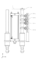

Classifications
-
- B—PERFORMING OPERATIONS; TRANSPORTING
- B22—CASTING; POWDER METALLURGY
- B22C—FOUNDRY MOULDING
- B22C11/00—Moulding machines characterised by the relative arrangement of the parts of same
-
- B—PERFORMING OPERATIONS; TRANSPORTING
- B22—CASTING; POWDER METALLURGY
- B22C—FOUNDRY MOULDING
- B22C21/00—Flasks; Accessories therefor
- B22C21/12—Accessories
-
- B—PERFORMING OPERATIONS; TRANSPORTING
- B22—CASTING; POWDER METALLURGY
- B22C—FOUNDRY MOULDING
- B22C23/00—Tools; Devices not mentioned before for moulding
Definitions
- the present disclosure relates to a weight placement facility and a weight placement method for placing a weight on a mold of a frame forming line.
- a taper-shaped jacket is put on the outer periphery of the casting mold, and the casting is overlaid on the casting mold. A weight is placed. After the melt has solidified, the jacket and weight are removed from the mold and the cast product is removed.
- Patent Document 1 describes a weight jacket transfer device in a frame making line.
- the weight jacket transfer device described in Patent Document 1 removes the weight from the mold on the cooling line and installs the weight on the mold on the pouring line. Then, the jacket is removed from the mold on the cooling line, and the jacket is put on the mold on the pouring line.
- the pouring line and the cooling line described in Patent Document 1 are arranged in parallel, and the weight jacket transfer device is arranged across the pouring line and the cooling line. Therefore, the space required for changing the weight and jacket can be suppressed.
- the descent speed of the weight from when the weight starts to fall until it is placed on the mold is such that the mold does not collapse due to the impact when the weight is placed on the mold. Is set. Since this speed is low, the cycle time from when the weight starts to descend until it is placed on the mold becomes long.
- one form of the present disclosure is a weight placement facility for placing a weight on a mold on a frame forming line, wherein the weight is lowered to be placed on the mold.
- the descending speed includes a first descending speed from the start of descending to reaching the deceleration position, and a second descending speed from the deceleration position to being placed on the mold.
- the second descending speed is lower than the first descending speed.
- the deceleration position determining device determines the deceleration position of the weight descending direction in the weight lifting device.
- the weight is lowered by the weight lifting device to be placed on the mold.
- the descent speed of the weight is a section from the start of the descent until reaching the deceleration position (first section), and a section from the deceleration position to being placed on the mold (second section).
- the descending speed of the weight in the second section (second descending speed) is set to a speed at which the mold does not collapse due to the impact when the weight is placed. That is, the descending speed (first descending speed) of the weight in the first section is set at a speed faster than the second descending speed.
- the weight mounting facility may further include a jacket lifting / lowering device that is disposed upstream of the weight lifting / lowering device and covers a jacket on a side surface of the mold.
- the deceleration position determining device may be disposed in the jacket lifting device. According to this aspect, the deceleration position determination device operates when the jacket lifting device provided upstream of the weight lifting device is operating, and determines the deceleration position of the weight lifting direction in the weight lifting device. can do.
- the deceleration position determination device may include an optical measurement unit that is disposed in the weight lifting device and measures a distance to the upper surface of the mold using light.
- the light measuring means may be arranged so that light emitted from the light measuring means hits the upper surface of the mold perpendicularly.
- the distance from the weight lifting device to the upper surface of the mold is measured by the optical measuring means provided in the weight lifting device.
- the deceleration position is determined by the deceleration position determination device.
- the measurement of the distance to the upper surface of the mold and the determination of the deceleration position of the weight can be performed with one apparatus called an optical measurement unit.
- the deceleration position determination device includes a first detector that can be moved up and down relative to the jacket lifting device, and a first detector that moves up and down together with the jacket lifting device and detects the first detection body.
- the first proximity switch may include a plurality of proximity switches corresponding to different heights of the mold.
- the weight lifting device may include a deceleration position detection device that detects the deceleration position.
- the deceleration position detection device includes: a second detector that moves up and down with the lifting operation of the weight lifting device; and a second proximity switch that is attached to the weight lifting device and detects the second detection body. You may have.
- the second proximity switch may include a plurality of proximity switches corresponding to different mold heights. Since the proximity switch can be easily replaced, it is possible to quickly respond to problems such as damage. Therefore, according to this form, it becomes the weight mounting equipment excellent in maintainability.
- the deceleration position determination device may further include a bar member extending in a height direction of the mold.
- the first detection body may be disposed at an upper end of the bar member, and a lower end of the bar member may be disposed so as to be able to contact a collar portion formed on the jacket.
- the deceleration position can be determined with a simple structure.
- the first detector may have a cylindrical shape extending in the height direction of the mold and having an open lower end. If the shape of the first detection body is a cylindrical shape having an open upper end, foundry sand will enter the first detection body. Moreover, if the shape of the first detection body is a cylindrical shape, the material cost of the first detection body will be expensive. According to this embodiment, the first detection body can keep the foundry sand inside, and can keep the material cost low.
- Another embodiment of the present disclosure is a method of placing a weight on a mold on the above-described frame forming line, and a jacket covering step of lowering the jacket and covering the side surface of the mold with the jacket lifting device
- the weight is lowered at the second lowering speed from the deceleration position until the weight is placed on the mold by the first weight lowering step of lowering at the first lowering speed and the weight lifting device.
- a second double weight lowering step is a second double weight lowering step.
- this weight placement method the deceleration position of the weight is determined by the first detector and the first proximity switch, and the descending speed of the weight decreases at the deceleration position, and the weight is placed on the mold. Is done. For this reason, this weight mounting method can place a weight on a mold having an arbitrary height. In this weight mounting method, each process may be performed in order, or two or more processes may be performed simultaneously.
- Yet another embodiment of the present disclosure is a method of placing a weight on a mold on the above-described frame forming line, and measuring the distance from the optical measurement means to the upper surface of the mold by the optical measurement means.
- a decelerating position determining step of determining a decelerating position of the weight lifting device in the descending direction of the weight based on the distance measured in the measuring step, and the decelerating position by the weight lifting device.
- this weight placement method the deceleration position of the weight is determined based on the distance measured by the optical measuring means, the descending speed of the weight decreases at the deceleration position, and the weight is placed on the mold. The For this reason, this weight mounting method can place a weight on a mold having an arbitrary height. In this weight mounting method, each process may be performed in order, or two or more processes may be performed simultaneously.
- the first section that descends at the first descending speed and the second section that descends at the second descending speed are set. Therefore, the cycle time from when the weight starts to descend to when the weight is placed on the mold can be shortened compared to when the entire section descends at the second descending speed.
- FIG. 9A is a schematic diagram when the mold height is H
- FIG. 9B is a schematic diagram when the mold height is N
- FIG. 9C is a mold height.
- FIG. 9D is a schematic diagram in the case where there is no mold. It is a schematic diagram which shows the deceleration position of the weight raising / lowering apparatus in 1st embodiment. It is a schematic diagram which shows the weight raising / lowering apparatus in 2nd embodiment.
- FIG. 1 the whole structure of the frame making line 1 in 1st embodiment is shown.
- a pouring line 2 and a cooling line 3 are arranged in parallel along the X-axis direction in the figure, and a platen carriage transfer equipment (pusher device, cushion device and traverser) 4 is provided at both ends thereof. Be placed.
- the frame making line 1 is configured by a conveyor that pitch-feeds the surface plate carriage 9 at regular intervals.
- the frame making machine 10 is arranged so that the mold 8 molded by the frame making machine 10 can be carried into the pouring line 2 from the carry-in position 11.
- the weight mounting equipment 7 including the jacket lifting device 5 and the weight lifting device 6 is disposed so as to straddle the pouring line 2 and the cooling line 3.
- the arrows shown in FIG. 1 indicate the traveling direction of the surface plate carriage 9 and the casting mold 8 placed on the surface plate carriage 9.
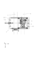
- FIG. 2 shows a plan view of the weight mounting facility 7 in the first embodiment.
- the equipment frame 20 of the weight mounting equipment 7 is disposed so as to straddle the pouring line 2 and the cooling line 3.
- the equipment frame 20 is provided with a cylinder 21 and a connecting frame 22.
- the connecting frame 22 fixes the jacket lifting device 5 and the weight lifting device 6 so as to be integrated.
- the jacket lifting / lowering device 5 and the weight lifting / lowering device 6 fixed by the connecting frame 22 move along the equipment frame 20 by the operation of the cylinder 21 (Y-axis direction in the figure). And it is comprised so that it can stop on the pouring line 2 and the cooling line 3.
- FIG. 1 shows a plan view of the weight mounting facility 7 in the first embodiment.
- the equipment frame 20 of the weight mounting equipment 7 is disposed so as to straddle the pouring line 2 and the cooling line 3.
- the equipment frame 20 is provided with a cylinder 21 and a connecting frame 22.
- the connecting frame 22 fixes the jacket lifting device 5 and the
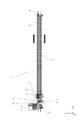
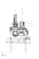
- FIG. 3 shows the structure of the weight mounting facility 7 in the first embodiment. Specifically, a structure in which the jacket lifting device 5 when positioned on the pouring line 2 and the weight lifting device 6 when positioned on the cooling line 3 are viewed from the right side is shown.
- the jacket elevating device 5 includes an elevating cylinder 14, a frame 15, and a jacket elevating claw 16.
- the elevating cylinder 14 is connected to the frame 15.
- the jacket raising / lowering claw 16 is provided on the frame 15.
- the jacket 12 has a flange 12a.
- the jacket lifting / lowering claw 16 engages with the collar portion 12 a and rises in the engaged state. Thereby, the jacket lifting / lowering device 5 can lift the jacket 12 placed on the mold 8 on the cooling line 3.
- the jacket elevating device 5 includes a deceleration position determining device 30.
- FIG. 5 shows the structure of the deceleration position determining device 30.
- the deceleration position determining device 30 includes a bar member 31, a first detector 32, and first proximity switches 33a, 33b, and 33c.
- a first frame 34 is disposed above the frame 15 in the jacket lifting device 5.
- first proximity switches 33a, 33b, and 33c are arranged at different heights.
- the first proximity switches 33a, 33b, and 33c are separated so as not to affect each other.
- the three first proximity switches are arranged in the order of the first proximity switches 33a, 33b, and 33c from the top.
- the bar member 31 is disposed so as to extend in the vertical direction of the jacket lifting device 5 (the height direction of the mold 8) (Z-axis direction in the figure).
- a first detector 32 is attached to one end of the bar member 31.
- the first detector 32 has a cylindrical shape with one end opened. As shown in FIG. 8, the first detection body 32 is attached to the rod member 31 so that the opening of the first detection body 32 faces downward.
- the height width of the first detector 32 (the length in the Z-axis direction in the figure) is set to be longer than the separation distance between the first proximity switches 33a and 33c. And when the jacket raising / lowering apparatus 5 raises / lowers the jacket 12, the other end of the bar member 31 and the collar part 12a contact
- Each of the three first proximity switches transmits a signal to a sequencer (not shown) when the first detector 32 moves up and down and is positioned at the same height.
- the movement of the deceleration position determining device 30 during the operation of the jacket lifting device 5 is shown below.
- Each of the three first proximity switches is disposed on the first frame 34.
- the first frame 34 is disposed on the frame 15 of the jacket lifting device 5. Therefore, the three first proximity switches move together with the jacket lifting device 5.
- the bar member 31 to which the first detection body 32 is attached is in contact with the jacket 12.
- the jacket 12 is lowered by the jacket lifting device 5. Therefore, the first detector 32 also moves with the jacket lifting device 5. Therefore, the positional relationship between the three first proximity switches and the first detector 32 does not change. In this case, the first detector 32 is located at a lower height than the three first proximity switches. For this reason, none of the three first proximity switches detects the first
- the movement of the deceleration position determining device 30 from when the jacket elevating device 5 covers the mold 8 on the pouring line 2 until the jacket 12 is lowered on the pouring line 2 is shown.
- the three first proximity switches move (lower) together with the jacket lifting device 5 as described above.
- the bar member 31 to which the first detection body 32 is attached is in contact with the jacket 12.
- the jacket 12 does not descend because it covers the mold 8. Therefore, the first detection body 32 does not move (lower) with the jacket elevating device 5. Therefore, when the first detector 32 is observed from the three first proximity switches, the first detector 32 appears to rise in height. As described above, the first detector 32 can be moved up and down relatively with respect to the jacket lifting device 5. Then, as shown in FIG.
- the height distance A1 of the first detection body 32 is a distance from the lower end of the flange 12a to the upper surface of the jacket lifting / lowering claw 16 when the jacket lifting / lowering claw 16 of the jacket lifting / lowering device 5 is located at the lower limit position on the pouring line 2. It is equal to the distance to A2.
- the first proximity switch and the first detector 32 need to approach each other to some extent. For this reason, the first proximity switch and the first detection body 32 are arranged such that the first proximity switch has a distance at which the first detection body 32 can be detected.
- the first detector 32 has a cylindrical shape. For this reason, even if the 1st detection body 32 rotates centering on the rod member 31, the 1st detection body 32 and the 1st proximity switch do not contact. And when the 1st detection body 32 is attached to the rod member 31, it attaches so that the opening of the 1st detection body 32 may become down. For this reason, impurities such as casting sand do not enter the first detection body 32. Furthermore, a hole through which impurities such as casting sand can pass may be provided in the upper part of the first detection body 32. Thereby, it is possible to prevent impurities from accumulating on the first detector 32.
- the stopper 35 is provided on the rod member 31 so that the rod member 31 and the first detector 32 do not fall more than necessary with respect to the frame 15.
- the weight lifting device 6 in the weight mounting facility 7 includes a lifting cylinder 17, a frame 18, and a weight lifting claw 19.
- the elevating cylinder 17 is connected to the frame 18.
- the weight lifting / lowering claw 19 is provided on the frame 18.
- the frame 18 and the weight lifting claw 19 of the weight lifting device 6 can be moved in the vertical direction by the lifting cylinder 17 (Z-axis direction in the figure).
- the weight lifting claw 19 engages with the weight 13 and rises in the engaged state.
- the weight lifting device 6 can lift the weight 13 placed on the upper surface of the mold 8 on the cooling line 3.
- the weight lifting device 6 is moved in the Y-axis direction in the figure by the operation of the cylinder 21, and the weight 13 lifted by the cooling line 3 can be placed on the upper surface of the mold 8 on the pouring line 2. .
- the weight lifting device 6 includes a deceleration position detection device 37.
- FIG. 7 shows the structure of the deceleration position detection device 37.
- the deceleration position detection device 37 includes a second detection body 38 and second proximity switches 36a, 36b, 36c, and 36d.
- the second proximity switches 36a, 36b, 36c, and 36d are disposed at different heights.
- the second proximity switches 36a, 36b, 36c, and 36d are separated so as not to affect each other.
- the four second proximity switches are arranged in the order of the second proximity switches 36a, 36b, 36c, and 36d from the top.
- the four second proximity switches are disposed on the second frame 39.
- the second frame 39 is disposed on the equipment frame 20 as shown in FIG. As described above, the second proximity switches 36 a, 36 b, 36 c, and 36 d are attached to the weight lifting device 6.
- the second detector 38 is disposed on the upper part of the weight side guide pin 40 that moves up and down in accordance with the lifting and lowering of the weight 13 by the weight lifting device 6.
- Each of the four second proximity switches transmits a signal to a sequencer (not shown) when the second detector 38 is moved up and down and positioned at the same height.
- the height of the upper frame and the lower frame in the mold 8 is assumed to be the same.
- the outer peripheral lower part of the upper frame and the outer peripheral upper part of the lower frame are both tapered, and the center of the outer periphery of the mold 8 becomes one tapered shape by combining the upper frame and the lower frame.
- the inner periphery of the jacket 12 has a tapered shape, and the jacket 12 covers the mold 8 because the outer periphery of the mold 8 and the inner periphery of the jacket 12 are combined.
- the center of the height of the jacket 12 is assumed to be located on the mating surface of the upper frame and the lower frame in the mold 8.
- the jacket elevating claw 16 is separated from the flange 12a and continues to descend to the lower limit position.
- the descent limit position indicates a position when the jacket raising / lowering claw 16 of the jacket raising / lowering device 5 has been lowered.
- the three first proximity switches continue to descend together with the jacket elevating device 5 until the jacket elevating claw 16 comes off the collar 12a and reaches the lower limit position.
- the first detector 32 is not displaced because it is in contact with the jacket 12 covered with the mold 8 via the rod member 31. Therefore, when the first detection body 32 is observed from the three first proximity switches, the first detection body 32 appears to rise.
- FIG. 8 shows an enlarged view of the deceleration position determining device 30.
- the height of the upper end of the first detection body 32 before the jacket 12 covers the mold 8 is defined as a height ⁇ .
- the first proximity switches 33a, 33b, and 33c are positioned at heights that are separated from the height ⁇ by distances Da, Db, and Dc, respectively.
- FIG. 9 shows the positional relationship between the jacket elevating device 5 and the jacket 12 in a state where the jacket elevating claw 16 of the jacket elevating device 5 has reached the lower limit position.
- a method for determining the deceleration position of the weight 13 in the descending direction of the weight lifting device 6 will be described.
- a method for determining the deceleration position of the weight 13 when the weight 13 is placed on the molds 8H, 8N, and 8L having three different heights H, N, and L will be described.
- a method for determining the deceleration position of the weight 13 when the mold 8 is not placed on the platen carriage 9 will also be described.
- the deceleration position is a position where the weight 13 descending at the first descending speed starts to decelerate.
- the upper surface height of the jacket raising / lowering claw 16 at the lowering limit is defined as the lowering limit height ⁇ .
- the three different heights are set lower in the order of height H> N> L.
- the jacket raising / lowering claw 16 is lowered by a distance h from the time when the jacket raising / lowering claw 16 is disengaged from the collar 12a until reaching the lower limit position.
- the first detection body 32 rises from the height ⁇ by the distance h as in the case of the jacket lifting / lowering claw 16.
- the distance h is longer than the distance Da in FIG. That is, the upper end of the first detection body 32 is positioned above the first proximity switch 33a when the jacket elevating claw 16 of the jacket elevating device 5 reaches the lowering limit position.
- the heights of the three first proximity switches 33a, 33b, 33c are all at the upper end of the first detector 32. It is located so that it is within the range of the lower end.
- each of the three first proximity switches 33a, 33b, 33c detects the first detection body 32 and transmits a signal to the sequencer. By transmitting a signal to the sequencer as described above, the deceleration position of the weight 13 when the weight 13 is placed on the mold 8H is determined.
- the operation of the jacket lifting / lowering device 5 and the deceleration position determining device 30 in the deceleration position determining step when the weight 13 is placed on the mold 8N shown in FIG. 9B will be described.
- the first detector 32 has a height ⁇ as viewed from the three first proximity switches, as described in the mold 8H. From the distance n.
- the distance n is longer than the distance Db in FIG. 8 and shorter than the distance Da. That is, the upper end of the first detection body 32 is located between the first proximity switches 33a and 33b.
- the two first proximity switches 33b and 33c When the first detection body 32 rises from the height ⁇ by a distance n with respect to the three first proximity switches, the heights of the two first proximity switches 33b and 33c become the upper and lower ends of the first detection body 32, respectively. It is located within the range. Therefore, when the jacket lifting / lowering claw 16 of the jacket lifting / lowering device 5 reaches the lowering limit position, the two first proximity switches 33b and 33c each detect the first detection body 32 and transmit a signal to the sequencer. By transmitting a signal to the sequencer as described above, the deceleration position of the weight 13 when the weight 13 is placed on the mold 8N is determined.
- the operation of the jacket lifting / lowering device 5 and the deceleration position determining device 30 in the deceleration position determining step when the weight 13 is placed on the mold 8L shown in FIG. 9C will be described.
- the first detector 32 has a height ⁇ as viewed from the three first proximity switches, as described in the mold 8H. Ascend a distance 1 from
- the distance l is longer than the distance Dc in FIG. 8 and shorter than the distance Db. That is, the upper end of the first detection body 32 is located between the first proximity switches 33b and 33c.
- the height of one first proximity switch 33c is within the range between the upper end and the lower end of the first detector 32. Located to fit in. Therefore, when the jacket lifting / lowering claw 16 of the jacket lifting / lowering device 5 reaches the lowering limit position, one first proximity switch 33c detects the first detection body 32 and transmits a signal to the sequencer. By transmitting a signal to the sequencer as described above, the deceleration position of the weight 13 when the weight 13 is placed on the mold 8L is determined.
- the operation of the jacket lifting / lowering device 5 and the deceleration position determining device 30 in the deceleration position determining step when the mold 8 does not exist on the platen carriage 9 as shown in FIG. 9 (D) will be described.
- the first detector 32 has a height ⁇ as viewed from the three first proximity switches, as described in the mold 8H. From the distance e.
- the distance e is shorter than the distance Dc. That is, the upper end of the first detection body 32 is located below the first proximity switch 33c.
- the heights of the three first proximity switches are all higher than the upper end of the first detector 43. Located at a high position. Therefore, when the jacket lifting / lowering claw 16 of the jacket lifting / lowering device 5 reaches the lowering limit position, none of the three first proximity switches detects the first detector 32 and transmits a signal to the sequencer. The deceleration position of the weight 13 is determined by not transmitting a signal from the first proximity switch to the sequencer in the deceleration position determination step.
- the mold 8 does not exist on the surface plate carriage 9
- the jacket 12 is placed directly on the surface plate carriage 9, as shown in FIG.
- the jacket lifting / lowering claw 16 of the jacket lifting / lowering device 5 After the jacket lifting / lowering claw 16 of the jacket lifting / lowering device 5 reaches the lowering limit, the jacket lifting / lowering device 5 is lifted again so as not to contact the mold 8 and the jacket 12. Thereafter, the jacket elevating device 5 is moved onto the cooling line 3 by the cylinder 21. Then, the mold 8 placed on the surface plate carriage 9 is intermittently conveyed by one pitch (one mold) by the surface plate carriage transfer equipment 4 in the state of a continuous mold group. The four different distances become shorter in the order of distance h> n> l> e. When the jacket lifting / lowering claw 16 of the jacket lifting / lowering device 5 reaches the lowering limit position, the jacket lifting / lowering claw 16 and the flange portion 12a do not contact in any of the above cases.
- Step 3 First weight lowering step
- the weight 13 placed on the mold 8 on the cooling line 3 is lifted by the weight lifting device 6 and moved onto the mold 8 on the pouring line 2. Thereafter, the weight 13 is lowered toward the mold 8.
- the descending speed of the weight lifting device 6 at this time is defined as a first descending speed.
- the first descending speed is higher than the second descending speed described later.
- the first lowering speed is set in consideration of the load on the weight lifting device 6 and the time from when the weight 13 is lowered to the second lowering speed.
- the deceleration position of the weight lifting device 6 is set by a signal transmitted to the sequencer by the three first proximity switches.
- the flow of setting the deceleration position for the molds 8H, 8N, and 8L having the heights H, N, and L, which are three different heights, will be described.
- a flow for setting the deceleration position when the mold 8 is not placed on the surface plate carriage 9 (when only the jacket 12 is placed) will be described.
- the height of the second detection body 38 before the weight lifting device 6 lowers the weight 13 is defined as a height ⁇ .
- the second proximity switches 36a, 36b, 36c, 36d are positions where the second detector 38 can be detected, and the second detector 38 is at the same height as the second proximity switches 36a, 36b, 36c, 36d.
- the positions are set as positions P1, P2, P3, and P4, respectively.
- FIG. 10 shows the deceleration position of the weight lifting device 6.
- Table 1 shows the relationship between the signal transmitted by the first proximity switch and the position of the second detector 38 in the first embodiment.
- the “presence / absence of signal transmitted by first proximity switch” column in Table 1 indicates whether or not the three first proximity switches 33a, 33b, and 33c transmit signals to the sequencer in the deceleration position determination step. Described for each type (mold height).
- “ ⁇ ” indicates that a signal is transmitted in the deceleration position determination step
- “ ⁇ ” indicates that no signal is transmitted.
- the “second detection body position” column indicates the position of the second detection body 38 when the weight lifting device 6 starts to decelerate.
- the type of signal transmitted from the first proximity switch to the sequencer differs depending on the mold height, and the deceleration position of the second detector 38 corresponding to the type of signal is set in advance. Yes. Specifically, when the three first proximity switches 33a, 33b, and 33c transmit signals to the sequencer, the second proximity switch 36a detects the second detector 38 (the second detector 38 is at the position P1). Once positioned), the weight lifting device 6 starts to decelerate. When the two first proximity switches 33b and 33c transmit signals to the sequencer, when the second proximity switch 36b detects the second detection body 38 (when the second detection body 38 is positioned at the position P2), the weight is lifted and lowered. The device 6 is decelerated.
- the weight is raised or lowered.
- Device 6 begins to decelerate.
- the first proximity switch does not transmit a signal to the sequencer in the deceleration position determination step
- the second proximity switch 36d detects the second detection body 38 (when the second detection body 38 is positioned at the position P4)
- the weight is raised or lowered.
- Device 6 begins to decelerate.
- the deceleration position is set to a higher position in the order of P1> P2> P3> P4. The higher the deceleration position is, the shorter the section that descends at the first descending speed.
- the weight lifting device 6 that has started decelerating then continues to descend at the second descending speed until the weight 13 is placed on the mold 8 or the jacket 12.
- the second descending speed is lower than the first descending speed.
- the second descending speed can be arbitrarily set as long as it is a speed that does not cause the mold 8 to collapse due to an impact when the weight 13 is placed on the mold 8.
- the weight lifting device 6 After the weight lifting device 6 places the weight 13 on the mold 8 (or the jacket 12) while maintaining the second descending speed, the weight lifting device 6 moves down a certain distance and stops. Then, the weight lifting device 6 is raised again so as not to contact the mold 8 and the weight 13. Thereafter, in order to repeat the above steps, the weight lifting device 6 is moved onto the cooling line 3 by the cylinder 21.
- the height of the upper frame and the lower frame in the mold 8 is the same, and the center of the height of the jacket 12 is located on the mating surface of the upper frame and the lower frame.
- the distance from the lower surface of the flange 12a to the lower limit height ⁇ is the same as the distance by which the first detector 32 rises from the height ⁇ in the deceleration position determination step. Therefore, in the deceleration position determination step, the greater the height value of the mold 8, the longer the distance from the lower surface of the flange 12a to the lower limit height ⁇ , and the distance that the first detector 32 rises from the height ⁇ . Also gets longer.
- a method for setting the height positions of the first proximity switches 33a, 33b, 33c and the second proximity switches 36a, 36b, 36c, 36d will be described below.
- the first proximity switches 33a, 33b, 33c and the second proximity switches 36a, 36b, 36c, 36d are all separated so as not to affect each other.
- a decelerating position determination step is performed in advance on the mold 8M having the maximum height and the mold 8m having the minimum height among molds that can be molded by the frame making machine 10, and the upper end height position of the first detector 32 is confirmed.
- the upper end heights of these first detection bodies 32 are indicated as PM and Pm in FIG.
- the two first proximity switches 33a and 33b are arranged within the range of the upper end heights PM and Pm.
- the height of the mold 8M is set as H +, and the height of the mold 8m is set as L-.
- the deceleration position determining step is performed in the same manner, and the upper end height position of the first detection body 32 is confirmed.
- the upper end height of the first detector 32 is indicated as Pn in FIG.
- one first proximity switch 33c is arranged within the range of the upper end heights Pm and Pn.
- the first proximity switch 33b is disposed at an intermediate position between the first proximity switches 33a and 33c.
- the three first proximity switches 33a, 33b, and 33c can be arranged at arbitrary positions within the above-described range.
- the template when the first detector 32 is raised by the distance Da is the template 8Da having the template height M +
- the template when the first detector 32 is raised by the distance Db is the template height.
- a template 8Db having a thickness L + is used.
- the position of the second proximity switch 36a is set so that the weight 13 can be placed at the second descending speed when the weight 13 is placed on the mold 8M. Specifically, only the distance necessary to decelerate from the first descending speed to the second descending speed from the position of the second detector 38 at the moment when the weight 13 is placed on the mold 8M having the mold height H +.
- the position of the second proximity switch 36a is set so that the upper position becomes the position P1.
- the position of the second proximity switch 36b is set so that it can be placed at the second descending speed when the weight 13 is placed on the mold 8Da. Specifically, only the distance necessary to decelerate from the first descending speed to the second descending speed from the position of the second detector 38 at the moment when the weight 13 is placed on the mold 8Da having the mold height M +.
- the position of the second proximity switch 36b is set so that the upper position becomes the position P2.
- the position of the second proximity switch 36c is set so that the weight 13 can be placed at the second descending speed when the weight 13 is placed on the mold 8Db. Specifically, only the distance necessary for decelerating from the first descending speed to the second descending speed from the position of the second detector 38 at the moment when the weight 13 is placed on the mold 8Db having the mold height L +.
- the position of the second proximity switch 36c is set so that the upper position becomes the position P3.
- the position of the second proximity switch 36d is set so that the weight 13 can be placed at the second descending speed when the weight 13 is placed on the jacket 12.
- the position above the position of the second detector 38 at the moment when the weight 13 is placed on the jacket 12 is a position P4 that is a distance necessary to decelerate from the first descending speed to the second descending speed.
- the position of the second proximity switch 36d is set so that
- Table 1 summarizes the relationship between the mold height and the deceleration position of the second detector 38.
- the height H is in the range of heights M + to H +
- the height M is in the range of heights L + to M +
- the height L is in the range of heights L ⁇ to L +.
- the deceleration position is determined in consideration of the height of the mold on which the weight 13 is placed.
- the deceleration position may be determined in consideration of the mechanical load on the weight lifting device 6 when the lowering speed of the weight lifting device is decreased from the first lowering speed to the second lowering speed.
- the two first proximity switches 33a and 33b are arranged in the range of the upper end heights PM and Pm.
- the present invention is not limited to this, and one or three or more first proximity switches are arranged. You may do it.
- a second proximity switch other than the above four may be arranged based on a method for setting the height position of the second proximity switch.
- the steps from lowering the weight 13 by the weight lifting device 6 to placing it on the mold 8 are the first weight lowering step of lowering the weight 13 at the first lowering speed. And a second double weight lowering step of lowering the weight 13 at the second lowering speed.
- the weight 13 is placed at a speed without breaking the mold 8 having an arbitrary height, and the descent time of the weight 13 due to the second descent speed, which is lower than the first descent speed, is minimized. Since it is possible to limit to the limit, the process time is shortened.
- the deceleration position determination device 30 determines a deceleration position that is a position for changing from the first descending speed to the second descending speed for each mold 8 flowing in the pouring line 2. With this configuration, the deceleration position is determined for each mold 8 flowing in the pouring line 2, so that it is possible to cope with casting molds having different heights flowing in the pouring line 2. That is, according to this embodiment, since the height of the mold on which the weight is placed can be set arbitrarily, it is possible to cope with a change in the height of the mold.
- both the deceleration position determination device 30 and the deceleration position detection device 37 include a plurality of proximity switches. Since the proximity switch can be easily removed, when a trouble such as breakage occurs, it is possible to promptly replace the proximity switch.
- a weight mounting facility including an optical measurement unit as a deceleration position determination device will be described as a second embodiment.
- a laser sensor is used as the optical measurement means.
- the weight mounting facility 107 includes a weight lifting device 106, and is disposed across the pouring line and the cooling line.
- a jacket elevating device 105 is disposed on the upstream side of the pouring line as viewed from the weight elevating device 106 so as to straddle the pouring line and the cooling line.
- the jacket lifting / lowering device 105 has the same configuration as the jacket lifting / lowering device 5 in the first embodiment except that it does not include the deceleration position determination device 30.
- FIG. 11 shows the configuration of the weight lifting device 106 in the second embodiment.
- the weight lifting device 106 includes a lifting cylinder (not shown), a frame 118, a weight lifting claw 119, and a frame 150.
- the frame 150 has a cylindrical shape, and the lifting cylinder is disposed so as to be surrounded by the frame 150.
- the lifting cylinder is connected to the frame 118.
- the weight lifting / lowering claw 119 is provided on the frame 118.
- the frame 118 and the weight lifting claw 119 of the weight lifting device 106 can be moved up and down by the lifting cylinder (Z-axis direction in the figure). When lifting the weight 13, the weight lifting claw 119 engages with the lower surface of the weight 13 and rises in the engaged state.
- the weight lifting apparatus 106 can lift the weight 13 placed on the upper surface of the mold 8 on the cooling line.
- the weight lifting device 106 can place the weight 13 lifted by the cooling line on the upper surface of the mold 8 on the pouring line.
- the frame 150 is integrated with the weight lifting device 106 and is moved in the vertical direction by the lifting cylinder together with the weight lifting device 106.
- the weight lifting device 106 includes two laser sensors 130 as a deceleration position determining device.
- the two laser sensors 130 are attached to the frame 150 and are arranged so as to emit laser light perpendicular to the horizontal plane (the upper surface of the mold).
- the laser sensor 130 can continuously measure the distance from the laser sensor 130 to the mold 8 by receiving the laser light reflected from the mold 8. Then, the measured distance is transmitted to a sequencer (not shown) as needed.
- the jacket 12 is previously placed on the mold 8 on the pouring line by the jacket lifting device 105.
- the mold 8 covering the jacket 12 is located below the weight lifting device 106.
- the weight 13 placed on the mold 8 on the cooling line is lifted by the weight lifting device 106 and moved to the mold 8 on the pouring line. Thereafter, the weight 13 is lowered by the weight lifting device 106.
- Each of the two laser sensors 130 emits laser light vertically toward the upper surface of the mold 8 and starts measuring the distance from the laser sensor 130 to the upper surface of the mold 8 (measurement process). In this measurement process, the distance is continuously measured from when the weight 13 starts being lowered by the weight lifting device 106 until it is placed on the mold 8, and the measurement result is transmitted to the sequencer. Yes. Note that when the weight lifting device 106 is descending the weight 13, the two laser sensors 130 are attached to the frame 150, and thus move together with the weight lifting device 106. On the other hand, the mold 8 is placed on a pouring line. Therefore, the laser sensor 130 approaches the mold 8 over time.
- the distance PS from the laser sensor 130 to the upper surface of the mold 8 when the weight lifting device 106 starts decelerating from the first lowering speed to the second lowering speed is set in advance.
- the deceleration position of the weight lifting device 106 is determined and the deceleration is started. (Deceleration position determination step). It should be noted that the weight 13 descending process by the weight lifting device 106 includes the process of descending at the first descending speed from the start of the descending to the deceleration position (first weight descending process), and the mold 8 from the deceleration position.
- the distance PS in the second embodiment is arbitrarily set in consideration of the deceleration distance from the first descending speed to the second descending speed.
- the weight lifting device 106 starts decelerating when the smaller value of the distances continuously measured by the two laser sensors 130 becomes the distance PS. This is because the case where the laser light emitted from one laser sensor 130 hits the gate on the upper surface of the mold 8 is taken into consideration.
- the laser light emitted from the laser sensor 130 strikes the surface plate carriage.
- the distance measured by the laser sensor 130 when the weight 13 starts to descend is significantly longer than when the mold 8 is placed on the platen carriage.
- the sequencer determines that only the jacket 12 is placed on the surface plate carriage.
- the deceleration position of the weight 13 is set to a position above the upper surface of the flange portion 12a of the jacket 12 by a distance necessary to decelerate from the first descending speed to the second descending speed.
- the weight lifting device 106 After placing the weight 13 on the mold 8 (or on the jacket 12), the weight lifting device 106 is lowered by a certain distance and stopped. Then, the weight lifting device 106 is lifted so as not to contact the mold 8 and the weight 13. Thereafter, the weight lifting device 106 moves over the cooling line to repeat the process.
- the deceleration position determination device is only two laser sensors 130, and does not have a deceleration position detection device. Therefore, a simple equipment configuration can be achieved.
- the number of times the weight is decelerated by the weight lifting device is set to one time, but the number of times of deceleration may be divided into two or more times to decelerate the weight in stages. Thereby, the mechanical load of the weight lifting apparatus can be suppressed.
- the weight lifting device 6 is set to decelerate when the second proximity switches 36a and 36c detect the second detector 38, respectively. May be.
- SYMBOLS 1 Frame making line, 5,105 ... Jacket raising / lowering device, 6,106 ... Weight raising / lowering device, 7,107 ... Weight mounting equipment, 8 ... Mold, 12 ... Jacket, 12a ... Gutter part, 13 ... Heavy Weight ... 30 ... Deceleration position determination device, 31 ... Bar member, 32 ... First detector, 33a, 33b, 33c ... First proximity switch, 36a, 36b, 36c, 36d ... Second proximity switch, 37 ... Deceleration position detection Device: 38 ... second detector, 106 ... weight lifting device, 130 ... laser sensor (light measuring means).
Landscapes
- Engineering & Computer Science (AREA)
- Mechanical Engineering (AREA)
- Casting Devices For Molds (AREA)
- Moulds For Moulding Plastics Or The Like (AREA)
Abstract
重錘を下降させて鋳型の上に載置させる重錘昇降装置6と、重錘昇降装置における重錘の下降方向の減速位置を決定する減速位置決定装置30と、を具備しており、重錘昇降装置6における重錘の下降速度は、下降を開始してから減速位置に到達するまでの第一下降速度と、減速位置から鋳型の上に載置されるまでの第二下降速度と、を含み、第二下降速度は、第一下降速度よりも低速である。
Description
本開示は、抜枠造型ラインの鋳型の上に重錘を載置する、重錘載置設備及び重錘載置方法に関するものである。
鋳枠のない砂鋳型を用いて鋳造を行う抜枠造型法では、注湯された溶湯による鋳型の浮き上がりを防止するために、鋳型の外周にテーパー状のジャケットを被せるとともに、鋳型の上に重錘が載置される。溶湯が凝固した後、ジャケットや重錘は鋳型から取り外され、鋳造された製品が取り出される。
特許文献1には、抜枠造型ラインにおける、重錘ジャケット移し変え装置に関する記載がある。特許文献1記載の重錘ジャケット移し変え装置は、冷却ライン上の鋳型から重錘を取り外し、注湯ライン上の鋳型上に重錘を設置する。そして、冷却ライン上の鋳型からジャケットを取り外し、注湯ライン上の鋳型上にジャケットを被せる。
特許文献1記載の注湯ライン及び冷却ラインは平行に配置されており、重錘ジャケット移し変え装置は注湯ラインと冷却ラインを跨いで配置されている。そのため、重錘及びジャケットの移し変えのために必要な空間を抑えることができる。
しかし、重錘が下降を開始してから鋳型の上に載置されるまでの重錘の下降速度は、重錘を鋳型の上に載置した時の衝撃で鋳型が崩壊しない程度の速度に設定されている。この速度は低速であるため、重錘が下降を開始してから鋳型の上に載置されるまでのサイクルタイムが長くなってしまう。
上記の課題に鑑み、本開示は抜枠造型ラインにおける重錘載置設備及び重錘載置方法を提供することを目的とする。
上記の目的を達成するために、本開示の一形態は、抜枠造型ライン上の鋳型に重錘を載置する重錘載置設備であって、前記重錘を下降させて前記鋳型の上に載置させる重錘昇降装置と、前記重錘昇降装置における前記重錘の下降方向の減速位置を決定する減速位置決定装置と、を具備しており、前記重錘昇降装置における前記重錘の下降速度は、下降を開始してから前記減速位置に到達するまでの第一下降速度と、前記減速位置から前記鋳型の上に載置されるまでの第二下降速度と、を含み、前記第二下降速度は、前記第一下降速度よりも低速である。
減速位置決定装置は、重錘昇降装置における重錘の下降方向の減速位置を決定する。重錘は重錘昇降装置によって、鋳型の上に載置するために下降される。この際、重錘の下降速度は、下降を開始してから減速位置まで到達するまでの区間(第一区間)と、減速位置から鋳型の上に載置されるまでの区間(第二区間)とで、異なるように設定される。第二区間の重錘の下降速度(第二下降速度)は、重錘を載置した時の衝撃で鋳型が崩壊しない程度の速度に設定される。つまり、第一区間の重錘の下降速度(第一下降速度)は、第二下降速度よりも速い速度で設定される。
本形態によれば、第一下降速度で重錘を下降させる区間を設定することにより、第二下降速度で重錘を下降させる時間を短くすることが可能となる。よって、本形態によれば、重錘の下降を開始してから重錘を鋳型の上に載置させるまでのサイクルタイムを短くすることができる。
一実施形態では、重錘載置設備は、前記重錘昇降装置の上流に配置される、ジャケットを前記鋳型の側面に被せるジャケット昇降装置を更に具備してもよい。前記減速位置決定装置は、前記ジャケット昇降装置に配設されてもよい。この形態によれば、重錘昇降装置の上流に具備しているジャケット昇降装置が動作している際に減速位置決定装置が動作し、重錘昇降装置における重錘の下降方向の減速位置を決定することができる。
一実施形態では、前記減速位置決定装置は、前記重錘昇降装置に配設される、光により前記鋳型の上面までの距離を計測する光計測手段を具備してもよい。前記光計測手段は、該光計測手段から放射された光が、前記鋳型の上面に垂直に当たるように配設されてもよい。この場合、重錘昇降装置に備えられている光計測手段により、重錘昇降装置から鋳型の上面までの距離が計測される。そして、計測された距離を基に、減速位置決定装置により減速位置が決定される。この形態によれば、鋳型の上面までの距離の計測と重錘の減速位置の決定とを、光計測手段という一つの装置で行うことができる。
一実施形態では、前記減速位置決定装置は、前記ジャケット昇降装置に対して相対的に昇降可能である第一検出体と、前記ジャケット昇降装置と共に昇降し、前記第一検出体を検出する第一近接スイッチと、を具備してもよい。前記第一近接スイッチは、異なる前記鋳型の高さに対応する複数の近接スイッチを備えていてもよい。
一実施形態では、前記重錘昇降装置は、前記減速位置を検知する減速位置検知装置を具備してもよい。前記減速位置検知装置は、前記重錘昇降装置の昇降動作に伴って昇降する第二検出体と、前記重錘昇降装置に装着され、前記第二検出体を検出する第二近接スイッチと、を具備してもよい。前記第二近接スイッチは、異なる前記鋳型の高さに対応する複数の近接スイッチを備えていてもよい。近接スイッチは交換が容易であるため、破損等の不具合時に迅速な対応が可能となる。よって、この形態によれば整備性に優れた重錘載置設備となる。
一実施形態では、前記減速位置決定装置は、前記鋳型の高さ方向に延伸している棒部材を更に具備してもよい。前記棒部材の上端には、前記第一検出体が配設されており、前記棒部材の下端は前記ジャケットに形成されている鍔部に当接可能に配置されていてもよい。この形態によれば、簡便な構造で減速位置の決定が可能となる。
一実施形態では、前記第一検出体は、前記鋳型の高さ方向に延伸しており、下端が開口している円筒形状でもよい。仮に第一検出体の形状を上端が開口している円筒形状とすると、第一検出体の内部に鋳物砂が入ってしまう。また、第一検出体の形状を円柱形状とすると、第一検出体の材料費用が高額になってしまう。この形態によれば、第一検出体は、内部に鋳物砂が入ることなく、且つ、材料費用を安く抑えることが可能となる。
本開示の他の形態は、上述した抜枠造型ライン上の鋳型に重錘を載置する方法であって、前記ジャケット昇降装置により、前記ジャケットを下降させて前記鋳型の側面に被せるジャケット被せ工程と、前記減速位置決定装置により、前記重錘昇降装置における前記重錘の下降方向の前記減速位置を決定する減速位置決定工程と、前記重錘昇降装置により、前記減速位置まで前記重錘を前記第一下降速度で下降させる第一重錘下降工程と、前記重錘昇降装置により、前記減速位置から前記鋳型に前記重錘を載置するまで、前記重錘を前記第二下降速度で下降させる第二重錘下降工程と、を有する。この重錘載置方法では、第一検出体と第一近接スイッチとによって重錘の減速位置が決定され、その減速位置で重錘の下降速度が低下し、重錘が鋳型の上に載置される。このため、この重錘載置方法は、任意の高さを有する鋳型の上に重錘を載置することができる。なお、この重錘載置方法においては、各工程を順番に実施してもよいし、2つ以上の工程を同時に実施してもよい。
本開示のさらに他の形態は、上述した抜枠造型ライン上の鋳型に重錘を載置する方法であって、前記光計測手段により、該光計測手段から前記鋳型の上面までの距離を計測する計測工程と、前記計測工程で計測された距離に基づいて、前記重錘昇降装置における前記重錘の下降方向の減速位置を決定する減速位置決定工程と、前記重錘昇降装置により、前記減速位置まで前記重錘を前記第一下降速度で下降させる第一重錘下降工程と、前記重錘昇降装置により、前記減速位置から前記鋳型に前記重錘を載置するまで、前記重錘を前記第二下降速度で下降させる第二重錘下降工程と、を有する。この重錘載置方法では、光計測手段によって計測した距離に基づいて重錘の減速位置が決定され、その減速位置で重錘の下降速度が低下し、重錘が鋳型の上に載置される。このため、この重錘載置方法は、任意の高さを有する鋳型の上に重錘を載置することができる。なお、この重錘載置方法においては、各工程を順番に実施してもよいし、2つ以上の工程を同時に実施してもよい。
本開示の種々の側面及び実施形態によれば、重錘昇降装置によって重錘を下降する際、第一下降速度で下降する第一区間と第二下降速度で下降する第二区間を設定しているため、全区間を第二下降速度で下降する場合と比べて、重錘の下降を開始してから重錘を鋳型の上に載置させるまでのサイクルタイムを短くすることができる。
重錘載置設備の実施形態の一例を、図面を参照して説明する。以下の説明において上下左右方向は特に断りのない限り図中における方向を指す。なお、本発明は本実施形態の構成に限られず、必要に応じて適宜変更することができる。また、各実施形態における鋳型とは、特に断りのない限り、鋳物砂によって作成され、上枠と下枠が合わさったものを指す。
(第一実施形態)
図1に、第一実施形態における抜枠造型ライン1の全体構成を示す。図1に示すように、注湯ライン2と冷却ライン3とが図中のX軸方向に沿って平行に配置され、その両端に定盤台車移送設備(プッシャー装置、クッション装置及びトラバーサー)4が配置される。これにより、鋳型8を載せて搬送する定盤台車9が循環できる。抜枠造型ライン1は、定盤台車9を一定時間ごとにピッチ送りするコンベヤにより構成されている。そして、抜枠造型機10は、抜枠造型機10で造型された鋳型8が搬入位置11から注湯ライン2に搬入できるように配置されている。ジャケット昇降装置5と重錘昇降装置6とを備えている重錘載置設備7は、注湯ライン2と冷却ライン3とを跨ぐように配置されている。図1中に記す矢印は、定盤台車9及び定盤台車9上に載置している鋳型8の進行方向を示している。
図1に、第一実施形態における抜枠造型ライン1の全体構成を示す。図1に示すように、注湯ライン2と冷却ライン3とが図中のX軸方向に沿って平行に配置され、その両端に定盤台車移送設備(プッシャー装置、クッション装置及びトラバーサー)4が配置される。これにより、鋳型8を載せて搬送する定盤台車9が循環できる。抜枠造型ライン1は、定盤台車9を一定時間ごとにピッチ送りするコンベヤにより構成されている。そして、抜枠造型機10は、抜枠造型機10で造型された鋳型8が搬入位置11から注湯ライン2に搬入できるように配置されている。ジャケット昇降装置5と重錘昇降装置6とを備えている重錘載置設備7は、注湯ライン2と冷却ライン3とを跨ぐように配置されている。図1中に記す矢印は、定盤台車9及び定盤台車9上に載置している鋳型8の進行方向を示している。
図2に、第一実施形態における重錘載置設備7の平面図を示す。注湯ライン2と冷却ライン3を跨ぐように、重錘載置設備7の設備フレーム20が配置されている。設備フレーム20には、シリンダ21と連結フレーム22とが配置されている。連結フレーム22は、ジャケット昇降装置5と重錘昇降装置6とを一体とするように固定している。連結フレーム22によって固定されているジャケット昇降装置5と重錘昇降装置6とは、シリンダ21の動作により設備フレーム20上に沿って移動する(図中のY軸方向)。そして、注湯ライン2上及び冷却ライン3上で停止することができるように構成されている。
図3に、第一実施形態における重錘載置設備7の構造を示す。具体的には、注湯ライン2上に位置したときのジャケット昇降装置5と、冷却ライン3上に位置したときの重錘昇降装置6とを、それぞれ右側面から視た構造を示す。
ジャケット昇降装置5は、昇降シリンダ14とフレーム15とジャケット昇降爪16とを備えている。昇降シリンダ14は、フレーム15に接続される。ジャケット昇降爪16は、フレーム15に設けられる。昇降シリンダ14によって、ジャケット昇降装置5のフレーム15及びジャケット昇降爪16は上下方向に移動することができる(図中のZ軸方向)。ジャケット12には、鍔部12aが形成されている。ジャケット12を持ち上げる際、ジャケット昇降爪16は、鍔部12aに係合し、係合した状態で上昇する。これにより、ジャケット昇降装置5は、冷却ライン3上の鋳型8に被せられたジャケット12を持ち上げることができる。そして、ジャケット昇降装置5は、シリンダ21の動作により図中のY軸方向へ移動し、注湯ライン2上の鋳型8に、冷却ライン3にて持ち上げたジャケット12を降ろして被せることができる。
図3に示すように、ジャケット昇降装置5は減速位置決定装置30を備えている。図5に、減速位置決定装置30の構造を示す。減速位置決定装置30は、棒部材31と、第一検出体32と、第一近接スイッチ33a、33b、33cとを備えている。ジャケット昇降装置5におけるフレーム15の上部には第一フレーム34が配設されている。第一フレーム34には第一近接スイッチ33a、33b、33cが、それぞれ異なる高さの部分に配設されている。第一近接スイッチ33a、33b、33cは、相互に影響しない程度に離間している。3つの第一近接スイッチは、上から第一近接スイッチ33a、33b、33cの順番で配置されている。
棒部材31は、ジャケット昇降装置5の上下方向(鋳型8の高さ方向)に延伸するように配設される(図中のZ軸方向)。棒部材31の一端には、第一検出体32が取り付けられている。第一検出体32は、その一端が開口している円筒形状を有している。第一検出体32は、図8に示すように、第一検出体32の開口が下になるように棒部材31に取り付けられる。第一検出体32の高さの幅(図中のZ軸方向の長さ)は、第一近接スイッチ33aと33cとの離間距離よりも長く設定される。そして、ジャケット昇降装置5がジャケット12を昇降している際、棒部材31の他端と鍔部12aとが当接される。
3つの第一近接スイッチはそれぞれ、第一検出体32が昇降して同じ高さに位置するとき、信号をシーケンサ(図示せず)に送信する。
ジャケット昇降装置5の動作時の、減速位置決定装置30の動きを以下に示す。まず、ジャケット昇降装置5が冷却ライン3上の鋳型8に被せられたジャケット12を持ち上げてから、注湯ライン2上の鋳型8にジャケット12を被せるまでの、減速位置決定装置30の動きを示す(図5参照)。3つの第一近接スイッチそれぞれは、第一フレーム34に配設されている。第一フレーム34は、ジャケット昇降装置5のフレーム15に配設されている。そのため、3つの第一近接スイッチは、ジャケット昇降装置5と共に移動する。第一検出体32が取り付けられている棒部材31は、ジャケット12に当接している。ジャケット12はジャケット昇降装置5によって下降する。そのため、第一検出体32もジャケット昇降装置5と共に移動する。よって、3つの第一近接スイッチと第一検出体32との位置関係は変わらない。なお、この場合、第一検出体32は3つの第一近接スイッチよりも低い高さに位置している。このため、3つの第一近接スイッチはいずれも第一検出体32を検出しない。
次に、ジャケット昇降装置5が注湯ライン2上の鋳型8にジャケット12を被せてから、注湯ライン2上で下がりきるまでの、減速位置決定装置30の動きを示す。3つの第一近接スイッチは、先の説明と同様、ジャケット昇降装置5と共に移動(下降)する。一方、第一検出体32が取り付けられている棒部材31は、ジャケット12に当接している。ジャケット12は、鋳型8に被さっているため下降しない。そのため、第一検出体32はジャケット昇降装置5と共に移動(下降)しない。よって、第一検出体32は、3つの第一近接スイッチ側から観察すると、高さが上昇しているように見える。このように、第一検出体32は、ジャケット昇降装置5に対して相対的に昇降可能である。そして、図6に示すように、ジャケット昇降装置5のジャケット昇降爪16が下がりきった時(ジャケット昇降爪16が下降限界位置に位置した時)、第一検出体32が初期位置から移動した高さ距離A1に応じて、3つの第一近接スイッチが第一検出体32を検出し、信号をシーケンサに送信する。第一検出体32の高さ距離A1は、ジャケット昇降装置5のジャケット昇降爪16が注湯ライン2上で下降限界位置に位置した時における、鍔部12a下端からジャケット昇降爪16上面までの距離A2との距離と、等しい。
第一近接スイッチが第一検出体32を検出するためには、第一近接スイッチと第一検出体32とがある程度の距離近づく必要がある。このため、第一近接スイッチが第一検出体32を検出できる距離となるように、第一近接スイッチと第一検出体32とが配置される。本実施形態において、第一検出体32は円筒形状である。このため、第一検出体32が棒部材31を中心に回転したとしても、第一検出体32と第一近接スイッチとが接触しない。そして、第一検出体32が棒部材31に取り付けられる際、第一検出体32の開口が下になるように取り付けられる。このため、第一検出体32の中に鋳砂等の不純物が入らない。さらに、第一検出体32の上部に、鋳砂等の不純物が通り抜けることが可能な孔を設けてもよい。これにより、第一検出体32の上に不純物が積もってしまうことを防ぐことができる。
さらに、本実施形態においては、棒部材31及び第一検出体32がフレーム15に対して必要以上に下がらないように、棒部材31にストッパ35が設けられている。
図3に示すように、重錘載置設備7における重錘昇降装置6は、昇降シリンダ17とフレーム18と重錘昇降爪19とを備えている。昇降シリンダ17は、フレーム18に接続される。重錘昇降爪19は、フレーム18に設けられる。重錘昇降装置6のフレーム18及び重錘昇降爪19は、昇降シリンダ17によって上下方向に移動することができる(図中のZ軸方向)。重錘13を持ち上げる際、重錘昇降爪19は、重錘13に係合し、係合した状態で上昇する。これにより、重錘昇降装置6は、冷却ライン3上の鋳型8上面に載置された重錘13を持ち上げることができる。重錘昇降装置6は、シリンダ21の動作により図中のY軸方向へ移動し、注湯ライン2上の鋳型8上面に、冷却ライン3にて持ち上げた重錘13を載置することができる。
図4に示すように、重錘昇降装置6は減速位置検知装置37を備えている。図7に、減速位置検知装置37の構造を示す。減速位置検知装置37は、第二検出体38と、第二近接スイッチ36a、36b、36c、36dとを備えている。第二近接スイッチ36a、36b、36c、36dは、それぞれ異なる高さに配設されている。第二近接スイッチ36a、36b、36c、36dは、相互に影響しない程度に離間している。4つの第二近接スイッチは、上から第二近接スイッチ36a、36b、36c、36dの順番で配置されている。そして、4つの第二近接スイッチは、第二フレーム39に配設される。第二フレーム39は、図4に示すように、設備フレーム20に配設される。このように、第二近接スイッチ36a、36b、36c、36dは、重錘昇降装置6に装着されている。
第二検出体38は、重錘昇降装置6による重錘13の昇降に合わせて昇降する、重錘側ガイドピン40の上部に配設される。そして、4つの第二近接スイッチそれぞれは、第二検出体38が昇降して同じ高さに位置すると、信号をシーケンサ(図示せず)に送信する。
次に、第一実施形態の重錘載置設備7による重錘載置方法の一例を、図面を参照して説明する。なお、本実施形態において、鋳型8における上枠と下枠の高さは同一であるものとする。上枠の外周下部と、下枠の外周上部は、共にテーパー形状であり、上枠と下枠が合わさることにより、鋳型8の外周中央は一つのテーパー形状となる。
(工程1:ジャケット被せ工程)
予めジャケット昇降装置5により、冷却ライン3上の鋳型8に被せられたジャケット12が外され、注湯ライン2上の鋳型8の上に移動される。注湯ライン2上の鋳型8の上に移動したジャケット12は、ジャケット12における鍔部12aとジャケット昇降装置5におけるジャケット昇降爪16とを係合させたまま下降し、鋳型8の上に被せられる。このジャケット被せ工程では、3つの第一近接スイッチと第一検出体32とは、ジャケット昇降装置5と共に移動しているため、位置関係は変わらない。なお、本実施形態において、ジャケット12の内周はテーパー形状となっており、鋳型8の外周とジャケット12の内周とが合わさるため、ジャケット12が鋳型8に被さる。ジャケット12が鋳型8に被さる際、ジャケット12の高さ中央が、鋳型8における上枠と下枠との合わせ面に位置するものとする。
予めジャケット昇降装置5により、冷却ライン3上の鋳型8に被せられたジャケット12が外され、注湯ライン2上の鋳型8の上に移動される。注湯ライン2上の鋳型8の上に移動したジャケット12は、ジャケット12における鍔部12aとジャケット昇降装置5におけるジャケット昇降爪16とを係合させたまま下降し、鋳型8の上に被せられる。このジャケット被せ工程では、3つの第一近接スイッチと第一検出体32とは、ジャケット昇降装置5と共に移動しているため、位置関係は変わらない。なお、本実施形態において、ジャケット12の内周はテーパー形状となっており、鋳型8の外周とジャケット12の内周とが合わさるため、ジャケット12が鋳型8に被さる。ジャケット12が鋳型8に被さる際、ジャケット12の高さ中央が、鋳型8における上枠と下枠との合わせ面に位置するものとする。
(工程2:減速位置決定工程)
ジャケット昇降装置5によってジャケット12が鋳型8に被せられた後、ジャケット昇降爪16は鍔部12aから離れ、下降限界位置まで下降し続ける。ここで下降限界位置とは、ジャケット昇降装置5のジャケット昇降爪16が下降しきった時の位置を示す。ジャケット昇降爪16が鍔部12aから外れて下降限界位置に到達するまでの間、3つの第一近接スイッチはジャケット昇降装置5と共に下降し続ける。一方、第一検出体32は、棒部材31を介して鋳型8に被せられているジャケット12に当接しているため、変位しない。よって、3つの第一近接スイッチから第一検出体32を観察すると、第一検出体32が上昇するように見える。
ジャケット昇降装置5によってジャケット12が鋳型8に被せられた後、ジャケット昇降爪16は鍔部12aから離れ、下降限界位置まで下降し続ける。ここで下降限界位置とは、ジャケット昇降装置5のジャケット昇降爪16が下降しきった時の位置を示す。ジャケット昇降爪16が鍔部12aから外れて下降限界位置に到達するまでの間、3つの第一近接スイッチはジャケット昇降装置5と共に下降し続ける。一方、第一検出体32は、棒部材31を介して鋳型8に被せられているジャケット12に当接しているため、変位しない。よって、3つの第一近接スイッチから第一検出体32を観察すると、第一検出体32が上昇するように見える。
図8に、減速位置決定装置30の拡大図を示す。ジャケット12が鋳型8に被さる前の、第一検出体32の上端高さを高さβとする。本実施形態において、第一近接スイッチ33a、33b、33cは、高さβからそれぞれ、距離Da、Db、Dcだけ離れた高さに位置している。ジャケット昇降装置5のジャケット昇降爪16が下降限界位置に到達したときにおいて、3つのそれぞれの第一近接スイッチ33a、33b、33cと、第一検出体32とが、同じ高さに位置するとき、信号をシーケンサに送信する。本実施形態において、距離Da>距離Db>距離Dcとする。
図9に、ジャケット昇降装置5のジャケット昇降爪16が下降限界位置に到達した状態における、ジャケット昇降装置5とジャケット12の位置関係を示す。この図9を基に、重錘昇降装置6における重錘13の下降方向の減速位置決定方法を説明する。ここでは、3つの異なる高さである、高さH、N、Lを有する鋳型8H、8N、8Lに重錘13を載置する場合における、重錘13の減速位置を決定する方法をそれぞれ説明する。定盤台車9上に鋳型8が載置されていない場合における、重錘13の減速位置の決定方法も併せて説明する。減速位置とは、第一下降速度で下降している重錘13が、減速を開始する位置である。図9において、下降限界におけるジャケット昇降爪16の上面高さを下降限界高さαとしている。そして、上記3つの異なる高さは、高さH>N>Lの順で低く設定される。
まず、図9の(A)に示す、鋳型8Hに重錘13を載置する場合における、減速位置決定工程でのジャケット昇降装置5と減速位置決定装置30との動作を説明する。ジャケット昇降爪16は、鍔部12aから外れてから下降限界位置に到達するまでの間に、距離hだけ下降する。一方、第一検出体32は、3つの第一近接スイッチから観察すると、高さβから、ジャケット昇降爪16と同様、距離hだけ上昇する。ここで、距離hは図8における距離Daよりも長い。つまり、第一検出体32の上端は、ジャケット昇降装置5のジャケット昇降爪16が下降限界位置に到達したとき、第一近接スイッチ33aよりも上に位置することになる。
3つの第一近接スイッチに対して、第一検出体32が高さβから距離hだけ上昇すると、3つの第一近接スイッチ33a、33b、33cの高さは全て、第一検出体32の上端と下端の範囲内に収まるように位置する。ジャケット昇降装置5のジャケット昇降爪16が下降限界位置に到達したとき、3つの第一近接スイッチ33a、33b、33cそれぞれが、第一検出体32を検出し、信号をシーケンサに送信する。以上のように信号をシーケンサに送信することで、鋳型8Hに重錘13を載置するときの、重錘13の減速位置を決定する。
次に、図9の(B)に示す、鋳型8Nに重錘13を載置する場合における、減速位置決定工程でのジャケット昇降装置5と減速位置決定装置30との動作を説明する。ジャケット昇降爪16が鍔部12aから外れてから下降限界位置に到達するまでの間に、第一検出体32は、鋳型8Hにおける説明と同様、3つの第一近接スイッチから観察すると、高さβから距離nだけ上昇する。ここで、距離nは、図8における距離Dbより長く距離Daより短い。つまり、第一検出体32の上端は、第一近接スイッチ33aと33bの間に位置することになる。
3つの第一近接スイッチに対して、第一検出体32が高さβから距離nだけ上昇すると、2つの第一近接スイッチ33b、33cの高さが、第一検出体32の上端と下端の範囲内に収まるように位置する。よって、ジャケット昇降装置5のジャケット昇降爪16が下降限界位置に到達したとき、2つの第一近接スイッチ33b、33cがそれぞれ、第一検出体32を検出し、信号をシーケンサに送信する。以上のように信号をシーケンサに送信することで、鋳型8Nに重錘13を載置するときの、重錘13の減速位置を決定する。
次に、図9の(C)に示す、鋳型8Lに重錘13を載置する場合における、減速位置決定工程でのジャケット昇降装置5と減速位置決定装置30との動作を説明する。ジャケット昇降爪16が鍔部12aから外れてから下降限界位置に到達するまでの間に、第一検出体32は、鋳型8Hにおける説明と同様、3つの第一近接スイッチから観察すると、高さβから距離lだけ上昇する。ここで、距離lは、図8における距離Dcより長く距離Dbより短い。つまり、第一検出体32上端は、第一近接スイッチ33bと33cの間に位置することになる。
3つの第一近接スイッチに対して、第一検出体32が高さβから距離lだけ上昇すると、1つの第一近接スイッチ33cの高さが、第一検出体32の上端と下端の範囲内に収まるように位置する。よって、ジャケット昇降装置5のジャケット昇降爪16が下降限界位置に到達したとき、1つの第一近接スイッチ33cが、第一検出体32を検出し、信号をシーケンサに送信する。以上のように信号をシーケンサに送信することで、鋳型8Lに重錘13を載置するときの、重錘13の減速位置を決定する。
最後に、図9の(D)に示す、鋳型8が定盤台車9の上に存在しない場合における減速位置決定工程における、ジャケット昇降装置5と減速位置決定装置30との動作を記載する。ジャケット昇降爪16が鍔部12aから外れてから下降限界位置に到達するまでの間に、第一検出体32は、鋳型8Hにおける説明と同様、3つの第一近接スイッチから観察すると、高さβから、距離eだけ上昇する。ここで、距離eは、距離Dcよりも短い。つまり、第一検出体32上端は、第一近接スイッチ33cより下に位置することになる。
3つの第一近接スイッチに対して、第一検出体32が高さβから距離eだけ上昇しても、3つの第一近接スイッチの高さはいずれも、第一検出体43の上端よりも高い位置に位置する。よって、ジャケット昇降装置5のジャケット昇降爪16が下降限界位置に到達したとき、3つの第一近接スイッチはいずれも第一検出体32を検出せず、信号をシーケンサに送信しない。減速位置決定工程において第一近接スイッチから信号をシーケンサに送信しないことにより、重錘13の減速位置を決定する。なお、鋳型8が定盤台車9の上に存在しない場合、図9の(D)に示すように、ジャケット12は定盤台車9の上に直接載置される。
ジャケット昇降装置5のジャケット昇降爪16が下降限界に到達した後、鋳型8やジャケット12に接触しないように、ジャケット昇降装置5を再び上昇する。その後、ジャケット昇降装置5は、シリンダ21によって、冷却ライン3上に移動する。そして、定盤台車9上に載置された鋳型8が、連続する鋳型群の状態で、定盤台車移送設備4により1ピッチ分(1鋳型分)ずつ、間欠搬送される。なお、上記4つの異なる距離は、距離h>n>l>eの順で短くなる。ジャケット昇降装置5のジャケット昇降爪16が下降限界位置に到達した際、ジャケット昇降爪16と鍔部12aは、上記いずれの場合においても接触しない。
(工程3:第一重錘下降工程)
重錘昇降装置6により、冷却ライン3上の鋳型8に載せられた重錘13が持ち上げられ、注湯ライン2上の鋳型8の上に移動される。その後、重錘13は鋳型8に向けて下降する。この時の重錘昇降装置6の下降速度を第一下降速度とする。第一下降速度は、後述する第二下降速度よりも高速である。なお、第一下降速度は、重錘昇降装置6への負荷や、重錘13を下降してから第二下降速度に減速するまでの時間を考慮して設定する。重錘昇降装置6による重錘13の昇降動作を行うとき、重錘13と第二検出体38とは一緒に昇降動作を行う。
重錘昇降装置6により、冷却ライン3上の鋳型8に載せられた重錘13が持ち上げられ、注湯ライン2上の鋳型8の上に移動される。その後、重錘13は鋳型8に向けて下降する。この時の重錘昇降装置6の下降速度を第一下降速度とする。第一下降速度は、後述する第二下降速度よりも高速である。なお、第一下降速度は、重錘昇降装置6への負荷や、重錘13を下降してから第二下降速度に減速するまでの時間を考慮して設定する。重錘昇降装置6による重錘13の昇降動作を行うとき、重錘13と第二検出体38とは一緒に昇降動作を行う。
(工程4:第二重錘下降工程)
重錘昇降装置6の減速位置は、3つの第一近接スイッチによってシーケンサに送信された信号によって設定される。本実施形態において、3つの異なる高さである、高さH、N、Lを有する鋳型8H、8N、8Lについて、減速位置を設定する流れを説明する。定盤台車9上に鋳型8が載置されていない場合(ジャケット12のみが載置されている場合)について、減速位置を設定する流れを説明する。なお、重錘昇降装置6が重錘13を下降させる前の第二検出体38の高さを、高さγとする。第二近接スイッチ36a、36b、36c、36dが第二検出体38を検出することが可能な位置であり、第二検出体38が第二近接スイッチ36a、36b、36c、36dと同じ高さとなる位置をそれぞれ、位置P1、P2、P3、P4とする。
重錘昇降装置6の減速位置は、3つの第一近接スイッチによってシーケンサに送信された信号によって設定される。本実施形態において、3つの異なる高さである、高さH、N、Lを有する鋳型8H、8N、8Lについて、減速位置を設定する流れを説明する。定盤台車9上に鋳型8が載置されていない場合(ジャケット12のみが載置されている場合)について、減速位置を設定する流れを説明する。なお、重錘昇降装置6が重錘13を下降させる前の第二検出体38の高さを、高さγとする。第二近接スイッチ36a、36b、36c、36dが第二検出体38を検出することが可能な位置であり、第二検出体38が第二近接スイッチ36a、36b、36c、36dと同じ高さとなる位置をそれぞれ、位置P1、P2、P3、P4とする。

図10に、重錘昇降装置6の減速位置を示す。表1に、第一実施形態における、第一近接スイッチにより送信される信号と第二検出体38の位置との関係を示す。表1における「第一近接スイッチにより送信される信号の有無」欄は、減速位置決定工程で、3つの第一近接スイッチ33a、33b、33cが、信号をシーケンサに送信するか否かを、鋳型種類(鋳型高さ)毎に記載している。ここで、「○」は減速位置決定工程において信号を送信しており、「×」は信号を発信していないことを示す。「第二検出体の位置」欄は、重錘昇降装置6が減速を開始する時の、第二検出体38の位置を示す。
表1に示すとおり、鋳型高さによって、第一近接スイッチからシーケンサに向けて送信される信号の種類が異なり、その信号の種類に対応した、第二検出体38の減速位置を予め設定している。具体的には、3つの第一近接スイッチ33a、33b、33cがシーケンサへ信号を送信したときは、第二近接スイッチ36aが第二検出体38を検出すると(第二検出体38が位置P1に位置すると)、重錘昇降装置6が減速を開始する。2つの第一近接スイッチ33b、33cがシーケンサへ信号を送信したときは、第二近接スイッチ36bが第二検出体38を検出すると(第二検出体38が位置P2に位置すると)、重錘昇降装置6が減速される。そして、1つの第一近接スイッチ33cがシーケンサへ信号を送信したときは、第二近接スイッチ36cが第二検出体38を検出すると(第二検出体38が位置P3に位置すると)、重錘昇降装置6が減速を開始する。減速位置決定工程において第一近接スイッチがシーケンサへ信号を送信しないときは、第二近接スイッチ36dが第二検出体38を検出すると(第二検出体38が位置P4に位置すると)、重錘昇降装置6が減速を開始する。なお、減速位置は、P1>P2>P3>P4の順で高い位置に設定される。減速位置が高い位置に設定されるほど、第一下降速度で下降する区間は短くなる。
減速を開始した重錘昇降装置6は、その後、重錘13を鋳型8若しくはジャケット12に載置するまで、第二下降速度で下降を続ける。ここで第二下降速度は、第一下降速度よりも低速である。第二下降速度は、重錘13を鋳型8に載置した際の衝撃で、鋳型8が崩壊しない程度の速度であれば、任意に設定可能である。
第二下降速度を維持したままで重錘昇降装置6が重錘13を鋳型8(若しくはジャケット12)の上に載置した後、重錘昇降装置6は一定距離下がって停止する。そして、鋳型8や重錘13に接触しないように、重錘昇降装置6は再び上昇する。その後、上記工程を繰り返すために、重錘昇降装置6はシリンダ21によって冷却ライン3の上に移動する。
次に、第一実施形態における、第一近接スイッチ33a、33b、33c及び第二近接スイッチ36a、36b、36c、36dの、高さ位置の設定方法について説明する。
本実施形態において、鋳型8における上枠と下枠の高さは同一であり、且つ、ジャケット12の高さ中央は、上枠と下枠との合わせ面に位置している。前述したとおり、鍔部12aの下面から下降限界高さαまでの距離と、減速位置決定工程において第一検出体32が高さβから上昇する距離は同一である。そのため、減速位置決定工程において、鋳型8の高さの値が大きいほど、鍔部12aの下面から下降限界高さαまでの距離が長くなり、第一検出体32が高さβから上昇する距離も長くなる。
一方、鋳型8の高さの値が大きいほど、重錘昇降装置6の減速位置は高い位置である必要がある。以上のことを踏まえて、第一近接スイッチ33a、33b、33c及び第二近接スイッチ36a、36b、36c、36dの、高さ位置の設定方法を以下に記載する。なお、第一近接スイッチ33a、33b、33c及び第二近接スイッチ36a、36b、36c、36dは共に、相互に影響しない程度に離間させる。
まず、3つの第一近接スイッチの高さ位置の設定方法を記載する。予め、抜枠造型機10によって造型可能な鋳型のうち、高さ最大の鋳型8Mと高さ最小の鋳型8mについて減速位置決定工程を行い、第一検出体32の上端高さ位置を確認する。これらの第一検出体32の上端高さを、図8において、PM及びPmと示す。そして、上端高さPM、Pmの範囲内に、2つの第一近接スイッチ33a、33bを配置する。なお、鋳型8Mの高さをH+と、鋳型8mの高さをL-と設定する。
ジャケット12が鋳型8に被さっておらず、定盤台車9に載置されている場合についても、同様に減速位置決定工程を行い、第一検出体32の上端高さ位置を確認する。この第一検出体32の上端高さを、図8において、Pnと示す。そして、上端高さPmとPnの範囲内に、1つの第一近接スイッチ33cが配置される。なお、本実施形態において、第一近接スイッチ33a、33cの中間位置に、第一近接スイッチ33bが配置される。しかし、3つの第一近接スイッチ33a、33b、33cは、前述した範囲内であれば、任意の位置に配置可能である。減速位置決定工程において、第一検出体32が距離Daだけ上昇するときの鋳型を、鋳型高さM+を有する鋳型8Daとし、第一検出体32が距離Dbだけ上昇するときの鋳型を、鋳型高さL+を有する鋳型8Dbとする。
次に、4つの第二近接スイッチの高さ位置の設定方法を記載する。まず、第二近接スイッチ36aの位置は、鋳型8Mに重錘13を載置する際に、第二下降速度で載置することができるように設定する。具体的には、鋳型高さH+を有する鋳型8Mに重錘13を載置する瞬間における第二検出体38の位置から、第一下降速度から第二下降速度まで減速するために必要な距離だけ上の位置が位置P1となるように、第二近接スイッチ36aの位置を設定する。
第二近接スイッチ36bの位置は、鋳型8Daに重錘13を載置する際に、第二下降速度で載置することができるように設定する。具体的には、鋳型高さM+を有する鋳型8Daに重錘13を載置する瞬間における第二検出体38の位置から、第一下降速度から第二下降速度まで減速するために必要な距離だけ上の位置が位置P2となるように、第二近接スイッチ36bの位置を設定する。
そして、第二近接スイッチ36cの位置は、鋳型8Dbに重錘13を載置する際に、第二下降速度で載置することができるように設定する。具体的には、鋳型高さL+を有する鋳型8Dbに重錘13を載置する瞬間における第二検出体38の位置から、第一下降速度から第二下降速度まで減速するために必要な距離だけ上の位置が位置P3となるように、第二近接スイッチ36cの位置を設定する。
第二近接スイッチ36dの位置は、ジャケット12に重錘13を載置する際に、第二下降速度で載置することができるように設定する。具体的には、ジャケット12に重錘13を載置する瞬間における第二検出体38の位置から、第一下降速度から第二下降速度まで減速するために必要な距離だけ上の位置が位置P4となるように、第二近接スイッチ36dの位置を設定する。
表1に、鋳型高さと第二検出体38の減速位置との関係をまとめる。表1に記載している鋳型高さについて、高さHは高さM+からH+の範囲内に、高さMは高さL+からM+の範囲内に、高さLは高さL-からL+の範囲内に、それぞれ設定される。以上のように、減速位置は、重錘13を載置する鋳型の高さを考慮して決定される。さらに、第一下降速度から第二下降速度まで重錘昇降装置の下降速度を減少させる際の、重錘昇降装置6への機械的負荷も考慮して、減速位置を決定してもよい。
なお、本実施形態において、上端高さPM,Pmの範囲内に、2つの第一近接スイッチ33a、33bを配置したが、これに限らず、1つ若しくは3つ以上の第一近接スイッチを配置しても良い。この場合、上記第二近接スイッチの高さ位置の設定方法に基づいて、上記4つ以外の第二近接スイッチを配置しても良い。
本実施形態によれば、重錘昇降装置6によって重錘13を下降してから鋳型8に載置するまでの工程が、第一下降速度で重錘13を下降する第一重錘下降工程と、第二下降速度で重錘13を下降する第二重錘下降工程と、に分けられている。この構成により、任意の高さを有する鋳型8を崩さずに重錘13を載置する速度であり、第一下降速度より低速である、第二下降速度による重錘13の下降時間を、最小限に留めることが可能となるので、工程時間が短縮される。
本実施形態によれば、減速位置決定装置30によって、注湯ライン2に流れてくる鋳型8毎に、第一下降速度から第二下降速度へ変更する位置である減速位置を決定している。この構成により、注湯ライン2に流れてくる鋳型8毎に減速位置を決定しているため、注湯ライン2に異なる高さを有する鋳型が流れてきても対応可能となる。つまり、本実施形態によれば、重錘を載置させる鋳型の高さを任意に設定できるため、鋳型の高さの変化に対応できる。
本実施形態によれば、減速位置決定装置30及び減速位置検知装置37は共に、複数の近接スイッチを備えている。近接スイッチは、容易に取り外しを行うことができるため、破損等の不具合が発生したとき、交換等の対応を迅速に行うことができる。
(第二実施形態)
次に、別の形態の重錘載置設備の一例として、減速位置決定装置として光計測手段を備える重錘載置設備を、第二実施形態として説明する。なお、以下の説明では第一実施形態との変更点について説明する。本実施形態では光計測手段としてレーザーセンサを用いる。
次に、別の形態の重錘載置設備の一例として、減速位置決定装置として光計測手段を備える重錘載置設備を、第二実施形態として説明する。なお、以下の説明では第一実施形態との変更点について説明する。本実施形態では光計測手段としてレーザーセンサを用いる。
第二実施形態において、重錘載置設備107は重錘昇降装置106を備えており、注湯ラインと冷却ラインとを跨ぐ形で配置されている。重錘昇降装置106から見て注湯ラインの上流側には、ジャケット昇降装置105が、注湯ラインと冷却ラインとを跨ぐ形で配置されている。ジャケット昇降装置105は、減速位置決定装置30を備えていないこと以外は、第一実施形態におけるジャケット昇降装置5と同様の構成である。
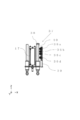
図11に、第二実施形態における重錘昇降装置106の構成を示す。重錘昇降装置106は、昇降シリンダ(図示せず)とフレーム118と重錘昇降爪119と枠体150とを備えている。枠体150は筒形状であり、昇降シリンダは枠体150に囲まれるように配設されている。昇降シリンダは、フレーム118に接続される。重錘昇降爪119は、フレーム118に設けられる。重錘昇降装置106のフレーム118と重錘昇降爪119とは、昇降シリンダによって上下方向に移動することができる(図中のZ軸方向)。重錘13を持ち上げる際、重錘昇降爪119は、重錘13の下面に係合し、係合した状態で上昇する。これにより、重錘昇降装置106は、冷却ライン上の鋳型8上面に載置された重錘13を持ち上げることができる。重錘昇降装置106は、注湯ライン上の鋳型8上面に、冷却ラインにて持ち上げた重錘13を載置することができる。枠体150は重錘昇降装置106と一体になっており、重錘昇降装置106と共に昇降シリンダによって、上下方向に移動する。
図11に示すように、重錘昇降装置106は、減速位置決定装置として2つのレーザーセンサ130を備えている。2つのレーザーセンサ130は枠体150に取り付けられており、水平面(鋳型の上面)に対して垂直にレーザー光を放射するように配置している。レーザーセンサ130は、鋳型8から反射されたレーザー光を受信することにより、レーザーセンサ130から鋳型8までの距離を連続的に測定することが可能である。そして測定した距離を、随時シーケンサ(図示せず)に送信する。
次に、第二実施形態の重錘載置設備107による重錘載置方法の一例を、図面を参照して説明する。予め、ジャケット昇降装置105により、ジャケット12が、注湯ライン上の鋳型8に被せられている。そして、ジャケット12を被っている鋳型8が、重錘昇降装置106の下に位置している。
重錘昇降装置106により、冷却ライン上の鋳型8に載せられた重錘13が持ち上げられ、注湯ライン上の鋳型8に移動される。その後、重錘昇降装置106によって重錘13を下降する。2つのレーザーセンサ130がそれぞれ、鋳型8の上面に向けてレーザー光を垂直に放射し、レーザーセンサ130から鋳型8上面までの距離の計測を開始する(計測工程)。この計測工程では、重錘昇降装置106により重錘13の下降が開始されてから鋳型8の上に載置されるまで連続的に距離を計測しており、その計測結果をシーケンサに送信している。なお、重錘昇降装置106が重錘13を下降しているとき、2つのレーザーセンサ130は枠体150に取り付けられているため、重錘昇降装置106と共に移動する。一方、鋳型8は注湯ライン上に載置されている。そのため、レーザーセンサ130は時間経過と共に鋳型8に近づいていく。
重錘昇降装置106を第一下降速度から第二下降速度への減速を開始するときの、レーザーセンサ130から鋳型8上面までの距離PSが、予め設定されている。重錘昇降装置106による重錘13の下降中に、レーザーセンサ130によって連続的に計測されている距離が距離PSになったとき、重錘昇降装置106の減速位置を決定し、減速を開始する(減速位置決定工程)。なお、重錘昇降装置106による重錘13の下降工程は、下降を開始してから減速位置まで、第一下降速度で下降する工程(第一重錘下降工程)と、減速位置から鋳型8に載置されるまで、第二下降速度で下降する工程(第二重錘下降工程)とに分けられる。第二実施形態における距離PSは、第一下降速度から第二下降速度への減速距離等を考慮して、任意に設定される。
2つのレーザーセンサ130が連続的に計測している距離の内、小さい値の方が距離PSになったとき、重錘昇降装置106の減速を開始するように設定する。片方のレーザーセンサ130から放射されるレーザー光が、鋳型8上面における湯口に当たっている場合を考慮するためである。
定盤台車上に鋳型8が載置されていない場合(ジャケット12のみが載置されている場合)、レーザーセンサ130から放射されるレーザー光は定盤台車に当たる。この場合、重錘13の下降が開始するときのレーザーセンサ130による計測距離は、定盤台車上に鋳型8が載置されている場合と比較して、著しく長くなる。この場合、シーケンサは、定盤台車上にジャケット12のみが載置されていると判断する。そして重錘13の減速位置を、ジャケット12の鍔部12aの上面から、第一下降速度から第二下降速度まで減速するために必要な距離だけ上の位置とする。
重錘13を鋳型8の上(若しくはジャケット12上)に載せた後、重錘昇降装置106は一定距離下がって停止する。そして、鋳型8や重錘13に接触しないように、重錘昇降装置106は上昇する。その後、工程を繰り返すために、重錘昇降装置106は冷却ラインの上に移動する。
本実施形態によれば、第一実施形態と異なり、減速位置決定装置が2つのレーザーセンサ130のみであり、減速位置検知装置を有さない。そのため、簡便な設備構成とすることが可能となる。
実施形態では、重錘昇降装置によって重錘を減速する回数を一回としているが、二回以上に減速回数を分割し、段階的に重錘を減速させてもよい。これにより、重錘昇降装置の機械的負荷を抑えることができる。例えば、第一実施形態において鋳型8Lに重錘13を載置する場合、第二近接スイッチ36a、36cがそれぞれ第二検出体38を検出するとき、重錘昇降装置6が減速するように設定してもよい。
1…抜枠造型ライン、5,105…ジャケット昇降装置、6,106…重錘昇降装置、7,107…重錘載置設備、8…鋳型、12…ジャケット、12a…鍔部、13…重錘、30…減速位置決定装置、31…棒部材、32…第一検出体、33a,33b,33c…第一近接スイッチ、36a,36b,36c,36d…第二近接スイッチ、37…減速位置検知装置、38…第二検出体、106…重錘昇降装置、130…レーザーセンサ(光計測手段)。
Claims (9)
- 抜枠造型ライン上の鋳型に重錘を載置する重錘載置設備であって、
前記重錘を下降させて前記鋳型の上に載置させる重錘昇降装置と、
前記重錘昇降装置における前記重錘の下降方向の減速位置を決定する減速位置決定装置と、を具備しており、
前記重錘昇降装置における前記重錘の下降速度は、下降を開始してから前記減速位置に到達するまでの第一下降速度と、前記減速位置から前記鋳型の上に載置されるまでの第二下降速度と、を含み、
前記第二下降速度は、前記第一下降速度よりも低速である、重錘載置設備。 - 前記重錘昇降装置の上流に配置され、ジャケットを前記鋳型の側面に被せるジャケット昇降装置を更に具備しており、
前記減速位置決定装置は、前記ジャケット昇降装置に配設される、請求項1に記載の重錘載置設備。 - 前記減速位置決定装置は、前記重錘昇降装置に配設される、光により前記鋳型の上面までの距離を計測する光計測手段を具備しており、
前記光計測手段は、該光計測手段から放射された光が、前記鋳型の上面に垂直に当たるように配設されている、請求項1に記載の重錘載置設備。 - 前記減速位置決定装置は、
前記ジャケット昇降装置に対して相対的に昇降可能である第一検出体と、
前記ジャケット昇降装置と共に昇降し、前記第一検出体を検出する第一近接スイッチと、を具備しており、
前記第一近接スイッチは、異なる前記鋳型の高さに対応する複数の近接スイッチを備える、請求項2に記載の重錘載置設備。 - 前記重錘昇降装置は、前記減速位置を検知する減速位置検知装置を具備しており、
前記減速位置検知装置は、
前記重錘昇降装置の昇降動作に伴って昇降する第二検出体と、
前記重錘昇降装置に装着され、前記第二検出体を検出する第二近接スイッチと、を具備しており、
前記第二近接スイッチは、異なる前記鋳型の高さに対応する複数の近接スイッチを備える、請求項4に記載の重錘載置設備。 - 前記減速位置決定装置は、前記鋳型の高さ方向に延伸している棒部材を更に具備しており、
前記棒部材の上端には、前記第一検出体が配設されており、
前記棒部材の下端は前記ジャケットに形成されている鍔部に当接可能に配置されている、請求項5に記載の重錘載置設備。 - 前記第一検出体は、前記鋳型の高さ方向に延伸しており、下端が開口している円筒形状である、請求項6に記載の重錘載置設備。
- 請求項2に記載の重錘載置設備を用いて抜枠造型ライン上の鋳型に重錘を載置する方法であって、
前記ジャケット昇降装置により、前記ジャケットを下降させて前記鋳型の側面に被せるジャケット被せ工程と、
前記減速位置決定装置により、前記重錘昇降装置における前記重錘の下降方向の前記減速位置を決定する減速位置決定工程と、
前記重錘昇降装置により、前記減速位置まで前記重錘を前記第一下降速度で下降させる第一重錘下降工程と、
前記重錘昇降装置により、前記減速位置から前記鋳型に前記重錘を載置するまで、前記重錘を前記第二下降速度で下降させる第二重錘下降工程と、
を有する重錘載置方法。 - 請求項3に記載の重錘載置設備を用いて抜枠造型ライン上の鋳型に重錘を載置する方法であって、
前記光計測手段により、該光計測手段から前記鋳型の上面までの距離を計測する計測工程と、
前記計測工程で計測された距離に基づいて、前記重錘昇降装置における前記重錘の下降方向の減速位置を決定する減速位置決定工程と、
前記重錘昇降装置により、前記減速位置まで前記重錘を前記第一下降速度で下降させる第一重錘下降工程と、
前記重錘昇降装置により、前記減速位置から前記鋳型に前記重錘を載置するまで、前記重錘を前記第二下降速度で下降させる第二重錘下降工程と、
を有する重錘載置方法。
Priority Applications (2)
| Application Number | Priority Date | Filing Date | Title |
|---|---|---|---|
| CN201780004428.5A CN108367342B (zh) | 2016-05-07 | 2017-02-09 | 脱箱造型线上的重锤载置设备及重锤载置方法 |
| JP2018516349A JP6673472B2 (ja) | 2016-05-07 | 2017-02-09 | 抜枠造型ラインにおける重錘載置設備及び重錘載置方法 |
Applications Claiming Priority (2)
| Application Number | Priority Date | Filing Date | Title |
|---|---|---|---|
| JP2016-093512 | 2016-05-07 | ||
| JP2016093512 | 2016-05-07 |
Publications (1)
| Publication Number | Publication Date |
|---|---|
| WO2017195421A1 true WO2017195421A1 (ja) | 2017-11-16 |
Family
ID=60268039
Family Applications (1)
| Application Number | Title | Priority Date | Filing Date |
|---|---|---|---|
| PCT/JP2017/004722 Ceased WO2017195421A1 (ja) | 2016-05-07 | 2017-02-09 | 抜枠造型ラインにおける重錘載置設備及び重錘載置方法 |
Country Status (4)
| Country | Link |
|---|---|
| JP (1) | JP6673472B2 (ja) |
| CN (1) | CN108367342B (ja) |
| TW (1) | TW201739542A (ja) |
| WO (1) | WO2017195421A1 (ja) |
Citations (2)
| Publication number | Priority date | Publication date | Assignee | Title |
|---|---|---|---|---|
| JPS58189051U (ja) * | 1982-06-10 | 1983-12-15 | 新東工業株式会社 | 枠合せ装置 |
| JP2010221255A (ja) * | 2009-03-24 | 2010-10-07 | Sintokogio Ltd | 重錘の上・下両面の清掃装置 |
Family Cites Families (4)
| Publication number | Priority date | Publication date | Assignee | Title |
|---|---|---|---|---|
| US3731822A (en) * | 1970-12-24 | 1973-05-08 | Hartman M W Manuf Co Inc | Foundry mold jacket and weight shifter |
| JPS5577972A (en) * | 1978-12-08 | 1980-06-12 | Nippon Kokan Keishiyu Kk | Mold treating method |
| US6216767B1 (en) * | 2000-01-07 | 2001-04-17 | Vulcan Engineering Company, Inc. | Mold handling apparatus |
| JP6064497B2 (ja) * | 2012-10-02 | 2017-01-25 | 新東工業株式会社 | 鋳造用鋳枠 |
-
2017
- 2017-02-09 WO PCT/JP2017/004722 patent/WO2017195421A1/ja not_active Ceased
- 2017-02-09 CN CN201780004428.5A patent/CN108367342B/zh active Active
- 2017-02-09 JP JP2018516349A patent/JP6673472B2/ja active Active
- 2017-02-17 TW TW106105199A patent/TW201739542A/zh unknown
Patent Citations (2)
| Publication number | Priority date | Publication date | Assignee | Title |
|---|---|---|---|---|
| JPS58189051U (ja) * | 1982-06-10 | 1983-12-15 | 新東工業株式会社 | 枠合せ装置 |
| JP2010221255A (ja) * | 2009-03-24 | 2010-10-07 | Sintokogio Ltd | 重錘の上・下両面の清掃装置 |
Also Published As
| Publication number | Publication date |
|---|---|
| JP6673472B2 (ja) | 2020-03-25 |
| CN108367342A (zh) | 2018-08-03 |
| CN108367342B (zh) | 2020-07-24 |
| TW201739542A (zh) | 2017-11-16 |
| JPWO2017195421A1 (ja) | 2019-03-07 |
Similar Documents
| Publication | Publication Date | Title |
|---|---|---|
| CN104858404B (zh) | 铸件毛坯的吊出方法以及装置 | |
| CN104936726B (zh) | 试件采集方法、试件数据管理方法以及试件模型 | |
| CN109967726B (zh) | 脱模方法及脱模装置 | |
| US20250375835A1 (en) | Laser marking apparatus and laser marking method | |
| JP2010506726A (ja) | 鋳物製品の鋳造方法および該鋳造方法に用いられるプレス装置 | |
| KR20180103832A (ko) | 상하 주형의 형 어긋남 검지장치 및 형 어긋남 검지방법 | |
| JP6673472B2 (ja) | 抜枠造型ラインにおける重錘載置設備及び重錘載置方法 | |
| JP5724700B2 (ja) | 無枠造型注湯冷却ラインにおけるジャケット緩め方法及びジャケット緩め装置 | |
| CN112264982A (zh) | 一种板坯自动测长划线装置及划线方法 | |
| JP4437765B2 (ja) | 注湯済枠付砂鋳型の解枠装置 | |
| WO2019163221A1 (ja) | キャビティ部のずれによる不良を防止する方法 | |
| CN104874751A (zh) | 带型箱的上下铸模的合模装置以及合模方法 | |
| CN220011283U (zh) | 一种精准分包堆叠系统 | |
| JP5408797B2 (ja) | 注湯設備 | |
| CN219335938U (zh) | 一种铝合金轮毂重力铸造中的轴圈自动供料加热装置 | |
| CN110666136B (zh) | 一种半自动砂型低压辊道成型系统 | |
| JP2004174567A (ja) | 注湯済枠付砂鋳型の解枠方法及びその装置 | |
| CN110072652B (zh) | 铸造设备的工作方法以及工作装置 | |
| JP2012081485A (ja) | 鋳型造型装置 | |
| JP4430739B2 (ja) | 鋳物製品の鋳造方法および該鋳造方法に用いられるプレス装置 | |
| KR100408674B1 (ko) | 슬라브 크롭 적재장치 | |
| KR20160068038A (ko) | 벤더 세그먼트 승강장치 | |
| CN213033546U (zh) | 一种锻压设备 | |
| JP2011206818A (ja) | 竪型鋳造機用金型 | |
| JP2023128339A (ja) | 鋳型切削用のサンドカッタ |
Legal Events
| Date | Code | Title | Description |
|---|---|---|---|
| ENP | Entry into the national phase |
Ref document number: 2018516349 Country of ref document: JP Kind code of ref document: A |
|
| NENP | Non-entry into the national phase |
Ref country code: DE |
|
| 121 | Ep: the epo has been informed by wipo that ep was designated in this application |
Ref document number: 17795782 Country of ref document: EP Kind code of ref document: A1 |
|
| 122 | Ep: pct application non-entry in european phase |
Ref document number: 17795782 Country of ref document: EP Kind code of ref document: A1 |