WO2017187944A1 - 吸収性物品 - Google Patents
吸収性物品 Download PDFInfo
- Publication number
- WO2017187944A1 WO2017187944A1 PCT/JP2017/014579 JP2017014579W WO2017187944A1 WO 2017187944 A1 WO2017187944 A1 WO 2017187944A1 JP 2017014579 W JP2017014579 W JP 2017014579W WO 2017187944 A1 WO2017187944 A1 WO 2017187944A1
- Authority
- WO
- WIPO (PCT)
- Prior art keywords
- region
- absorber
- sheet
- basis weight
- diaper
- Prior art date
- Legal status (The legal status is an assumption and is not a legal conclusion. Google has not performed a legal analysis and makes no representation as to the accuracy of the status listed.)
- Ceased
Links
Images

Classifications
-
- A—HUMAN NECESSITIES
- A61—MEDICAL OR VETERINARY SCIENCE; HYGIENE
- A61F—FILTERS IMPLANTABLE INTO BLOOD VESSELS; PROSTHESES; DEVICES PROVIDING PATENCY TO, OR PREVENTING COLLAPSING OF, TUBULAR STRUCTURES OF THE BODY, e.g. STENTS; ORTHOPAEDIC, NURSING OR CONTRACEPTIVE DEVICES; FOMENTATION; TREATMENT OR PROTECTION OF EYES OR EARS; BANDAGES, DRESSINGS OR ABSORBENT PADS; FIRST-AID KITS
- A61F13/00—Bandages or dressings; Absorbent pads
- A61F13/15—Absorbent pads, e.g. sanitary towels, swabs or tampons for external or internal application to the body; Supporting or fastening means therefor; Tampon applicators
- A61F13/53—Absorbent pads, e.g. sanitary towels, swabs or tampons for external or internal application to the body; Supporting or fastening means therefor; Tampon applicators characterised by the absorbing medium
- A61F13/531—Absorbent pads, e.g. sanitary towels, swabs or tampons for external or internal application to the body; Supporting or fastening means therefor; Tampon applicators characterised by the absorbing medium having a homogeneous composition through the thickness of the pad
- A61F13/532—Absorbent pads, e.g. sanitary towels, swabs or tampons for external or internal application to the body; Supporting or fastening means therefor; Tampon applicators characterised by the absorbing medium having a homogeneous composition through the thickness of the pad inhomogeneous in the plane of the pad
-
- A—HUMAN NECESSITIES
- A61—MEDICAL OR VETERINARY SCIENCE; HYGIENE
- A61F—FILTERS IMPLANTABLE INTO BLOOD VESSELS; PROSTHESES; DEVICES PROVIDING PATENCY TO, OR PREVENTING COLLAPSING OF, TUBULAR STRUCTURES OF THE BODY, e.g. STENTS; ORTHOPAEDIC, NURSING OR CONTRACEPTIVE DEVICES; FOMENTATION; TREATMENT OR PROTECTION OF EYES OR EARS; BANDAGES, DRESSINGS OR ABSORBENT PADS; FIRST-AID KITS
- A61F13/00—Bandages or dressings; Absorbent pads
- A61F13/15—Absorbent pads, e.g. sanitary towels, swabs or tampons for external or internal application to the body; Supporting or fastening means therefor; Tampon applicators
-
- A—HUMAN NECESSITIES
- A61—MEDICAL OR VETERINARY SCIENCE; HYGIENE
- A61F—FILTERS IMPLANTABLE INTO BLOOD VESSELS; PROSTHESES; DEVICES PROVIDING PATENCY TO, OR PREVENTING COLLAPSING OF, TUBULAR STRUCTURES OF THE BODY, e.g. STENTS; ORTHOPAEDIC, NURSING OR CONTRACEPTIVE DEVICES; FOMENTATION; TREATMENT OR PROTECTION OF EYES OR EARS; BANDAGES, DRESSINGS OR ABSORBENT PADS; FIRST-AID KITS
- A61F13/00—Bandages or dressings; Absorbent pads
- A61F13/15—Absorbent pads, e.g. sanitary towels, swabs or tampons for external or internal application to the body; Supporting or fastening means therefor; Tampon applicators
- A61F13/45—Absorbent pads, e.g. sanitary towels, swabs or tampons for external or internal application to the body; Supporting or fastening means therefor; Tampon applicators characterised by the shape
- A61F13/49—Absorbent pads, e.g. sanitary towels, swabs or tampons for external or internal application to the body; Supporting or fastening means therefor; Tampon applicators characterised by the shape specially adapted to be worn around the waist, e.g. diapers, nappies
-
- A—HUMAN NECESSITIES
- A61—MEDICAL OR VETERINARY SCIENCE; HYGIENE
- A61F—FILTERS IMPLANTABLE INTO BLOOD VESSELS; PROSTHESES; DEVICES PROVIDING PATENCY TO, OR PREVENTING COLLAPSING OF, TUBULAR STRUCTURES OF THE BODY, e.g. STENTS; ORTHOPAEDIC, NURSING OR CONTRACEPTIVE DEVICES; FOMENTATION; TREATMENT OR PROTECTION OF EYES OR EARS; BANDAGES, DRESSINGS OR ABSORBENT PADS; FIRST-AID KITS
- A61F13/00—Bandages or dressings; Absorbent pads
- A61F13/15—Absorbent pads, e.g. sanitary towels, swabs or tampons for external or internal application to the body; Supporting or fastening means therefor; Tampon applicators
- A61F13/53—Absorbent pads, e.g. sanitary towels, swabs or tampons for external or internal application to the body; Supporting or fastening means therefor; Tampon applicators characterised by the absorbing medium
- A61F13/531—Absorbent pads, e.g. sanitary towels, swabs or tampons for external or internal application to the body; Supporting or fastening means therefor; Tampon applicators characterised by the absorbing medium having a homogeneous composition through the thickness of the pad
- A61F13/532—Absorbent pads, e.g. sanitary towels, swabs or tampons for external or internal application to the body; Supporting or fastening means therefor; Tampon applicators characterised by the absorbing medium having a homogeneous composition through the thickness of the pad inhomogeneous in the plane of the pad
- A61F13/533—Absorbent pads, e.g. sanitary towels, swabs or tampons for external or internal application to the body; Supporting or fastening means therefor; Tampon applicators characterised by the absorbing medium having a homogeneous composition through the thickness of the pad inhomogeneous in the plane of the pad having discontinuous areas of compression
-
- A—HUMAN NECESSITIES
- A61—MEDICAL OR VETERINARY SCIENCE; HYGIENE
- A61F—FILTERS IMPLANTABLE INTO BLOOD VESSELS; PROSTHESES; DEVICES PROVIDING PATENCY TO, OR PREVENTING COLLAPSING OF, TUBULAR STRUCTURES OF THE BODY, e.g. STENTS; ORTHOPAEDIC, NURSING OR CONTRACEPTIVE DEVICES; FOMENTATION; TREATMENT OR PROTECTION OF EYES OR EARS; BANDAGES, DRESSINGS OR ABSORBENT PADS; FIRST-AID KITS
- A61F13/00—Bandages or dressings; Absorbent pads
- A61F13/15—Absorbent pads, e.g. sanitary towels, swabs or tampons for external or internal application to the body; Supporting or fastening means therefor; Tampon applicators
- A61F13/53—Absorbent pads, e.g. sanitary towels, swabs or tampons for external or internal application to the body; Supporting or fastening means therefor; Tampon applicators characterised by the absorbing medium
- A61F13/539—Absorbent pads, e.g. sanitary towels, swabs or tampons for external or internal application to the body; Supporting or fastening means therefor; Tampon applicators characterised by the absorbing medium characterised by the connection of the absorbent layers with each other or with the outer layers
Definitions
- the present invention relates to an absorbent article, and more particularly, to a disposable diaper and an absorbent pad.
- Absorbent articles such as disposable diapers (hereinafter, also simply referred to as “diapers”) have been improved in various ways to improve their functions and wearing feeling.
- Absorbent article absorbs most of the body fluid discharged by the absorber.
- the diaper since the diaper covers the abdomen, buttocks and crotch parts, it is affected by various body movements, particularly leg movements such as walking, turning over, and baby's high and low.
- the absorbent body may be twisted, broken, or cracked by various body movements. If it does so, the fitting property to the crotch of a diaper will fall and it will become easy to raise
- the content of the superabsorbent polymer (Super Absorber Polymer, hereinafter referred to as “SAP”) in the absorber is increased in order to increase the absorption retention of the absorber, the flexibility of the absorber itself tends to be lost. Have.
- Super Absorber Polymer Super Absorber Polymer
- the skin contact surface side of the absorber is embossed, which is an oblique grid-like compressed groove extending obliquely with respect to the direction from the front to the back of the diaper.
- embossing the absorbent body it has been possible to improve the fit between the crotch of the diaper following the back-and-forth movement of the leg and the roundness of the buttocks, and suppress the leakage of bodily fluids.
- embossing is formed by rotating and moving an embossing roll having an embossing pattern protruding on the surface on a long absorbent sheet.
- the embossing roll was rotated on a long absorbent sheet or the like and embossed, and then cut into a necessary size by laminating various sheets.
- the top sheet and the absorbent body from the top sheet (top sheet) side disposed on the skin contact surface side of the absorbent body in order to prevent the groove from sagging.
- Compressed grooves that are more difficult to loosen are proposed.
- the compressed groove is formed by rotating the embossing roll on the absorbent body on which the top sheet is laminated.
- an emboss pattern having a component extending in an oblique direction such as an oblique lattice shape
- the compressed groove itself is at a lower position than the uncompressed portion, it does not touch the wearer's skin directly, but the vicinity of the lattice point, that is, the lattice crossing region and / or the periphery thereof is the surface sheet and The absorbent body is pulled and fixed in a tight state. For this reason, the powdery SAP in the absorbent body sometimes hits the top sheet. If it does so, the cross
- This crossing region of the lattice touches the wearer's skin, which gives the wearer a firm feel and a stiff feel, which is not preferable.
- the diaper is in contact with delicate skin parts such as the crotch, so that a soft touch is required. If the crossing part of the lattice is hard, the touch of the skin is not preferable.
- the present invention has been made in view of such problems, and the object of the present invention is to prevent the intersecting region and / or the periphery thereof from becoming hard even if a lattice-like emboss pattern is formed on the absorber.
- An object of the present invention is to provide an absorbent article that is easily broken and has improved wearer's feeling (softness).
- the absorbent article of the present invention includes a liquid-permeable top sheet, a liquid-impermeable back sheet, and an absorbent body disposed between the top sheet and the back sheet.
- An absorbent article comprising a plurality of recesses formed by compressing an absorbent body, and a plurality of compressed rows intersecting each other, wherein the compressed region has an intersecting region and / or around the intersecting region. Is characterized in that a low basis weight part is provided.
- the crossing region and / or the periphery thereof are not easily stiffened and are not easily broken. It is possible to provide an absorbent article with improved feeling of use (softness, not rugged).
- FIG. 3 is a cross-sectional view of the diaper shown in FIG. 2 cut along line III-III. It is the stereographic projection figure which expand
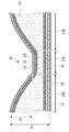
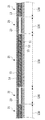
- FIG. 7 is a sectional view taken along line VIII-VIII in FIG. 6.
- FIG. 7 is a cross-sectional view taken along line IX-IX in FIG. 6.
- FIG. 7 is a cross-sectional view taken along line XX in FIG. 6.
- FIG. 7 is a cross-sectional view taken along line XX in FIG. 6 according to a modification of the present invention.
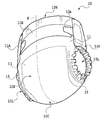
- FIG. 1 The perspective view seen from the front side in the deployment type disposable diaper (what is called a tape type disposable diaper) concerning Embodiment 1 of the present invention is shown in FIG.
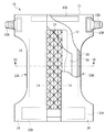
- FIG. 2 shows a plan view of the diaper shown in FIG. 1 developed from the skin contact surface side.
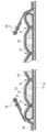
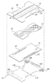
- FIG. 3 is a sectional view taken along line III-III in FIG. Furthermore, the division
- the unfoldable disposable diaper (hereinafter sometimes simply referred to as a diaper) 10 in the present embodiment includes a front body region 10F, a back body region 10R, and a crotch region 10C that connects the front body region 10F and the back body region 10R. And have. Moreover, the waist periphery opening part 10W which surrounds a wearer's waist part with the front body area
- the front body region 10F is positioned on the wearer's ventral side, and the back body region 10R is positioned on the wearer's back side.
- the crotch region 10 ⁇ / b> C covers the wearer's crotch, and the leg of the wearer is passed through the pair of left and right leg openings 10 ⁇ / b> L. Therefore, the leg periphery opening 10L is located at any position around the thigh from the base of the wearer's legs.
- the virtual line P extends through the crotch portion from the abdominal side to the back side at the center of the diaper 10.
- the virtual line P extends along the surface of the diaper 10 in the vertical direction and passes through the crotch portion to The side also extends in the vertical direction.
- the vertical direction is a direction along the center axis of the body from the wearer's head to the crotch, and the virtual line P extends along the center axis of the body.
- the left and right end edges of the back body region 10R of the cover sheet 11 positioned outside the diaper 10 are overlapped with the left and right end edges of the front body region 10F when worn, and are connected to form a leg opening 10L.
- a pair of left and right fastening tapes 10A to be obtained are joined.
- the fastening tape 10A is bonded to the front patch sheet 10B bonded on the cover sheet 11 in the front body region 10F so as to be repeatedly peelable.
- an elastic sheet 10D that extends along the width direction of the cover sheet 11 and gives an appropriate wearing feeling around the waist to the wearer is joined to the upper end portion of the rear body region 10R of the cover sheet 11. Has been.
- the diaper 10 includes a cover sheet 11, a liquid-impermeable back sheet (back sheet) 12 in order from the outside, as viewed from the skin side of the wearer,
- An absorbent body 13 (hereinafter also simply referred to as an absorbent body 13) wrapped with a core wrap (tissue) 15 that is a thin hydrophilic sheet and a top sheet (surface sheet) 14 that touches the wearer's skin are sequentially stacked. It is joined.
- the liquid-impermeable back sheet 12 is joined to the cover sheet 11, and the previous absorbent body 13 is disposed between the back sheet 12 and the liquid-permeable top sheet 14.
- the top sheet 14 is joined to the back sheet 12.
- thread rubber 16 for forming leg gathers is joined in an extended state.
- a pair of liquid-impermeable (or hydrophobic) side sheets 18 forming a three-dimensional gather is provided.
- the pair of side sheets 18 are formed in the same shape as the pair of cutout portions 11A of the cover sheet 11 at the outer end edges, and stand up along the left and right side edges of the absorbent body 13 when worn, and the wearer excretes. This is a member for preventing side leakage of urine.
- the rubber thread 19 as a three-dimensional gather elastic material is folded and gripped on its inner edge toward the absorber 13 side. Furthermore, it rises toward the wearer's skin contact direction.
- the three-dimensional gather can employ a known configuration used in conventional disposable diapers. For example, it can be formed by sandwiching and fixing a stretched three-dimensional gather elastic material between the layers of the water repellent sheet. As shown in FIG. 2, the side sheet 18 is drawn in the longitudinal direction by the expansion and contraction of the rubber thread 19. And as FIG. 3 shows, it becomes a three-dimensional gather where the inner edge part stood
- the absorber 13 becomes long along the virtual line P, and the longitudinal direction is parallel to the virtual line P.
- a direction orthogonal to the virtual line P is defined as a width direction.
- the ratio of the longitudinal direction of the diaper 10 and the width direction is not limited to this embodiment. This ratio is appropriately changed according to the wearer's body shape.
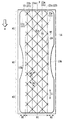
- FIG. 5 is a partial top view of the portion where the absorber 13 and the top sheet 14 are located as viewed from the top sheet 14 side.
- the absorber 13 of this embodiment located under the top sheet 14 is mainly composed of pulp and SAP.
- the absorbent body 13 has an elongated shape so as to cover the front body, the crotch, and the back body. And it is divided into the front body part M1, the crotch part M2, and the back body part M3.
- a pair of notches 13A having an arc shape is formed in accordance with a pair of left and right leg openings 10L surrounding the thick crotch portions of both legs.
- the cutout portion 13 ⁇ / b> A may not be formed according to the size of the absorber 13.
- the absorbent body 13 of the present embodiment is provided with a notch 13A and has an hourglass shape in which the width of the central portion is narrower than the front and rear ends, but the shape of the absorbent body of the present invention is the same. Not exclusively.
- the front body part and the back body part are the front and back (up and down) direction, and the direction orthogonal to it is the left and right direction, for example, the corners of the front and back (up and down) ends are rounded off, the ellipse extending in the front and back (up and down)
- Various shapes are included, such as a rectangular shape, a circular shape, and a rectangular shape having the same length in the front and rear (up and down) left and right.
- the absorbent body 13 is wrapped with a core wrap 15 that is a hydrophilic thin sheet in which end portions are bonded to each other by gluing.
- the absorbent body 13 wrapped with the core wrap 15 is disposed between the back sheet 12 and the top sheet 14.
- the top sheet 14 is joined to the back sheet 12 via the absorbent body 13 wrapped with the core wrap 15.
- the absorber 13 wrapped with the core wrap 15 is used, the absorber in this invention does not need to be wrapped with the core wrap.
- the diaper 10 has the compression part formation area
- the compression portion forming region N1 is composed of a plurality of concave portions 21 that are compressed and continuously formed, and a plurality of compression rows 22 in which the plurality of concave portions 21 are arranged in an oblique lattice pattern are arranged and extended. ing.
- the plurality of compressed columns 22 intersect each other.
- an uncompressed main absorption region 26 is mainly provided in a region where the compression row 22 is not formed in the compression portion formation region. As shown in FIG.
- the emboss pattern is not formed on both ends of the absorber 13. Therefore, the absorber 13 is one in which the compression part non-formation area (emboss pattern non-formation area) N2 is located on both sides of the compression part formation area (emboss pattern formation area) N1. This is to prevent body fluid from leaking from the leg opening 10L through the emboss pattern.
- the emboss pattern is formed up to the upper end portion of the front body portion M1 and the lower end portion of the rear body portion M3.
- the embossed pattern allows an aspect in which the upper end portion of the front body portion M1 and the lower end portion of the rear body portion M3 of the absorbent body 13 are not formed, and an aspect in which the embossed pattern is formed up to the left and right ends of the absorbent body 13. It is.
- the concave portion 21 in the present embodiment is inclined with respect to an imaginary line P along the center axis of the wearer's body when the diaper is worn.
- the recess 21 has a right angled recess 21a that is inclined in the right direction in the drawing, which is the first direction, with respect to the virtual line P, and a left in the drawing, which is in the second direction, with the predetermined angle ⁇ .
- a leftward-facing recess 21b inclined in the direction.
- the concave portions 21 inclined in the same direction are arranged so that the diagonal lines of one lattice of the lattice form a row with a length L1, and form an emboss pattern in a lattice shape extending obliquely.
- the predetermined angle ⁇ and the predetermined angle ⁇ are the same value, but they may be different values.
- the plurality of recesses 21 are formed by compressing the top sheet 14, the core wrap 15, and the absorber 13 together on the top sheet 14 side.
- the absorbent body 13 and the top sheet 14 may be embossed together as in this embodiment, or the top sheet 14 is attached to the absorbent body 13 after embossing later. Also good.
- a row in which a plurality of rightward concave portions 21a are arranged is referred to as a first compression row 22a
- a row in which a plurality of leftward concave portions 21b are arranged is referred to as a second compression row 22b.
- These compression rows 22 are linearly inclined with respect to the virtual line P at the same angle as the inclination angle of the recess 21.
- the first compression rows 22a extend in parallel with each other with an interval S1.
- column 22b is mutually extended in parallel with the space
- the intersecting region 25 is formed by the first compressed row 22a and the second compressed row 22b intersecting each other.
- the intervals S1 and S2 are the same value, but they may be different values.
- the low basic weight part 23 is provided in the intersection area
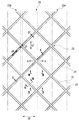
- FIG. 6 is an enlarged schematic view of a part of the compressed string in the portion indicated by the arrow VI in FIG. 5 and 6 are drawn with the side sheet 18 omitted for convenience.
- the low basis weight part 23 is represented by a two-dot chain line in FIGS. 5 and 6.
- the low basic weight part 23 is formed by adjusting the basic weight of pulp and SAP constituting the absorbent body 13 and lowering the basic weight when the absorbent body 13 is manufactured.
- an oblique lattice-shaped intersection region 25 of the first compression row 22a and the second compression row 22b is formed on the surface of the absorber 13 of the present embodiment. Furthermore, a plurality of low basis weight portions 23 that are regions including a plurality of intersecting regions 25 extending in the extending direction (longitudinal direction) of the absorber 13 are formed on the surface of the absorber 13.
- the low basis weight portions 23 of the present embodiment are arranged in parallel with an interval L2.
- the low basis weight portion 23 of the present invention is not limited to those arranged in parallel if provided in the intersection area 25 and / or its periphery, that is, the area having a basis weight lower than the surrounding area is the intersection area 25 and As long as it is formed so as to at least partially overlap the periphery thereof, various modes can be adopted.
- the low basis weight part 23 is arrange
- the density of the pressing part is low. become. Therefore, the density of the absorbent body 13 in the low basis weight portion 23 in the intersecting region 25 is lower than the density of the absorbent body 13 in the region where the compression row 22 other than the low basic weight portion 23 is formed.
- the low basic weight part 23 is comprised including the vertical direction low basic weight part 23c formed in parallel with respect to the virtual line P, as shown in FIG.
- a row in which a plurality of vertical low basis weight portions 23c are arranged is referred to as a low basis weight row 24c.
- the low basis weight portion 23 has a vertical stripe shape.
- the width of the vertical stripe in the embodiment may be widened or narrowed. Further, for example, various shapes such as a quadrangle, a circle, an ellipse, and a triangle can be adopted.
- the low basic weight part 23 which concerns on this embodiment is formed by the following processes (1) to (6), for example.
- the absorbent mat (representing an absorbent main body that does not include a core wrap in the description of this process) is formed by mixing pulp and powdery SAP and spraying them onto the filters of two forming drums, for example.
- the absorbent mat having the depressions is wrapped with the core wrap 15, and the core wrap 15 and the absorbent mat are bonded together by hot melt or the like, thereby creating the absorbent body 13.
- the top sheet 14 is laminated on the cut absorber 13.
- the top sheet 14 and the absorber 13 are combined and compressed with an embossing roll.
- the core wrap 15 is adhered to the bottom portion of the recess by suction conveyance to the absorber 13 in the step (3), embossing in the step (6), and the low basis weight portion 23 is shown in FIG. It becomes a shape like this.
- the low basis weight portion 23 is not only provided by two forming drums as in the present embodiment, but may be provided at the time of embossing in the present invention.
- the low basic weight part 23 is provided in the intersection area
- the tension increases as the distance of the compressed portion approaches, so it is preferable to reduce the basis weight according to the distance from the viewpoint of making the top sheet 14 difficult to break. Therefore, it is preferable that the basis weight of the low basis weight portion 23 is formed so as to decrease toward the center of the intersecting region 25 (for example, in a mortar shape).
- the crossing region 25 does not become hard, it becomes possible to make the top sheet 14 difficult to break, and the diaper 10 can be easily bent in either direction with the lattice side extending direction of the recess 21 as an axis. It becomes possible to improve the property.
- the recesses 21 of the embossed pattern in the diagonal lattice shape are formed by pressing an embossing roll having a mold formed on the surface in accordance with the recesses 21 while rotating.
- the embossing roll rotates and advances in the direction of arrow W (direction from the front body part M1 toward the back body part M3), the recesses line up in a direction orthogonal to the advancing direction W of the embossing roll. All 21 portions are pressed simultaneously.
- the size of the embossing roll is determined so that the circumference of the embossing roll corresponds to the length of the absorbent body 13 in the longitudinal direction, but is not limited thereto.
- the advancing direction W of an embossing roll is parallel to the direction used as the previous virtual line P when the diaper 10 is completed.
- the top sheet 14 is laminated
- the advancing direction W of an embossing roll and the extending direction of the low basic weight part 23 are parallel, it becomes easy to match
- the right-side concave portion 21a is inclined in the right direction with respect to the traveling direction W, and the left-side concave portion 21b is inclined in the left direction. For this reason, as the embossing roll advances in the traveling direction W, the distance between the right-facing recess 21a and the left-facing recess 21b that are adjacent to the intersecting region 25 decreases.
- the top sheet 14 is pulled so as to be pulled into the recess 21. Since the adjacent right-facing recess 21a and left-facing recess 21b are formed by pressing at the same time, the top sheet 14 positioned therebetween is pulled from the left and right. That is, in FIG. 6, the pulling force indicated by the arrow A is applied to the left and right simultaneously, and the top sheet 14 is pulled. As the distance between the adjacent right-facing recess 21a and left-facing recess 21b becomes shorter, the margin for the pull of the pull-in force A of the top sheet 14 decreases, so the top sheet 14 becomes tightly stretched. For this reason, the SAP in the absorbent body 13 hits the top sheet 14, and the surface of the top sheet 14 becomes rough. This is not preferable because it is irritating to the wearer's skin.
- the top sheet 14 is further stretched, and therefore the top sheet 14 may be torn.
- the embossing roll is simply pressed shallowly to form the recess 21, the adhesive effect between the top sheet 14 and the absorbent body 13 is weakened, and the top sheet 14 is easily peeled off from the absorbent body 13. It becomes impossible to form the embossed pattern.
- the concave portion 21 of the present embodiment has a concave portion without strongly stretching the top sheet 14 because the distance between the adjacent rightward concave portion 21a and the leftward concave portion 21b becomes shorter and at the same time enters the intersecting region 25 with a low basis weight. 21 is formed.
- the absorbent body 13 to be pressed down is small, the top sheet 14 is not easily broken, and the corner portion formed in the intersecting region 25 is not hardened and feels good, and the surface of the top sheet 14 is smooth. It becomes. Furthermore, it is possible to prevent the top sheet 14 from being peeled from the absorbent body 13 while maintaining the softness of the top sheet 14 and the absorbent body 13.
- the intersecting region 25 having a low basis weight is intermittently formed in the extending direction of the compression row 22.
- the diaper 10 of this embodiment can improve the easiness of bending in the intersection area
- FIG. 7 is a cross-sectional shape taken along line VII-VII in FIG. 6,
- FIG. 8 is a cross-sectional shape taken along line VIII-VIII in FIG. 6,
- FIG. 9 is a cross-sectional shape taken along line IX-IX in FIG. It is the schematic diagram which expanded each cross-sectional shape by X-ray
- the part represented by reference sign 13D is a high basis weight / compressed portion of the absorbent body 13 that has a high basis weight and is being compressed.
- symbol 13E is a high basic weight and the unsqueezed part which is a high basic weight among the absorbers 13, and is not compressed. That is, the high basis weight / compressed portion 13 ⁇ / b> D represents the recess 21 other than the intersecting region 25, and the high basis weight / non-compressed portion 13 ⁇ / b> E represents the absorbent body 13 in the main absorbent region 26.
- the absorbent body 13 is mainly made of SAP and pulp, and the density mainly involves the pulp fiber density. Accordingly, the high basis weight / compressed portion 13D is in a state where the pulp is compressed and there are few gaps between the pulps, while the high basis weight / non-pressed portion 13E has a gap between pulps higher than that of the high basis weight / pressed portion 13D. There are many states.
- the concave portion 21 is formed in a film shape by compressing and joining together the top sheet 14 which is a synthetic fiber and the absorbent body 13 of the pulp as a main component, the bottom surface of the concave portion 21 until the body fluid is absorbed. Facilitates diffusion of body fluid in the direction in which the compression row 22 extends.
- the absorber 13 is bonded to the top sheet 14 and the core wrap 15 in the low basis weight portion 23.
- FIG. 9 the cross-sectional shape of the intersection region 25 is shown.
- symbol 13F is the low basic weight and the non-compressed part which are the low basic weights among the absorbers 13, and are not compressed.
- symbol 13G is the low basic weight and pressing part which is the low basic weight among the absorbers 13, and is squeezed.
- the low basis weight / non-pressed portion 13 ⁇ / b> F represents a portion of the low basis weight portion 23 that is not pressed
- the low basis weight / pressed portion 13 ⁇ / b> G represents a portion of the low basis weight portion 23 that is compressed.
- the low basis weight portion 23 (low basis weight / pressed portion 13 ⁇ / b> G) in the intersecting region 25 is pushed down to the same thickness as the concave portion 21, but has a low basis weight. It is possible to maintain a lower density than the recesses 21 other than 25 (high basis weight / pressed portion 13D). That is, as shown in FIG.
- the absorbent body 13 (low basis weight / pressed portion 13 ⁇ / b> G) in the intersecting region 25 is compressed more than the low basis weight / non-pressed portion 13 ⁇ / b> F shown in FIG. 8, but the intersecting region 25.
- the density is lower than the recesses 21 (high basis weight / pressed part 13D) other than the above. As described above, it is possible to maintain low density and reduce the thickness in the intersecting region 25 of the absorber 13, so that softness can be maintained in the intersecting region 25.
- the density of the absorbent body 13 (low basis weight / pressed part 13G) in the intersecting region 25 is the absorbent body 13 (high basis weight / compressed part 13D) in the region where the compression row 22 other than the intersected region 25 is formed. ) Is lower than the density.
- the density of the absorber 13 of the low basic weight part 23 will be equal to the density of the absorber 13 of the crossing area
- the thickness of the absorber 13 at the bottom where the compressed row 22 including the intersecting region 25 is formed is substantially constant, but the present invention is not limited to this.
- a concave portion deeper than the concave portion 21 of the compression row 22 may be provided in the intersecting region 25 where the low basis weight portion 23 is provided.
- the density of the absorber 13 of the low basis weight portion 23 in the intersecting region 25 can be equal to or higher than the density of the absorber 13 of the compressed row 22 other than the low basis weight portion 23.
- the density of the low basis weight / compressed portion 13 ⁇ / b> G of the absorbent body 13 in the compressed row 22 that is the region including the intersecting region 25 is the compressed row that is the region not including the intersecting region 25. It is lower than the density of the high basis weight / compressed portion 13D of the absorbent body in the region where 22 concave portions are formed.
- the embossed pattern of the present embodiment has a lattice shape in which a plurality of recessed portions 21 extending continuously are arranged, and the length of the diagonal line L1 of one lattice is 42 mm (4.2 cm).
- the recessed part 21 is arrange
- the first compression row 22a extends in parallel at the interval S1
- the second compression row 22b extends in parallel at the interval S2. ing.
- the first compressed row 22a and the second compressed row 22b form an emboss pattern having an oblique lattice shape.
- the lengths S1 and S2 of one side of the grating are equal and 29.7 mm.
- the interval between the lattices is preferably 13.0 mm or more and 54.0 mm or less.
- the depth of the recess 21 in the absorbent body 13 is D1, the thickness of the absorbent body 13 and the top sheet 14 before embossing, that is, the maximum composed of the absorbent body 13 and the top sheet 14 in the main absorbent region 26.
- the thickness of the diaper 10 of the recess 21 is D3
- the thickness of the absorber 13 in the recess 21 is D4.
- the thickness D2 is 8.0 mm, preferably 5.0 mm to 20.0 mm.
- thickness D3 is 1.0 mm.
- the thickness D4 (see FIG. 7) of the absorber 13 in the recess 21 is preferably 0.2 mm to 0.6 mm.
- the depth D1 of the recess 21 is about 42.5% to 97.5% of the thickness D2.
- the recessed part 21 in this embodiment forms the recessed part 21 by compressing the absorber 13 toward the back sheet 12 in the press by the embossing roll.
- the density of the absorber 13 (low basis weight / pressed portion 13G) in the intersecting region 25 in the embossed pattern of the present embodiment is 0.8 g / cm 3 , and is 0.5 g / cm 3 to 1.2 g / cm 3. preferable. Further, the density of the absorbent body 13 (high basis weight / pressed portion 13D) of the concave portion 21 other than the intersecting region 25 according to the present embodiment is 1.38 g / cm 3 , and 0.8 g / cm 3 to 1.9 g. / Cm 3 is preferred. Furthermore, the density of the absorbent body 13 other than the recess 21 according to this embodiment (high basis weight and non-compressed portion 13E) is 0.05g / cm 3, 0.03g / cm 3 ⁇ 0.07g / cm 3 Is preferred.
- the rigidity of the intersecting region 25 can be softened. Therefore, even if a lattice-shaped emboss pattern is formed on the absorbent body 13, the intersecting region 25 does not become hard and is easily broken, and the wearer's feeling of use (softness) can be improved.
- the groove can be maintained even when weight is applied, and the soft touch can be maintained on the skin contact surface of the crotch part of the diaper. Can do. Therefore, the slanted grid-like embossed pattern can suppress deformation such as diaper swaying with respect to various movements of the legs, and the touch can be made soft to suppress irritation to the skin as much as possible.
- the thin and medium-density intersection region 25 is Q1
- the region sandwiching the thin and high-density compression row 22 in the width direction is Q2
- the thick and low-density main absorption region 26 is Q3.
- a region along the extending direction of the thin and high-density compression row 22 is defined as Q4.
- the order of the rigidity (difficulty in bending, bending strength) of the diaper 10 having such a density distribution is such that a region Q1 ⁇ region Q3 ⁇ region Q2 ⁇ region Q4 from a soft (and easy to bend) portion to a hard (and hardly bendable) portion. , Can be ordered.
- the embossing is performed using an embossing roll.
- the embossing is not limited to this method, and embossing is performed in units of diaper size using a plate-like embossing plate that matches the size of the diaper. What you push may be used.
- the top sheet 14 may be disposed directly on the absorber 13.
- a liquid diffusion sheet for improving liquid diffusibility may be provided between the top sheet 14 and the hydrophilic sheet. This sheet makes it easier for body fluid to diffuse.
- the hydrophilic sheet may be attached so as to enclose the absorbent body 13, or may be simply disposed so as to overlap the front and back without wrapping the end of the absorbent body 13.
- column 22 is formed by the recessed part 21 which is a continuous groove
- the shape of the recessed part 21 is not restricted to the shape shown to this embodiment, Various shapes, such as a square, a circle, an ellipse, and a triangle, can be taken.
- the disposable diaper 10 according to the above embodiment is applicable to both adults and children.
- the unfolded diaper 10 (so-called tape-type diaper) has been described as an example.
- the present invention is also applicable to a pants-type diaper.
- the absorbent article of the present invention is not limited to diapers, but can be applied to other general various absorbent articles such as an absorbent pad and a urine leak pad.
- the present invention can be applied to an absorbent pad or the like from the structure of the absorbent body 13 and the top sheet 14, and has the same effects as a diaper.
- the absorber 13 only one side of the absorber 13 is embossed, but this is not restrictive, and double-sided embossing may be employed. That is, the recesses 21 are formed on both the front and back surfaces of the absorbent body 13 by embossing from both the top sheet 14 side and the back sheet 12 side. Thereby, in order not to concentrate a pressure only on one surface among the front and back of the absorber 13, the compression row
- the recess 21 is formed continuously.
- the recess 21 may be formed discontinuously.
- region 25 also changes.
- 11 is a cross-sectional view taken along line XX of FIG. 6 according to a modification of the present invention.
- those having the same function are denoted by the same reference numerals as those in the above embodiment, and the description thereof is omitted.
- the concave portion 21 is not formed in a portion corresponding to the intersecting region 25 where the compression row 22 intersects. Then, as shown in FIG. 11, the low basis weight portion 23 (low basis weight / pressed portion 13G) in the intersecting region 25 is not compressed, and is slightly compressed along with the pressing of the concave portion 21 around the intersecting region 25, and is viewed in cross section. In FIG. 6, it is formed so as to rise slightly to the skin contact side (see FIG. 6 of the above embodiment for comparison). With this configuration, the density of the absorber 13 in the intersecting region 25 is lower than the density of the recesses 21, so that the same effect as in the above embodiment can be obtained.
Landscapes
- Health & Medical Sciences (AREA)
- Epidemiology (AREA)
- Engineering & Computer Science (AREA)
- Biomedical Technology (AREA)
- Heart & Thoracic Surgery (AREA)
- Vascular Medicine (AREA)
- Life Sciences & Earth Sciences (AREA)
- Animal Behavior & Ethology (AREA)
- General Health & Medical Sciences (AREA)
- Public Health (AREA)
- Veterinary Medicine (AREA)
- Absorbent Articles And Supports Therefor (AREA)
Abstract
本発明は、液透過性の表面シート(14)と、液不透過性の裏面シート(12)と、表面シート(14)と裏面シート(12)との間に配された吸収体(13)とを備える吸収性物品であって、吸収体(13)を圧縮して形成された複数の凹部(21)で構成され、かつ互いに交差する圧縮列(22)が複数配列し、圧縮列(22)の交差領域(25)および/または該交差領域(25)の周辺には、低坪量部(23)が設けられることを特徴とするものである。
Description
本発明は、吸収性物品に関し、特に、使い捨ておむつや吸収パッドに関する。
使い捨ておむつ(以下、単に「おむつ」とも言う)等の吸収性物品においては、さまざまな改良が行われ、その機能や着用感の向上が図られている。
吸収性物品は、吸収体によって排出された体液のほとんどを吸収する。ここで、おむつは、腹、尻および股部分を覆うものであるので、歩行や寝返り、赤ちゃんのハイハイなどのさまざまな体、特に脚の動きの影響を受ける。特に、吸収体は、体のさまざまな動きによって、よれたり、折れたり、割れたりする場合がある。そうすると、おむつの股間へのフィット性が低下し、液漏れを起こしやすくなる。さらに、吸収体の吸収保持性を高めるために、吸収体における高吸水性樹脂(Super Absorbent Polymer、以下「SAP」とも言う)の含有率を高めると、吸収体自体のしなやかさが失われる傾向を持つ。
そこで、特許文献1に見られるように、吸収体の肌当接面側に、おむつの前身頃から後身頃にわたる方向に対して傾斜して伸びる斜め格子状の圧縮溝であるエンボス加工を施したものがある。このように、吸収体にエンボス加工を施すことにより、脚の前後運動や臀部の丸みに追従しておむつの股間へのフィット性を高め、体液の漏れを抑制してきた。
また、このようなエンボス加工は、表面にエンボスパターンが突起するエンボスロールを、長尺の吸収体シート上で回転移動させることで形成される。おむつ製造時は、長尺の吸収体シート等上でエンボスロールを回転させてエンボス加工した後、各種シートを積層する等して必要な大きさに切断していた。
ところで、着用者の体重による圧力が加わっても、溝がへたらないようにするために、吸収体の肌当接面側に配置される表面シート(トップシート)側から、表面シートと吸収体とを共に圧縮し、よりへたりにくい圧縮溝が提案されている。この場合も上述したように、エンボスロールを表面シートが積層された吸収体上に回転させることにより圧縮溝を形成する。このようにして圧縮溝を形成する際、エンボスロールの回転によって、吸収体よりも上層に位置する表面シート等が、溝に向かって食いこんでいき、表面シート等は強く張った状態となりやすい。特に、斜め格子状など、斜め方向に伸びる成分を有するエンボスパターンは、格子点付近など、同時に圧縮される地点間の距離が短くなる(間隔が狭くなる)部分がある。同時に圧縮される地点間の距離が短いと、隣接する圧縮地点双方から表面シートを引っ張る力が強く働き、表面シートが強く張った状態となりやすい。そうすると、吸収体内の粉末状のSAPが表面シートに当たることにより、エンボス加工時に交差領域の表面シートが破れやすくなる。
また、圧縮溝自体は、圧縮されていない箇所に比べて低い位置にあるため、着用者の肌に直接触れないが、格子点近傍、すなわち格子の交差領域および/またはその周辺は、表面シートおよび吸収体が引っ張られて強く張った状態で固定されている。このため、吸収体内の粉末状のSAPが表面シートに当たる場合があった。そうすると、表面シートの肌当接面における格子の交差領域および/またはその周辺は、高吸収性樹脂のごつごつ感が手触りとして伝わってしまうなど、他の部分に比べて硬いものとなってしまう。
この格子の交差領域が着用者の肌に触れることにより、着用者に肌触りの硬さやごわごわした感触を与えてしまい、好ましくなかった。特におむつは、股間などのデリケートな肌部分に接するため、柔らかな肌触りが求められ、格子の交差部分が硬いと、肌に当たる感触は好ましくなかった。
本発明は、このような問題に鑑みてなされたもので、その目的とするところは、吸収体に格子状のエンボスパターンが形成されていても、交差領域および/またはその周辺が固くならずに折れやすくなり、着用者の使用感(柔らかさ)を向上させた吸収性物品を提供することにある。
このような目的を達成するために、本発明の吸収性物品は、液透過性の表面シートと、液不透過性の裏面シートと、表面シートと裏面シートとの間に配された吸収体とを備える吸収性物品であって、吸収体を圧縮して形成された複数の凹部で構成され、かつ互いに交差する圧縮列が複数配列し、圧縮列の交差領域および/または該交差領域の周辺には、低坪量部が設けられることを特徴とする。
以上説明したように、本発明によれば、吸収体に格子状のエンボスパターンが形成されていても、交差領域および/またはその周辺が固くならずに折れやすくなり、破れにくくして、着用者の使用感(柔らかさ、ごつごつしない)を向上させた吸収性物品を提供することができる。
以下、図面を参照しながら本発明の実施形態について詳細に説明する。しかしながら、本発明はこれらの実施形態のみに限らず、本発明の概念に帰属する他の吸収性物品も包含するものである。
[実施形態1]
本発明の実施形態1に係る展開型使い捨ておむつ(いわゆるテープ型使い捨ておむつ)における正面側から見た斜視図を図1に示す。図1に示すおむつを展開し、肌当接面側から見た平面図を図2に示す。図2のIII-III線破断断面図を図3に示す。さらに、図1および図2に示す展開型使い捨ておむつを破断展開した分割状態を図4に示す。
本発明の実施形態1に係る展開型使い捨ておむつ(いわゆるテープ型使い捨ておむつ)における正面側から見た斜視図を図1に示す。図1に示すおむつを展開し、肌当接面側から見た平面図を図2に示す。図2のIII-III線破断断面図を図3に示す。さらに、図1および図2に示す展開型使い捨ておむつを破断展開した分割状態を図4に示す。
本実施形態における展開型使い捨ておむつ(以下、単におむつと記述する場合がある)10は、前身頃領域10Fと、後身頃領域10Rと、これら前身頃領域10Fおよび後身頃領域10Rをつなぐ股下領域10Cとを有する。また、着用時に前身頃領域10Fと後身頃領域10Rとで着用者のウエストの部分を取り囲むウエスト周り開口部10Wが形成されている。同様に、前身頃領域10Fおよび後身頃領域10Rの下端部股下領域10Cとで着用者の両脚の太股部分を取り囲む左右一対の脚周り開口部10Lが形成されている。
おむつ10の着用時に前身頃領域10Fは、着用者の腹側に位置し、後身頃領域10Rは着用者の背側に位置する。そして、股下領域10Cは、着用者の股下を覆い、左右一対の脚周り開口部10Lに、着用者の脚がそれぞれ通された形となる。したがって、脚周り開口部10Lは、着用者の両脚の付け根から太ももあたりのいずれかに位置することとなる。
おむつ10を適正な向きで着用した際に、着用者の頭から股下への体の中心軸に沿う線を仮想線Pとして、必要に応じ、以下の説明で用いる。図1に示すように、仮想線Pは、おむつ10の中央部において腹側から背側に向かって、股下部分を通って延びるものである。具体的には、仮想線Pは、例えば、おむつ10のウエスト側を上、股下側を下とすると、おむつ10の表面に沿って、かつ上下方向に延びると共に、股下部分を経由して、背側においても上下方向に延びるものである。言い換えれば、この上下方向とは、着用者の頭から股下への体の中心軸に沿う方向であり、仮想線Pは、体の中心軸に沿って延びるものである。
おむつ10の外側に位置するカバーシート11の後身頃領域10Rの左右両端縁部には、着用時に前身頃領域10Fの左右両端縁部に重ね合わせてこれらをつなぎ、脚周り開口部10Lを形成し得る左右一対のファスニングテープ10Aが接合されている。このファスニングテープ10Aは、前身頃領域10Fのカバーシート11上に接合されたフロントパッチシート10Bに対して繰り返し剥離可能に接合される。また、カバーシート11の後身頃領域10Rの上端部には、カバーシート11の幅方向に沿って延在し、着用者に対してウエスト周りに適度な着用感を与えるための弾性シート10Dが接合されている。
図2ないし図4に示されるように、本実施形態におけるおむつ10は、着用者の肌側から見て、外側から順にカバーシート11と、液不透過性のバックシート(裏面シート)12と、親水性の薄いシートであるコアラップ(ティシュ)15で包まれた吸収体13(以下、単に吸収体13ともいう。)と、着用者の肌に触れるトップシート(表面シート)14とを順に重ねて接合したものである。
カバーシート11の股下領域10Cの左右両側には、それぞれ脚周り開口部10Lとなる半円弧状をなす一対の切欠き部11Aが形成されている。液不透過性のバックシート12は、このカバーシート11に接合され、先の吸収体13は、このバックシート12と液透過性のトップシート14との間に配され、この吸収体13を介してトップシート14がバックシート12に接合される。バックシート12の幅方向の左右両側縁部の中央付近には、脚周りギャザーを形成するための糸ゴム16がそれぞれ伸長状態で接合されている。
本実施形態における液透過性のトップシート14の幅方向の左右両側縁部には、立体ギャザーを形成する液不透過性(または疎水性)の一対のサイドシート18が備えられている。一対のサイドシート18は、外側端縁部がカバーシート11の一対の切欠き部11Aと同様の形状に形成され、着用時に吸収体13の左右両側縁部に沿って起立し、着用者が排泄した尿の横漏れを防止するための部材である。一対のサイドシート18のそれぞれには、その内側端縁部を吸収体13側に折り返して把持させる形で立体ギャザー伸縮材としての糸ゴム19が伸張状態で配置され、糸ゴム19が収縮した際に、着用者の肌当接方向に向かって立ち上がる。立体ギャザーは従来の使い捨ておむつに用いられている公知の構成を採用することができる。例えば、撥水性シートの層間に伸張状態の立体ギャザー伸縮材を挟み込んで固定することにより、形成することができる。図2に示されるように、サイドシート18は糸ゴム19の伸縮によって、長手方向に引き寄せられる。そして、図3に示されるように、内側端縁部が立ち上がった立体ギャザーとなる。
なお、本実施形態におけるおむつ10は、吸収体13が仮想線Pに沿って長くなるものであり、その長手方向は仮想線Pに平行である。そして、仮想線Pに対して直交する方向を幅方向とする。なお、おむつ10の長手方向と幅方向の比率は本実施形態に限定されない。着用者の体型に応じてこの比率は適宜変更されるものである。
次に本実施形態における吸収体部分の構造を説明する。
図5は、吸収体13およびトップシート14が位置する部分を、トップシート14側から見た部分上面図である。
トップシート14の下に位置する本実施形態の吸収体13は、主にパルプとSAPとからなるものである。吸収体13は、前身頃、股下、後身頃にわたるように、細長い形状をしている。そして、前身頃部分M1、股下部分M2、後身頃部分M3に三区分されている。股下部分M2には、両脚の太股部分を取り囲む左右一対の脚周り開口部10Lに合わせて、円弧状をなす一対の切欠き部13Aが形成されている。なお、この切欠き部13Aは、吸収体13の大きさに応じて形成しなくてもよい。また、本実施形態の吸収体13は、切欠き部13Aが設けられており、中央部の幅が前後端に比べて狭い砂時計型のものであるが、本発明の吸収体の形状はこれに限らない。前身頃部分から後身頃部分を前後(上下)方向とし、それに直交する方向を左右方向とすると、例えば、前後(上下)端の角が丸く落とされているもの、前後(上下)に延びる楕円形のもの、円形のもの、前後(上下)左右の長さが同程度の矩形のものなど、さまざまな形状を含む。
また、吸収体13は、その形状を保持するために、例えば、端部同士が糊づけで接合された親水性の薄いシートであるコアラップ15で包まれている。コアラップ15で包まれた吸収体13は、バックシート12とトップシート14との間に配される。トップシート14は、コアラップ15で包まれた吸収体13を介してバックシート12に接合される。なお、本実施形態では、コアラップ15で包まれた吸収体13を用いているが、本発明における吸収体は、コアラップで包まれていなくてもよい。
そして、図5に示されるように、おむつ10は、トップシート14表面から吸収体13に向かって規則的なエンボス加工による圧縮を施した圧縮部形成領域(エンボスパターン形成領域)N1を有する。圧縮部形成領域N1には、圧縮し連続して形成された複数の凹部21で構成され、当該複数の凹部21が斜め格子状のパターンに配置された圧縮列22が複数配列し、延在している。複数の圧縮列22は、相互に交差している。また、圧縮部形成領域のうち、圧縮列22が形成されていない領域には、主に非圧縮の主吸収領域26が設けられている。なお、図5に示されるように、エンボスパターンは、吸収体13の両端には形成されていない。したがって、吸収体13は圧縮部形成領域(エンボスパターン形成領域)N1の両側に、圧縮部非形成領域(エンボスパターン非形成領域)N2が位置するものである。これは、エンボスパターンを伝って、体液が脚周り開口部10Lから漏れることを防ぐためである。
本実施形態では、エンボスパターンは、前身頃部分M1の上端部および後身頃部分M3の下端部まで形成されている。このように、エンボスパターンを上下端まで形成することにより、おむつ10の通気性が高まるとともに、吸収体13が折れ曲がりやすくなり着用者の体におむつ10がフィットするという効果が生じる。なお、本発明では、エンボスパターンは、吸収体13の前身頃部分M1の上端部および後身頃部分M3の下端部まで形成されない態様や、吸収体13の左右端まで形成される態様も許容するものである。
本実施形態における凹部21は、おむつ着用時に着用者の体の中心軸に沿う仮想線Pに対し、傾斜したものである。具体的には、凹部21は、仮想線Pに対し、所定角度αで、第1方向である図中右方向に傾斜した右向き凹部21aと、所定角度βで、第2方向である図中左方向に傾斜した左向き凹部21bとを含んで構成されている。そして、同方向に傾斜した凹部21は,格子1つの枡の対角線が長さL1で列を形成するように配置されており、それぞれ斜めに伸びる格子状となるエンボスパターンを形成している。本実施形態においては、所定角度αと所定角度βは同じ値としたが、両者は異なる値であってもよい。本実施形態では、複数の凹部21は、トップシート14側に、トップシート14、コアラップ15、吸収体13を共に圧縮して形成されている。本発明では、本実施形態のように吸収体13とトップシート14とを一緒にエンボス加工してもいいし、エンボス加工した後の吸収体13に対して、あとからトップシート14を添付してもよい。
図5に示されるように、右向き凹部21aが複数並ぶ列を第1圧縮列22aとし、左向き凹部21bが複数並ぶ列を第2圧縮列22bとする。これらの圧縮列22は、仮想線Pに対して凹部21の傾斜角度と同じ角度傾いた直線状となるものである。第1圧縮列22aは、互いに間隔S1をあけて平行に延在している。また、第2圧縮列22bは、互いに間隔S2をあけて平行に延在している。このように、第1圧縮列22aと第2圧縮列22bとを延在させて、斜め格子状のエンボスパターンを形成している。本実施形態では、第1圧縮列22aと第2圧縮列22bとが互いに交差することで、交差領域25が形成されている。本実施形態においては、間隔S1とS2は同じ値としたが、両者は異なる値であってもよい。
また、圧縮列22の交差領域25および/またはその周辺には、低坪量部23が設けられる。図6は、図5における矢視VI部分の圧縮列の一部を拡大した模式図である。図5および図6は、便宜的にサイドシート18を省略して描かれている。低坪量部23は、図5および図6において、2点鎖線で表される。低坪量部23は、吸収体13の製造時に、吸収体13を構成するパルプやSAPの坪量を調節し、坪量を低くすることで形成されるものである。
図6に示されるように、本実施形態の吸収体13表面には、第1圧縮列22aと第2圧縮列22bとの斜め格子状の交差領域25が形成されている。さらに、吸収体13表面には、吸収体13の延在方向(長手方向)に延在し、複数の交差領域25を含む領域である低坪量部23が複数形成されている。
本実施形態の低坪量部23は、互いに間隔L2を空けて平行に配列されている。しかし、本発明の低坪量部23は、交差領域25および/またはその周辺に設けられれば平行に配列しているものに限られず、つまり、周囲より坪量が低い領域が、交差領域25および/またはその周辺と少なくとも一部重なるように形成されていれば、様々な態様を採用することが可能である。
低坪量部23は、上述のように交差領域25を含むように配置される。本実施形態では、吸収体13を圧搾する際、交差領域25において凹部21が形成されるときに、低坪量部23が形成された部分は圧搾されるが、その圧搾部分の密度は低いものになる。そのため、交差領域25における低坪量部23の吸収体13の密度は、その低坪量部23以外の圧縮列22が形成された領域の吸収体13の密度よりも低いものとなる。
本実施形態では、低坪量部23は、図5に示すように、仮想線Pに対し、平行に形成される縦方向低坪量部23cを含んで構成されている。縦方向低坪量部23cが複数並ぶ列を低坪量列24cとする。本実施形態では、低坪量部23は、縦のストライプ状を呈しているが、本発明ではこれに限られず、交差領域25および/またはその周辺を含むように配置されるのであれば、本実施形態の縦のストライプの幅を広げてもよいし、狭めてもよい。また、例えば、四角形、円形、楕円形、三角形など様々な形状を採用することが可能である。
本実施形態に係る低坪量部23は、例えば、以下のような工程(1)から(6)によって形成される。吸収体マット(この工程の説明ではコアラップを含まない吸収性本体を表す)は、パルプと粉状のSAPと混ぜ合わせて、例えば、2つのフォーミングドラムのフィルタに向けて吹き付けて形成される。
(1)先ず、第1のフォーミングドラムによって、厚さが一定の吸収体マットを作成する。
(2)次に、第2のフォーミングドラムによって、低坪量部23に対応する部分に空孔が形成されるように、間欠的に吸収体マットを作成し、工程(1)で作成された吸収体マットに積層させる。これにより、窪みを有する吸収体マットが作成される。
(3)その後、上記窪みを有する吸収体マットはコアラップ15により包まれ、コアラップ15と吸収体マットとがホットメルト等により接着されて、吸収体13が作成される。
(4)作成された吸収体13をおむつ一枚分の大きさに切断する。
(5)切断した吸収体13にトップシート14を積層する。
(6)トップシート14と吸収体13とを合わせてエンボスロールにより圧縮する。
(1)先ず、第1のフォーミングドラムによって、厚さが一定の吸収体マットを作成する。
(2)次に、第2のフォーミングドラムによって、低坪量部23に対応する部分に空孔が形成されるように、間欠的に吸収体マットを作成し、工程(1)で作成された吸収体マットに積層させる。これにより、窪みを有する吸収体マットが作成される。
(3)その後、上記窪みを有する吸収体マットはコアラップ15により包まれ、コアラップ15と吸収体マットとがホットメルト等により接着されて、吸収体13が作成される。
(4)作成された吸収体13をおむつ一枚分の大きさに切断する。
(5)切断した吸収体13にトップシート14を積層する。
(6)トップシート14と吸収体13とを合わせてエンボスロールにより圧縮する。
工程(3)での吸収体13に対する吸引搬送や、工程(6)のエンボス加工などによって、上記窪みの底部分にコアラップ15が接着され、低坪量部23は、例えば後述する図8に示すような形状になる。なお、低坪量部23は、本実施形態のように2つのフォーミングドラムによって設けるだけでなく、本発明では、エンボス加工の際に設けられてもよい。例えば、交差領域25の吸収体13を周囲に飛び散らせるように交差領域25を圧搾することで、交差領域25に低坪量部23を設ける。
凹部21の交差領域25において、圧縮箇所の距離が近付くにつれて引っ張りが増えることから、当該距離に応じて坪量を下げるのが、トップシート14を破れにくくするという観点から好ましい。したがって、低坪量部23の坪量は、交差領域25中央に向けて低くするように(例えばすり鉢状に)形成されることが好ましい。この構成により、交差領域25が硬くならないので、トップシート14を破れにくくすることが可能になり、また、凹部21の格子辺延在方向を軸として、おむつ10がどちらにも曲がりやすくなり、フィット性を向上させることが可能となる。
本実施形態では、斜め格子状のエンボスパターンの凹部21は、凹部21にあわせた型が表面に形成されているエンボスロールを回転させながら押し当てることにより形成される。図5に示されるように、エンボスロールが回転しながら矢印W方向(前身頃部分M1から後身頃部分M3へ向かう方向)に進行すると、エンボスロールの進行方向Wに対して直交する方向に並ぶ凹部21部分は全て同時に押圧されることとなる。本実施形態では、エンボスロールの円周は、吸収体13の長手方向の長さに相当するように、エンボスロールの大きさが決定されているが、これに限るものではない。
なお、本実施形態では、エンボスロールの進行方向Wは、おむつ10が完成した際に、先の仮想線Pとなる方向に平行である。上述したように、おむつ10のサイズに切断された吸収体13にトップシート14を積層し、トップシート14と吸収体13とをともにエンボスロールで圧縮する。切断は、おむつ10の前身頃、股下、後身頃にわたる長さで成されるため、エンボスロールの進行方向Wも仮想線Pと平行とすることにより、仮想線Pに対して傾斜した斜め格子状のエンボスパターンを形成できる。このように、本実施形態では、エンボスロールの進行方向Wと、低坪量部23の延在方向とが平行になっているため、複数の交差領域25を低坪量部23に合わせやすくなっている。
したがって、右向き凹部21aは、進行方向Wに対しても右方向に傾斜し、左向き凹部21bは、左方向に傾斜することとなる。このため、進行方向Wにエンボスロールが進むにつれて、交差領域25に向かって隣接する右向き凹部21aと左向き凹部21b間の距離が短くなっていく。
ここで、凹部21を形成するエンボスロールの押圧の際、トップシート14は凹部21内に引き込まれるように引っ張られることになる。隣接する右向き凹部21aと左向き凹部21bは同時に押圧して形成されるので、その間に位置するトップシート14は左右から引っ張られることになる。つまり、図6において、矢印Aで示す引き込み力が左右同時に加わってトップシート14が引っ張られることになる。隣接する右向き凹部21aと左向き凹部21bの距離が短くなるほど、トップシート14の引き込み力Aの引っ張りに対する余裕部分が少なくなるため、トップシート14が強く張った状態となっていく。このため、吸収体13中のSAPがトップシート14に当たり、トップシート14表面がごつごつとした手触りとなる。これは、着用者の肌に対して刺激となるため、好ましくない。
また、エンボスロールを深く押圧して凹部21を形成するとトップシート14がより伸ばされることになるため、トップシート14が破れてしまうおそれがある。ただし、単にエンボスロールを浅く押圧して凹部21を形成しただけでは、トップシート14と吸収体13との間の接着効果が弱まり、トップシート14が吸収体13からはがれやすくなってしまい、くっきりとしたエンボスパターンを形成することもできなくなってしまう。
そこで、本実施形態の凹部21は、隣接する右向き凹部21aと左向き凹部21b間の距離が短くなっていくと同時に、坪量が低い交差領域25に入るため、トップシート14を強く張らずに凹部21が形成される。これにより、押さえこむ吸収体13が少ないため、トップシート14が破れにくくなり、また、交差領域25にて形成された角部において硬くならず手触りが良くなり、トップシート14の表面が滑らかな仕上がりとなる。さらに、トップシート14および吸収体13の柔らかさを保ちつつ、トップシート14が吸収体13からはがれるのを防止することができる。
また、本実施形態の凹部21は、圧縮列22の延在方向に間欠的に坪量の低い交差領域25が形成されていることになる。これにより、本実施形態のおむつ10は、凹部21のみを形成する場合に比べて、圧縮列22の交差領域25での折れ曲がりやすさおよび柔軟性を向上させることができ、おむつ10の着用者により柔らかい肌触りを与えることができる。
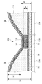
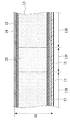
図7は図6のVII-VII線による断面形状、図8は図6のVIII-VIII線による断面形状、図9は図6のIX-IX線による断面形状、図10は図6のX-X線による断面形状、をそれぞれ拡大した模式図である。また、図7から図10の断面図において、吸収体13の密度の高さをドットの疎密で表現している。
図7に示されるように、凹部21付近の断面形状は、開口端部が底部よりも広がっている。符号13Dで表される部分は、吸収体13のうち高坪量であり、且つ、圧搾されている高坪量・圧搾部である。符号13Eで表される部分は、吸収体13のうち高坪量であり、且つ、圧搾されていない高坪量・非圧搾部である。すなわち、高坪量・圧搾部13Dは交差領域25以外の凹部21を表し、高坪量・非圧搾部13Eは主吸収領域26における吸収体13を表す。ここで、吸収体13は、上述したように、主にSAPとパルプからなるものであり、密度は主にパルプ繊維密度が関与している。したがって、高坪量・圧搾部13Dはパルプが圧縮され、パルプ間の隙間が少ない状態である一方、高坪量・非圧搾部13Eは、パルプ間の隙間が高坪量・圧搾部13Dに比べて多い状態である。
加えて、凹部21は、合成繊維であるトップシート14と主成分がパルプの吸収体13とを共に圧縮接合してフィルム状に形成されているので、凹部21の底面は、体液を吸収するまでは、圧縮列22の延在方向へ体液が拡散することを促進する。
図8に移り、本実施形態では、低坪量部23において、吸収体13は、トップシート14およびコアラップ15に接合されている。図9では、交差領域25の断面形状が示されている。符号13Fで表される部分は、吸収体13のうち低坪量であり、且つ、圧搾されていない低坪量・非圧搾部である。符号13Gで表される部分は、吸収体13のうち低坪量であり、且つ、圧搾されている低坪量・圧搾部である。すなわち、低坪量・非圧搾部13Fは低坪量部23のうち圧搾されていないものを表し、低坪量・圧搾部13Gは低坪量部23のうち圧搾されているものを表す。本実施形態では、図9に示すように、交差領域25における低坪量部23(低坪量・圧搾部13G)も凹部21と同じ厚みまで押込むものの、低坪量であるため、交差領域25以外の凹部21(高坪量・圧搾部13D)よりも低密度を維持することが可能となっている。すなわち、図9に示すように、交差領域25における吸収体13(低坪量・圧搾部13G)は、図8で示した低坪量・非圧搾部13Fよりは圧搾されるものの、交差領域25以外の凹部21(高坪量・圧搾部13D)よりは密度が低い。このように、吸収体13の交差領域25において、低密度を維持することと、厚さを減らすことが両立できるので、交差領域25において、柔らかさを保つことが可能となる。本実施形態では、交差領域25における吸収体13(低坪量・圧搾部13G)の密度が、交差領域25以外の圧縮列22が形成された領域の吸収体13(高坪量・圧搾部13D)の密度よりも低いものとなる。また、本発明では、交差領域25および/またはその周辺が柔らかくなるという効果を発揮するのであれば、低坪量部23の吸収体13の密度は、交差領域25の吸収体13の密度と等しい態様、または、当該密度より高い態様も許容するものである。本実施形態では、図10に示すように、交差領域25を含む圧縮列22が形成された底部における吸収体13の厚みは略一定となっているが、本発明ではこれに限られない。例えば、交差領域25の厚みだけ薄くなるように圧縮してもよい。つまり、低坪量部23が設けられた交差領域25において、圧縮列22の凹部21より深い凹部を設けてもよい。この構成により、低坪量部23の存在により交差領域25が柔らかくなるだけでなく、交差領域25が薄くなるので、交差領域25が折れ曲がりやすくなる。このとき、交差領域25における低坪量部23の吸収体13の密度は、その低坪量部23以外の圧縮列22の吸収体13の密度と等しく、または、該密度よりも高くなりうる。
図10に示すように、圧縮列22において、交差領域25を含む領域である圧縮列22の吸収体13の低坪量・圧搾部13Gの密度は、交差領域25を含まない領域である圧縮列22の凹部が形成された領域の吸収体の高坪量・圧搾部13Dの密度よりも低いものとなっている。
次にエンボス加工によるエンボスパターンの実施形態について、説明する。
図5に示すように、本実施形態のエンボスパターンは、連続的に延在した凹部21を複数並べた格子形状であり、格子1つの枡の対角線L1の長さが42mm(4.2cm)となるように凹部21が配置されている。また、図5および図6に示されるように、本実施形態のエンボスパターンは、第1圧縮列22aが間隔S1で平行に延在し、第2圧縮列22bが間隔S2で平行に延在している。そして、これら第1圧縮列22aと第2圧縮列22bとによって、斜め格子状となるエンボスパターンが形成される。本実施形態における格子の1辺の長さS1およびS2は等しく、29.7mmである。格子の間隔は、13.0mm以上54.0mm以下が好ましい。
ここで、吸収体13における凹部21の深さをD1、エンボス加工をする前の吸収体13とトップシート14との厚さ、すなわち、主吸収領域26における吸収体13とトップシート14からなる最大の厚みをD2、凹部21のおむつ10の厚みをD3、凹部21の吸収体13の厚みをD4とする。本実施形態では、厚みD2は、8.0mmであり、5.0mm~20.0mmが好ましい。また、本実施形態では、図7に示されるように、厚みD3は1.0mmである。なお、凹部21における吸収体13の厚みD4(図7を参照)は、0.2mm~0.6mmが好ましい。
そうすると、凹部21の深さD1は、厚みD2の42.5%~97.5%程度である。このように、本実施形態における凹部21は、エンボスロールによる押圧において、吸収体13をバックシート12方向へ圧縮して凹部21が形成されている。
本実施形態のエンボスパターンにおける交差領域25の吸収体13(低坪量・圧搾部13G)の密度は、0.8g/cm3であり、0.5g/cm3~1.2g/cm3が好ましい。また、本実施形態に係る交差領域25以外の凹部21の吸収体13(高坪量・圧搾部13D)の密度は、1.38g/cm3であり、0.8g/cm3~1.9g/cm3が好ましい。さらに、本実施形態に係る凹部21以外の吸収体13(高坪量・非圧搾部13E)の密度は、0.05g/cm3であり、0.03g/cm3~0.07g/cm3が好ましい。
このような密度分布で吸収体13を形成することにより、交差領域25の剛性を柔らかくすることができる。したがって、吸収体13に格子状のエンボスパターンが形成されていても、交差領域25が固くならずに折れやすくなり、着用者の使用感(柔らかさ)を向上させることができる。
各凹部21をこのような深さおよび間隔で形成することにより、体重が加わっても、その溝を維持することができるとともに、おむつの股下部の肌当接面において、柔らかい肌触りを維持することができる。したがって、斜め格子状のエンボスパターンにより、脚の様々な動きに対しておむつがよれるなど変形を抑制できるとともに、その肌触りを柔らかいものとして、肌への刺激を極力抑えることができる。
ここで、図6に示すように、薄くて中密度な交差領域25をQ1、薄くて高密度な圧縮列22を幅方向に挟んだ領域をQ2、厚くて低密度な主吸収領域26をQ3、薄くて高密度な圧縮列22の延在方向に沿った領域をQ4とする。このような密度分布のおむつ10の剛性(曲げにくさ、曲げ強度)の序列は、柔らかい(かつ折れ曲がりやすい)部分から硬い(かつ折れ曲がりにくい)部分へ、領域Q1<領域Q3<領域Q2<領域Q4、の序列にすることができる。
このように、吸収体13の剛性を、薄くて高密度な圧縮列22の延在方向に沿った領域Q4が最も硬く形成された中で、交差領域25を挟む方向には、やわらかくすることにより、着用者がおむつ10を着用して動いた際に、おむつ10が着用者の体から離れる方向に膨らみ、着用者の体とおむつ10との間に空間を保つようにおむつ10を変形させることができる。これにより、吸収体13に格子状のエンボスパターンが形成されていても、交差領域25が固くならずに折れやすくなり、着用者の使用感(柔らかさ)を向上させることができる。加えて、交差領域25を柔らかくすることにより、着用者の動きによって交差領域25で吸収体13が破れやすくなるのを防止することができる。
[変形例]
本発明は、上述した実施形態に限られることなく、本発明の技術的思想から逸脱しない範囲で、適宜の変更や変形が可能である。
本発明は、上述した実施形態に限られることなく、本発明の技術的思想から逸脱しない範囲で、適宜の変更や変形が可能である。
例えば、上記実施形態では、エンボス加工はエンボスロールを用いて行うものを説明したが、この方法に限らず、おむつの大きさに合わせた板状のエンボス板によって、おむつの大きさ単位でエンボスを押していくものなどでもよい。
加えて、吸収体13を親水性シートによってくるんだ後トップシート14を配したものだけでなく、吸収体13の上に直接、トップシート14を配したものであってもよい。また、トップシート14と親水性シートとの間に、液拡散性を向上させる液拡散シートを設けてもよい。このシートにより、体液はより拡散しやすくなる。また、親水性シートは、吸収体13をくるむように取り付けられてもよいし、単に、吸収体13の端部をくるむことなく、表、裏に重ねて配置されたものであってもよい。
また、上記実施形態では、連続する溝である凹部21によって圧縮列22を形成しているが、不連続な(例えば間欠的な)溝によって圧縮列22を形成するようにしてもよい(後述の変形例を参照)。なお、凹部21の形状は本実施形態に示した形状に限らず、四角形、円形、楕円形、三角形など様々な形状を取り得る。
上記実施形態に係る使い捨ておむつ10は、大人用、子供用のいずれにも適用可能である。また、上記実施形態では、展開型おむつ10(いわゆるテープ型おむつ)を例にして説明したが、パンツ型おむつにも適用可能であるのはいうまでもない。また、本発明の吸収性物品はおむつのみに特定されるものではなく、吸収パッドや尿漏れパッド等、他の一般的な各種吸収性物品全般に適用されるものである。例えば、図5に示されるように、吸収体13およびトップシート14部分の構造から、本発明は、吸収パッド等にも適用可能であり、おむつと同様の作用効果を有するものである。
上記実施形態では、吸収体13の片面のみをエンボス加工しているがこれに限られず、両面エンボス加工を採用しても良い。つまり、トップシート14側およびバックシート12側の両面からのエンボス加工によって、吸収体13の表面と裏面の両面に凹部21が形成させる。これにより、吸収体13の表と裏のうち、片方の表面だけに圧力を集中させないため、エンボス加工の際に深くプレスしなくても圧縮列22を明確に形成し、かつ、おむつ10のしなやかさを保つことができる。
また、上記実施形態では、凹部21が連続して形成されているが、本発明では、凹部21は不連続に形成されてもよい。これにより、交差領域25における低坪量部23(低坪量・圧搾部13G)の形状も変化する。図11は、本発明の変形例に係る、図6のX-X線での断面図である。本変形例に係るおむつを構成する各要素のうち、同様の機能を有するものについては、上記実施形態と同一の符号を付してその説明を省略する。
本変形例では、圧縮列22が交差する交差領域25に該当する部分に凹部21が形成されない。そうすると、図11に示すように、交差領域25における低坪量部23(低坪量・圧搾部13G)は圧搾されず、交差領域25周辺の凹部21の圧搾に伴って少し圧縮され、断面視において肌当接側に少し盛り上がるように形成される(上記実施形態の図6を比較参照)。この構成により、交差領域25における吸収体13の密度が、凹部21の密度より低くなるため、上記実施形態と同様の効果を得ることができる。
また、上記実施形態では、図3や図8に示すように、低坪量部23とコアラップ15とが接合されているが、本発明では、接合されていなくてもよい。この配置によって、吸収体13を圧搾する際、交差領域25において凹部21が形成されるときに、低坪量部23が形成された部分が圧搾されない(または圧搾されにくい)ようにしてもよい。
10 使い捨ておむつ
10A ファスニングテープ
10B フロントパッチシート
10F 前身頃領域
10R 後身頃領域
10C 股下領域
10W ウエスト周り開口部
10L 脚周り開口部
10D 弾性シート
11 カバーシート
11A、13A 切欠き部
12 バックシート(裏面シート)
13 吸収体
14 トップシート(表面シート)
15 コアラップ
16、19 糸ゴム
18 サイドシート
21 凹部
21a 右向き凹部(第1方向に傾斜した凹部)
21b 左向き凹部(第2方向に傾斜した凹部)
22 圧縮列
22a 第1圧縮列
22b 第2圧縮列
23 低坪量部
24c 低坪量列
25 交差領域
26 主吸収領域
S1 複数の第1圧縮列の形成間隔
S2 複数の第2圧縮列の形成間隔
D1 凹部の深さ
D2 主吸収領域の厚み
D3 凹部におけるおむつの厚み
D4 凹部における吸収体の厚み
L1 1つの枡の対角線
L2 隣接する低坪量列24cの間隔
10A ファスニングテープ
10B フロントパッチシート
10F 前身頃領域
10R 後身頃領域
10C 股下領域
10W ウエスト周り開口部
10L 脚周り開口部
10D 弾性シート
11 カバーシート
11A、13A 切欠き部
12 バックシート(裏面シート)
13 吸収体
14 トップシート(表面シート)
15 コアラップ
16、19 糸ゴム
18 サイドシート
21 凹部
21a 右向き凹部(第1方向に傾斜した凹部)
21b 左向き凹部(第2方向に傾斜した凹部)
22 圧縮列
22a 第1圧縮列
22b 第2圧縮列
23 低坪量部
24c 低坪量列
25 交差領域
26 主吸収領域
S1 複数の第1圧縮列の形成間隔
S2 複数の第2圧縮列の形成間隔
D1 凹部の深さ
D2 主吸収領域の厚み
D3 凹部におけるおむつの厚み
D4 凹部における吸収体の厚み
L1 1つの枡の対角線
L2 隣接する低坪量列24cの間隔
Claims (5)
- 液透過性の表面シートと、液不透過性の裏面シートと、前記表面シートと前記裏面シートとの間に配された吸収体とを備える吸収性物品であって、
前記吸収体を圧縮して形成された複数の凹部で構成され、かつ相互に交差する圧縮列が複数配列し、
前記圧縮列の交差領域および/または該交差領域の周辺には、低坪量部が設けられることを特徴とする吸収性物品。 - 前記交差領域における前記低坪量部の吸収体の密度は、前記低坪量部以外の前記圧縮列が形成された領域の吸収体の密度よりも低いことを特徴とする請求項1に記載の吸収性物品。
- 前記交差領域における前記低坪量部の吸収体の密度は、前記低坪量部以外の前記圧縮列が形成された領域の吸収体の密度と等しい、または、該密度よりも高いことを特徴とする請求項1に記載の吸収性物品。
- 前記複数の凹部は、前記表面シート側に、前記表面シートと前記吸収体とを圧縮して形成されたことを特徴とする請求項1ないし3のいずれか1項に記載の吸収性物品。
- 前記複数の凹部は、連続する溝であることを特徴とする請求項1ないし4のいずれか1項に記載の吸収性物品。
Priority Applications (2)
| Application Number | Priority Date | Filing Date | Title |
|---|---|---|---|
| CN201780025901.8A CN109069328B (zh) | 2016-04-26 | 2017-04-07 | 吸收性物品 |
| RU2018141265A RU2713974C1 (ru) | 2016-04-26 | 2017-04-07 | Впитывающее изделие |
Applications Claiming Priority (2)
| Application Number | Priority Date | Filing Date | Title |
|---|---|---|---|
| JP2016-088473 | 2016-04-26 | ||
| JP2016088473A JP6380452B2 (ja) | 2016-04-26 | 2016-04-26 | 吸収性物品 |
Publications (1)
| Publication Number | Publication Date |
|---|---|
| WO2017187944A1 true WO2017187944A1 (ja) | 2017-11-02 |
Family
ID=60160495
Family Applications (1)
| Application Number | Title | Priority Date | Filing Date |
|---|---|---|---|
| PCT/JP2017/014579 Ceased WO2017187944A1 (ja) | 2016-04-26 | 2017-04-07 | 吸収性物品 |
Country Status (5)
| Country | Link |
|---|---|
| JP (1) | JP6380452B2 (ja) |
| CN (1) | CN109069328B (ja) |
| RU (1) | RU2713974C1 (ja) |
| TW (1) | TWI642417B (ja) |
| WO (1) | WO2017187944A1 (ja) |
Families Citing this family (3)
| Publication number | Priority date | Publication date | Assignee | Title |
|---|---|---|---|---|
| CN109893345B (zh) * | 2017-12-11 | 2022-04-12 | 花王株式会社 | 吸收性物品 |
| CN112912046B (zh) * | 2018-09-27 | 2023-01-31 | 宝洁公司 | 具有视觉可辨别的图案的非织造纤维网 |
| US11999150B2 (en) * | 2019-05-03 | 2024-06-04 | The Procter & Gamble Company | Nonwoven webs with one or more repeat units |
Citations (5)
| Publication number | Priority date | Publication date | Assignee | Title |
|---|---|---|---|---|
| JP2009131417A (ja) * | 2007-11-29 | 2009-06-18 | Kao Corp | 吸収性物品及びこの製造方法 |
| JP2012075566A (ja) * | 2010-09-30 | 2012-04-19 | Unicharm Corp | パンツ型オムツ |
| JP2013255562A (ja) * | 2012-06-11 | 2013-12-26 | Kao Corp | 吸収性物品 |
| JP2015016218A (ja) * | 2013-07-12 | 2015-01-29 | ユニ・チャーム株式会社 | 使い捨ておむつ |
| JP5875730B1 (ja) * | 2015-09-10 | 2016-03-02 | ユニ・チャーム株式会社 | 吸収パッド |
Family Cites Families (17)
| Publication number | Priority date | Publication date | Assignee | Title |
|---|---|---|---|---|
| US4834735A (en) * | 1986-07-18 | 1989-05-30 | The Proctor & Gamble Company | High density absorbent members having lower density and lower basis weight acquisition zones |
| JP4198849B2 (ja) * | 1998-12-01 | 2008-12-17 | ユニ・チャーム株式会社 | 吸収性物品 |
| JP3639451B2 (ja) * | 1999-01-20 | 2005-04-20 | ユニ・チャーム株式会社 | 生理用ナプキン |
| JP4324375B2 (ja) * | 2002-12-27 | 2009-09-02 | ユニ・チャーム株式会社 | 圧縮溝と可撓部とを備えた吸収性物品 |
| US20100036348A1 (en) * | 2008-08-05 | 2010-02-11 | Antonio Carlos Ribeiro De Carvalho | Absorbent article including absorbent core having a plurality of first regions and a second region surrounding each of the first regions |
| US7994385B2 (en) * | 2008-08-05 | 2011-08-09 | Johnson & Johnson Ind. E Com. Ltda | Absorbent article including absorbent core having concentrically arranged absorbent regions |
| JP2010136899A (ja) * | 2008-12-11 | 2010-06-24 | Kao Corp | 吸収性物品用の吸収体 |
| JP5452960B2 (ja) * | 2009-03-31 | 2014-03-26 | ユニ・チャーム株式会社 | 吸収性物品及び吸収性物品の製造方法 |
| US8034991B2 (en) * | 2009-04-29 | 2011-10-11 | Johnson & Johnson Ind. E Com. Ltda | Absorbent article including a plurality of longitudinally extending channels |
| JP5665338B2 (ja) * | 2010-03-24 | 2015-02-04 | ユニ・チャーム株式会社 | 体液処理用品およびその製法 |
| EP2581067B1 (en) * | 2010-06-10 | 2017-04-26 | Kao Corporation | Process for production of absorber |
| JP5764320B2 (ja) * | 2010-12-22 | 2015-08-19 | 花王株式会社 | 吸収体の製造方法 |
| JP5795493B2 (ja) * | 2011-05-20 | 2015-10-14 | 花王株式会社 | 吸収性物品 |
| JP6050612B2 (ja) * | 2012-06-11 | 2016-12-21 | 花王株式会社 | 吸収性物品 |
| JP6012270B2 (ja) * | 2012-06-11 | 2016-10-25 | 花王株式会社 | 吸収性物品 |
| US10555843B2 (en) * | 2014-06-13 | 2020-02-11 | Daio Paper Corporation | Absorbent article |
| EA033233B1 (ru) * | 2014-10-03 | 2019-09-30 | Одзи Холдингз Корпорейшн | Впитывающее изделие |
-
2016
- 2016-04-26 JP JP2016088473A patent/JP6380452B2/ja not_active Expired - Fee Related
-
2017
- 2017-04-07 CN CN201780025901.8A patent/CN109069328B/zh not_active Expired - Fee Related
- 2017-04-07 RU RU2018141265A patent/RU2713974C1/ru active
- 2017-04-07 TW TW106111720A patent/TWI642417B/zh not_active IP Right Cessation
- 2017-04-07 WO PCT/JP2017/014579 patent/WO2017187944A1/ja not_active Ceased
Patent Citations (5)
| Publication number | Priority date | Publication date | Assignee | Title |
|---|---|---|---|---|
| JP2009131417A (ja) * | 2007-11-29 | 2009-06-18 | Kao Corp | 吸収性物品及びこの製造方法 |
| JP2012075566A (ja) * | 2010-09-30 | 2012-04-19 | Unicharm Corp | パンツ型オムツ |
| JP2013255562A (ja) * | 2012-06-11 | 2013-12-26 | Kao Corp | 吸収性物品 |
| JP2015016218A (ja) * | 2013-07-12 | 2015-01-29 | ユニ・チャーム株式会社 | 使い捨ておむつ |
| JP5875730B1 (ja) * | 2015-09-10 | 2016-03-02 | ユニ・チャーム株式会社 | 吸収パッド |
Also Published As
| Publication number | Publication date |
|---|---|
| TWI642417B (zh) | 2018-12-01 |
| CN109069328B (zh) | 2022-03-04 |
| CN109069328A (zh) | 2018-12-21 |
| JP2017196064A (ja) | 2017-11-02 |
| TW201740892A (zh) | 2017-12-01 |
| RU2713974C1 (ru) | 2020-02-11 |
| JP6380452B2 (ja) | 2018-08-29 |
Similar Documents
| Publication | Publication Date | Title |
|---|---|---|
| US11110012B2 (en) | Disposable absorbent article with profiled absorbent core | |
| WO2016092843A1 (ja) | 吸収性物品 | |
| JP6785231B2 (ja) | 吸収性物品 | |
| CN107072841B (zh) | 吸收性物品 | |
| JP6674322B2 (ja) | 吸収性物品 | |
| JP6380452B2 (ja) | 吸収性物品 | |
| JP6380454B2 (ja) | 吸収性物品 | |
| JP6558281B2 (ja) | 吸収性物品、その製造装置および製造方法 | |
| JP6610732B2 (ja) | 吸収性物品 | |
| JP6365406B2 (ja) | 吸収性物品 | |
| JP6610733B2 (ja) | 吸収性物品 | |
| JP6939864B2 (ja) | 吸収性物品 | |
| JP2018000472A (ja) | 吸収性物品および吸収性物品の製造方法 | |
| JP6617593B2 (ja) | 吸収性物品 | |
| JP6607070B2 (ja) | 吸収性物品 | |
| JP6503877B2 (ja) | 吸収性物品 | |
| JP2016106992A (ja) | 吸収性物品 | |
| JP2016214405A (ja) | 吸収性物品 | |
| JP2016106991A (ja) | 吸収性物品 | |
| WO2016185705A1 (ja) | 吸収性物品、その製造装置および製造方法 | |
| JP2019024607A (ja) | 吸収性物品 | |
| HK1236797A1 (en) | Absorbent article |
Legal Events
| Date | Code | Title | Description |
|---|---|---|---|
| NENP | Non-entry into the national phase |
Ref country code: DE |
|
| 121 | Ep: the epo has been informed by wipo that ep was designated in this application |
Ref document number: 17789231 Country of ref document: EP Kind code of ref document: A1 |
|
| 122 | Ep: pct application non-entry in european phase |
Ref document number: 17789231 Country of ref document: EP Kind code of ref document: A1 |