WO2017187860A1 - Rotary electric machine - Google Patents
Rotary electric machine Download PDFInfo
- Publication number
- WO2017187860A1 WO2017187860A1 PCT/JP2017/012217 JP2017012217W WO2017187860A1 WO 2017187860 A1 WO2017187860 A1 WO 2017187860A1 JP 2017012217 W JP2017012217 W JP 2017012217W WO 2017187860 A1 WO2017187860 A1 WO 2017187860A1
- Authority
- WO
- WIPO (PCT)
- Prior art keywords
- winding
- teeth
- turns
- windings
- lead wire
- Prior art date
Links
Images


Classifications
-
- H—ELECTRICITY
- H02—GENERATION; CONVERSION OR DISTRIBUTION OF ELECTRIC POWER
- H02K—DYNAMO-ELECTRIC MACHINES
- H02K3/00—Details of windings
- H02K3/04—Windings characterised by the conductor shape, form or construction, e.g. with bar conductors
- H02K3/28—Layout of windings or of connections between windings
-
- H—ELECTRICITY
- H02—GENERATION; CONVERSION OR DISTRIBUTION OF ELECTRIC POWER
- H02K—DYNAMO-ELECTRIC MACHINES
- H02K1/00—Details of the magnetic circuit
- H02K1/06—Details of the magnetic circuit characterised by the shape, form or construction
- H02K1/12—Stationary parts of the magnetic circuit
- H02K1/14—Stator cores with salient poles
- H02K1/146—Stator cores with salient poles consisting of a generally annular yoke with salient poles
-
- H—ELECTRICITY
- H02—GENERATION; CONVERSION OR DISTRIBUTION OF ELECTRIC POWER
- H02K—DYNAMO-ELECTRIC MACHINES
- H02K1/00—Details of the magnetic circuit
- H02K1/06—Details of the magnetic circuit characterised by the shape, form or construction
- H02K1/22—Rotating parts of the magnetic circuit
- H02K1/27—Rotor cores with permanent magnets
- H02K1/2706—Inner rotors
- H02K1/272—Inner rotors the magnetisation axis of the magnets being perpendicular to the rotor axis
- H02K1/274—Inner rotors the magnetisation axis of the magnets being perpendicular to the rotor axis the rotor consisting of two or more circumferentially positioned magnets
- H02K1/2753—Inner rotors the magnetisation axis of the magnets being perpendicular to the rotor axis the rotor consisting of two or more circumferentially positioned magnets the rotor consisting of magnets or groups of magnets arranged with alternating polarity
- H02K1/278—Surface mounted magnets; Inset magnets
-
- H—ELECTRICITY
- H02—GENERATION; CONVERSION OR DISTRIBUTION OF ELECTRIC POWER
- H02K—DYNAMO-ELECTRIC MACHINES
- H02K15/00—Methods or apparatus specially adapted for manufacturing, assembling, maintaining or repairing of dynamo-electric machines
- H02K15/04—Methods or apparatus specially adapted for manufacturing, assembling, maintaining or repairing of dynamo-electric machines of windings, prior to mounting into machines
-
- H—ELECTRICITY
- H02—GENERATION; CONVERSION OR DISTRIBUTION OF ELECTRIC POWER
- H02K—DYNAMO-ELECTRIC MACHINES
- H02K21/00—Synchronous motors having permanent magnets; Synchronous generators having permanent magnets
- H02K21/12—Synchronous motors having permanent magnets; Synchronous generators having permanent magnets with stationary armatures and rotating magnets
- H02K21/14—Synchronous motors having permanent magnets; Synchronous generators having permanent magnets with stationary armatures and rotating magnets with magnets rotating within the armatures
- H02K21/16—Synchronous motors having permanent magnets; Synchronous generators having permanent magnets with stationary armatures and rotating magnets with magnets rotating within the armatures having annular armature cores with salient poles
-
- H—ELECTRICITY
- H02—GENERATION; CONVERSION OR DISTRIBUTION OF ELECTRIC POWER
- H02K—DYNAMO-ELECTRIC MACHINES
- H02K3/00—Details of windings
- H02K3/04—Windings characterised by the conductor shape, form or construction, e.g. with bar conductors
- H02K3/18—Windings for salient poles
-
- H—ELECTRICITY
- H02—GENERATION; CONVERSION OR DISTRIBUTION OF ELECTRIC POWER
- H02K—DYNAMO-ELECTRIC MACHINES
- H02K3/00—Details of windings
- H02K3/46—Fastening of windings on the stator or rotor structure
- H02K3/52—Fastening salient pole windings or connections thereto
- H02K3/521—Fastening salient pole windings or connections thereto applicable to stators only
- H02K3/522—Fastening salient pole windings or connections thereto applicable to stators only for generally annular cores with salient poles
-
- H—ELECTRICITY
- H02—GENERATION; CONVERSION OR DISTRIBUTION OF ELECTRIC POWER
- H02K—DYNAMO-ELECTRIC MACHINES
- H02K2203/00—Specific aspects not provided for in the other groups of this subclass relating to the windings
- H02K2203/06—Machines characterised by the wiring leads, i.e. conducting wires for connecting the winding terminations
-
- H—ELECTRICITY
- H02—GENERATION; CONVERSION OR DISTRIBUTION OF ELECTRIC POWER
- H02K—DYNAMO-ELECTRIC MACHINES
- H02K29/00—Motors or generators having non-mechanical commutating devices, e.g. discharge tubes or semiconductor devices
- H02K29/03—Motors or generators having non-mechanical commutating devices, e.g. discharge tubes or semiconductor devices with a magnetic circuit specially adapted for avoiding torque ripples or self-starting problems
Definitions
- the present invention relates to a permanent magnet type concentrated winding brushless motor and an electric auxiliary system for an automobile such as an electric power steering device using the same.
- EPS Electrospherical power steering
- the driver feels the torque pulsation of the motor through the steering wheel. Therefore, in the EPS motor, it is necessary to reduce the cogging torque to about 1/1000 of the assist torque by the motor and the torque pulsation to about 1% of the assist torque.
- Motor-induced vibration sources that can cause vibration and noise in the passenger compartment include torque fluctuation components (cogging torque and torque pulsation) caused by the motor and electromagnetic excitation force generated between the stator and rotor of the motor. .
- the former propagates through the output shaft of the motor, and the vibration energy of the motor due to the latter propagates into the passenger compartment through the mechanical parts of the EPS device. These are emitted as radiated sound in the passenger compartment and become noise.
- a similar mechanism generates noise in the passenger compartment for electrical components other than EPS devices.
- the price of the motor consists of the cost of materials such as magnets and windings and the cost associated with manufacturing. For this reason, it is desirable that the motor has a high output density, a large ratio of output to size and magnet mass, and can suppress material costs. A motor that is easy to manufacture and requires less manpower and manufacturing equipment is desirable.
- the cogging torque and torque pulsation can be reduced due to the high rotation order, but the electromagnetic excitation force It is known that vibration is a problem because the spatial order is second order. In motors with a ratio of pole number to slot number of 8:12, the spatial order of electromagnetic excitation force is fourth order and vibration is small, but it is known that the technology to reduce cogging torque and torque pulsation is an issue. ing.
- Patent Document 1 Japanese Patent Application Laid-Open No. Sho 62-110468
- Patent Document 2 Japanese Patent Application Laid-Open No. 9-177622
- the winding coefficient is 0.902, which is larger than an 8:12 motor. It is described that the order of the cogging torque is 126 and small.
- Non-Patent Document 1 describes the arrangement of the three-phase windings of the motor with the winding coefficient of 0.902, and describes that a motor with a winding coefficient of 0.902 can be configured by connecting the three phases. ing. This connection may be configured in any of 6 series, 3 series, 2 parallels, 2 series, 3 parallels, and 6 parallels with respect to the winding of one of the three phases.
- the winding is wound around the teeth of the stator core laminated in the rotation axis direction.
- the lead wire to the power source or the neutral point and the connecting wire for crossing the teeth farther from the adjacent when the plurality of teeth are wound in series are arranged at the ends of the teeth in the axial direction.
- Patent Document 3 and Patent Document 4 in the arrangement of the three-phase winding described in Non-Patent Document 1, the lead wire and the jumper wire are arranged at the winding end on the same side in the rotation axis direction. An example is described.
- Patent Document 5 describes an example in which the lead wire and the jumper wire are arranged at the winding end on the same side in the rotation axis direction in the arrangement of the three-phase windings described in Non-Patent Document 1.
- the space secondary electromagnetic excitation force has a smaller ratio of the number of poles to the number of slots than a 10:12 motor.
- the winding of one of the three phases may be configured in either 6 series, 3 series 2 parallel, 2 series 3 parallel, or 6 parallel, but 6 series, 3 series Two parallels are usually used.
- the operation of connecting 6 to 12 lead wires and adjacent It is necessary to connect 6 to 18 crossover wires to more distant teeth or store them at the winding end, and space is limited at the same winding end. The complexity of the procedure and the increased manufacturing costs due to the additional components are problematic.
- the lead wire and the connecting wire are arranged on the same side of the rotating shaft because the number of windings of each tooth is an integer.
- the number of turns is an integer, the winding end at the beginning of winding and the winding end at the end of winding are on the same side.
- the number of turns is a half integer
- the winding end at the beginning of winding and the winding end at the end of winding are on the opposite side.
- the number of turns of each tooth is the same, but when winding two teeth in series, if the number of turns is set to a half integer, the lead wire and the connecting wire to the teeth farther away from the adjacent line are reversed. Can be placed at the winding end on the side.
- the present invention has been made in view of such a background, and an object of the present invention is to improve the efficiency of manufacturing work related to winding in a concentrated winding brushless motor.
- the above-mentioned problem is that the number of windings of the teeth connected to the lead wire is a half integer, or the winding of the tooth connected to the lead wire. If there is a winding connected adjacent to the wire, the total number of turns is a half integer, and the tooth winding connected to the lead wire or the tooth winding connected adjacent thereto is The number of turns of the tooth winding connected farther than the adjacent by the crossover wire, or the total number of teeth winding connected adjacent to the tooth winding connected farther than the adjacent by the crossover wire This can be solved by a stator winding wound so that the number of turns is an integer.
- the lead wire and the connecting wire to the teeth farther than the adjacent wires can be arranged at the winding end on the opposite side in the axial direction, so that the manufacturing work related to the winding can be made more efficient.
- mold concentrated winding motor. Includes phase arrangement of stator windings. It is a figure which shows Embodiment 1 of this invention, and is a figure explaining the connection between a stator coil
- the figure which shows Embodiment 2 of this invention is a figure explaining the example of a procedure which manufactures a stator avoiding interference of a crossover.
- the figure which shows Embodiment 2 of this invention is a figure explaining the example of a procedure which manufactures a stator avoiding interference of a crossover.
- Embodiment 4 of this invention It is a figure which shows Embodiment 4 of this invention, and is a figure explaining the connection between a stator coil
- the permanent magnet type brushless motor for EPS apparatus of a present Example is applicable also to other motor vehicle auxiliary equipment.
- the present invention can be applied to all industrial brushless motors for which low vibration is preferable.
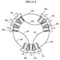
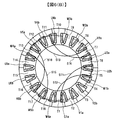
- FIG. 1 The phase of the wound teeth and the winding direction (or current direction) are as shown in FIG.
- FIG. 1 the teeth constituting the 18-slot stator are marked with a symbol.
- the symbols for the Dice symbols are T1, T2, T3, T4, T5, T6, T7, T8, T9, T10, T11, T12, T13, T14, T15, T16 in the order that they are adjacent in the counterclockwise direction. , T17, T18.
- the windings wound around each of the teeth are U1a, V1a, V2b, W1b, U2b, U3a, V3a, W2a, W3b, U4b, V4b, V5a, W4a, U5a, U6b, V6b, W5b, W6a, respectively. It distinguishes by attaching a symbol.
- the symbols U, V, and W represent the U phase, V phase, and W phase, the numbers indicate the number of each phase that appears along the teeth, and a and b are the winding direction (or current direction).
- a set of windings at rotationally symmetrical positions every 60 °: V2b, U3a, W3b, V5a, U6b, W6a are set as set C.
- the sets A, B, and C can be wound with different numbers of turns.
- the balance of the three-phase magnetomotive force is not lost, and the torque fluctuation / excitation force does not deteriorate.
- the number of windings in series is 3 or more and the influence of torque fluctuation / exciting force due to the difference in the number of windings is small, it is possible to connect to the teeth far away from the lead wire and adjacent to the teeth.
- the connecting wire at the winding end on the opposite side in the axial direction it may be wound with a different number of turns.
- U5a, U1a, U3a are three series windings, and similarly V1a, V3a, V5a and W2a, W4a, W6a are three series windings, and these are type a three series windings. Further, U2b, U4b, and U6b are three series windings. Similarly, V4b, V6b, and V2b and W5b, W1b, and W3b are three series windings, and these are three series windings of type b. In each of the three series windings, the number of turns of the three series windings is set to a half integer Na, an integer N, and a half integer Nb in this order.
- the number of turns of set A U1a, W1b, V3a, U4b, W4a, V6b is an integer N
- the number of turns of set B V1a, U2b, W2a, V4b, U5a, W5b is a half-integer Na
- Set C The number of turns of V2b, U3a, W3b, V5a, U6b, W6a is a half integer Nb, and the number of turns is the same in each set.
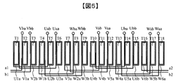
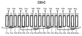
- FIG. 2 is a diagram in which the circumferential arrangement of the teeth and windings in FIG. 1 is developed and arranged in a straight line with T1 on the left side and T18 on the right side.
- the vertical direction of FIG. 2 is the direction of the rotation axis, and the lead wire is arranged at the upper end of the winding wound around the teeth, and the jumper is arranged at the lower end. .
- Fig. 2 on the lead wire of the winding, add a symbol using each phase of U, V, W, winding type of a, b, forward / reverse current direction (a, b) one character at a time, Distinguish.
- the winding V1a connected to the lead wire Vaa has a half-integer number of Na turns
- the connecting wire is on the opposite side of Vaa and crosses the winding V3a
- V3a has an integer N turns
- the crossover wire is opposite to Vaa and crosses over the winding V5a. Since V5a is a half integer Nb number of turns, the lead wire Vab is on the same side as Vaa.
- reference symbols a1 and a2 in FIG. 2 indicate that the crossover lines are connected by a1 and a2.
- FIGS. 3 (A) and 3 (B) are front views of the winding end portion as viewed from the crossover side (upper side) in an example in which the split core is inserted and assembled with the lead wire down. Yes, the arrangement of the inserted split core windings and crossovers is shown.
- a split core including three series windings of U5a, U1a, and U3a and teeth of T14, T1, and T6 is disposed.
- a split core including three series windings of V1a, V3a and V5a and teeth of T2, T7 and T12 is arranged.
- a split core including three series windings W2a, W4a, and W6a and teeth T8, T12, and T18 is disposed.
- the connecting wires 501 and 502 of the three series windings U5a, U1a, and U3a are arranged when the V-phase V1a split core is arranged and the W-phase W6a split core. Interfere with the placement. Therefore, by deforming the connecting wires 501 and 502 toward the inner diameter side, it is possible to arrange the V-phase split core of V1a and the split core of W-phase W6a.
- the crossover 503 between V3a and V5a interferes when the W-phase split core of W phase is arranged. Therefore, by dividing the connecting wire 503 toward the inner diameter side, the W-phase W2a split core can be arranged.
- the other connecting wires 504, 505 and 506 can be arranged at the winding end without being deformed.
- FIG. 3A shows the arrangement at this point.
- a split core including three series windings of U2b, U4b, and U6b and teeth of T5, T10, and T15 is arranged.
- Fifth, a split core including three series windings of V4b, V6b, and V2b and teeth of T11, T16, and T3 is arranged.
- Sixth, a split core including three series windings of W5b, W1b, and W3b and teeth of T17, T4, and T9 is arranged.
- the connecting lines of the U2b, U4b, and U6b three series windings are arranged when the V-phase V4b divided core is arranged and the W-phase W3b divided core is arranged.
- a V-phase V4b split core and a W-phase W3b split core can be arranged.
- the crossover between V6b and V2b interferes when placing the W-phase W5b split core. Therefore, by dividing the inner diameter side, it is possible to arrange the W-phase W5b split core. After all the split cores are arranged as described above, the three crossover wires of type b deformed to the inner diameter side are arranged at the winding ends.
- FIG. 3 (B) shows the arrangement at this time, and the type b crossover at the winding end is indicated by a broken line. Finally, six crossover wires of type a deformed to the inner diameter side are arranged at the winding ends, and the assembly of the stator winding is completed. In the first example, there are nine connecting wires that are deformed and arranged at the winding end.
- the lead wire side only needs to be connected to the neutral point and the power supply terminal in the Y connection, or connected to the power supply terminal in the ⁇ connection, and the processing of the crossover line becomes unnecessary. Therefore, it is not necessary to use an additional member or a complicated processing procedure, so that work efficiency can be improved and manufacturing cost can be reduced.
- FIG. 4 (A) shows an example of the wiring arrangement of two parallel Y-connections when using the three series windings and the number of turns.
- a Y-connection is composed of only type-a three series windings
- a Y-connection is composed of only type-b three series windings, and both external terminals are connected in parallel.
- U5a of type 3 series winding U5a, U1a, U3a is placed on the lead side, U3a is placed on the neutral point side, and the other three series windings are also on the lead side and neutral point side. If the above arrangement is taken, the connection arrangement on the left side of FIG.
- the lead lines Uab, Vab, and Wab in FIG. 2 are connected to the neutral point 301, and the lead lines Uaa, Vaa, and Waa in FIG. 2 are lead lines to the power source. Since the Y-connection is constituted by three type b series windings, the description is omitted.
- FIG. 4 (B) shows an example of the wiring arrangement of two parallel ⁇ connections when the three series windings and the number of turns are used.
- the ⁇ connection is composed of only the three series windings of type a
- the ⁇ connection is composed of only the three series windings of type b, and both external terminals are connected in parallel.
- the lead wire Uaa of type 3 series windings U5a, U1a, U3a and the lead wire Wab of W2a, W4a, W6a are connected to a terminal 351.
- the lead wire Uab of U5a, U1a, U3a and the lead wire Vaa of V1a, V3a, V5a are connected to the terminal 352.
- the lead wires Vab of V1a, V3a, V5a and the lead wires Waa of W2a, W4a, W6a are connected to the terminal 353.
- FIG. 4 (C) shows an example of the wiring arrangement of the series Y connection when using the three series windings and the number of turns.
- the U5a of the three series windings U5a, U1a, and U3a of type a is arranged on the lead side, Uab and Uba are connected to form 6 series, and Ubb is connected to the neutral point 303.
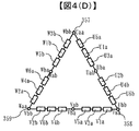
- FIG. 4 (D) shows an example of the winding arrangement in the series ⁇ connection when the three series windings and the number of turns are used.
- Connect the lead wire Uab of the three series windings U5a, U1a, U3a of type a to the lead wire Uba of the three series windings U2b, U4b, U6b of the type b, and lead wires Vab of V1a, V3a, V5a Is connected to the lead wire Vba of V4b, V6b, V2b, and the lead wire Wab of W2a, W4a, W6a is connected to the lead wire Wba of W5b, W1b, W3b to form 6 series.
- a series ⁇ connection can be configured by connecting the terminal 357 to the U-phase power supply terminal, connecting the terminal 358 to the V-phase power supply terminal, and connecting the terminal 359 to the W-phase power supply terminal.
- U3a, U1a, U2b are three series windings, and similarly V5a, V3a, V4b and W6a, W4a, W5b are three series windings, and these are three series windings of type a. Also, U6b, U4b, U5a are three series windings, and similarly V2b, V6b, V1a and W3b, W1b, W2a are three series windings, which are type b three series windings.
- the number of turns of the three series windings is, in this order, half integer Na, integer N, and half integer Nb.
- the number of turns of the set A: U1a, W1b, V3a, U4b, W4a, V6b is an integer N
- the number of turns of the set B: V1a, U2b, W2a, V4b, U5a, W5b is a half integer Nb
- Set C The number of turns of V2b, U3a, W3b, V5a, U6b, and W6a is a half integer Na, and the number of turns is the same in each set.
- the lead wires of the winding are distinguished from each other by using symbols for U, V and W phases, a and b winding types, and forward and reverse current directions (a and b) one by one.
- the winding V5a connected to the lead wire Vaa has a half-integer number of Na turns
- the connecting wire is on the opposite side of Vaa and crosses the winding V3a
- V3a has an integer N turns
- the crossover wire is opposite to Vaa and crosses over the winding V4b. Since V4b is a half-integer Nb number of turns, the lead wire Vab is on the same side as Vaa.
- the lead wire and the connecting wire to the teeth farther from the adjacent can be arranged on the opposite side.
- 6 (A) and 6 (B) are front views of the winding end portion as viewed from the crossover side (upper side) in an example in which the split core is inserted and assembled with the lead wire down. Yes, the arrangement of the inserted split core windings and crossovers is shown.
- the type a crossover wires 511 to 516 are all deformed to the inner diameter side, and an example of a procedure for assembling the type b three series windings in the order of the U phase, the V phase, and the W phase is shown in FIG. Will be described.
- a split core including three series windings of U6b, U4b, and U5a is arranged, fifth, a split core including three series windings of V2b, V6b, and V1a is arranged, and sixth, W3b, W1b , Split cores including 3 series windings of W2a will be arranged.
- all the split cores can be arranged without interference between the connecting wires of the three series windings and the split cores.
- FIG. 6B shows the arrangement at this point.
- six crossover wires of type a deformed to the inner diameter side are arranged at the winding end, and the assembly of the stator winding is completed.
- the lead wire side only needs to be connected to the neutral point and the power supply terminal in the Y connection, or connected to the power supply terminal in the ⁇ connection, and the processing of the crossover line becomes unnecessary. Therefore, it is not necessary to use an additional member or a complicated processing procedure, so that work efficiency can be improved and manufacturing cost can be reduced.
- U3a, U2b, U1a are three series windings
- V5a, V4b, V3a and W6a, W5b, W4a are three series windings, and these are type a three series windings
- U6b, U5a, U4b are three series windings
- V2b, V1a, V6b and W3b, W2a, W1b are three series windings, and these are three series windings of type b.
- the number of turns of the three series windings is assumed to be an integer N, a half integer Na, and a half integer Nb in this order.
- the number of turns of the set A: U1a, W1b, V3a, U4b, W4a, V6b is a half integer Nb
- the set B: the number of turns of the V1a, U2b, W2a, V4b, U5a, W5b is a half integer Na
- the number of turns of the group C: V2b, U3a, W3b, V5a, U6b, W6a is an integer N, and the number of turns is the same in each group.
- the lead wire of the winding is distinguished by attaching a symbol using U, V, W phases, a, b winding type, and forward / reverse current direction (a, b) one character at a time. To do.
- the winding V5a connected to the lead wire Vaa is an integer N turns, so the connecting wire is on the same side as Vaa and goes to the adjacent winding V4b, and V4b is a half integer Na turns Therefore, the crossover line is opposite to Vaa and crosses over the winding V3a. Since V3a is a half-integer Nb number of turns, the lead wire Vab is on the same side as Vaa. At this time, the winding direction of V4b is opposite to V5a and V3a.
- the lead wire and the connecting wire to the teeth farther from the adjacent can be arranged on the opposite side.
- FIG. 8 is a front view of the winding end as viewed from the connecting wire side (upper side) in an example in which the split core is inserted and assembled with the lead wire down, and the inserted split core winding The crossover arrangement is shown.
- the type a crossover wires 521, 522, and 523 are all deformed to the inside diameter side, and an example of the procedure for assembling the type b three series windings in the order of U phase, V phase, and W phase.
- a split core including three series windings of U6b, U5a, and U4b is arranged, fifth, a split core including three series windings of V2b, V1a, and V6b is arranged, and sixth, W3b, W2a , Split cores including three W1b series windings are arranged.
- FIG. 8 shows the arrangement at this point.
- the lead wire side only needs to be connected to the neutral point and the power supply terminal in the Y connection, or connected to the power supply terminal in the ⁇ connection, and the processing of the crossover line becomes unnecessary. Therefore, it is not necessary to use an additional member or a complicated processing procedure, so that work efficiency can be improved and manufacturing cost can be reduced.
- U3a, U2b, U1a are three series windings, and similarly V5a, V4b, V3a and W6a, W5b, W4a are three series windings, and these are three series windings of type a.
- U6b, U5a, U4b are three series windings.
- V2b, V1a, V6b and W3b, W2a, W1b are three series windings, and these are three series windings of type b.
- the number of turns of the three series windings is set to a half integer Na, an integer N, and a half integer Nb in this order.
- the number of turns of set A U1a, W1b, V3a, U4b, W4a, V6b is a half integer Nb
- the number of turns of set B V1a, U2b, W2a, V4b, U5a, W5b is an integer N Yes
- set C The number of turns of V2b, U3a, W3b, V5a, U6b, W6a is a half integer Na, and the number of turns is the same in each set.
- the lead wire of the winding is distinguished by attaching a symbol using U, V, W phases, a, b winding type, and forward / reverse current direction (a, b) one character at a time. To do.
- the winding V5a connected to the lead wire Vaa has a half-integer number of Na turns, so the connecting wire is opposite to Vaa and goes to the adjacent winding V4b, and V4b is an integer N turns Therefore, the crossover line is opposite to Vaa and crosses over the winding V3a. Since V3a is a half-integer Nb number of turns, the lead wire Vab is on the same side as Vaa. At this time, the winding direction of V4b is opposite to V5a and V3a.
- the lead wire and the connecting wire to the teeth farther from the adjacent can be arranged on the opposite side.
- FIG. 10 is a front view of the winding end as viewed from the crossover side (upper side) in an example in which the split core is inserted and assembled with the lead wire down, and the inserted split core winding The crossover arrangement is shown.
- the connecting wires on the opposite side to the lead wire have six connecting wires to adjacent windings and six connecting wires to windings farther from the adjacent wires.
- a split core including three series windings of U6b, U5a, and U4b is arranged, fifth, a split core including three series windings of V2b, V1a, and V6b is arranged, and sixth, W3b, W2a , Split cores including three W1b series windings are arranged.
- all the split cores can be arranged without interference between the connecting wires of the three series windings and the split cores.
- FIG. 10 shows the arrangement at this point.
- the lead wire side only needs to be connected to the neutral point and the power supply terminal in the Y connection, or connected to the power supply terminal in the ⁇ connection, and the processing of the crossover line becomes unnecessary. Therefore, it is not necessary to use an additional member or a complicated processing procedure, so that work efficiency can be improved and manufacturing cost can be reduced.
Landscapes
- Engineering & Computer Science (AREA)
- Power Engineering (AREA)
- Manufacturing & Machinery (AREA)
- Windings For Motors And Generators (AREA)
Abstract
With respect to a permanent magnet-type concentrated winding brushless motor, the present invention addresses the problem of disposing lead wires and cross-over wires, which cross over to teeth farther than adjacent teeth, on a wiring end part on an axial direction opposite side, in order to make the production work related to winding more efficient. The foregoing problem is solved by a brushless motor comprising a concentrated winding stator and a permanent magnet-type rotor, wherein a stator winding is wound so that: the number of windings of winding wires for teeth connected to lead wires is made a half integer, or in a case where there are winding wires adjacent to the winding wires of the teeth connected to lead wires and connected thereto the total number of windings of such winding wires is made a half integer; and the number of windings of winding wires of teeth which are connected, using cross-over wires, farther than being adjacent to the winding wires of the teeth connected to the lead wires or the winding wires of teeth adjacent to such winding wires and connected thereto is made an integer, or the total number of windings of winding wires of teeth adjacent to the winding wires of the teeth which are connected, using cross-over wires, farther than being adjacent, and connected thereto is made an integer.
Description
本発明は、永久磁石式集中巻ブラシレスモータおよびこれを用いた電動パワーステアリング装置などの自動車用電動補機システムに関する。
The present invention relates to a permanent magnet type concentrated winding brushless motor and an electric auxiliary system for an automobile such as an electric power steering device using the same.
電動化による油圧の代替や、ハイブリッド自動車、電気自動車の市場拡大の流れを受けて、電動パワーステアリング(以下、EPS)装置の装着率が急速に増大している。
¡Electric power steering (hereinafter referred to as EPS) devices are rapidly increasing in response to the replacement of hydraulic pressure through electrification and the expansion of the market for hybrid and electric vehicles.
EPS装置では、電気モータがステアリングホイール操作をアシストすることから、運転者はステアリングホイールを介して、モータのトルク脈動を手に感じることになる。このため、EPS用モータでは、コギングトルクをモータによるアシストトルクの1/1000程度に、トルク脈動をアシストトルクの1%程度に小さくする必要がある。
In the EPS device, since the electric motor assists the steering wheel operation, the driver feels the torque pulsation of the motor through the steering wheel. Therefore, in the EPS motor, it is necessary to reduce the cogging torque to about 1/1000 of the assist torque by the motor and the torque pulsation to about 1% of the assist torque.
さらに、近年、アイドリングストップやブレーキなどの運転操作の一部を自動化する機能を搭載した車の普及を背景に、運転快適性の向上とともに車室内の静音化が進展している。この結果、車室内騒音の低減の観点から、EPS装置などの電装品に対して低振動、低騒音が求められている。また、同時に、モータを含めた装置価格の低減が求められている。
Furthermore, in recent years, with the spread of cars equipped with functions that automate some driving operations such as idling stops and brakes, driving comfort has been improved and noise reduction in the passenger compartment has progressed. As a result, low vibration and low noise are required for electrical components such as EPS devices from the viewpoint of reducing vehicle interior noise. At the same time, there is a need to reduce the price of equipment including motors.
車室内の振動、騒音に繋がるモータ起因の加振源としては、モータによるトルクの変動成分(コギングトルクやトルク脈動)と、モータの固定子と回転子の間に発生する電磁加振力がある。前者は、モータの出力軸を介して、後者によるモータの振動エネルギーは、EPS装置の機械部品などを介して、車室内へ伝搬する。これらが放射音として車室内で放射され、騒音になる。EPS装置以外の電装品に関しても同様のメカニズムで車室内の騒音が発生する。
Motor-induced vibration sources that can cause vibration and noise in the passenger compartment include torque fluctuation components (cogging torque and torque pulsation) caused by the motor and electromagnetic excitation force generated between the stator and rotor of the motor. . The former propagates through the output shaft of the motor, and the vibration energy of the motor due to the latter propagates into the passenger compartment through the mechanical parts of the EPS device. These are emitted as radiated sound in the passenger compartment and become noise. A similar mechanism generates noise in the passenger compartment for electrical components other than EPS devices.
モータの価格は、磁石、巻線などの材料の費用と製造に伴う費用からなる。このため、高出力密度で、出力の対サイズ、対磁石質量の比が大きく、材料費用を抑制できるモータであることが望ましい。また、製造が容易で、必要なマンパワー、製造装置が少なくて済むモータが望ましい。
The price of the motor consists of the cost of materials such as magnets and windings and the cost associated with manufacturing. For this reason, it is desirable that the motor has a high output density, a large ratio of output to size and magnet mass, and can suppress material costs. A motor that is easy to manufacture and requires less manpower and manufacturing equipment is desirable.
モータをEPS装置に用いる際の得失を以下に簡略に述べる。分布巻方式では、コギングトルクやトルク脈動を小さくでき、電磁加振力の空間次数を大きくして振動を小さくできるが、集中巻方式に比べて複雑で軸方向サイズが大きく、製造コストが高いことが知られている。
The advantages and disadvantages of using a motor in an EPS device are briefly described below. With the distributed winding method, cogging torque and torque pulsation can be reduced, and the spatial order of the electromagnetic excitation force can be increased to reduce vibration, but compared with the concentrated winding method, the axial size is larger and the manufacturing cost is higher. It has been known.
また、集中巻方式では、モータの極数とスロット数の比を10:12もしくは14:12となるようにすると、回転次数が高いためにコギングトルクやトルク脈動を低減できるが、電磁加振力は空間次数が2次であるため振動が問題になることが知られている。また、極数とスロット数の比が8:12のモータでは、電磁加振力の空間次数が4次で振動は小さいが、コギングトルクやトルク脈動を低減する技術が課題になることが知られている。
In the concentrated winding method, if the ratio between the number of poles and the number of slots of the motor is 10:12 or 14:12, the cogging torque and torque pulsation can be reduced due to the high rotation order, but the electromagnetic excitation force It is known that vibration is a problem because the spatial order is second order. In motors with a ratio of pole number to slot number of 8:12, the spatial order of electromagnetic excitation force is fourth order and vibration is small, but it is known that the technology to reduce cogging torque and torque pulsation is an issue. ing.
これに対して、モータの極数とスロット数の比が14:18の集中巻方式モータの特徴を、以下に、文献を引用して説明する。例えば特開昭62-110468(以下、特許文献1)や特開平9-172762(以下、特許文献2)に記載のように、巻線係数が0.902であり、8:12のモータより大きく出力密度が高いこと、コギングトルクの次数が126で小さいことが記載されている。
On the other hand, the features of the concentrated winding motor in which the ratio of the number of motor poles to the number of slots is 14:18 will be described below with reference to the literature. For example, as described in Japanese Patent Application Laid-Open No. Sho 62-110468 (hereinafter referred to as Patent Document 1) and Japanese Patent Application Laid-Open No. 9-177622 (hereinafter referred to as Patent Document 2), the winding coefficient is 0.902, which is larger than an 8:12 motor. It is described that the order of the cogging torque is 126 and small.
また、非特許文献1には、前記の巻線係数0.902のモータの3相巻線の配置が記載されており、3相の結線をすれば、巻線係数0.902のモータを構成できることが記載されている。この結線は、3相のうちの1つの相の巻線に関して、6直列、3直列2並列、2直列3並列、6並列のいずれかで構成してよい。
Non-Patent Document 1 describes the arrangement of the three-phase windings of the motor with the winding coefficient of 0.902, and describes that a motor with a winding coefficient of 0.902 can be configured by connecting the three phases. ing. This connection may be configured in any of 6 series, 3 series, 2 parallels, 2 series, 3 parallels, and 6 parallels with respect to the winding of one of the three phases.
ここで、巻線は、回転軸方向に積層された固定子コアのティースに巻回されている。電源もしくは中性点への口出し線と、複数ティースを直列巻する時の隣接より遠くのティースへ渡るための渡り線は、ティースの軸方向端部に巻線の端部として配置される。
Here, the winding is wound around the teeth of the stator core laminated in the rotation axis direction. The lead wire to the power source or the neutral point and the connecting wire for crossing the teeth farther from the adjacent when the plurality of teeth are wound in series are arranged at the ends of the teeth in the axial direction.
特許文献3及び特許文献4には、前記の非特許文献1に記載の3相巻線の配置で、口出し線と、渡り線が、回転軸方向の同じ側の巻線端部に配置されている例が記載されている。
In Patent Document 3 and Patent Document 4, in the arrangement of the three-phase winding described in Non-Patent Document 1, the lead wire and the jumper wire are arranged at the winding end on the same side in the rotation axis direction. An example is described.
特許文献5には、前記の非特許文献1に記載の3相巻線の配置で、口出し線と、渡り線が、回転軸方向の同じ側の巻線端部に配置されている例が記載されているとともに、空間2次の電磁加振力が極数とスロット数の比を10:12のモータと比べて小さいことが記載されている。
Patent Document 5 describes an example in which the lead wire and the jumper wire are arranged at the winding end on the same side in the rotation axis direction in the arrangement of the three-phase windings described in Non-Patent Document 1. In addition, it is described that the space secondary electromagnetic excitation force has a smaller ratio of the number of poles to the number of slots than a 10:12 motor.
14極18スロットモータでは、3相のうちの1つの相の巻線を、6直列、3直列2並列、2直列3並列、6並列のいずれかで構成してよいが、6直列、3直列2並列が通常用いられる。このとき、前記の特許文献3、特許文献4、特許文献5のように口出し線と渡り線を同じ巻線端部に配置する構成では、口出し線6本から12本を接続する作業と、隣接より遠くのティースへの渡り線6本から18本を接続するかまたは巻線端部へ収納する作業が必要となり、同じ巻線端部ではスペースが限られるため、前記の作業を実施する際の手順の複雑さと追加部材による製造コストの増加が問題になる。
In a 14-pole 18-slot motor, the winding of one of the three phases may be configured in either 6 series, 3 series 2 parallel, 2 series 3 parallel, or 6 parallel, but 6 series, 3 series Two parallels are usually used. At this time, in the configuration in which the lead wire and the jumper wire are arranged at the same winding end as in Patent Literature 3, Patent Literature 4, and Patent Literature 5, the operation of connecting 6 to 12 lead wires and adjacent It is necessary to connect 6 to 18 crossover wires to more distant teeth or store them at the winding end, and space is limited at the same winding end. The complexity of the procedure and the increased manufacturing costs due to the additional components are problematic.
前記の先行技術において、口出し線と渡り線が、回転軸の同じ側に配置されているのは、各ティースの巻回数を整数としているためである。巻回数が整数のとき、巻き初めの巻線端部と巻き終わりの巻線端部は同じ側になる。
In the above prior art, the lead wire and the connecting wire are arranged on the same side of the rotating shaft because the number of windings of each tooth is an integer. When the number of turns is an integer, the winding end at the beginning of winding and the winding end at the end of winding are on the same side.
一方、巻回数が半整数のとき、巻き初めの巻線端部と巻き終わりの巻線端部は逆側になる。また、通常、各ティースの巻回数を同一とするが、2本のティースを直列巻する時は、巻回数を半整数にすると、口出し線と、隣接より遠くのティースへの渡り線を、逆側の巻線端部に配置できる。
On the other hand, when the number of turns is a half integer, the winding end at the beginning of winding and the winding end at the end of winding are on the opposite side. Normally, the number of turns of each tooth is the same, but when winding two teeth in series, if the number of turns is set to a half integer, the lead wire and the connecting wire to the teeth farther away from the adjacent line are reversed. Can be placed at the winding end on the side.
しかし、巻回数を半整数にして直列巻する時は、3本以上の奇数本ティースの場合、口出し線が両側の巻線端部に配置される。また、巻回数を半整数にして直列巻する時は、3本以上のティースの場合、隣接より遠くのティースへの渡り線が部分的に口出し線と同じ側の巻線端部に配置される。このため、巻線に関わる製造作業が煩雑になる。
However, when winding in series with the number of turns being a half integer, in the case of three or more odd teeth, lead wires are arranged at the winding ends on both sides. In addition, when winding in series with the number of turns being a half integer, in the case of three or more teeth, the connecting wire to the teeth farther than the adjacent is partially arranged at the winding end on the same side as the lead wire. . For this reason, the manufacturing work related to the winding becomes complicated.
また、ティースごとに巻回数を変える場合、3相の起磁力のバランスを崩さず、トルク変動の悪化を起こさない工夫が必要である。このため、3本以上のティースを直列巻する時は、整数の同一巻回数が最も判りやすい構成である。しかし、製造コスト低減のためには、モータ特性を損なうことなく、効率よく、巻線製造作業ができる巻線の構成と方法が求められている。
Also, when changing the number of windings for each tooth, it is necessary to devise a technique that does not disturb the balance of the three-phase magnetomotive force and does not deteriorate the torque fluctuation. For this reason, when three or more teeth are wound in series, an integer number of identical turns is the most easily understood. However, in order to reduce the manufacturing cost, there is a need for a winding configuration and method that can efficiently perform the winding manufacturing work without impairing the motor characteristics.
このような背景に鑑みて本発明がなされたのであり、本発明は、集中巻ブラシレスモータにおいて、巻線に関わる製造作業を効率化することを課題とする。
The present invention has been made in view of such a background, and an object of the present invention is to improve the efficiency of manufacturing work related to winding in a concentrated winding brushless motor.
前記の課題は、集中巻固定子と永久磁石式回転子を備えるブラシレスモータにおいて、口出し線に接続されるティースの巻線の巻回数を半整数とし、あるいは、口出し線に接続されるティースの巻線に隣接して接続される巻線がある場合はそれらの合計巻回数を半整数とし、前記の口出し線に接続されるティースの巻線あるいはそれに隣接して接続されるティースの巻線とは渡り線で隣接より遠くに接続されるティースの巻線の巻回数を、あるいは、前記の渡り線で隣接より遠くに接続されるティースの巻線に隣接して接続されるティースの巻線の合計巻回数を、整数とするように巻回された固定子巻線により解決できる。
In the brushless motor having the concentrated winding stator and the permanent magnet type rotor, the above-mentioned problem is that the number of windings of the teeth connected to the lead wire is a half integer, or the winding of the tooth connected to the lead wire. If there is a winding connected adjacent to the wire, the total number of turns is a half integer, and the tooth winding connected to the lead wire or the tooth winding connected adjacent thereto is The number of turns of the tooth winding connected farther than the adjacent by the crossover wire, or the total number of teeth winding connected adjacent to the tooth winding connected farther than the adjacent by the crossover wire This can be solved by a stator winding wound so that the number of turns is an integer.
その他の解決手段は、実施形態において適宜記載する。
Other solutions will be described as appropriate in the embodiment.
本発明によれば、口出し線と、隣接より遠くのティースへの渡り線とを、軸方向逆側の巻線端部に配置することができるので、巻線に関わる製造作業を効率化できる効果がある。上記した以外の課題、構成及び効果は、以下の実施形態の説明により明らかにされる。
According to the present invention, the lead wire and the connecting wire to the teeth farther than the adjacent wires can be arranged at the winding end on the opposite side in the axial direction, so that the manufacturing work related to the winding can be made more efficient. There is. Problems, configurations, and effects other than those described above will be clarified by the following description of embodiments.
次に、本発明を実施するための形態(「実施形態」という)について、適宜図面を参照しながら詳細に説明する。なお、各図面において、同様の構成要素については、同一の符号を付して説明を省略する。
Next, modes for carrying out the present invention (referred to as “embodiments”) will be described in detail with reference to the drawings as appropriate. In addition, in each drawing, about the same component, the same code | symbol is attached | subjected and description is abbreviate | omitted.
なお、本実施例のEPS装置向け永久磁石式ブラシレスモータは、その他の自動車用電動補機装置へも適用可能である。さらには、低振動化が好ましい産業用のブラシレスモータ全般にも適用可能である。
In addition, the permanent magnet type brushless motor for EPS apparatus of a present Example is applicable also to other motor vehicle auxiliary equipment. Furthermore, the present invention can be applied to all industrial brushless motors for which low vibration is preferable.
以下では、巻線係数0.902の14極18スロットモータを例にとり、図を用いて説明する。
巻回されたティースの相と巻回方向(もしくは電流方向)は、図1に示すようになる。図1に示すように、18スロットの固定子を構成するティースに記号を付けて区別する。ディースの記号の付け方は、反時計まわりの方向に隣接して並ぶ順に、T1、 T2、 T3、 T4、 T5、 T6、 T7、 T8、 T9、 T10、 T11、 T12、 T13、 T14、 T15、 T16、 T17、 T18のように示す。前記の各ティースに巻回される巻線は、それぞれ、U1a、 V1a、 V2b、 W1b、 U2b、 U3a、 V3a、 W2a、 W3b、 U4b、 V4b、 V5a、 W4a、 U5a、 U6b、 V6b、 W5b、 W6aのように、記号を付けて区別する。U、V、Wの記号はU相、V相、W相を表し、数字は各相がティースの並びに沿って何個目に現れるかを表し、aとbは巻回方向(または電流方向)の順逆を表す。
60°毎の回転対称の位置にある巻線の組:U1a、 W1b、 V3a、 U4b、 W4a、 V6bを組Aとする。60°毎の回転対称の位置にある巻線の組:V1a、 U2b、 W2a、 V4b、 U5a、 W5bを組Bとする。60°毎の回転対称の位置にある巻線の組:V2b、 U3a、 W3b、 V5a、U6b、 W6aを組Cとする。 Hereinafter, a 14-pole 18-slot motor having a winding coefficient of 0.902 will be described as an example with reference to the drawings.
The phase of the wound teeth and the winding direction (or current direction) are as shown in FIG. As shown in FIG. 1, the teeth constituting the 18-slot stator are marked with a symbol. The symbols for the Dice symbols are T1, T2, T3, T4, T5, T6, T7, T8, T9, T10, T11, T12, T13, T14, T15, T16 in the order that they are adjacent in the counterclockwise direction. , T17, T18. The windings wound around each of the teeth are U1a, V1a, V2b, W1b, U2b, U3a, V3a, W2a, W3b, U4b, V4b, V5a, W4a, U5a, U6b, V6b, W5b, W6a, respectively. It distinguishes by attaching a symbol. The symbols U, V, and W represent the U phase, V phase, and W phase, the numbers indicate the number of each phase that appears along the teeth, and a and b are the winding direction (or current direction). Represents the order of
A set of windings located at rotationally symmetrical positions every 60 °: U1a, W1b, V3a, U4b, W4a, V6b is set as set A. A set of windings at rotationally symmetric positions every 60 °: Set V1a, U2b, W2a, V4b, U5a, W5b as set B. A set of windings at rotationally symmetrical positions every 60 °: V2b, U3a, W3b, V5a, U6b, W6a are set as set C.
どの組も、Ua、Wb、Va、Ub、Wa、Vbの順で等間隔に配置されており、この6巻線によるトルクリップルの次数は6×極対数(7)=42次であり、14極18スロットでの次数と変わらない。これは、3相の起磁力のバランスが保たれるためである。したがって、組A、組B、組Cの巻回数が違うモータであっても、各組内で巻回数が同じであれば、このモータのトルクリップルは、全ての巻回数が前記モータの平均巻回数のモータのトルクリップルと同程度になる。また、トルクは、全ての巻回数が同じ平均巻回数のモータのトルクとほぼ一致すると考えられる。すなわち、組ごとに、巻回数を変えても問題がない。
All sets are arranged at equal intervals in the order of Ua, Wb, Va, Ub, Wa, Vb, and the order of torque ripple by the six windings is 6 × pole pair number (7) = 42th order, 14 It is the same as the order in the pole 18 slot. This is because the balance of the three-phase magnetomotive force is maintained. Therefore, even if the number of windings of the group A, the group B, and the group C is different, as long as the number of windings is the same in each group, the torque ripple of this motor is the average number of windings of the motor. This is the same as the torque ripple of the motor. Further, it is considered that the torque is almost equal to the torque of the motor having the same average number of turns in all turns. That is, there is no problem even if the number of turns is changed for each group.
以上で説明したように、14極18スロットまたは22極18スロットまたはその倍数の極スロット組合せのモータの例にとると、組A、組B、組Cのそれぞれを、異なる巻数で巻回しても3相起磁力のバランスを崩さず、トルク変動・加振力の悪化が起きない構成になる。また、前記のモータ以外でも、巻線の直列数が3以上であって、巻回数の違いによるトルク変動・加振力の悪化影響が小さい場合には、口出し線と隣接より遠くのティースへの渡り線とを軸方向逆側の巻線端部に配置するために、異なる巻数で巻回してよい。
As described above, in the case of a motor having 14 poles, 18 slots, 22 poles, 18 slots, or multiple pole slot combinations, the sets A, B, and C can be wound with different numbers of turns. The balance of the three-phase magnetomotive force is not lost, and the torque fluctuation / excitation force does not deteriorate. In addition to the motor described above, when the number of windings in series is 3 or more and the influence of torque fluctuation / exciting force due to the difference in the number of windings is small, it is possible to connect to the teeth far away from the lead wire and adjacent to the teeth. In order to arrange the connecting wire at the winding end on the opposite side in the axial direction, it may be wound with a different number of turns.
(第1の実施形態)
図1から図4(D)を用いて、本発明の第1の実施形態による永久磁石式14極18スロットブラシレスモータの構成を説明する。 (First embodiment)
The configuration of the permanent magnet type 14-pole 18-slot brushless motor according to the first embodiment of the present invention will be described with reference to FIGS. 1 to 4D.
図1から図4(D)を用いて、本発明の第1の実施形態による永久磁石式14極18スロットブラシレスモータの構成を説明する。 (First embodiment)
The configuration of the permanent magnet type 14-pole 18-slot brushless motor according to the first embodiment of the present invention will be described with reference to FIGS. 1 to 4D.
図1において、U5a、U1a、U3aを3直列巻線とし、同様にV1a、V3a、V5aとW2a、W4a、W6aを3直列巻線として、これらをタイプaの3直列巻線とする。また、U2b、U4b、U6bを3直列巻線とし、同様にV4b、V6b、V2bとW5b、W1b、W3bを3直列巻線として、これらをタイプbの3直列巻線とする。前記の各3直列巻線において、3直列の巻線の巻回数を、この順に、半整数Na、整数N、半整数Nbとする。
In FIG. 1, U5a, U1a, U3a are three series windings, and similarly V1a, V3a, V5a and W2a, W4a, W6a are three series windings, and these are type a three series windings. Further, U2b, U4b, and U6b are three series windings. Similarly, V4b, V6b, and V2b and W5b, W1b, and W3b are three series windings, and these are three series windings of type b. In each of the three series windings, the number of turns of the three series windings is set to a half integer Na, an integer N, and a half integer Nb in this order.
このとき、組A:U1a、W1b、V3a、U4b、W4a、V6bの巻回数は整数Nであり、組B:V1a、U2b、W2a、V4b、U5a、W5bの巻回数は半整数Naであり、組C:V2b、U3a、W3b、V5a、U6b、W6aの巻回数は半整数Nbであり、各組の中では同じ巻回数になる。
At this time, the number of turns of set A: U1a, W1b, V3a, U4b, W4a, V6b is an integer N, and the number of turns of set B: V1a, U2b, W2a, V4b, U5a, W5b is a half-integer Na, Set C: The number of turns of V2b, U3a, W3b, V5a, U6b, W6a is a half integer Nb, and the number of turns is the same in each set.
前記のように、3直列巻線と巻回数を構成した時に、ティースT1からT18をこの順に並べて巻回した時の、各巻線の接続と口出し線及び渡り線の配置を、図2を用いて説明する。
As described above, when three series windings and the number of turns are configured, the connections of the windings and the arrangement of lead wires and connecting wires when the teeth T1 to T18 are wound in this order are shown in FIG. explain.
図2は、図1のティース及び巻線の周方向の並びを展開して、T1を左側にしてT18を右側にして直線状に並べて図示したものである。図2の上下方向が回転軸の方向であり、ティースに巻回された巻線の上側の端部に口出し線が配置され、下側の端部に渡り線が配置される図になっている。
FIG. 2 is a diagram in which the circumferential arrangement of the teeth and windings in FIG. 1 is developed and arranged in a straight line with T1 on the left side and T18 on the right side. The vertical direction of FIG. 2 is the direction of the rotation axis, and the lead wire is arranged at the upper end of the winding wound around the teeth, and the jumper is arranged at the lower end. .
図2において、巻線の口出し線に、U、V、Wの各相と、a、bの巻線タイプと、電流方向の順逆(a、b)を1文字ずつ用いて記号を付けて、区別する。例えば、口出し線Vaaに接続される巻線V1aは、半整数Na回の巻回数のため、渡り線はVaaと逆側になって巻線V3aに渡り、V3aは整数N回の巻回数のため、渡り線はVaaと逆側になって巻線V5aに渡り、V5aは半整数Nb回の巻回数のため、口出し線VabはVaaと同じ側になる。このように、前記の3直列巻線と巻回数を用いることにより、口出し線と、隣接より遠くのティースへの渡り線と、を逆側に配置できる。ここで、図2の符号a1とa2は、渡り線がa1とa2でつながっていることを表す。
In Fig. 2, on the lead wire of the winding, add a symbol using each phase of U, V, W, winding type of a, b, forward / reverse current direction (a, b) one character at a time, Distinguish. For example, the winding V1a connected to the lead wire Vaa has a half-integer number of Na turns, the connecting wire is on the opposite side of Vaa and crosses the winding V3a, and V3a has an integer N turns The crossover wire is opposite to Vaa and crosses over the winding V5a. Since V5a is a half integer Nb number of turns, the lead wire Vab is on the same side as Vaa. Thus, by using the three series windings and the number of turns, the lead wire and the connecting wire to the teeth farther from the adjacent can be arranged on the opposite side. Here, reference symbols a1 and a2 in FIG. 2 indicate that the crossover lines are connected by a1 and a2.
以下では、分割された固定子コアのティースに巻回して3直列巻線を作成しておき、固定子に組み立てる手順の例を、図3(A)と図3(B)を用いて説明する。図3(A)と図3(B)は、口出し線を下にして、分割コアを挿入して組み立てていく例での、渡り線側(上側)から見た巻線端部の正面図であり、挿入された分割コア巻線と渡り線の配置が示されている。
In the following, an example of a procedure in which three series windings are created by winding the teeth of the divided stator core and assembled to the stator will be described with reference to FIGS. 3 (A) and 3 (B). . 3 (A) and 3 (B) are front views of the winding end portion as viewed from the crossover side (upper side) in an example in which the split core is inserted and assembled with the lead wire down. Yes, the arrangement of the inserted split core windings and crossovers is shown.
最初に、タイプaの3直列巻線をU相、V相、W相の順に組み立てるとする。第1に、U5a、U1a、U3aの3直列巻線とT14、T1、T6のティースを含む分割コアを配置する。第2に、V1a、V3a、V5aの3直列巻線とT2、T7、T12のティースを含む分割コアを配置する。第3に、W2a、W4a、W6aの3直列巻線とT8、T12、T18のティースを含む分割コアを配置する。
First, suppose that type 3 series windings are assembled in the order of U phase, V phase, and W phase. First, a split core including three series windings of U5a, U1a, and U3a and teeth of T14, T1, and T6 is disposed. Secondly, a split core including three series windings of V1a, V3a and V5a and teeth of T2, T7 and T12 is arranged. Third, a split core including three series windings W2a, W4a, and W6a and teeth T8, T12, and T18 is disposed.
このとき、図3(A)に示すように、U5a、U1a、U3aの3直列巻線の渡り線501と502は、V相のV1aの分割コアを配置する際とW相のW6aの分割コアを配置する際に干渉する。そこで、渡り線501と502を内径側に変形させておくことにより、V相のV1aの分割コアとW相のW6aの分割コアを配置することができる。
At this time, as shown in FIG. 3A, the connecting wires 501 and 502 of the three series windings U5a, U1a, and U3a are arranged when the V-phase V1a split core is arranged and the W-phase W6a split core. Interfere with the placement. Therefore, by deforming the connecting wires 501 and 502 toward the inner diameter side, it is possible to arrange the V-phase split core of V1a and the split core of W-phase W6a.
また、V3a、V5a間の渡り線503は、W相のW2aの分割コアを配置する際に干渉する。そこで、この渡り線503を内径側に変形させておくことにより、W相のW2aの分割コアを配置することができる。その他の渡り線504、505、506は変形させずに、巻線端部に配置することが可能である。図3(A)は、この時点での配置を示している。
Also, the crossover 503 between V3a and V5a interferes when the W-phase split core of W phase is arranged. Therefore, by dividing the connecting wire 503 toward the inner diameter side, the W-phase W2a split core can be arranged. The other connecting wires 504, 505 and 506 can be arranged at the winding end without being deformed. FIG. 3A shows the arrangement at this point.
次に、タイプaの渡り線501ないし506をすべて内径側に変形させておき、タイプbの3直列巻線をU相、V相、W相の順に組み立てる手順の例を、図3(B)を用いて説明する。
Next, the type a crossover wires 501 to 506 are all deformed to the inner diameter side, and an example of the procedure for assembling the three series windings of type b in the order of U phase, V phase, and W phase is shown in FIG. Will be described.
第4に、U2b、U4b、U6bの3直列巻線とT5、T10、T15のティースを含む分割コアを配置する。第5に、V4b、V6b、V2bの3直列巻線とT11、T16、T3のティースを含む分割コアを配置する。第6に、W5b、W1b、W3bの3直列巻線とT17、T4、T9のティースを含む分割コアを配置する。
Fourth, a split core including three series windings of U2b, U4b, and U6b and teeth of T5, T10, and T15 is arranged. Fifth, a split core including three series windings of V4b, V6b, and V2b and teeth of T11, T16, and T3 is arranged. Sixth, a split core including three series windings of W5b, W1b, and W3b and teeth of T17, T4, and T9 is arranged.
このとき、図3(A)の場合と同様に、U2b、U4b、U6bの3直列巻線の渡り線は、V相のV4bの分割コアを配置する際とW相のW3bの分割コアを配置する際に干渉する。そこで、内径側に変形させておくことにより、V相のV4bの分割コアとW相のW3bの分割コアを配置することができる。
At this time, as in the case of FIG. 3A, the connecting lines of the U2b, U4b, and U6b three series windings are arranged when the V-phase V4b divided core is arranged and the W-phase W3b divided core is arranged. Interfere with Therefore, by dividing the inner diameter side, a V-phase V4b split core and a W-phase W3b split core can be arranged.
また、V6b、V2b間の渡り線は、W相のW5bの分割コアを配置する際に干渉する。そこで、内径側に変形させておくことにより、W相のW5bの分割コアを配置することができる。前記のようにして、全ての分割コアを配置した後に、内径側に変形させたタイプbの3本の渡り線を巻線端部に配置する。
Also, the crossover between V6b and V2b interferes when placing the W-phase W5b split core. Therefore, by dividing the inner diameter side, it is possible to arrange the W-phase W5b split core. After all the split cores are arranged as described above, the three crossover wires of type b deformed to the inner diameter side are arranged at the winding ends.
図3(B)は、この時点での配置を示しており、巻線端部のタイプbの渡り線を破線で示している。最後に、内径側に変形させたタイプaの6本の渡り線を巻線端部に配置し、固定子巻線の組立てが完了する。第1例は、変形させて巻線端部に配置する渡り線が9本である。
FIG. 3 (B) shows the arrangement at this time, and the type b crossover at the winding end is indicated by a broken line. Finally, six crossover wires of type a deformed to the inner diameter side are arranged at the winding ends, and the assembly of the stator winding is completed. In the first example, there are nine connecting wires that are deformed and arranged at the winding end.
このような配置にすると、口出し線側は、Y結線での中性点と電源端子への接続か、Δ結線での電源端子への接続を実施すればよく、渡り線の処理が不要になるため、追加部材や複雑な処理手順を用いる必要がなくなるため、作業効率を向上し、製造コストを低減できる。
With this arrangement, the lead wire side only needs to be connected to the neutral point and the power supply terminal in the Y connection, or connected to the power supply terminal in the Δ connection, and the processing of the crossover line becomes unnecessary. Therefore, it is not necessary to use an additional member or a complicated processing procedure, so that work efficiency can be improved and manufacturing cost can be reduced.
前記の3直列巻線と巻回数を用いたときの、2並列Y結線での巻線の結線配置例を図4(A)に示す。タイプaの3直列巻線のみでY結線を構成し、また、タイプbの3直列巻線のみでY結線を構成して、両者の外部端子を並列に接続する。
FIG. 4 (A) shows an example of the wiring arrangement of two parallel Y-connections when using the three series windings and the number of turns. A Y-connection is composed of only type-a three series windings, and a Y-connection is composed of only type-b three series windings, and both external terminals are connected in parallel.
前記のタイプaの3直列巻線U5a、U1a、U3aのU5aを口出し側に配置し、U3aを中性点側に配置し、その他の3直列巻線も同様に、口出し側と中性点側の対応をとって、配置すると、図4(A)の左側の結線配置になる。
U5a of type 3 series winding U5a, U1a, U3a is placed on the lead side, U3a is placed on the neutral point side, and the other three series windings are also on the lead side and neutral point side. If the above arrangement is taken, the connection arrangement on the left side of FIG.
図4(A)において、図2の口出し線Uab、Vab、Wabは中性点301に接続され、図2の口出し線Uaa、Vaa、Waaは電源への口出し線である。タイプbの3直列巻線でY結線を構成することも同様であるため説明を省略する。UaaとUbaをU相電源端子に接続し、VaaとVbaをV相電源端子に接続し、WaaとWbaをW相電源端子に接続することで、2並列Y結線が構成できる。
4A, the lead lines Uab, Vab, and Wab in FIG. 2 are connected to the neutral point 301, and the lead lines Uaa, Vaa, and Waa in FIG. 2 are lead lines to the power source. Since the Y-connection is constituted by three type b series windings, the description is omitted. By connecting Uaa and Uba to the U-phase power supply terminal, connecting Vaa and Vba to the V-phase power supply terminal, and connecting Waa and Wba to the W-phase power supply terminal, a 2-parallel Y connection can be configured.
前記の3直列巻線と巻回数を用いたときの、2並列Δ結線での巻線の結線配置例を図4(B)に示す。タイプaの3直列巻線のみでΔ結線を構成し、また、タイプbの3直列巻線のみでΔ結線を構成して、両者の外部端子を並列に接続する。
FIG. 4 (B) shows an example of the wiring arrangement of two parallel Δ connections when the three series windings and the number of turns are used. The Δ connection is composed of only the three series windings of type a, and the Δ connection is composed of only the three series windings of type b, and both external terminals are connected in parallel.
図4(A)に示されるように、前記のタイプaの3直列巻線U5a、U1a、U3aの口出し線UaaとW2a、W4a、W6aの口出し線Wabとを端子351に接続する。U5a、U1a、U3aの口出し線UabとV1a、V3a、V5aの口出し線Vaaとを端子352に接続する。V1a、V3a、V5aの口出し線VabとW2a、W4a、W6aの口出し線Waaとを端子353に接続する。これらのように接続すると図4(B)の左側の結線配置になる。
As shown in FIG. 4 (A), the lead wire Uaa of type 3 series windings U5a, U1a, U3a and the lead wire Wab of W2a, W4a, W6a are connected to a terminal 351. The lead wire Uab of U5a, U1a, U3a and the lead wire Vaa of V1a, V3a, V5a are connected to the terminal 352. The lead wires Vab of V1a, V3a, V5a and the lead wires Waa of W2a, W4a, W6a are connected to the terminal 353. When connected as described above, the connection arrangement on the left side of FIG.
タイプbの3直列巻線でΔ結線を構成することも同様であるため説明を省略する。端子351と端子354からU相電源端子に接続し、端子352と端子355からV相電源端子に接続し、端子353と端子356からW相電源端子に接続することで、2並列Δ結線が構成できる。
Since the Δ connection is composed of 3 series windings of type b, the explanation is omitted. By connecting terminal 351 and terminal 354 to the U-phase power supply terminal, connecting terminal 352 and terminal 355 to the V-phase power supply terminal, and connecting terminal 353 and terminal 356 to the W-phase power supply terminal, a 2-parallel Δ connection is configured. it can.
前記の3直列巻線と巻回数を用いたときの、直列Y結線での巻線の結線配置例を図4(C)に示す。前記のタイプaの3直列巻線U5a、U1a、U3aのU5aを口出し側に配置し、UabとUbaを接続して6直列として、Ubbを中性点303に接続する。
FIG. 4 (C) shows an example of the wiring arrangement of the series Y connection when using the three series windings and the number of turns. The U5a of the three series windings U5a, U1a, and U3a of type a is arranged on the lead side, Uab and Uba are connected to form 6 series, and Ubb is connected to the neutral point 303.
その他の3直列巻線も同様に、対応する口出し線を、口出し側、直列接続、中性点側に配置すると、図4(C)の結線配置になる。図4(C)において、口出し線Ubb、Vbb、Wbbは中性点301に接続され、口出し線Uaa、Vaa、Waaは電源への口出し線である。UaaをU相電源端子に接続し、VaaをV相電源端子に接続し、WaaをW相電源端子に接続することで、直列Y結線が構成できる。なお、6直列巻線を構成する際に、U3aとU2bの巻回数を整数として渡り線でU3aとU2bを接続することも考えられるが、渡り線による干渉が煩雑になるので、本例では口出し線UabとUbaの接続を用いた。
Similarly, for the other three series windings, if the corresponding lead wires are arranged on the lead side, series connection, and neutral point side, the connection arrangement shown in FIG. In FIG. 4C, lead lines Ubb, Vbb, Wbb are connected to the neutral point 301, and lead lines Uaa, Vaa, Waa are lead lines to the power source. By connecting Uaa to the U-phase power supply terminal, Vaa to the V-phase power supply terminal, and Waa to the W-phase power supply terminal, a series Y connection can be configured. Note that when configuring 6 series windings, it is possible to connect U3a and U2b with a jumper wire with the number of turns of U3a and U2b as an integer, but the interference caused by the jumper wire becomes complicated. The connection of lines Uab and Uba was used.
前記の3直列巻線と巻回数を用いたときの、直列Δ結線での巻線の結線配置例を図4(D)に示す。前記のタイプaの3直列巻線U5a、U1a、U3aの口出し線Uabを前記のタイプbの3直列巻線U2b、U4b、U6bの口出し線Ubaと接続し、V1a、V3a、V5aの口出し線VabをV4b、V6b、V2bの口出し線Vbaと接続し、W2a、W4a、W6aの口出し線WabをW5b、W1b、W3bの口出し線Wbaと接続して6直列とする。前記のタイプaの3直列巻線U5a、U1a、U3aの口出し線UaaとW5b、W1b、W3bの口出し線Wbbとを端子357に接続し、U2b、U4b、U6bの口出し線UbbとV1a、V3a、V5aの口出し線Vaaとを端子358に接続し、V4b、V6b、V2bの口出し線VbbとW2a、W4a、W6aの口出し線Waaとを端子359に接続すると、図4(D)の結線配置になる。図4(D)において、端子357からU相電源端子に接続し、端子358からV相電源端子に接続し、端子359からW相電源端子に接続することで、直列Δ結線が構成できる。
FIG. 4 (D) shows an example of the winding arrangement in the series Δ connection when the three series windings and the number of turns are used. Connect the lead wire Uab of the three series windings U5a, U1a, U3a of type a to the lead wire Uba of the three series windings U2b, U4b, U6b of the type b, and lead wires Vab of V1a, V3a, V5a Is connected to the lead wire Vba of V4b, V6b, V2b, and the lead wire Wab of W2a, W4a, W6a is connected to the lead wire Wba of W5b, W1b, W3b to form 6 series. Connect the lead wire Uaa of the three series windings U5a, U1a, U3a of type a and the lead wire Wbb of W5b, W1b, W3b to the terminal 357, and lead wires Ubb of U2b, U4b, U6b, V1a, V3a, When the lead wire Vaa of V5a is connected to the terminal 358 and the lead wire Vbb of V4b, V6b, V2b and the lead wire Waa of W2a, W4a, W6a are connected to the terminal 359, the connection arrangement of FIG. . In FIG. 4D, a series Δ connection can be configured by connecting the terminal 357 to the U-phase power supply terminal, connecting the terminal 358 to the V-phase power supply terminal, and connecting the terminal 359 to the W-phase power supply terminal.
前記のY結線とΔ結線の構成例は、3直列巻線を構成する以下に述べる実施形態においても、巻線構成順序に対応して配置すれば、まったく同様に構成できる。このため、以下の実施形態では、Y結線とΔ結線の構成例の説明を省略する。
The above-described configuration examples of the Y connection and the Δ connection can be configured in exactly the same manner in the embodiments described below that constitute three series windings if they are arranged corresponding to the winding configuration order. For this reason, in the following embodiment, description of the structural example of Y connection and (DELTA) connection is abbreviate | omitted.
(第2の実施形態)
図5から図6(D)を用いて、本発明の第2の実施形態による永久磁石式14極18スロットブラシレスモータの構成を説明する。 (Second Embodiment)
The configuration of a permanent magnet type 14-pole 18-slot brushless motor according to the second embodiment of the present invention will be described with reference to FIGS.
図5から図6(D)を用いて、本発明の第2の実施形態による永久磁石式14極18スロットブラシレスモータの構成を説明する。 (Second Embodiment)
The configuration of a permanent magnet type 14-pole 18-slot brushless motor according to the second embodiment of the present invention will be described with reference to FIGS.
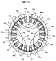
図5において、U3a、U1a、U2bを3直列巻線とし、同様にV5a、V3a、V4bとW6a、W4a、W5bを3直列巻線として、これらをタイプaの3直列巻線とする。また、U6b、U4b、U5aを3直列巻線とし、同様にV2b、V6b、V1aとW3b、W1b、W2aを3直列巻線として、これらをタイプbの3直列巻線とする。
In FIG. 5, U3a, U1a, U2b are three series windings, and similarly V5a, V3a, V4b and W6a, W4a, W5b are three series windings, and these are three series windings of type a. Also, U6b, U4b, U5a are three series windings, and similarly V2b, V6b, V1a and W3b, W1b, W2a are three series windings, which are type b three series windings.
前記の各3直列巻線において、3直列の巻線の巻回数を、この順に、半整数Na、整数N、半整数Nbとする。このとき、組A:U1a、W1b、V3a、U4b、W4a、V6bの巻回数は整数Nであり、組B:V1a、U2b、W2a、V4b、U5a、W5bの巻回数は半整数Nbであり、組C:V2b、 U3a、 W3b、 V5a、 U6b、 W6aの巻回数は、半整数Naであり、各組の中では同じ巻回数になる。
In each of the three series windings described above, the number of turns of the three series windings is, in this order, half integer Na, integer N, and half integer Nb. At this time, the number of turns of the set A: U1a, W1b, V3a, U4b, W4a, V6b is an integer N, and the number of turns of the set B: V1a, U2b, W2a, V4b, U5a, W5b is a half integer Nb, Set C: The number of turns of V2b, U3a, W3b, V5a, U6b, and W6a is a half integer Na, and the number of turns is the same in each set.
前記のように、3直列巻線と巻回数を構成した時に、ティースT1からT18をこの順に並べて巻回した時の、各巻線の接続と口出し線及び渡り線の配置を、図5を用いて説明する。
As described above, when three series windings and the number of turns are configured, the connections of the windings and the arrangement of lead wires and connecting wires when the teeth T1 to T18 are wound in this order are shown in FIG. explain.
ここで、巻線の口出し線に、U、V、Wの各相と、a、bの巻線タイプと、電流方向の順逆(a、b)を1文字ずつ用いて記号を付けて区別する。例えば、口出し線Vaaに接続される巻線V5aは、半整数Na回の巻回数のため、渡り線はVaaと逆側になって巻線V3aに渡り、V3aは整数N回の巻回数のため、渡り線はVaaと逆側になって巻線V4bに渡り、V4bは半整数Nb回の巻回数のため、口出し線VabはVaaと同じ側になる。
Here, the lead wires of the winding are distinguished from each other by using symbols for U, V and W phases, a and b winding types, and forward and reverse current directions (a and b) one by one. . For example, the winding V5a connected to the lead wire Vaa has a half-integer number of Na turns, the connecting wire is on the opposite side of Vaa and crosses the winding V3a, and V3a has an integer N turns The crossover wire is opposite to Vaa and crosses over the winding V4b. Since V4b is a half-integer Nb number of turns, the lead wire Vab is on the same side as Vaa.
このように、前記の3直列巻線と巻回数を用いることにより、口出し線と、隣接より遠くのティースへの渡り線を逆側に配置できる。
Thus, by using the above-described three series windings and the number of turns, the lead wire and the connecting wire to the teeth farther from the adjacent can be arranged on the opposite side.
以下では、分割された固定子コアのティースに巻回して3直列巻線を作成しておき、固定子に組みたてる手順の例を、図6(A)と図6(B)を用いて説明する。
In the following, an example of a procedure for creating three series windings by winding the teeth of the divided stator core and assembling the stators with reference to FIGS. 6 (A) and 6 (B) will be described. explain.
図6(A)と図6(B)は、口出し線を下にして、分割コアを挿入して組み立てていく例での、渡り線側(上側)から見た巻線端部の正面図であり、挿入された分割コア巻線と渡り線の配置が示されている。
6 (A) and 6 (B) are front views of the winding end portion as viewed from the crossover side (upper side) in an example in which the split core is inserted and assembled with the lead wire down. Yes, the arrangement of the inserted split core windings and crossovers is shown.
最初に、タイプaの3直列巻線をU相、V相、W相の順に組み立てるとする。第1に、U3a、U1a、U2bの3直列巻線を含む分割コアを配置し、第2に、V5a、V3a、V4bの3直列巻線を含む分割コアを配置し、第3に、W6a、W4a、W5bの3直列巻線を含む分割コアを配置していく。このとき、図6(A)に示すように、分割コアは干渉することなく、配置することができる。図6(A)は、この時点での配置を示している。
First, suppose that type 3 series windings are assembled in the order of U phase, V phase, and W phase. First, a split core including three series windings of U3a, U1a, and U2b is arranged. Second, a split core including three series windings of V5a, V3a, and V4b is arranged. Third, W6a, Split cores including three series windings of W4a and W5b will be arranged. At this time, as shown in FIG. 6A, the split cores can be arranged without interference. FIG. 6A shows the arrangement at this point.
次に、タイプaの渡り線511ないし516をすべて内径側に変形させておき、タイプbの3直列巻線をU相、V相、W相の順に組み立てる手順の例を、図6(B)を用いて説明する。
第4に、U6b、U4b、U5aの3直列巻線含む分割コアを配置し、第5に、V2b、V6b、V1aの3直列巻線を含む分割コアを配置し、第6に、W3b、W1b、W2aの3直列巻線を含む分割コアを配置していく。このとき、図6(A)の場合と同様に、各3直列巻線の渡り線と、分割コアは干渉することなく、全ての分割コアを配置することができる。 Next, the type acrossover wires 511 to 516 are all deformed to the inner diameter side, and an example of a procedure for assembling the type b three series windings in the order of the U phase, the V phase, and the W phase is shown in FIG. Will be described.
Fourth, a split core including three series windings of U6b, U4b, and U5a is arranged, fifth, a split core including three series windings of V2b, V6b, and V1a is arranged, and sixth, W3b, W1b , Split cores including 3 series windings of W2a will be arranged. At this time, as in the case of FIG. 6A, all the split cores can be arranged without interference between the connecting wires of the three series windings and the split cores.
第4に、U6b、U4b、U5aの3直列巻線含む分割コアを配置し、第5に、V2b、V6b、V1aの3直列巻線を含む分割コアを配置し、第6に、W3b、W1b、W2aの3直列巻線を含む分割コアを配置していく。このとき、図6(A)の場合と同様に、各3直列巻線の渡り線と、分割コアは干渉することなく、全ての分割コアを配置することができる。 Next, the type a
Fourth, a split core including three series windings of U6b, U4b, and U5a is arranged, fifth, a split core including three series windings of V2b, V6b, and V1a is arranged, and sixth, W3b, W1b , Split cores including 3 series windings of W2a will be arranged. At this time, as in the case of FIG. 6A, all the split cores can be arranged without interference between the connecting wires of the three series windings and the split cores.
図6(B)は、この時点での配置を示している。前記のようにして、全ての分割コアを配置した後に、内径側に変形させたタイプaの6本の渡り線を巻線端部に配置し、固定子巻線の組立てが完了する。第2例は、変形させて巻線端部に配置する渡り線が6本である。
このような配置にすると、口出し線側は、Y結線での中性点と電源端子への接続か、Δ結線での電源端子への接続を実施すればよく、渡り線の処理が不要になるため、追加部材や複雑な処理手順を用いる必要がなくなるため、作業効率を向上し、製造コストを低減できる。 FIG. 6B shows the arrangement at this point. As described above, after all the split cores are arranged, six crossover wires of type a deformed to the inner diameter side are arranged at the winding end, and the assembly of the stator winding is completed. In the second example, there are six connecting wires that are deformed and arranged at the winding end.
With this arrangement, the lead wire side only needs to be connected to the neutral point and the power supply terminal in the Y connection, or connected to the power supply terminal in the Δ connection, and the processing of the crossover line becomes unnecessary. Therefore, it is not necessary to use an additional member or a complicated processing procedure, so that work efficiency can be improved and manufacturing cost can be reduced.
(第3の実施形態)
図7と図8を用いて、本発明の第3の実施形態による永久磁石式14極18スロットブラシレスモータの構成を説明する。 (Third embodiment)
The configuration of a permanent magnet type 14-pole 18-slot brushless motor according to a third embodiment of the present invention will be described with reference to FIGS.
図7と図8を用いて、本発明の第3の実施形態による永久磁石式14極18スロットブラシレスモータの構成を説明する。 (Third embodiment)
The configuration of a permanent magnet type 14-pole 18-slot brushless motor according to a third embodiment of the present invention will be described with reference to FIGS.
図7において、U3a、U2b、U1aを3直列巻線とし、同様にV5a、V4b、V3aとW6a、W5b、W4aを3直列巻線として、これらをタイプaの3直列巻線とする。また、U6b、U5a、U4bを3直列巻線とし、同様にV2b、V1a、V6bとW3b、W2a、W1bを3直列巻線として、これらをタイプbの3直列巻線とする。
In FIG. 7, U3a, U2b, U1a are three series windings, and V5a, V4b, V3a and W6a, W5b, W4a are three series windings, and these are type a three series windings. U6b, U5a, U4b are three series windings. Similarly, V2b, V1a, V6b and W3b, W2a, W1b are three series windings, and these are three series windings of type b.
前記の各3直列巻線において、3直列の巻線の巻回数を、この順に、整数N、半整数Na、半整数Nbとする。このとき、組A:U1a、W1b、V3a、U4b、W4a、V6bの巻回数は、半整数Nbであり、組B:V1a、U2b、W2a、V4b、U5a、W5bの巻回数は、半整数Naであり、組C:V2b、U3a、W3b、V5a、U6b、W6aの巻回数は、整数Nであり、各組の中では同じ巻回数になる。
In each of the three series windings described above, the number of turns of the three series windings is assumed to be an integer N, a half integer Na, and a half integer Nb in this order. At this time, the number of turns of the set A: U1a, W1b, V3a, U4b, W4a, V6b is a half integer Nb, and the set B: the number of turns of the V1a, U2b, W2a, V4b, U5a, W5b is a half integer Na The number of turns of the group C: V2b, U3a, W3b, V5a, U6b, W6a is an integer N, and the number of turns is the same in each group.
前記のように、3直列巻線と巻回数を構成した時に、ティースT1からT18をこの順に並べて巻回した時の、各巻線の接続と口出し線及び渡り線の配置を、図7を用いて説明する。ここで、巻線の口出し線に、U、V、Wの各相と、a、bの巻線タイプと、電流方向の順逆(a、b)を1文字ずつ用いて記号を付けて、区別する。
As described above, when the three series windings and the number of turns are configured, the connections of the windings and the arrangement of the lead wires and the connecting wires when the teeth T1 to T18 are wound in this order are shown in FIG. explain. Here, the lead wire of the winding is distinguished by attaching a symbol using U, V, W phases, a, b winding type, and forward / reverse current direction (a, b) one character at a time. To do.
例えば、口出し線Vaaに接続される巻線V5aは、整数N回の巻回数のため、渡り線はVaaと同じ側になって隣接する巻線V4bに渡り、V4bは半整数Na回の巻回数のため、渡り線はVaaと逆側になって巻線V3aに渡り、V3aは半整数Nb回の巻回数のため、口出し線VabはVaaと同じ側になる。このとき、 V4bの巻回方向は、V5a、 V3aとは逆方向になっている。
For example, the winding V5a connected to the lead wire Vaa is an integer N turns, so the connecting wire is on the same side as Vaa and goes to the adjacent winding V4b, and V4b is a half integer Na turns Therefore, the crossover line is opposite to Vaa and crosses over the winding V3a. Since V3a is a half-integer Nb number of turns, the lead wire Vab is on the same side as Vaa. At this time, the winding direction of V4b is opposite to V5a and V3a.
このように、前記の3直列巻線と巻回数を用いることにより、口出し線と、隣接より遠くのティースへの渡り線を逆側に配置できる。
Thus, by using the above-described three series windings and the number of turns, the lead wire and the connecting wire to the teeth farther from the adjacent can be arranged on the opposite side.
以下では、分割された固定子コアのティースに巻回して3直列巻線を作成しておき、固定子に組みたてる手順の例を、図8を用いて説明する。図8は、口出し線を下にして、分割コアを挿入して組み立てていく例での、渡り線側(上側)から見た巻線端部の正面図であり、挿入された分割コア巻線と渡り線の配置が示されている。
Hereinafter, an example of a procedure in which three series windings are created by winding the teeth of the divided stator core and assembled to the stator will be described with reference to FIG. FIG. 8 is a front view of the winding end as viewed from the connecting wire side (upper side) in an example in which the split core is inserted and assembled with the lead wire down, and the inserted split core winding The crossover arrangement is shown.
最初に、タイプaの3直列巻線をU相、V相、W相の順に組み立てることは、図6(A)の場合と同様に、各3直列巻線の渡り線と、分割コアが干渉することなく、配置することができるので、説明を省略する。
First, assembling the 3 series windings of type a in the order of the U phase, V phase, and W phase is the same as the case of FIG. Since it can arrange | position without doing, description is abbreviate | omitted.
なお、隣接する巻線への渡り線の場合は、間に他のティースが挿入されることはないので、干渉は生じない。このため、口出し線と同じ側に配置されても問題はない。本例では、口出し線と逆側になる渡り線は6本である。
In addition, in the case of a jumper to adjacent windings, no other teeth are inserted between them, so no interference occurs. For this reason, there is no problem even if it is arranged on the same side as the lead wire. In this example, there are six connecting wires on the opposite side to the lead wire.
次に、タイプaの渡り線521、522、523の3本をすべて内径側に変形させておき、タイプbの3直列巻線をU相、V相、W相の順に組み立てる手順の例を、図8を用いて説明する。
第4に、U6b、U5a、U4bの3直列巻線含む分割コアを配置し、第5に、V2b、V1a、V6bの3直列巻線を含む分割コアを配置し、第6に、W3b、W2a、W1bの3直列巻線を含む分割コアを配置していく。このとき、図6(A)の場合と同様に、各3直列巻線の渡り線と、分割コアは干渉することなく、全ての分割コアを配置することができる。図8は、この時点での配置を示している。 Next, the type a crossover wires 521, 522, and 523 are all deformed to the inside diameter side, and an example of the procedure for assembling the type b three series windings in the order of U phase, V phase, and W phase. This will be described with reference to FIG.
Fourth, a split core including three series windings of U6b, U5a, and U4b is arranged, fifth, a split core including three series windings of V2b, V1a, and V6b is arranged, and sixth, W3b, W2a , Split cores including three W1b series windings are arranged. At this time, as in the case of FIG. 6A, all the split cores can be arranged without interference between the connecting wires of the three series windings and the split cores. FIG. 8 shows the arrangement at this point.
第4に、U6b、U5a、U4bの3直列巻線含む分割コアを配置し、第5に、V2b、V1a、V6bの3直列巻線を含む分割コアを配置し、第6に、W3b、W2a、W1bの3直列巻線を含む分割コアを配置していく。このとき、図6(A)の場合と同様に、各3直列巻線の渡り線と、分割コアは干渉することなく、全ての分割コアを配置することができる。図8は、この時点での配置を示している。 Next, the type a
Fourth, a split core including three series windings of U6b, U5a, and U4b is arranged, fifth, a split core including three series windings of V2b, V1a, and V6b is arranged, and sixth, W3b, W2a , Split cores including three W1b series windings are arranged. At this time, as in the case of FIG. 6A, all the split cores can be arranged without interference between the connecting wires of the three series windings and the split cores. FIG. 8 shows the arrangement at this point.
前記のようにして、全ての分割コアを配置した後に、内径側に変形させたタイプaの3本の渡り線を巻線端部に配置し、固定子巻線の組立てが完了する。第3例は、変形させて巻線端部に配置する渡り線が3本であるため、作業効率が高い。また、第1例と第2例に比べて、渡り線の長さがほぼ半減するため、巻線抵抗が改善する。
As described above, after all the split cores are arranged, three crossover wires of type a deformed to the inner diameter side are arranged at the winding end, and the assembly of the stator winding is completed. In the third example, since there are three connecting wires that are deformed and arranged at the winding end, the working efficiency is high. Further, since the length of the jumper wire is almost halved compared to the first example and the second example, the winding resistance is improved.
このような配置にすると、口出し線側は、Y結線での中性点と電源端子への接続か、Δ結線での電源端子への接続を実施すればよく、渡り線の処理が不要になるため、追加部材や複雑な処理手順を用いる必要がなくなるため、作業効率を向上し、製造コストを低減できる。
With this arrangement, the lead wire side only needs to be connected to the neutral point and the power supply terminal in the Y connection, or connected to the power supply terminal in the Δ connection, and the processing of the crossover line becomes unnecessary. Therefore, it is not necessary to use an additional member or a complicated processing procedure, so that work efficiency can be improved and manufacturing cost can be reduced.
(第4の実施形態)
図9と図10を用いて、本発明の第4の実施形態による永久磁石式14極18スロットブラシレスモータの構成を説明する。 (Fourth embodiment)
The configuration of a permanent magnet type 14-pole 18-slot brushless motor according to a fourth embodiment of the present invention will be described with reference to FIGS.
図9と図10を用いて、本発明の第4の実施形態による永久磁石式14極18スロットブラシレスモータの構成を説明する。 (Fourth embodiment)
The configuration of a permanent magnet type 14-pole 18-slot brushless motor according to a fourth embodiment of the present invention will be described with reference to FIGS.
図1において、U3a、U2b、U1aを3直列巻線とし、同様にV5a、V4b、V3aとW6a、W5b、W4aを3直列巻線として、これらをタイプaの3直列巻線とする。また、U6b、U5a、U4bを3直列巻線とし、同様にV2b、V1a、V6bとW3b、W2a、W1bを3直列巻線として、これらをタイプbの3直列巻線とする。前記の各3直列巻線において、3直列の巻線の巻回数を、この順に、半整数Na、整数N、半整数Nbとする。このとき、組A:U1a、W1b、V3a、U4b、W4a、V6bの巻回数は、半整数Nbであり、組B:V1a、U2b、W2a、V4b、U5a、W5bの巻回数は、整数Nであり、組C:V2b、U3a、W3b、V5a、U6b、W6aの巻回数は、半整数Naであり、各組の中では同じ巻回数になる。
In FIG. 1, U3a, U2b, U1a are three series windings, and similarly V5a, V4b, V3a and W6a, W5b, W4a are three series windings, and these are three series windings of type a. U6b, U5a, U4b are three series windings. Similarly, V2b, V1a, V6b and W3b, W2a, W1b are three series windings, and these are three series windings of type b. In each of the three series windings, the number of turns of the three series windings is set to a half integer Na, an integer N, and a half integer Nb in this order. At this time, the number of turns of set A: U1a, W1b, V3a, U4b, W4a, V6b is a half integer Nb, and the number of turns of set B: V1a, U2b, W2a, V4b, U5a, W5b is an integer N Yes, set C: The number of turns of V2b, U3a, W3b, V5a, U6b, W6a is a half integer Na, and the number of turns is the same in each set.
前記のように、3直列巻線と巻回数を構成した時に、ティースT1からT18をこの順に並べて巻回した時の、各巻線の接続と口出し線及び渡り線の配置を、図9を用いて説明する。ここで、巻線の口出し線に、U、V、Wの各相と、a、bの巻線タイプと、電流方向の順逆(a、b)を1文字ずつ用いて記号を付けて、区別する。
As described above, when the three series windings and the number of turns are configured, the connections of the windings and the arrangement of the lead wires and the connecting wires when the teeth T1 to T18 are wound in this order are shown in FIG. explain. Here, the lead wire of the winding is distinguished by attaching a symbol using U, V, W phases, a, b winding type, and forward / reverse current direction (a, b) one character at a time. To do.
例えば、口出し線Vaaに接続される巻線V5aは、半整数Na回の巻回数のため、渡り線はVaaと逆側になって隣接する巻線V4bに渡り、V4bは整数N回の巻回数のため、渡り線はVaaと逆側になって巻線V3aに渡り、V3aは半整数Nb回の巻回数のため、口出し線VabはVaaと同じ側になる。このとき、V4bの巻回方向は、V5a、V3aとは逆方向になっている。
For example, the winding V5a connected to the lead wire Vaa has a half-integer number of Na turns, so the connecting wire is opposite to Vaa and goes to the adjacent winding V4b, and V4b is an integer N turns Therefore, the crossover line is opposite to Vaa and crosses over the winding V3a. Since V3a is a half-integer Nb number of turns, the lead wire Vab is on the same side as Vaa. At this time, the winding direction of V4b is opposite to V5a and V3a.
このように、前記の3直列巻線と巻回数を用いることにより、口出し線と、隣接より遠くのティースへの渡り線を逆側に配置できる。
Thus, by using the above-described three series windings and the number of turns, the lead wire and the connecting wire to the teeth farther from the adjacent can be arranged on the opposite side.
以下では、分割された固定子コアのティースに巻回して3直列巻線を作成しておき、固定子に組みたてる手順の例を、図10を用いて説明する。図10は、口出し線を下にして、分割コアを挿入して組み立てていく例での、渡り線側(上側)から見た巻線端部の正面図であり、挿入された分割コア巻線と渡り線の配置が示されている。
Hereinafter, an example of a procedure in which three series windings are created by winding the teeth of the divided stator core and assembled to the stator will be described with reference to FIG. FIG. 10 is a front view of the winding end as viewed from the crossover side (upper side) in an example in which the split core is inserted and assembled with the lead wire down, and the inserted split core winding The crossover arrangement is shown.
最初に、タイプaの3直列巻線をU相、V相、W相の順に組み立てることは、図6(A)の場合と同様に、各3直列巻線の渡り線と、分割コアが干渉することなく、配置することができるので、説明を省略する。
First, assembling the 3 series windings of type a in the order of the U phase, V phase, and W phase is the same as the case of FIG. Since it can arrange | position without doing, description is abbreviate | omitted.
なお、隣接する巻線への渡り線の場合は、間に他のティースが挿入されることはないので、干渉は生じない。本例では、口出し線と逆側になる渡り線は、隣接する巻線への渡り線が6本、隣接より遠くの巻線への渡り線が6本である。
In addition, in the case of a jumper to adjacent windings, no other teeth are inserted between them, so no interference occurs. In this example, the connecting wires on the opposite side to the lead wire have six connecting wires to adjacent windings and six connecting wires to windings farther from the adjacent wires.
次に、タイプaの渡り線531、532、533の3本をすべて内径側に変形させておき、タイプbの3直列巻線をU相、V相、W相の順に組み立てる手順の例を、図10を用いて説明する。
Next, all three type a crossover wires 531, 532, and 533 are deformed to the inner diameter side, and an example of the procedure for assembling the three series windings of type b in the order of U phase, V phase, and W phase. This will be described with reference to FIG.
第4に、U6b、U5a、U4bの3直列巻線含む分割コアを配置し、第5に、V2b、V1a、V6bの3直列巻線を含む分割コアを配置し、第6に、W3b、W2a、W1bの3直列巻線を含む分割コアを配置していく。このとき、図6(A)の場合と同様に、各3直列巻線の渡り線と、分割コアは干渉することなく、全ての分割コアを配置することができる。図10は、この時点での配置を示している。
Fourth, a split core including three series windings of U6b, U5a, and U4b is arranged, fifth, a split core including three series windings of V2b, V1a, and V6b is arranged, and sixth, W3b, W2a , Split cores including three W1b series windings are arranged. At this time, as in the case of FIG. 6A, all the split cores can be arranged without interference between the connecting wires of the three series windings and the split cores. FIG. 10 shows the arrangement at this point.
前記のようにして、全ての分割コアを配置した後に、内径側に変形させたタイプaの3本の渡り線531、532、533を巻線端部に配置し、固定子巻線の組立てが完了する。第4例は、変形させて巻線端部に配置する渡り線が3本であるため、作業効率が高い。また、第1例と第2例に比べて、渡り線の長さがほぼ半減するため、巻線抵抗が改善する。
As described above, after all the split cores are arranged, three crossover wires 531 532 533 of type a deformed to the inner diameter side are arranged at the winding ends, and the stator winding is assembled. Complete. In the fourth example, since there are three connecting wires that are deformed and arranged at the winding end, the working efficiency is high. Further, since the length of the jumper wire is almost halved compared to the first example and the second example, the winding resistance is improved.
このような配置にすると、口出し線側は、Y結線での中性点と電源端子への接続か、Δ結線での電源端子への接続を実施すればよく、渡り線の処理が不要になるため、追加部材や複雑な処理手順を用いる必要がなくなるため、作業効率を向上し、製造コストを低減できる。
With this arrangement, the lead wire side only needs to be connected to the neutral point and the power supply terminal in the Y connection, or connected to the power supply terminal in the Δ connection, and the processing of the crossover line becomes unnecessary. Therefore, it is not necessary to use an additional member or a complicated processing procedure, so that work efficiency can be improved and manufacturing cost can be reduced.
本発明の第4の実施形態において、半整数Nb=8.5、整数N=6、半整数Nba=6.5としたときに、永久磁石式14極18スロットブラシレスモータのトルクとトルクリップルに関して、計算機シミュレーションを実施して、半整数Nb=整数N=半整数Nba=7の時のトルクとトルクリップルに対して比較した。半整数Nb=8.5、整数N=6、半整数Nba=6.5の異数巻でのトルク値の同数巻に対する比を、電流値を横軸にして、図11に示す。異数巻の方が0.4~0.5%、トルク値が増加する結果となったが、平均巻数が同じであれば、トルク値はほぼ同じになるという結果が得られた。
In the fourth embodiment of the present invention, when the half integer Nb = 8.5, the integer N = 6, and the half integer Nba = 6.5, the torque and torque ripple of the permanent magnet type 14-pole 18-slot brushless motor Then, a computer simulation was performed to compare the torque and torque ripple when half integer Nb = integer N = half integer Nba = 7. FIG. 11 shows the ratio of the torque value of the different number of turns of half integer Nb = 8.5, integer N = 6, half integer Nba = 6.5 to the same number of turns, with the current value as the horizontal axis. The result was that the torque value increased by 0.4 to 0.5% for the different number of turns, but the torque value was almost the same if the average number of turns was the same.
また、異数巻と同数巻のトルクリップルの計算値を、電流値を横軸にしたグラフで図12に示す。電流が小さい時は、異数巻と同数巻のトルクリップルはほぼ等しく、電流値が大きくなっても、1%以下の値となった。また、異数巻と同数巻のトルクリップル計算値の最大値がほぼ等しかった。
Also, the calculated values of torque ripples for the same number of turns and the same number of turns are shown in FIG. When the current was small, the torque ripples of the same number of turns and the same number of turns were almost equal, and even when the current value was large, the value was 1% or less. Moreover, the maximum value of the calculated torque ripple of the same number of turns as the number of different turns was almost equal.
この結果から、本発明で実施したような、組A、組B、組Cの巻回数が違うモータであっても、各組内で巻回数が同じであれば、このモータのトルクリップルは、全ての巻回数が前記モータの平均巻回数のモータのトルクリップルと同程度になり、また、トルクは、全ての巻回数が同じ平均巻回数のモータのトルクとほぼ一致することが裏付けられたと考えられる。これにより、半発明は、モータの特性を損なうことなく、製造の作業効率を向上できる効果を持つと考えられる。
From this result, even if the number of windings of the group A, group B, and group C is different as in the present invention, if the number of windings is the same in each group, the torque ripple of this motor is It is thought that it was confirmed that the number of turns was almost the same as the torque ripple of the motor with the average number of turns of the motor, and that the torque was almost the same as the torque of the motor with the same number of turns. It is done. Thereby, it is considered that the semi-invention has an effect of improving the manufacturing work efficiency without impairing the characteristics of the motor.
100…固定子、101…固定子コア、110…コアバック、120…分割固定子コアの嵌合部、T1ないしT18…ティース、U1a、V1a、V2b、W1b、U2b、U3a、V3a、W2a、W3b、U4b、V4b、V5a、W4a、U5a、U6b、V6b、W5b、W6a…固定子巻線、200…回転子、201…回転子コア、210…永久磁石、301ないし303…中性点、351ないし359…端子、501ないし506…渡り線、511ないし516…渡り線、521ないし523…渡り線、531ないし533…渡り線
100 ... Stator, 101 ... Stator core, 110 ... Core back, 120 ... Split stator core fitting, T1 to T18 ... Teeth, U1a, V1a, V2b, W1b, U2b, U3a, V3a, W2a, W3b , U4b, V4b, V5a, W4a, U5a, U6b, V6b, W5b, W6a ... stator winding, 200 ... rotor, 201 ... rotor core, 210 ... permanent magnet, 301 thru 303 ... neutral point, 351 thru 359 ... terminal, 501 to 506 ... crossover, 511 to 516 ... crossover, 521 to 523 ... crossover, 531 to 533 ... crossover
Claims (4)
- 集中巻固定子と永久磁石式回転子を備えるブラシレスモータにおいて、
直列に巻回されるティースの数が3以上であり、
口出し線に接続されるティースの巻線に隣接して接続される巻線がある場合はそれらの合計巻回数を端巻回数とし、
あるいは、前記口出し線に接続されるティースの巻線に隣接して接続される巻線がない場合は前記口出し線に接続されるティースの巻線の巻回数を端巻回数とし、
前記口出し線に接続されるティースの巻線あるいは隣接して接続される巻線から隣接より遠くのティースの巻線と渡り線で接続されて、別の口出し線に接続されるティースの巻線あるいは隣接して接続される巻線ではないティースの巻線の巻回数を中巻回数とし、
あるいは、前記の渡り線で接続された隣接より遠くのティースの巻線に隣接して接続される巻線がある場合はそれらの合計巻回数を中巻回数とし、あるいは、前記の渡り線で接続された隣接より遠くのティースの巻線が存在しない場合は中巻回数を0とするとき、
前記端巻回数が半整数であり、前記中巻回数が整数であるように、巻回された固定子巻線で構成されるブラシレスモータ。 In a brushless motor comprising a concentrated winding stator and a permanent magnet rotor,
The number of teeth wound in series is 3 or more,
If there is a winding connected adjacent to the winding of the teeth connected to the lead wire, the total number of turns is the number of end turns,
Alternatively, if there is no winding connected adjacent to the winding of the teeth connected to the lead wire, the number of turns of the winding of the tooth connected to the lead wire is the number of end turns,
The winding of the tooth connected to the lead wire, or the winding of the tooth connected to the other winding wire connected to the winding of the tooth farther from the adjacent winding from the winding connected to the lead wire, or The number of windings of the teeth that are not adjacently connected is the number of turns of the middle winding,
Alternatively, if there are windings connected adjacent to the windings of teeth farther than the adjacent ones connected by the connecting wires, the total number of turns is set to the number of intermediate turns, or connected by the connecting wires If there are no teeth windings farther than the adjacent ones,
A brushless motor comprising stator windings wound so that the number of end turns is a half integer and the number of intermediate turns is an integer. - 請求項1に記載のブラシレスモータであって、
前記口出し線に接続されるティースの巻線の巻回数を半整数とし、
前記別の口出し線に接続されるティースの巻線の巻回数を半整数とし、
前記口出し線に接続されるティースの巻線とは渡り線で隣接より遠くに接続されており、
前記別の口出し線に接続されるティースの巻線とも渡り線で隣接より遠くに接続されているティースの巻線の巻回数を整数とするように巻回された固定子巻線で構成される、14極18スロットまたは22極18スロットまたはその倍数の極スロット組合せの、集中巻固定子と永久磁石式回転子を備えるブラシレスモータ。 The brushless motor according to claim 1,
The winding number of the winding of the teeth connected to the lead wire is a half integer,
The winding number of the winding of the teeth connected to the other lead wire is a half integer,
The winding of the teeth connected to the lead wire is connected to the farther than the adjacent by a crossover wire,
The teeth winding connected to the other lead wire is also composed of a stator winding wound so that the number of turns of the teeth winding connected farther than the adjacent by a crossover is an integer. A brushless motor comprising a concentrated winding stator and a permanent magnet rotor of a 14-pole 18-slot or 22-pole 18-slot or multiple pole slot combination. - 請求項1に記載のブラシレスモータであって、
前記口出し線に接続されるティースの巻線とそれに隣接して接続される巻線の合計巻回数を半整数とし、
前記口出し線に接続されるティースの巻線に隣接して接続される巻線から渡り線で隣接より遠くに接続され、
前記別の口出し線に接続されるティースの巻線の巻回数を半整数とするように巻回された固定子巻線で構成される、14極18スロットまたは22極18スロットまたはその倍数の極スロット組合せの、集中巻固定子と永久磁石式回転子を備えるブラシレスモータ。 The brushless motor according to claim 1,
The total number of turns of the winding of the teeth connected to the lead wire and the winding connected adjacent thereto is a half integer,
Connected farther from the adjacent winding wire from the winding connected adjacent to the tooth winding connected to the lead wire,
14 poles 18 slots or 22 poles 18 slots or multiples of the poles formed by winding the windings of the teeth connected to the other lead wire to a half integer A brushless motor comprising a concentrated winding stator and a permanent magnet rotor in a slot combination. - 請求項1ないし3に記載のいずれかのブラシレスモータであって、
電動パワーステアリング又は電動ブレーキの自動車補機に用いられるブラシレスモータ。 The brushless motor according to any one of claims 1 to 3,
A brushless motor used in electric power steering or electric brake automotive accessories.
Priority Applications (3)
| Application Number | Priority Date | Filing Date | Title |
|---|---|---|---|
| EP17789149.6A EP3451505A4 (en) | 2016-04-28 | 2017-03-27 | Rotary electric machine |
| US16/094,004 US20190131840A1 (en) | 2016-04-28 | 2017-03-27 | Rotary Electric Machine |
| CN201780025692.7A CN109075638B (en) | 2016-04-28 | 2017-03-27 | Rotating electrical machine |
Applications Claiming Priority (2)
| Application Number | Priority Date | Filing Date | Title |
|---|---|---|---|
| JP2016090040A JP6650336B2 (en) | 2016-04-28 | 2016-04-28 | Rotating electric machine |
| JP2016-090040 | 2016-04-28 |
Publications (1)
| Publication Number | Publication Date |
|---|---|
| WO2017187860A1 true WO2017187860A1 (en) | 2017-11-02 |
Family
ID=60160340
Family Applications (1)
| Application Number | Title | Priority Date | Filing Date |
|---|---|---|---|
| PCT/JP2017/012217 WO2017187860A1 (en) | 2016-04-28 | 2017-03-27 | Rotary electric machine |
Country Status (5)
| Country | Link |
|---|---|
| US (1) | US20190131840A1 (en) |
| EP (1) | EP3451505A4 (en) |
| JP (1) | JP6650336B2 (en) |
| CN (1) | CN109075638B (en) |
| WO (1) | WO2017187860A1 (en) |
Families Citing this family (3)
| Publication number | Priority date | Publication date | Assignee | Title |
|---|---|---|---|---|
| JP6912508B2 (en) * | 2019-03-19 | 2021-08-04 | ファナック株式会社 | Stator and motor |
| JP6727457B1 (en) * | 2019-03-27 | 2020-07-22 | 三菱電機株式会社 | Stator and electric motor |
| EP4270745A4 (en) * | 2020-12-23 | 2024-02-28 | Mitsubishi Electric Corp | Permanent magnet-type rotary electric machine |
Citations (2)
| Publication number | Priority date | Publication date | Assignee | Title |
|---|---|---|---|---|
| WO2013136646A1 (en) * | 2012-03-13 | 2013-09-19 | パナソニック株式会社 | Motor and method for manufacturing stator therefor |
| JP2016052224A (en) * | 2014-09-02 | 2016-04-11 | アイシン精機株式会社 | Stator, rotary electric machine applying stator thereto, and connection method for stator |
Family Cites Families (10)
| Publication number | Priority date | Publication date | Assignee | Title |
|---|---|---|---|---|
| US6472790B2 (en) * | 2000-02-24 | 2002-10-29 | Briggs & Stratton Corporation | Stator for an electric motor/generator with a half-integer winding |
| JP2009213257A (en) * | 2008-03-04 | 2009-09-17 | Hitachi Ltd | Rotating electric machine |
| US8072112B2 (en) * | 2008-06-16 | 2011-12-06 | Asmo Co., Ltd. | Motor, stator, and method for manufacturing stator |
| DE112009004498T5 (en) * | 2009-03-11 | 2012-08-02 | Hitachi, Ltd. | Alternator for a vehicle |
| JP5510703B2 (en) * | 2009-08-21 | 2014-06-04 | 株式会社デンソー | Rotating electric machine and control system thereof |
| CN102468731B (en) * | 2010-11-15 | 2014-06-11 | 京能新能源科技(上海)有限公司 | Stator of permanent-magnet synchronous motor |
| CN102142723A (en) * | 2010-11-22 | 2011-08-03 | 常州市裕成富通电机有限公司 | Motor stator used for electrombile and half-turn winding method of motor stator winding |
| DE102011078157A1 (en) * | 2011-06-28 | 2013-01-03 | Robert Bosch Gmbh | Electric machine e.g. brushless electric machine, for use in electrical power steering apparatus, has coil whose windings are wound around rotor poles, where one of coils in coil group has number of turns smaller than that of other coils |
| JP2013118750A (en) * | 2011-12-02 | 2013-06-13 | Hitachi Ltd | Axial gap type rotary electric machine and manufacturing method thereof |
| TWI551008B (en) * | 2015-01-27 | 2016-09-21 | 建準電機工業股份有限公司 | Motor winding assembly |
-
2016
- 2016-04-28 JP JP2016090040A patent/JP6650336B2/en not_active Expired - Fee Related
-
2017
- 2017-03-27 US US16/094,004 patent/US20190131840A1/en not_active Abandoned
- 2017-03-27 EP EP17789149.6A patent/EP3451505A4/en not_active Withdrawn
- 2017-03-27 CN CN201780025692.7A patent/CN109075638B/en not_active Expired - Fee Related
- 2017-03-27 WO PCT/JP2017/012217 patent/WO2017187860A1/en active Application Filing
Patent Citations (2)
| Publication number | Priority date | Publication date | Assignee | Title |
|---|---|---|---|---|
| WO2013136646A1 (en) * | 2012-03-13 | 2013-09-19 | パナソニック株式会社 | Motor and method for manufacturing stator therefor |
| JP2016052224A (en) * | 2014-09-02 | 2016-04-11 | アイシン精機株式会社 | Stator, rotary electric machine applying stator thereto, and connection method for stator |
Non-Patent Citations (1)
| Title |
|---|
| See also references of EP3451505A4 * |
Also Published As
| Publication number | Publication date |
|---|---|
| CN109075638A (en) | 2018-12-21 |
| CN109075638B (en) | 2020-11-10 |
| EP3451505A1 (en) | 2019-03-06 |
| US20190131840A1 (en) | 2019-05-02 |
| JP6650336B2 (en) | 2020-02-19 |
| JP2017200335A (en) | 2017-11-02 |
| EP3451505A4 (en) | 2019-12-25 |
Similar Documents
| Publication | Publication Date | Title |
|---|---|---|
| US9520753B2 (en) | Stator assembly with winding sets having hairpins from multiple hairpin layers | |
| JP5944066B2 (en) | PERMANENT MAGNET MOTOR, DRIVE DEVICE INTEGRATED PERMANENT MAGNET MOTOR AND MANUFACTURING METHOD FOR PERMANENT MAGNET MOTOR | |
| US20180248432A1 (en) | Rotary electric machine | |
| JP6307324B2 (en) | Brushless motor and electric power steering apparatus using the same | |
| JP5028220B2 (en) | Electric power steering motor, electromagnetic shield structure and electromagnetic shield method used therefor | |
| JP6257212B2 (en) | Brushless motor | |
| US9627935B2 (en) | Multi-gap rotating electric machine having phase coils formed of substantially U-shaped electric conductor segments | |
| WO2017187860A1 (en) | Rotary electric machine | |
| JP2006311716A (en) | Winding structure of rotary electric machine | |
| WO2020105465A1 (en) | Rotating electrical machine and automobile electric auxiliary system | |
| JPWO2018037529A1 (en) | Rotating electric machine | |
| WO2013140831A1 (en) | Rotating electric machine | |
| CN211557006U (en) | Stator and motor | |
| JP5965207B2 (en) | Motor stator | |
| US20210075273A1 (en) | Rotating electric machine and electric power steering device having rotating electric machine | |
| WO2020031610A1 (en) | Stator, dynamo-electric machine, electric auxiliary system for automobile | |
| JP2021151093A (en) | Brushless motor | |
| US9570951B2 (en) | Rotary electric machine unit | |
| JP2016032355A (en) | Stator of dynamo-electric machine | |
| JP6727295B2 (en) | Permanent magnet type motor | |
| CN108233564B (en) | Stator of driving motor | |
| JP2013110889A (en) | Stator mounting method of rotary electric machine | |
| JP2015171270A (en) | Brushless motor and electric power steering device using the same | |
| CN117795834A (en) | Drive unit for a vehicle and vehicle | |
| JP2017017914A (en) | Stator for electric motor, and electric motor |
Legal Events
| Date | Code | Title | Description |
|---|---|---|---|
| NENP | Non-entry into the national phase |
Ref country code: DE |
|
| WWE | Wipo information: entry into national phase |
Ref document number: 2017789149 Country of ref document: EP |
|
| ENP | Entry into the national phase |
Ref document number: 2017789149 Country of ref document: EP Effective date: 20181128 |
|
| 121 | Ep: the epo has been informed by wipo that ep was designated in this application |
Ref document number: 17789149 Country of ref document: EP Kind code of ref document: A1 |