JP6912508B2 - Stator and motor - Google Patents
Stator and motor Download PDFInfo
- Publication number
- JP6912508B2 JP6912508B2 JP2019051388A JP2019051388A JP6912508B2 JP 6912508 B2 JP6912508 B2 JP 6912508B2 JP 2019051388 A JP2019051388 A JP 2019051388A JP 2019051388 A JP2019051388 A JP 2019051388A JP 6912508 B2 JP6912508 B2 JP 6912508B2
- Authority
- JP
- Japan
- Prior art keywords
- coil
- phase
- stator
- wiring
- power line
- Prior art date
- Legal status (The legal status is an assumption and is not a legal conclusion. Google has not performed a legal analysis and makes no representation as to the accuracy of the status listed.)
- Active
Links
Images


Classifications
-
- H—ELECTRICITY
- H02—GENERATION; CONVERSION OR DISTRIBUTION OF ELECTRIC POWER
- H02K—DYNAMO-ELECTRIC MACHINES
- H02K3/00—Details of windings
- H02K3/04—Windings characterised by the conductor shape, form or construction, e.g. with bar conductors
- H02K3/28—Layout of windings or of connections between windings
-
- H—ELECTRICITY
- H02—GENERATION; CONVERSION OR DISTRIBUTION OF ELECTRIC POWER
- H02K—DYNAMO-ELECTRIC MACHINES
- H02K1/00—Details of the magnetic circuit
- H02K1/06—Details of the magnetic circuit characterised by the shape, form or construction
- H02K1/12—Stationary parts of the magnetic circuit
- H02K1/14—Stator cores with salient poles
- H02K1/146—Stator cores with salient poles consisting of a generally annular yoke with salient poles
-
- H—ELECTRICITY
- H02—GENERATION; CONVERSION OR DISTRIBUTION OF ELECTRIC POWER
- H02K—DYNAMO-ELECTRIC MACHINES
- H02K1/00—Details of the magnetic circuit
- H02K1/06—Details of the magnetic circuit characterised by the shape, form or construction
- H02K1/12—Stationary parts of the magnetic circuit
- H02K1/16—Stator cores with slots for windings
- H02K1/165—Shape, form or location of the slots
-
- H—ELECTRICITY
- H02—GENERATION; CONVERSION OR DISTRIBUTION OF ELECTRIC POWER
- H02K—DYNAMO-ELECTRIC MACHINES
- H02K3/00—Details of windings
- H02K3/04—Windings characterised by the conductor shape, form or construction, e.g. with bar conductors
- H02K3/12—Windings characterised by the conductor shape, form or construction, e.g. with bar conductors arranged in slots
-
- H—ELECTRICITY
- H02—GENERATION; CONVERSION OR DISTRIBUTION OF ELECTRIC POWER
- H02K—DYNAMO-ELECTRIC MACHINES
- H02K3/00—Details of windings
- H02K3/46—Fastening of windings on the stator or rotor structure
- H02K3/52—Fastening salient pole windings or connections thereto
- H02K3/521—Fastening salient pole windings or connections thereto applicable to stators only
- H02K3/522—Fastening salient pole windings or connections thereto applicable to stators only for generally annular cores with salient poles
Landscapes
- Engineering & Computer Science (AREA)
- Power Engineering (AREA)
- Windings For Motors And Generators (AREA)
- Iron Core Of Rotating Electric Machines (AREA)
- Insulation, Fastening Of Motor, Generator Windings (AREA)
Description
本発明は、固定子および電動機に関する。 The present invention relates to a stator and a motor.
電動機として、三相式の電動機が知られている。三相式の電動機は、ステータコアに設けられたU相、V相およびW相のコイルと、当該コイルに電流を供給するための動力線とを有する。 As an electric motor, a three-phase type electric motor is known. The three-phase motor has U-phase, V-phase, and W-phase coils provided in the stator core, and a power line for supplying a current to the coils.
下記の特許文献1には、ティース部に巻かれた三相のコイルの各々の中性点側引き出し線および給電側引き出し線がステータコアの一方の軸方向側に伸び、当該軸方向側の中性点結線部および三相給電部に接続された回転電機が開示されている。 In Patent Document 1 below, the neutral point side lead wire and the power supply side lead wire of each of the three-phase coils wound around the teeth portion extend in one axial side of the stator core, and the neutrality on the axial side. A rotary electric machine connected to a point connection portion and a three-phase power feeding portion is disclosed.
しかし、上記の回転電機は、各相のコイル同士をステータコアの一方の軸方向側で接続しなければならないため、当該軸方向側における配線関係の占有量が大きくなる傾向がある。 However, in the above-mentioned rotary electric machine, since the coils of each phase must be connected to each other on one axial side of the stator core, the occupancy of the wiring relationship on the axial side tends to increase.
そこで、ステータコアの一方の軸方向側に給電側引き出し線および三相給電部を配置し、ステータコアの他方の軸方向側に中性点側引き出し線および中性点結線部を配置することが考えられる。このようにすれば、一方の軸方向側における配線関係の占有量が小さくなる。 Therefore, it is conceivable to arrange the feeding side lead wire and the three-phase feeding portion on one axial side of the stator core, and to arrange the neutral point side lead wire and the neutral point connecting portion on the other axial side of the stator core. .. In this way, the amount of wiring-related occupancy on one axial side becomes small.
しかし、三相給電部に接続される三相コイルの各々の給電側引き出し線は、ステータコアの一方の軸方向側に配置され、当該三相コイルの各々の中性点側引き出し線は、ステータコアの他方の軸方向側に配置されることになる。このため、三相給電部に接続される三相コイルの各々の給電側引き出し線では、三相給電部に接続されていない三相コイルに比べて、巻線数が部分的に減ることになる。したがって、トルクリップルや磁気吸引力のアンバランスが生じ易くなり、電動機の特性が悪化する傾向にある。 However, each feeding side lead wire of the three-phase coil connected to the three-phase feeding portion is arranged on one axial side of the stator core, and each neutral point side lead wire of the three-phase coil is of the stator core. It will be arranged on the other axial side. For this reason, the number of windings of each of the three-phase coil feeding side lead wires connected to the three-phase feeding section is partially reduced as compared with the three-phase coil not connected to the three-phase feeding section. .. Therefore, torque ripple and imbalance of magnetic attraction tend to occur, and the characteristics of the motor tend to deteriorate.
そこで、本発明は、電動機の特性の悪化を抑制し得る固定子および電動機を提供することを目的とする。 Therefore, an object of the present invention is to provide a stator and an electric motor capable of suppressing deterioration of the characteristics of the electric motor.
本発明の第1の態様は、環状のコア本体の内周面から前記コア本体の中心軸に向かって突出する複数のティース部に設けられ、複数の相の各々に対応する複数のコイルを有し、前記ティース部を基準として、複数の相の各々に対応する前記複数のコイルに相電流を流す動力線側とは逆側において、複数の相の各々に対応する前記複数のコイルのコイル端が互いに接続されることで、前記相ごとに前記複数のコイルが直列に接続された固定子であって、直列に接続された各々の前記相に対応する前記複数のコイルのうち、先頭のコイルのコイル端は前記動力線側に位置し、最後尾のコイルのコイル端は前記逆側に位置しており、前記先頭のコイルのコイル端と前記動力線とを結線する第1の配線と、前記最後尾のコイルのコイル端と、前記動力線側の中性点とを、前記先頭のコイルにおいて前記最後尾のコイルよりも巻線数が少ない部分を通って結線する第2の配線と、を備える。 The first aspect of the present invention is provided on a plurality of teeth portions protruding from the inner peripheral surface of the annular core body toward the central axis of the core body, and has a plurality of coils corresponding to each of the plurality of phases. Then, with the teeth portion as a reference, the coil ends of the plurality of coils corresponding to each of the plurality of phases are on the opposite side to the power line side where the phase current is passed through the plurality of coils corresponding to each of the plurality of phases. Are connected to each other so that the plurality of coils are connected in series for each of the phases, and the first coil of the plurality of coils corresponding to the respective phases connected in series is the first coil. The coil end of the first coil is located on the power line side, the coil end of the rearmost coil is located on the opposite side, and the first wiring for connecting the coil end of the first coil and the power line is A second wiring that connects the coil end of the last coil and the neutral point on the power line side through a portion of the first coil that has fewer windings than the last coil. To be equipped.
本発明の第2の態様は、電動機であって、上記の固定子と、回転子と、を備える。 A second aspect of the present invention is a motor, comprising the above stator, times and rotor, the.
本発明によれば、先頭のコイルにおいて最後尾のコイルよりも巻線数が少ない部分を第2の配線が通ることで、トルクリップルや磁気吸引力のアンバランスが生じ難くなり、電動機の特性の悪化を抑制することができる。 According to the present invention, when the second wiring passes through the portion of the first coil where the number of windings is smaller than that of the last coil, torque ripple and magnetic attraction imbalance are less likely to occur, and the characteristics of the motor are improved. Deterioration can be suppressed.
本発明について、好適な実施の形態を掲げ、添付の図面を参照しながら以下、詳細に説明する。 The present invention will be described in detail below with reference to the accompanying drawings, with reference to preferred embodiments.
〔実施の形態〕
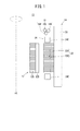
図1は、電動機10の断面の一部を示す模式図である。電動機10は、例えばインナーロータ型の電動機であり、ロータコア12Aおよび磁石12Bを有する回転子12と、その回転子12の外側に設けられる固定子14と、固定子14に電流を供給するための動力線16と、不図示の中心点とを備える。
[Embodiment]
FIG. 1 is a schematic view showing a part of a cross section of the
固定子14は、ハウジング20、ステータコア22およびコイル24を有する。ハウジング20は、ステータコア22およびコイル24などを収容するための樹脂製の部材であり、略円筒状に形成される。
The
ステータコア22は、電動機10の回転軸AXの周りに配置される鉄系金属製の部材であり、ハウジング20に固定される。ステータコア22は、コア本体22Aおよび複数のティース部22Bを有する。
The
コア本体22Aは、環状に形成されており、環状に形成されたコア本体22Aの軸(中心軸)は、電動機10の回転軸AXと一致する。なお、コア本体22Aは、複数の分割コア体を周方向に接合することで環状に形成されてもよい。複数のティース部22Bは、コア本体22Aの周方向に間隔をあけて設けられる。複数のティース部22Bの各々は、コア本体22Aの内周面からコア本体22Aの軸(中心軸)側に向かって突出する。
The core
コイル24は、複数の相に対応して複数有する。コイル24の相数は、一般的には、U相、V相およびW相の三相であるが、当該コイル24の相数は、三相以外であってもよい。複数の相の各々に対応する複数のコイル24は、複数のティース部22Bに設けられる。具体的には、複数のティース部22Bの各々に対して1つのコイル24が集中巻で巻かれる。なお、本実施の形態では、コイル24の相数は、U相、V相およびW相の三相とする。
The
複数のティース部22Bの各々に巻かれるコイル24のうち、ステータコア22における軸方向の端部から突出する一対のコイルエンド24Eの一方側に、動力線16が設けられる。動力線16は、各々の相に対応する複数のコイル24に相電流を流すものであり、本実施の形態では、U相電流を流すU相動力線16U、V相電流を流すV相動力線16VおよびW相電流を流すW相動力線16Wを有する。
A
図2は、複数のコイル24の接続状態を示す模式図である。図2の「△」は、コイル24の巻き方向を示している。なお、図2の「▲」については後述する。
FIG. 2 is a schematic view showing a connection state of a plurality of
複数のコイル24は、相ごとに直列に接続される。すなわち、U相に対応する複数のコイル24Uのコイル端が互いに接続されることでU相に対応する複数のコイル24Uが直列に接続される。一方、V相に対応する複数のコイル24Vのコイル端が互いに接続されることでV相に対応する複数のコイル24Vが直列に接続される。他方、W相に対応する複数のコイル24Wのコイル端が互いに接続されることでW相に対応する複数のコイル24Wが直列に接続される。
The plurality of
U相に対応するコイル24U同士の接続部CNU、V相に対応するコイル24V同士の接続部CNV、および、W相に対応するコイル24W同士の接続部CNWの各々は、ティース部22B(図1)を基準として動力線16側とは逆側に位置する。これにより、各々の接続部CNU、CNV、CNWが動力線16側に位置する場合に比べると、動力線16側における配線関係の占有量を小さくすることができる。
Each of the connection portion CNU between the
ここで、直列に接続された複数の相の各々に対応する複数のコイル24U、24V、24Wのうち、一端側のコイル24U、24V、24Wは、先頭のコイル24UL、24VL、24WLとする。また、直列に接続された複数の相の各々に対応する複数のコイル24U、24V、24Wのうち、他端側のコイル24U、24V、24Wは、最後尾のコイル24UE、24VE、24WEとする。
Here, a plurality of
先頭のコイル24UL、24VL、24WLの各々の先頭コイル端は、ティース部22B(図1)を基準として動力線16側に位置する。なお、先頭コイル端は、先頭のコイル24UL、24VL、24WLの各々における一対のコイル端のうち、2番目のコイル24U、24V、24Wのコイル端と接続されていない側のコイル端である。
Top of the
各々の先頭コイル端と動力線16とは、相ごとに結線される。すなわち、本実施の形態の固定子14は、動力線16側に位置する先頭コイル端と動力線16とを結線する第1の配線26を有する。
Each leading coil end and the
本実施の形態では、第1の配線26は、U相の先頭コイル端とU相動力線16Uとを結線するU相配線26Uと、V相の先頭コイル端とV相動力線16Vとを結線するV相配線26Vと、W相の先頭コイル端とW相動力線16Wとを結線するW相配線26Wとを有する。
In the present embodiment, the
一方、最後尾のコイル24UE、24VE、24WEの各々の最後尾コイル端は、ティース部22B(図1)を基準として動力線16側とは逆側に位置する。最後尾のコイル24UE、24VE、24WEの各々における一対のコイル端のうち、最後尾の1つ前のコイル24U、24V、24Wのコイル端と接続されていない側のコイル端である。
On the other hand, the end of the
図3は、先頭のコイル24ULと、最後尾のコイル24UEとの巻線数の違いを概念的に示す図である。なお、便宜上、図3では、U相における先頭のコイル24ULおよび最後尾のコイル24UEのみが示されている。ただし、V相における先頭のコイル24VLおよび最後尾のコイル24VEと、W相における先頭のコイル24WLおよび最後尾のコイル24WEについても、U相における先頭のコイル24ULおよび最後尾のコイル24UEと同じである。
Figure 3 is a
すなわち、最後尾のコイル24UE、24VE、24WEでは、一対のコイル端の双方が動力線16側とは逆側に延びており、一対のコイル端が延びる方向が相反していない。このため、最後尾のコイル24UE、24VE、24WEでは、巻線数が同等になる。
That is, in the end of the coil 24U E, 24V E, 24W E , and both
これに対し、先頭のコイル24UL、24VL、24WLでは、一対のコイル端の一方(先頭コイル端)が動力線16側に延び、一対のコイル端の他方が動力線16側とは逆側に延びており、一対のコイル端が延びる方向が相反する。このため、先頭のコイル24UL、24VL、24WLでは、巻線少数部SPTが生じる。
In contrast, the head of the
巻線少数部SPTは、先頭のコイル24UL、24VL、24WLにおいて最後尾のコイル24UE、24VE、24WEよりも巻線数が少ない部分であり、図2では「▲」として示されている。この巻線少数部SPTでは、上記のように、トルクリップルや磁気吸引力のアンバランスが生じ易い。
Winding fractional part SPT is the top of the
そこで、本実施の形態では、図2に示すように、中性点NPが動力線16側に設けられ、その中性点NPと、動力線16側とは反対側に位置する各々の相の最後尾コイル端とが、巻線少数部SPTを通って結線される。
Therefore, in the present embodiment, as shown in FIG. 2, a neutral point NP is provided on the
すなわち、本実施の形態の固定子14は、最後尾コイル端と中性点NPとを巻線少数部SPTを通って結線する第2の配線28を有する。この第2の配線28は、少なくとも巻線少数部SPTを通る箇所が絶縁性のチューブで覆われていてもよい。
That is, the
本実施の形態では、第2の配線28は、U相の最後尾コイル端と中性点NPとを結線するU相配線28Uと、V相の最後尾コイル端と中性点NPとを結線するV相配線28Vと、W相の最後尾コイル端と中性点NPとを結線するW相配線28Wとを有する。なお、中性点NPは、U相、V相およびW相の各々を接続する接続部位である。
In the present embodiment, the
このように、本実施の形態の固定子14は、動力線16側に位置する中性点NPと、動力線16側とは逆側に位置する最後尾コイル端とを巻線少数部SPTを介して結線することで、トルクリップルや磁気吸引力のアンバランスを生じ難くすることができる。したがって、本実施の形態では、電動機10の特性の悪化を抑制することができる。
As described above, the
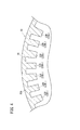
図4は、ステータコア22の一部を示す模式図である。なお、図4では、一対のコイルエンド24E(図1)の一方側からステータコア22を見た場合が示されている。ただし、図4では、コイル24や動力線16などが省略され、ステータコア22の一部のみが示されている。
FIG. 4 is a schematic view showing a part of the
複数のティース部22Bは、本実施の形態では、第1ティース部22B1および第2ティース部22B2を有する。第1ティース部22B1と第2ティース部22B2とは、コア本体22Aの周方向に沿って交互に設けられる。
The plurality of
第1ティース部22B1は、コア本体22Aの軸(中心軸)に対して直交する方向の断面の形状が矩形状である。第2ティース部22B2は、コア本体22Aの軸(中心軸)に対して直交する方向の断面の形状が台形状であり、当該断面の断面積が第1ティース部22B1よりも大きい。
The
コア本体22Aと1つの第2ティース部22B2との境界部分には、第2の配線28(図2)を通すための通路30が形成される。具体的には、複数の相の各々に対応する先頭のコイル24UL、24VL、24WL(図2)が巻かれる第2ティース部22B2の各々と、コア本体22Aとの境界部分に通路30が形成される。つまり、複数の相ごとに通路30が形成され、当該通路30には対応するU相配線28U、V相配線28VおよびW相配線28W(図2)のいずれかが通される。なお、図4では、便宜上、1つの通路30だけが示されている。
A
このように、第2の配線28を通すための通路30がステータコア22に形成されることで、巻線少数部SPTに対して第2の配線28を通し易くなる。また、第1ティース部22B1よりも大きい第2ティース部22B2とコア本体22Aとの境界部分に通路30が形成されることで、第1ティース部22B1とコア本体22Aとの境界部分に形成される場合に比べて、ステータコア22の強度の低下を抑制し、また大電流時の磁気飽和によるトルク低下を抑制できる。
By forming the
なお、本実施の形態では、通路30は、コア本体22Aと1つの第2ティース部22B2との境界部分の表面に窪みとして形成される。これにより、トルクリップルや磁気吸引力のアンバランスがより一段と生じ難くなるように、巻線少数部SPTに対して第2の配線28を接近させることができる。
In the present embodiment, the
〔変形例〕
以上、本発明の一例として上記実施の形態が説明されたが、本発明の技術的範囲は上記実施の形態に記載の範囲には限定されない。上記実施の形態に、多様な変更または改良を加えることが可能であることはもちろんである。その様な変更または改良を加えた形態も本発明の技術的範囲に含まれ得ることが、特許請求の範囲の記載から明らかである。
[Modification example]
Although the above-described embodiment has been described above as an example of the present invention, the technical scope of the present invention is not limited to the scope described in the above-described embodiment. Of course, it is possible to make various changes or improvements to the above embodiments. It is clear from the description of the claims that such modified or improved forms may also be included in the technical scope of the present invention.
上記の実施の形態では、複数のティース部22Bは、第1ティース部22B1および第2ティース部22B2を有していたが、第1ティース部22B1または第2ティース部22B2だけを有していてもよい。
In the above embodiment, the plurality of
上記の実施の形態では、通路30は、コア本体22Aと1つのティース部22B(第2ティース部22B2)との境界部分に形成されたが、コア本体22Aだけに形成されていてもよく、ティース部22Bだけに形成されていてもよい。
In the above embodiment, the
上記の実施の形態では、通路30は、ステータコア22の表面に形成される窪みであったが、貫通孔であってもよい。
In the above embodiment, the
なお、上記の実施の形態および変形例は、矛盾の生じない範囲で任意に組み合わされてもよい。 The above-described embodiments and modifications may be arbitrarily combined as long as there is no contradiction.
〔本発明〕
上記の実施の形態および変形例から把握し得る発明について、以下に記載する。
[Invention]
The inventions that can be grasped from the above embodiments and modifications are described below.
(第1の発明)
第1の発明は、環状のコア本体(22A)の内周面からコア本体(22A)の中心軸に向かって突出する複数のティース部(22B)に設けられ、複数の相の各々に対応する複数のコイル(24U、24V、24W)を有し、ティース部(22B)を基準として、複数の相の各々に対応する複数のコイル(24U、24V、24W)に相電流を流す動力線(16)側とは逆側において、複数の相の各々に対応する複数のコイル(24U、24V、24W)のコイル端が互いに接続されることで、相ごとに複数のコイル(24U、24V、24W)が直列に接続された固定子(14)である。
直列に接続された各々の相に対応する複数のコイル(24U、24V、24W)のうち、先頭のコイル(24UL、24VL、24WL)のコイル端は動力線(16)側に位置し、最後尾のコイル(24UE、24VE、24WE)のコイル端は逆側に位置している。
固定子(14)は、先頭のコイル(24UL、24VL、24WL)のコイル端と動力線(16)とを結線する第1の配線(26)と、最後尾のコイル(24UE、24VE、24WE)のコイル端と、動力線(16)側の中性点(NP)とを、先頭のコイル(24UL、24VL、24WL)において最後尾のコイル(24UE、24VE、24WE)よりも巻線数が少ない部分(巻線少数部SPT)を通って結線する第2の配線(28)と、を備える。
(First invention)
The first invention is provided on a plurality of teeth portions (22B) protruding from the inner peripheral surface of the annular core body (22A) toward the central axis of the core body (22A), and corresponds to each of the plurality of phases. A power line (16) having a plurality of coils (24U, 24V, 24W) and passing a phase current through a plurality of coils (24U, 24V, 24W) corresponding to each of the plurality of phases with reference to the teeth portion (22B). On the side opposite to the) side, the coil ends of the plurality of coils (24U, 24V, 24W) corresponding to each of the plurality of phases are connected to each other, so that a plurality of coils (24U, 24V, 24W) are connected to each phase. Is a stator (14) connected in series.
A plurality of coils corresponding to each phase connected in series (24U, 24V, 24W) of the coil end of the leading coil (24U L, 24V L, 24W L) is located in the power line (16) side , the end of the coil (24U E, 24V E, 24W E) coil end of is located on the opposite side.
The stator (14), the first coil (24U L, 24V L, 24W L) a first wiring for connecting the coil ends and the power lines and (16) and (26), the end of the coil (24U E, 24V E, and the coil end of 24W E), the power line (16) side of the neutral point and (NP), the top of the
このような固定子(14)では、先頭のコイル(24UL、24VL、24WL)において最後尾のコイル(24UE、24VE、24WE)よりも巻線数が少ない部分(巻線少数部SPT)を第2の配線(28)が通ることで、トルクリップルや磁気吸引力のアンバランスが生じ難くなり、電動機(10)の特性の悪化を抑制することができる。 In such stator (14), the top of the coil (24U L, 24V L, 24W L) at the end of the coil (24U E, 24V E, 24W E) number of windings than a small portion (winding minority By passing the second wiring (28) through the section SPT), the torque ripple and the imbalance of the magnetic attraction force are less likely to occur, and the deterioration of the characteristics of the motor (10) can be suppressed.
コア本体(22A)と1つのティース部(22B)との少なくとも一方には、第2の配線(28)を通すための通路(30)が形成されてもよい。これにより、巻線数が少ない部分(巻線少数部SPT)に対して第2の配線(28)を通し易くなる。 One of the teeth core body (22A) at least one of the in (22B), the passage for passing the second wiring (28) (30) may be formed. As a result, the second wiring (28) can be easily passed through the portion having a small number of windings (SPT having a small number of windings).
通路(30)は、コア本体(22A)と1つのティース部(22B)との境界部分の表面に形成される窪みであってもよい。これにより、トルクリップルや磁気吸引力のアンバランスがより一段と生じ難くなるように、巻線数が少ない部分(巻線少数部SPT)に対して第2の配線(28)を接近させることができる。 The passage (30) may be a recess formed on the surface of the boundary portion between the core body (22A) and one tooth portion (22B). As a result, the second wiring (28) can be brought closer to the portion having a small number of windings (the portion with a small number of windings SPT) so that the torque ripple and the imbalance of the magnetic attraction force are less likely to occur. ..
複数のティース部(22B)は、第1ティース部(22B1)と、コア本体(22A)の中心軸に対して直交する方向の断面積が第1ティース部(22B1)よりも大きい第2ティース部(22B2)とを有し、少なくとも第2ティース部(22B2)の1つには、第2の配線(28)を通すための通路(30)が形成されてもよい。これにより、第1ティース部(22B1)に形成される場合に比べて、ステータコア(22)の強度の低下を抑制し、また大電流時の磁気飽和によるトルク低下を抑制できる。
通路(30)は、コア本体(22A)と1つの第2ティース部(22B 2 )との境界部分の表面に形成される窪みであってもよい。これにより、トルクリップルや磁気吸引力のアンバランスがより一段と生じ難くなるように、巻線数が少ない部分(巻線少数部SPT)に対して第2の配線(28)を接近させることができる。
The plurality of teeth portions (22B) have a second cross-sectional area larger than that of the first teeth portion (22B 1 ) in the direction orthogonal to the central axis of the first teeth portion (22B 1) and the core body (22A). and a tooth portion (22B 2), into one of the second teeth even without least (22B 2) is a passage for passing the second wiring (28) (30) may be formed. As a result, it is possible to suppress a decrease in the strength of the stator core (22) and suppress a decrease in torque due to magnetic saturation at the time of a large current, as compared with the case where the first teeth portion (22B 1) is formed.
The passage (30) may be a recess formed on the surface of the boundary portion between the core body (22A) and one second tooth portion (22B 2). As a result, the second wiring (28) can be brought closer to the portion having a small number of windings (the portion with a small number of windings SPT) so that the torque ripple and the imbalance of the magnetic attraction force are less likely to occur. ..
(第2の発明)
第2の発明は、上記の固定子(14)と、回転子(12)と、を備える電動機(10)である。この電動機(10)では、上記の固定子(14)が備えられることにより、電動機(10)の特性の悪化を抑制することができる。
(Second invention)
A second invention is the above stator (14), a rotating rotor (12) and an electric motor with a (10). By providing the stator (14) in the electric motor (10), deterioration of the characteristics of the electric motor (10) can be suppressed.
10…電動機 12…回転子
14…固定子 16…動力線
20…ハウジング 22…ステータコア
24…コイル 26…第1の配線
28…第2の配線 30…通路
10 ...
Claims (6)
前記ティース部を基準として、複数の相の各々に対応する前記複数のコイルに相電流を流す動力線側とは逆側において、複数の相の各々に対応する前記複数のコイルのコイル端が互いに接続されることで、前記相ごとに前記複数のコイルが直列に接続された固定子であって、
直列に接続された各々の前記相に対応する前記複数のコイルのうち、先頭のコイルのコイル端は前記動力線側に位置し、最後尾のコイルのコイル端は前記逆側に位置しており、
前記先頭のコイルのコイル端と前記動力線とを結線する第1の配線と、
前記最後尾のコイルのコイル端と、前記動力線側の中性点とを、前記先頭のコイルにおいて前記最後尾のコイルよりも巻線数が少ない部分を通って結線する第2の配線と、
を備える、固定子。 It is provided on a plurality of teeth portions protruding from the inner peripheral surface of the annular core body toward the central axis of the core body, and has a plurality of coils corresponding to each of the plurality of phases.
With the teeth portion as a reference, the coil ends of the plurality of coils corresponding to each of the plurality of phases are on the opposite side to the power line side where the phase current is passed through the plurality of coils corresponding to each of the plurality of phases. By being connected, the plurality of coils are connected in series for each phase, and the stator is
Of the plurality of coils corresponding to the respective phases connected in series, the coil end of the first coil is located on the power line side, and the coil end of the last coil is located on the opposite side. ,
The first wiring that connects the coil end of the leading coil and the power line,
A second wiring that connects the coil end of the last coil and the neutral point on the power line side through a portion of the first coil that has fewer windings than the last coil.
A stator.
前記コア本体と1つの前記ティース部との少なくとも一方には、前記第2の配線を通すための通路が形成される、固定子。 The stator according to claim 1,
The core body and the least one of the one of the tooth portions, passages for passing the second wiring is formed, the stator.
前記通路は、前記コア本体と1つの前記ティース部との境界部分の表面に形成される窪みである、固定子。 The stator according to claim 2,
The passage is a stator, which is a recess formed on the surface of a boundary portion between the core body and one of the teeth portions.
前記複数のティース部は、第1ティース部と、前記コア本体の中心軸に対して直交する方向の断面積が前記第1ティース部よりも大きい第2ティース部とを有し、
少なくとも前記第2ティース部の1つには、前記第2の配線を通すための通路が形成される、固定子。 The stator according to claim 1,
The plurality of teeth portions have a first teeth portion and a second teeth portion whose cross-sectional area in a direction orthogonal to the central axis of the core body is larger than that of the first teeth portion.
One of the second tooth portion even without less, passages for passing the second wiring is formed, the stator.
前記通路は、前記コア本体と1つの前記第2ティース部との境界部分の表面に形成される窪みである、固定子。The passage is a stator, which is a recess formed on the surface of a boundary portion between the core body and one of the second teeth portions.
Priority Applications (5)
| Application Number | Priority Date | Filing Date | Title |
|---|---|---|---|
| JP2019051388A JP6912508B2 (en) | 2019-03-19 | 2019-03-19 | Stator and motor |
| US16/817,099 US11251664B2 (en) | 2019-03-19 | 2020-03-12 | Stator and electric motor |
| CN202010192836.1A CN111725932A (en) | 2019-03-19 | 2020-03-18 | Stator and motor |
| CN202020348890.6U CN211557006U (en) | 2019-03-19 | 2020-03-18 | Stator and motor |
| DE102020001815.7A DE102020001815A1 (en) | 2019-03-19 | 2020-03-19 | Stator and electric motor |
Applications Claiming Priority (1)
| Application Number | Priority Date | Filing Date | Title |
|---|---|---|---|
| JP2019051388A JP6912508B2 (en) | 2019-03-19 | 2019-03-19 | Stator and motor |
Publications (3)
| Publication Number | Publication Date |
|---|---|
| JP2020156179A JP2020156179A (en) | 2020-09-24 |
| JP2020156179A5 JP2020156179A5 (en) | 2020-11-12 |
| JP6912508B2 true JP6912508B2 (en) | 2021-08-04 |
Family
ID=72333848
Family Applications (1)
| Application Number | Title | Priority Date | Filing Date |
|---|---|---|---|
| JP2019051388A Active JP6912508B2 (en) | 2019-03-19 | 2019-03-19 | Stator and motor |
Country Status (4)
| Country | Link |
|---|---|
| US (1) | US11251664B2 (en) |
| JP (1) | JP6912508B2 (en) |
| CN (2) | CN111725932A (en) |
| DE (1) | DE102020001815A1 (en) |
Families Citing this family (2)
| Publication number | Priority date | Publication date | Assignee | Title |
|---|---|---|---|---|
| JP6912508B2 (en) * | 2019-03-19 | 2021-08-04 | ファナック株式会社 | Stator and motor |
| JP7348029B2 (en) * | 2019-10-31 | 2023-09-20 | ファナック株式会社 | stator and motor |
Family Cites Families (32)
| Publication number | Priority date | Publication date | Assignee | Title |
|---|---|---|---|---|
| US3519860A (en) * | 1968-04-22 | 1970-07-07 | Controls Co Of America | Arrangement for anchoring the leads in dynamoelectric machine |
| US3780324A (en) * | 1972-06-05 | 1973-12-18 | Lear Motors Corp | Adjustable speed induction motor system |
| IT1139350B (en) * | 1980-06-06 | 1986-09-24 | Papst Motoren Kg | DC external rotor commutatorless electric motor |
| US4999532A (en) * | 1990-01-26 | 1991-03-12 | Magnetek Universal Electric | Strain relief and support for electric motor wiring |
| JP2000037050A (en) * | 1998-07-16 | 2000-02-02 | Nippon Densan Corp | Motor |
| US6133663A (en) * | 1999-04-01 | 2000-10-17 | A. O. Smith Corporation | Brushless permanent magnet machine |
| JP3535452B2 (en) * | 2000-06-28 | 2004-06-07 | 株式会社日立製作所 | DC brushless motor |
| JP2002272074A (en) * | 2001-03-15 | 2002-09-20 | Moric Co Ltd | Permanent-magnet three-phase ac rotating electric machine |
| JP2005312182A (en) * | 2004-04-21 | 2005-11-04 | Denso Corp | Concentrated winding stator coil of rotary electric machine |
| JP2006211810A (en) * | 2005-01-27 | 2006-08-10 | Denso Corp | Segment connection type rotary electric machine |
| US7602137B2 (en) * | 2006-02-20 | 2009-10-13 | Black & Decker Inc. | Electronically commutated motor and control system |
| FI119748B (en) * | 2006-12-21 | 2009-02-27 | Kone Corp | Electric motor |
| JP5457869B2 (en) * | 2010-02-12 | 2014-04-02 | 東芝産業機器製造株式会社 | Rotating electric machine stator and rotating electric machine |
| JP5740931B2 (en) * | 2010-03-03 | 2015-07-01 | 日本電産株式会社 | Split stator and motor |
| JP5740930B2 (en) * | 2010-03-03 | 2015-07-01 | 日本電産株式会社 | Stator and motor |
| JP5656436B2 (en) * | 2010-03-31 | 2015-01-21 | 国産電機株式会社 | Stator coils, rotating electrical machines and automobiles |
| JP2012100497A (en) * | 2010-11-05 | 2012-05-24 | Toyota Motor Corp | Stator core |
| US20130200742A1 (en) * | 2012-02-08 | 2013-08-08 | Asmo Co., Ltd. | Stator, brushless motor, stator manufacturing method |
| US9748810B2 (en) * | 2012-03-13 | 2017-08-29 | Panasonic Intellectual Property Management Co., Ltd. | Motor and method for manufacturing stator therefor |
| JP5769883B2 (en) * | 2012-06-08 | 2015-08-26 | 三菱電機株式会社 | Rotating electric machine stator and method of manufacturing rotating electric machine stator |
| DE102013102124A1 (en) * | 2013-03-04 | 2014-09-04 | Ebm-Papst St. Georgen Gmbh & Co. Kg | Single-phase electric motor |
| JP2015111975A (en) * | 2013-12-06 | 2015-06-18 | 株式会社豊田自動織機 | Stator of dynamo-electric machine, and method of manufacturing stator of dynamo-electric machine |
| JP6004038B2 (en) * | 2014-05-16 | 2016-10-05 | デンソートリム株式会社 | Rotating electric machine for internal combustion engine and method for manufacturing the same |
| JP2016039642A (en) | 2014-08-05 | 2016-03-22 | トヨタ自動車株式会社 | Rotary electric machine stator |
| JP6539997B2 (en) * | 2014-11-25 | 2019-07-10 | 日本電産株式会社 | motor |
| US10454348B2 (en) * | 2015-09-17 | 2019-10-22 | Aisin Aw Co., Ltd. | Stator for rotating electrical machine |
| EP3370327A4 (en) * | 2015-10-28 | 2018-11-21 | Mitsubishi Electric Corporation | Rotary electric machine |
| JP6299729B2 (en) * | 2015-11-04 | 2018-03-28 | トヨタ自動車株式会社 | Rotating electrical machine stator |
| JP6608711B2 (en) * | 2016-01-15 | 2019-11-20 | 株式会社Soken | Rotating electric machine and stator |
| JP6650336B2 (en) * | 2016-04-28 | 2020-02-19 | 日立オートモティブシステムズエンジニアリング株式会社 | Rotating electric machine |
| JP7128702B2 (en) * | 2018-09-25 | 2022-08-31 | 株式会社Soken | Rotating electric machine |
| JP6912508B2 (en) * | 2019-03-19 | 2021-08-04 | ファナック株式会社 | Stator and motor |
-
2019
- 2019-03-19 JP JP2019051388A patent/JP6912508B2/en active Active
-
2020
- 2020-03-12 US US16/817,099 patent/US11251664B2/en active Active
- 2020-03-18 CN CN202010192836.1A patent/CN111725932A/en active Pending
- 2020-03-18 CN CN202020348890.6U patent/CN211557006U/en active Active
- 2020-03-19 DE DE102020001815.7A patent/DE102020001815A1/en active Pending
Also Published As
| Publication number | Publication date |
|---|---|
| CN111725932A (en) | 2020-09-29 |
| US11251664B2 (en) | 2022-02-15 |
| CN211557006U (en) | 2020-09-22 |
| US20200303975A1 (en) | 2020-09-24 |
| JP2020156179A (en) | 2020-09-24 |
| DE102020001815A1 (en) | 2020-09-24 |
Similar Documents
| Publication | Publication Date | Title |
|---|---|---|
| US10862355B2 (en) | Armature with a core having teeth of different circumferential widths and electric motor including the armature and a rotor | |
| JP4886624B2 (en) | Permanent magnet type rotating electrical machine and permanent magnet type rotating electrical machine system | |
| JP5570837B2 (en) | Electric motor | |
| US9438090B2 (en) | Method of assembling a rotary electric machine | |
| US8441164B2 (en) | Outer rotor motor | |
| CN108365717B (en) | Rotating electrical machine | |
| JP2006280121A (en) | Stator of rotary electric machine for vehicle | |
| JP4497102B2 (en) | Rotating electrical machine stator for vehicles | |
| US20120112600A1 (en) | Stator for electric rotating machine | |
| JP6912508B2 (en) | Stator and motor | |
| WO2017110419A1 (en) | Rotating electrical machine | |
| US20220263356A1 (en) | Motor | |
| JP5859516B2 (en) | Single pole motor phase | |
| JP6733568B2 (en) | Rotating electric machine | |
| WO2022059789A1 (en) | Stator and motor | |
| WO2016174730A1 (en) | Rotary electrical machine | |
| JP6651426B2 (en) | Stator of rotating electric machine, and rotating electric machine provided with the same | |
| JP2023047885A (en) | Rotary electric machine | |
| JP6047070B2 (en) | Armature and method for manufacturing armature | |
| JP2013128378A (en) | Permanent magnet type rotary electric machine | |
| JP6889066B2 (en) | Stator and motor | |
| JP5446140B2 (en) | Rotating electrical machine rotor | |
| JP2016034192A (en) | Stator and rotary electric machine | |
| JP2018170903A (en) | Stator of rotary electric machine | |
| JP7483577B2 (en) | Stator coil assembly and electric motor having the same |
Legal Events
| Date | Code | Title | Description |
|---|---|---|---|
| A621 | Written request for application examination |
Free format text: JAPANESE INTERMEDIATE CODE: A621 Effective date: 20200819 |
|
| A521 | Written amendment |
Free format text: JAPANESE INTERMEDIATE CODE: A523 Effective date: 20200901 |
|
| A977 | Report on retrieval |
Free format text: JAPANESE INTERMEDIATE CODE: A971007 Effective date: 20210526 |
|
| TRDD | Decision of grant or rejection written | ||
| A01 | Written decision to grant a patent or to grant a registration (utility model) |
Free format text: JAPANESE INTERMEDIATE CODE: A01 Effective date: 20210608 |
|
| A61 | First payment of annual fees (during grant procedure) |
Free format text: JAPANESE INTERMEDIATE CODE: A61 Effective date: 20210708 |
|
| R150 | Certificate of patent or registration of utility model |
Ref document number: 6912508 Country of ref document: JP Free format text: JAPANESE INTERMEDIATE CODE: R150 |