WO2017187645A1 - 部材供給方法、部材供給プログラムおよび部材供給システム - Google Patents
部材供給方法、部材供給プログラムおよび部材供給システム Download PDFInfo
- Publication number
- WO2017187645A1 WO2017187645A1 PCT/JP2016/063513 JP2016063513W WO2017187645A1 WO 2017187645 A1 WO2017187645 A1 WO 2017187645A1 JP 2016063513 W JP2016063513 W JP 2016063513W WO 2017187645 A1 WO2017187645 A1 WO 2017187645A1
- Authority
- WO
- WIPO (PCT)
- Prior art keywords
- work station
- work
- members
- unit
- time
- Prior art date
- Legal status (The legal status is an assumption and is not a legal conclusion. Google has not performed a legal analysis and makes no representation as to the accuracy of the status listed.)
- Ceased
Links
Images





Classifications
-
- B—PERFORMING OPERATIONS; TRANSPORTING
- B23—MACHINE TOOLS; METAL-WORKING NOT OTHERWISE PROVIDED FOR
- B23P—METAL-WORKING NOT OTHERWISE PROVIDED FOR; COMBINED OPERATIONS; UNIVERSAL MACHINE TOOLS
- B23P21/00—Machines for assembling a multiplicity of different parts to compose units, with or without preceding or subsequent working of such parts, e.g. with program control
-
- G—PHYSICS
- G05—CONTROLLING; REGULATING
- G05B—CONTROL OR REGULATING SYSTEMS IN GENERAL; FUNCTIONAL ELEMENTS OF SUCH SYSTEMS; MONITORING OR TESTING ARRANGEMENTS FOR SUCH SYSTEMS OR ELEMENTS
- G05B19/00—Program-control systems
- G05B19/02—Program-control systems electric
- G05B19/418—Total factory control, i.e. centrally controlling a plurality of machines, e.g. direct or distributed numerical control [DNC], flexible manufacturing systems [FMS], integrated manufacturing systems [IMS] or computer integrated manufacturing [CIM]
-
- Y—GENERAL TAGGING OF NEW TECHNOLOGICAL DEVELOPMENTS; GENERAL TAGGING OF CROSS-SECTIONAL TECHNOLOGIES SPANNING OVER SEVERAL SECTIONS OF THE IPC; TECHNICAL SUBJECTS COVERED BY FORMER USPC CROSS-REFERENCE ART COLLECTIONS [XRACs] AND DIGESTS
- Y02—TECHNOLOGIES OR APPLICATIONS FOR MITIGATION OR ADAPTATION AGAINST CLIMATE CHANGE
- Y02P—CLIMATE CHANGE MITIGATION TECHNOLOGIES IN THE PRODUCTION OR PROCESSING OF GOODS
- Y02P90/00—Enabling technologies with a potential contribution to greenhouse gas [GHG] emissions mitigation
- Y02P90/02—Total factory control, e.g. smart factories, flexible manufacturing systems [FMS] or integrated manufacturing systems [IMS]
-
- Y—GENERAL TAGGING OF NEW TECHNOLOGICAL DEVELOPMENTS; GENERAL TAGGING OF CROSS-SECTIONAL TECHNOLOGIES SPANNING OVER SEVERAL SECTIONS OF THE IPC; TECHNICAL SUBJECTS COVERED BY FORMER USPC CROSS-REFERENCE ART COLLECTIONS [XRACs] AND DIGESTS
- Y02—TECHNOLOGIES OR APPLICATIONS FOR MITIGATION OR ADAPTATION AGAINST CLIMATE CHANGE
- Y02P—CLIMATE CHANGE MITIGATION TECHNOLOGIES IN THE PRODUCTION OR PROCESSING OF GOODS
- Y02P90/00—Enabling technologies with a potential contribution to greenhouse gas [GHG] emissions mitigation
- Y02P90/60—Electric or hybrid propulsion means for production processes
Definitions
- the present invention relates to a member supply method, a member supply program, and a member supply system.
- a production line in a factory there may be a plurality of work stations where workers and robots work.
- work such as assembling of members is performed on the product flowing through the production line.
- the worker contacts the member supply staff to supply the members.
- the person in charge of supply periodically circulates a predetermined route, for example, and supplies members to each work station.
- the part running time is calculated from the remaining part data of each work station and the average part usage, and the priority of parts supply to each work station is calculated based on the calculation result, and replenishment is performed from a prestored replenishment route pattern. It has been proposed to select a route.
- the present invention provides a member supply method, a member supply program, and a member supply system that can efficiently supply members according to the situation.
- the method for supplying a member is performed when the carriage that transports the member to each work station where each work in the work process starts starts from a preparation station that prepares the member, or for a certain work station.
- the computer executes the next process.
- the computer executes a process of acquiring the remaining number of members for the members used for work at each work station from each work station.
- the computer executes a process of predicting the member expiration time of each work station based on the obtained number of members for each work station.
- the computer executes a process of searching for a route for supplying a member to each work station based on the movement time and movement distance between the work stations and the predicted member run-out time.
- a computer executes a process of instructing the work station to supply a member next based on the searched route.
- FIG. 1 is a block diagram illustrating an example of a configuration of a member supply system according to the first embodiment.
- FIG. 2 is a diagram illustrating an example of member supply.
- FIG. 3 is a diagram illustrating an example of the travel time storage unit.
- FIG. 4 is a diagram illustrating an example of the movement distance storage unit.
- FIG. 5 is a diagram illustrating an example of the station status storage unit.
- FIG. 6 is a diagram illustrating an example of prediction of the member run-out time.
- FIG. 7 is a diagram illustrating an example of a member supply path.
- FIG. 8 is a diagram illustrating an example of updating the member supply path.
- FIG. 9 is a flowchart illustrating an example of a member supply process according to the first embodiment.
- FIG. 9 is a flowchart illustrating an example of a member supply process according to the first embodiment.
- FIG. 10 is a block diagram illustrating an example of the configuration of the member supply system according to the second embodiment.
- FIG. 11 is a diagram illustrating an example of the member run-out time.
- FIG. 12 is a flowchart illustrating an example of a member supply process according to the second embodiment.
- FIG. 13 is a diagram illustrating an example of a computer that executes a member supply program.
- FIG. 1 is a block diagram illustrating an example of a configuration of a member supply system according to the first embodiment.
- a member supply system 1 illustrated in FIG. 1 includes a measuring device 10, a terminal device 20, and an information processing device 100.
- the measuring device 10 is disposed, for example, at each work station ST11 to STmn (m and n are arbitrary integers) on a production line to which the member supply system 1 is applied.
- the member supply system 1 is not limited to the number of measuring devices 10 and may include an arbitrary number of measuring devices 10.
- Each work station ST11 to STmn in the production line is an example of each work station where each work in the work process is performed. Further, in the following description, when the work stations ST11 to STmn are not distinguished, they may be simply expressed as work stations.
- the information processing apparatus 100 is a single apparatus, but each functional unit and each storage unit of the information processing apparatus 100 are configured using a cloud computing service such as SaaS (Software as a Service). May be.
- SaaS Software as a Service
- the measurement device 10, the terminal device 20, and the information processing device 100 are connected via a network N so that they can communicate with each other.
- a network N any type of communication network such as the Internet, LAN (Local Area Network), and VPN (Virtual Private Network) can be adopted regardless of wired or wireless.
- the measuring device 10 measures the remaining number of members used for work at each work station of the production line, and transmits the measured number of members to the information processing device 100.
- a built-in computer can be employed as the measuring device 10.
- the terminal device 20 is installed, for example, on a carriage used by the member supplier, and displays the instruction of the work station that supplies the next member received from the information processing device 100.
- a tablet terminal can be adopted.
- the terminal device 20 can also employ, for example, a portable personal computer, a mobile communication terminal such as a smartphone or a mobile phone, and the like.
- the terminal device 20 may use a computer for controlling the automatic guided vehicle.
- the information processing apparatus 100 when the carriage that transports the member to each work station where each work in the work process starts, the supply of the member to the certain work station is completed when the carriage starts from the preparation station that prepares the member. If so, perform the following process:
- the information processing apparatus 100 acquires the remaining number of members for the members used for the work at each work station from the measurement device 10 of each work station.
- the information processing apparatus 100 predicts the member expiration time of each work station based on the acquired number of members for each work station.
- the information processing apparatus 100 searches for a route for supplying a member to each work station based on the movement time and movement distance between the work stations and the predicted member run-out time. Based on the searched route, the information processing apparatus 100 instructs the terminal device 20 of a work station that supplies the next member. Thereby, the information processing apparatus 100 can supply a member efficiently according to a condition.
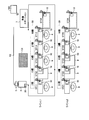
- FIG. 2 is a diagram illustrating an example of member supply.
- members are supplied to a production line having a line L1 with a tact time of 15 seconds and a line L2 with a tact time of 30 seconds.
- the line L1 has work stations ST11 to ST16.
- the assembly worker 8 performs work.
- the robot 9 performs work.
- the work station ST16 is a temporary storage place for products produced in the line L1.
- the line L2 has work stations ST21 to ST26.
- the assembly worker 8 performs work.
- the robot 9 performs work.
- the measuring device 10 is installed in the member storage area, and the remaining number of members is measured. Note that the measuring devices 10 of the work stations ST16 and ST26 measure the number of products produced.
- Each measuring device 10 starts transmission of the measured number of members or products to the information processing device 100 with the start of production on the production line. That is, the information processing apparatus 100 receives and acquires the number of members or the number of products of the work stations ST11 to ST16 and ST21 to ST26 in real time.
- the terminal device 20 is installed on the cart 6 used by the member supplier 5. On the terminal device 20, an instruction of the next work station from the information processing device 100 is displayed.
- the member supplier 5 loads members to be supplied to the carriage 6 at the preparation station 7, and supplies members to the lines L1 and L2 through the route R1, for example.
- the route R1 is set so as to avoid an obstacle G1 such as a pillar.
- operations such as taking out packed members and collecting the number of pieces to be supplied at a time are performed.
- the remaining number of members in each work station is shown in a region 30.
- the member supplier 5 first heads to supply members to the work station ST11 in which the remaining number of members is two.
- the measurement device 10 includes a communication unit 11, a measurement unit 12, and a control unit 13.
- the measuring apparatus 10 may include various functional units included in a known computer, for example, functional units such as various input devices and audio output devices, in addition to the functional units illustrated in FIG.
- the communication unit 11 is realized by, for example, a NIC (Network Interface Card) or a communication module such as a wireless LAN.
- the communication unit 11 is a communication interface that is connected to the information processing apparatus 100 via a network N in a wired or wireless manner and manages information communication with the information processing apparatus 100.
- the communication unit 11 transmits the number of members input from the control unit 13 to the information processing apparatus 100. Further, the communication unit 11 receives an end instruction from the information processing apparatus 100.
- the communication unit 11 outputs an end instruction to the control unit 13.
- the measuring unit 12 can use, for example, a push button type counter. For example, when the assembly operator 8 takes out one member, the measurement unit 12 depresses the button to decrease the number of members by one. In addition, for example, when the member supplier 5 supplies a predetermined number, the measuring unit 12 increases the supply number using another button. The measuring unit 12 outputs the measured number of members to the control unit 13. Furthermore, the measurement unit 12 may measure the number of members by performing image processing such as template matching on an image captured using a camera that captures the member storage. In this case, the measurement unit 12 is a camera that captures an image of the member storage area, and outputs a captured image to the control unit 13.
- image processing such as template matching
- the measuring unit 12 measures the unit mass in advance for each type of member, for example, installs an electronic balance or the like at the bottom of the member storage place, measures the mass of the member, and measures the number of members by dividing by the unit mass. May be.
- the measurement unit 12 is an electronic balance, for example, and outputs the measured mass of the member to the control unit 13.
- the measurement unit 12 may measure the number of members by detecting the timing of work completion on the product.
- the measurement unit 12 is, for example, a sensor that detects the passage of a product, and outputs detection information to the control unit 13.
- the control unit 13 is realized, for example, by executing a program stored in an internal storage device using a RAM (Random Access Memory) as a work area by a CPU (Central Processing Unit), an MPU (Micro Processing Unit), or the like. Is done.
- the control unit 13 may be realized by an integrated circuit such as ASIC (Application Specific Integrated Circuit) or FPGA (Field Programmable Gate Array).
- the control unit 13 When the number of members is input from the measurement unit 12, the control unit 13 transmits the input number of members to the information processing apparatus 100 via the communication unit 11 and the network N.
- the control unit 13 measures the number of members by performing image processing such as template matching on the input captured image. Template matching can be applied, for example, when small parts are loaded on a tray.
- the control unit 13 transmits the measured number of members to the information processing apparatus 100 via the communication unit 11 and the network N.
- the control unit 13 measures the number of members by dividing the mass of the input member by the unit mass.
- the control unit 13 transmits the measured number of members to the information processing apparatus 100 via the communication unit 11 and the network N.
- the control part 13 measures the number of members based on the input detection information, when the measurement part 12 is a sensor which detects passage of a product.
- the control unit 13 transmits the measured number of members to the information processing apparatus 100 via the communication unit 11 and the network N.
- the measurement unit 12 receives continuous information such as a camera or an electronic balance
- the control unit 13 transmits the number of members when there is a change in the information input from the measurement unit 12. You may make it do.
- control unit 13 when the control unit 13 receives an end instruction from the information processing apparatus 100 via the communication unit 11 and the network N, the control unit 13 executes a shutdown process of the measurement apparatus 10.
- the terminal device 20 includes a communication unit 21, a display unit 22, and a control unit 23.
- the terminal device 20 may include various functional units included in a known computer other than the functional units illustrated in FIG. 1, for example, functional units such as various input devices and audio output devices.
- the communication unit 21 is realized by a communication module such as a wireless LAN, for example.
- the communication unit 21 is a communication interface that is wirelessly connected to the information processing apparatus 100 via the network N and manages information communication with the information processing apparatus 100.
- the communication unit 21 receives instruction information and an end instruction from the information processing apparatus 100.
- the communication unit 21 outputs the received instruction information and the end instruction to the control unit 23.
- the display unit 22 is a display device for displaying various information.
- the display unit 22 is realized by, for example, a liquid crystal display as a display device.
- the display unit 22 displays various screens such as a screen for displaying instruction information input from the control unit 23.
- the control unit 23 is realized by, for example, a program stored in an internal storage device being executed by the CPU or MPU using the RAM as a work area.
- the control unit 23 may be realized by an integrated circuit such as an ASIC or FPGA, for example.
- the control unit 23 is an example of a display control unit.
- the control unit 23 When receiving the instruction information from the information processing apparatus 100 via the communication unit 21 and the network N, the control unit 23 generates a screen for displaying the instruction information and causes the display unit 22 to display the screen. Further, for example, when the control unit 23 detects that the preparation station 7 is departed by an operation of the operation unit (not shown) of the member supplier 5, the control unit 23 departs to the information processing apparatus 100 via the communication unit 21 and the network N. Send information.
- control unit 23 When the control unit 23 receives an end instruction from the information processing apparatus 100 via the communication unit 21 and the network N, the control unit 23 causes the display unit 22 to display the end of work.
- the information processing apparatus 100 includes a communication unit 110, a storage unit 120, and a control unit 130.
- the information processing apparatus 100 may include various functional units included in known computers, for example, functional units such as various input devices and audio output devices, in addition to the functional units illustrated in FIG.
- the communication unit 110 is realized by, for example, a NIC or a communication module such as a wireless LAN.
- the communication unit 110 is a communication interface that is connected to the measurement device 10 and the terminal device 20 via the network N in a wired or wireless manner and manages information communication between the measurement device 10 and the terminal device 20.
- the communication unit 110 receives the number of members from the measurement device 10.
- the communication unit 110 outputs the received number of members to the control unit 130.
- the communication unit 110 transmits instruction information input from the control unit 130 to the terminal device 20.
- the communication unit 110 receives departure information from the terminal device 20.
- the communication unit 110 outputs the received departure information to the control unit 130.
- the storage unit 120 is realized by, for example, a semiconductor memory device such as a RAM or a flash memory, or a storage device such as a hard disk or an optical disk.
- the storage unit 120 includes a travel time storage unit 121, a travel distance storage unit 122, and a station status storage unit 123.
- the storage unit 120 stores information used for processing in the control unit 130.
- the movement time storage unit 121 stores the movement time between the preparation station or the work station.
- FIG. 3 is a diagram illustrating an example of the travel time storage unit. As illustrated in FIG. 3, the travel time storage unit 121 includes items representing a preparation station and a work station such as “preparation ST”, “ST11”, and “ST12” in rows and columns, respectively. The cell represented by each matrix is information indicating the travel time between the preparation station or the work station. The movement time is expressed in seconds, for example.
- the movement time storage unit 121 for example, the value “2.5” in the row “ST11” and the column “ST12” indicates that the movement from the work station ST11 to the work station ST12 takes 2.5 seconds. Note that a cell of a preparation station or work station having the same row and column is indicated by “ ⁇ ” because it does not move.
- the movement time of the movement time storage unit 121 is obtained by adding the time required to supply the members.
- the movement distance storage unit 122 stores the movement distance between the preparation stations or the work stations.
- FIG. 4 is a diagram illustrating an example of the movement distance storage unit. As shown in FIG. 4, the moving distance storage unit 122 includes items representing a preparation station and a work station such as “preparation ST”, “ST11”, and “ST12” in rows and columns, respectively. The cell represented by each matrix is information indicating the movement distance between the preparation station or the work station. The movement distance is expressed in meters (m), for example.
- the value “16.5” in the row “ST13” and the column “ST21” indicates that the movement distance between the work station ST13 and the work station ST21 is 16.5 m. Note that a cell of a preparation station or work station having the same row and column is indicated by “ ⁇ ” because it does not move.
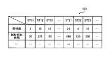
- the station status storage unit 123 stores the number of members and the member run-out time at each work station.
- FIG. 5 is a diagram illustrating an example of the station status storage unit. As illustrated in FIG. 5, the station status storage unit 123 includes items such as “number of members” and “time of member expiration” as rows. The station status storage unit 123 includes items representing work stations such as “ST11” and “ST12” as columns. In other words, the station status storage unit 123 stores the number of members and the member expiration time for each work station.
- “Number of members” is information indicating the number of remaining members in the member storage area of each work station. “Member outage time” indicates an estimated time for which there is no member predicted based on the number of remaining members for each work station. “Member out time” indicates, for example, how many seconds the member runs out. In the example of FIG. 5, the work station ST11 indicates that the remaining number of members is “2” and that the member is cut out after “30” seconds.
- control unit 130 is realized by, for example, a CPU or MPU executing a program stored in an internal storage device using the RAM as a work area.
- the control unit 130 may be realized by an integrated circuit such as ASIC or FPGA, for example.
- the control unit 130 includes an acquisition unit 131, a prediction unit 132, a search unit 133, and an instruction unit 134, and implements or executes information processing functions and operations described below. Note that the internal configuration of the control unit 130 is not limited to the configuration illustrated in FIG. 1, and may be another configuration as long as the information processing described below is performed.
- the acquisition unit 131 starts receiving the number of members from the measurement device 10 of each work station via the communication unit 110 and the network N. In addition, the acquisition unit 131 waits for reception of departure information transmitted from the terminal device 20 provided in the carriage 6 that transports a member to each work station.
- the acquisition unit 131 determines whether or not departure information has been received. That is, the acquisition unit 131 determines whether the cart 6 has left the preparation station 7. When the cart 6 departs from the preparation station 7, the acquisition unit 131 acquires the received number of members of each work station, and stores it in the station status storage unit 123 in association with the work station. When the acquisition unit 131 stores the number of members in the station status storage unit 123, the acquisition unit 131 outputs a prediction instruction to the prediction unit 132. The acquisition unit 131 waits for the departure of the carriage 6 when the carriage 6 has not departed from the preparation station 7.
- the acquisition unit 131 When the instruction information is input from the instruction unit 134, the acquisition unit 131 starts to receive the number of members of the next work station included in the input instruction information from the measuring device 10 of the work station. That is, the acquisition unit 131 acquires the number of members of the work station to be supplied with the members. The acquisition unit 131 determines whether or not the member supply has been completed based on the acquired number of members. If the member supply has not been completed, the acquisition unit 131 repeats the determination of whether or not the member supply has been completed.
- the acquisition unit 131 determines whether there is a work-in-process when the material supply is completed. When there is a work-in-progress, the acquisition unit 131 receives and acquires the remaining number of members for each member used for work at each work station from each work station. In other words, when the carriage 6 has already departed from the preparation station 7 and the supply of members to a certain work station has been completed, the acquisition unit 131 remains on the members used for work at each work station from each work station. The number of members is received and acquired. The acquisition unit 131 stores the acquired number of members in the station status storage unit 123 in association with the work station.
- the acquisition unit 131 determines that the work on the lines L1 and L2 has been completed, and ends the measurement device 10 and the terminal device 20 via the communication unit 110 and the network N, for example. Send instructions.
- the prediction unit 132 When the prediction instruction is input from the acquisition unit 131, the prediction unit 132 refers to the station status storage unit 123, and predicts the member expiration time of each work station based on the number of members for each work station. The prediction unit 132 associates the predicted member run-out time with the work station and stores it in the station status storage unit 123. The prediction unit 132 outputs a search instruction to the search unit 133 after storing the member expiration time in the station status storage unit 123.
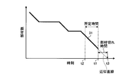
- FIG. 6 is a diagram illustrating an example of prediction of the member run-out time.
- the prediction unit 132 predicts the member run-out time by linearly approximating the time transition of the number of members from the current time t1 to a predetermined time before.
- the prediction unit 132 linearly approximates the graph 31 with respect to the time transition of the number of members from the time t2 that is a predetermined time before the current time t1 to the current time t1.
- the prediction unit 132 obtains a time t3 when the number of members becomes zero based on the approximate straight line of the graph 31.
- the prediction unit 132 predicts the difference between the current time t1 and the time t3 as the member run-out time.
- the prediction unit 132 refers to the production plan information in addition to the linear approximation, and then uses up the current number of members based on the number of products using the members and the tact times of the lines L1 and L2. It is also possible to predict the member run-out time by predicting.
- the predicting unit 132 is filled with a temporary storage space that is full based on the upper limit number of products in the temporary storage space with respect to the temporary storage space of the products produced in the line L1, as in the work station ST16 shown in FIG. Time may be predicted. In this case, the prediction unit 132 stores the predicted full time in the station status storage unit 123 in association with the work station.
- the search unit 133 searches for a member supply route.
- the search unit 133 refers to the travel time storage unit 121, the travel distance storage unit 122, and the station status storage unit 123, and determines each work based on the travel time and travel distance between work stations and the predicted member run-out time. The route for supplying the member to the station is searched.
- the search unit 133 extracts a route that does not cause a member breakage in all the work stations, starting from the preparation station 7 or the work station that has supplied the members most recently. Based on the movement time between the respective work stations and the predicted member cut time, the search unit 133 causes member cuts at all the work stations from among the routes for supplying the members to all other work stations. Extract no routes. Next, the search unit 133 selects a route having the shortest moving distance of the entire route based on the moving distance between the work stations from the extracted routes. Search unit 133 outputs the selected route to instruction unit 134.
- the search unit 133 may group the ranges including work stations that are likely to run out of members, and rank them. In addition, when there are many target work stations and the number of candidate routes becomes enormous, the search unit 133 uses a local search algorithm or an annealing method to obtain a local solution instead of an exact solution. Also good. Further, the search unit 133 may search to include the product collection in the route so that the temporary storage place for the product does not become full.
- the instruction unit 134 instructs a work station to supply the next member based on the input route. That is, the instruction unit 134 generates instruction information for instructing a work station to which a member is to be supplied next in the input route.
- the instruction unit 134 transmits the generated instruction information to the terminal device 20 via the communication unit 110 and the network N to be displayed. Also, the instruction unit 134 outputs instruction information to the acquisition unit 131.
- FIG. 7 is a diagram illustrating an example of a member supply path.
- FIG. 7 shows an example of supplying members to the lines L1 and L2 shown in FIG.
- the work station ST11 is displayed and instructed as the next work station on the terminal device 20 according to the route R2, and immediately before the member is supplied to the work station ST11.
- the work stations to be supplied on the route R2 are the work stations ST15, ST22, and ST24.
- members are scheduled to be supplied in the order of work stations ST22, ST24, ST15.
- FIG. 8 is a diagram illustrating an example of updating the member supply path.
- the member supplier 5 is in a state of supplying members from the state of FIG. 7 to the work station ST11 and going to the next work station.
- the information processing apparatus 100 receives the number of members after supplying the members from the measuring apparatus 10 of the work station ST11, the information processing apparatus 100 searches for a route again. Note that the number of members in all work stations is updated when the number of members after the member supply is received.
- the information processing apparatus 100 updates the subsequent route from the route R2 to the route R3, for example, when a trouble occurs in the work station ST15 and the number of members becomes smaller than usual.
- the route R3 is changed so that the members are supplied in the order of the work stations ST15, ST24, ST22.
- the member supply system 1 since the route is updated even during the member supply, the member can be efficiently supplied according to the situation.
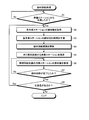
- FIG. 9 is a flowchart illustrating an example of a member supply process according to the first embodiment.
- the measuring device 10 of each work station starts measuring the number of members and starts transmitting the number of members to the information processing device 100.
- the acquisition unit 131 of the information processing device 100 starts receiving the number of members from the measurement device 10 of each work station.
- the acquisition unit 131 waits for reception of departure information transmitted from the terminal device 20 provided in the carriage 6.
- the acquisition unit 131 determines whether the carriage 6 has departed from the preparation station 7 (step S1). When the cart 6 departs from the preparation station 7 (step S1: affirmative), the acquisition unit 131 acquires the number of members of each received work station (step S2), and stores the station status in association with the work station. Store in the unit 123. When the acquisition unit 131 stores the number of members in the station status storage unit 123, the acquisition unit 131 outputs a prediction instruction to the prediction unit 132. If the carriage 6 has not left the preparation station 7 (No at Step S1), the acquisition unit 131 waits for the departure of the carriage 6 and repeats the determination at Step S1.
- the prediction unit 132 predicts the member expiration time of each work station based on the number of members for each work station (step S3).
- the prediction unit 132 associates the predicted member run-out time with the work station, stores it in the station status storage unit 123, and outputs a search instruction to the search unit 133.
- the search unit 133 searches for a member supply route based on the movement time and movement distance between work stations and the predicted member run-out time (step S4). That is, the search unit 133 extracts a route that does not cause a member breakage at all work stations. The search unit 133 selects a route having the shortest moving distance of the entire route based on the moving distance between the work stations from the extracted routes. Search unit 133 outputs the selected route to instruction unit 134.
- the instruction unit 134 When the route selected from the search unit 133 is input, the instruction unit 134 generates information on an instruction for instructing a work station to which a member is to be supplied next in the input route. The instruction unit 134 transmits the generated instruction information to the terminal device 20, and instructs the work station to supply the next member (step S5). Also, the instruction unit 134 outputs instruction information to the acquisition unit 131. The terminal device 20 displays the received instruction information.
- the acquisition unit 131 of the information processing apparatus 100 acquires the number of members of the work station that is a member supply target (step S6).
- the acquisition unit 131 determines whether the member supply is completed based on the acquired number of members (step S7). If the member supply has not been completed (No at Step S7), the acquisition unit 131 returns to Step S6.
- Step S7 the acquisition unit 131 determines whether or not there is a work in progress (Step S8). If there is a work in progress (step S8: affirmative), the acquisition unit 131 returns to step S2. If there is no work in progress (No at Step S8), the acquisition unit 131 determines that the work on the lines L1 and L2 has been completed, transmits an end instruction to the measuring device 10 and the terminal device 20, and the member The supply process ends. Note that when the measurement apparatus 10 receives an end instruction from the information processing apparatus 100, the measurement apparatus 10 executes a shutdown process of the measurement apparatus 10. In addition, when receiving an end instruction from the information processing apparatus 100, the terminal device 20 causes the display unit 22 to display the end of work.
- the information processing apparatus 100 can supply a member efficiently according to a condition.
- the information processing apparatus 100 can efficiently supply members even in a high-mix low-volume production line in which members to be used frequently change.
- the information processing apparatus 100 can shorten the moving distance of the member supplier 5, it can increase the number of the work stations which the member supplier 5 takes charge of. Therefore, the number of member suppliers 5 in the entire factory can be reduced.
- the information processing apparatus 100 is used when the carriage 6 that transports a member to each work station where each work in the work process starts, starts from a preparation station that prepares the member, or for a certain work station.
- the information processing apparatus 100 acquires the remaining number of members for each member used for work at each work station from each work station. Further, the information processing apparatus 100 predicts the member expiration time of each work station based on the acquired number of members for each work station. Further, the information processing apparatus 100 searches for a route for supplying a member to each work station based on the movement time and movement distance between the work stations and the predicted member run-out time. Further, the information processing apparatus 100 instructs a work station that supplies the next member based on the searched route. As a result, members can be supplied efficiently according to the situation.
- the information processing apparatus 100 predicts a member run-out time by linearly approximating the time transition of the number of members from the current time to a predetermined time before. As a result, the member run-out time can be easily predicted.
- the route search is performed for all the work stations to be supplied with the members. However, the route search is performed only for the work stations whose member run time is less than the preset reference time.
- the embodiment in this case will be described as Example 2.
- FIG. 10 is a block diagram illustrating an example of the configuration of the member supply system according to the second embodiment.
- symbol is attached
- the control unit 230 of the information processing apparatus 200 in the member supply system 2 according to the second embodiment includes a search unit 233 instead of the search unit 133 as compared with the control unit 130 of the information processing apparatus 100 according to the first embodiment.
- a search instruction is input from the prediction unit 132 to the search unit 233.
- the prediction unit 132 of the information processing device 200 outputs a search instruction to the search unit 233.
- the search unit 233 refers to the station status storage unit 123 and selects a work station that is less than a preset reference time. That is, the search unit 233 limits the target work stations to be supplied with members.
- the reference time can be set to 240 seconds (4 minutes), for example.
- the search unit 233 refers to the travel time storage unit 121 and the travel distance storage unit 122 and reads the travel time and travel distance corresponding to the selected work station.
- the search unit 233 searches for a route for supplying the member to each work station based on the member run-out time of the selected work station and the corresponding moving time and moving distance.
- the search unit 233 extracts a route that does not cause a member breakage at the selected work station, starting from the preparation station or the work station that has supplied the member most recently. Based on the movement time between each selected work station and the predicted member cut-off time, the search unit 233 cuts the member at the selected work station from the route for supplying the member to another selected work station. Extract routes that do not cause Next, the search unit 233 selects a route having the shortest travel distance of the entire route based on the travel distance between the selected work stations from the extracted routes. Search unit 233 outputs the selected route to instruction unit 134.
- FIG. 11 is a diagram illustrating an example of the member run-out time.
- the reference time is 240 seconds
- the three work stations ST21, ST23 and ST25 shown in the area 42 can be excluded from the target.
- FIG. 12 is a flowchart illustrating an example of a member supply process according to the second embodiment.
- the processes in steps S1 to S3 and S5 to S8 are the same as those in the first embodiment, and thus the description thereof is omitted.
- the information processing apparatus 200 executes the following process following the process of step S3.
- a search instruction is input from the prediction unit 132 to the search unit 233.
- the search unit 233 refers to the station status storage unit 123 and selects a work station that is less than a preset reference time. That is, the search unit 233 limits the target work stations to be supplied with members (step S21).
- the search unit 233 searches for a member supply route based on the member expiration time of the selected work station and the corresponding movement time and movement distance (step S22). That is, the search unit 233 extracts a route that does not cause a member breakage at the selected work station. The search unit 233 selects a route having the shortest travel distance of the entire route based on the travel distance between the selected work stations from the extracted routes. The search unit 233 outputs the selected route to the instruction unit 134, and proceeds to step S5. As a result, the information processing apparatus 200 can obtain an exact route search solution in a short time. Further, the information processing apparatus 200 can shorten the waiting time until the next instruction.
- the information processing apparatus 200 searches for a route for supplying a member to each work station whose predicted member expiration time is less than a preset reference time. As a result, the exact route search solution can be obtained in a short time.
- the member supplier 5 loads the members on the carriage 6 and supplies the members to each work station.
- the terminal device 20 may be installed in the automatic guided vehicle, and the work station to which the automatic guided vehicle will go next may be determined based on the instruction information received by the terminal device 20. Thereby, the energy which moves an automatic guided vehicle can be reduced.
- each functional unit of the information processing apparatus 100 or 200 is a single apparatus, but the present invention is not limited to this.
- each functional unit of the information processing apparatus 100 or 200 may be configured using a cloud computing service such as SaaS, and the route search may be performed at higher speed by increasing the processing capability.
- each functional unit of the information processing apparatus 100 or 200 is configured using a cloud computing service such as SaaS, and is an efficient member for a plurality of production units in the same factory or production units in different factories. A supply path may be indicated.
- the preparation time including loading of members onto the carriage 6 at the preparation station 7 is omitted.
- the preparation time may be included in consideration of the loading amount of the carriage 6 or in the middle of the route. Then, the preparation station 7 may be replenished with members once again.
- the work time of the assembly worker 8 can be reduced, etc.
- the route and timing at the time of departure of the supplier 5 may not be optimal. Even in such a case, in each of the above-described embodiments, the member can be efficiently supplied depending on the situation.
- each component of each part illustrated does not necessarily need to be physically configured as illustrated.
- the specific form of distribution / integration of each unit is not limited to that shown in the figure, and all or a part thereof may be functionally or physically distributed / integrated in arbitrary units according to various loads or usage conditions. Can be configured.
- the search unit 133 and the instruction unit 134 may be integrated.
- the illustrated processes are not limited to the above-described order, and may be performed at the same time as long as the process contents are not contradictory, or may be performed in a different order.
- processing functions performed in each device may be executed entirely or arbitrarily on a CPU (or a microcomputer such as an MPU or MCU (Micro Controller Unit)).
- various processing functions may be executed in whole or in any part on a program that is analyzed and executed by a CPU (or a microcomputer such as an MPU or MCU) or on hardware based on wired logic. Needless to say, it is good.
- FIG. 13 is a diagram illustrating an example of a computer that executes a member supply program.
- the computer 300 includes a CPU 301 that executes various arithmetic processes, an input device 302 that receives data input, and a monitor 303.
- the computer 300 also includes a medium reading device 304 that reads a program and the like from a storage medium, an interface device 305 for connecting to various devices, and a communication device 306 for connecting to other information processing devices and the like by wire or wirelessly.
- Have The computer 300 also includes a RAM 307 that temporarily stores various types of information and a hard disk device 308. Each device 301 to 308 is connected to a bus 309.
- the hard disk device 308 stores a member supply program having the same functions as the processing units of the acquisition unit 131, the prediction unit 132, the search unit 133, and the instruction unit 134 illustrated in FIG.
- the hard disk device 308 stores a travel time storage unit 121, a travel distance storage unit 122, a station status storage unit 123, and various data for realizing a member supply program.
- the input device 302 receives input of various information such as operation information and management information from an administrator of the computer 300.
- the monitor 303 displays various screens such as a display screen for the administrator of the computer 300, for example.
- the interface device 305 is connected to, for example, a printing device.
- the communication device 306 has the same function as the communication unit 110 illustrated in FIG. 1, for example, is connected to the network N, and exchanges various types of information with the measurement device 10 and the terminal device 20.
- the CPU 301 reads out each program stored in the hard disk device 308, develops it in the RAM 307, and executes it to perform various processes. Further, these programs can cause the computer 300 to function as the acquisition unit 131, the prediction unit 132, the search unit 133, and the instruction unit 134 illustrated in FIG.
- the computer 300 may read and execute a program stored in a storage medium readable by the computer 300.
- the storage medium readable by the computer 300 corresponds to, for example, a portable recording medium such as a CD-ROM, a DVD disk, a USB (Universal Serial Bus) memory, a semiconductor memory such as a flash memory, a hard disk drive, and the like.
- the member supply program may be stored in a device connected to a public line, the Internet, a LAN, or the like, and the computer 300 may read and execute the member supply program from these.
Landscapes
- Engineering & Computer Science (AREA)
- Mechanical Engineering (AREA)
- General Engineering & Computer Science (AREA)
- Manufacturing & Machinery (AREA)
- Quality & Reliability (AREA)
- Physics & Mathematics (AREA)
- General Physics & Mathematics (AREA)
- Automation & Control Theory (AREA)
- General Factory Administration (AREA)
- Automatic Assembly (AREA)
Abstract
状況に応じて効率的に部材を供給できること。部材供給方法は、作業工程における各作業が行われる各作業ステーションに部材を運搬する台車が、部材を準備する準備ステーションから出発する場合、または、ある作業ステーションに対して部材の供給が完了した場合に、次の処理をコンピュータ(100)が実行する。コンピュータは、各作業ステーションから、それぞれの作業ステーションでの作業に用いる部材について残りの部材数を取得する。コンピュータは、取得した作業ステーションごとの部材数に基づいて、各作業ステーションの部材切れ時間を予測する。コンピュータは、作業ステーション間の移動時間および移動距離と、予測した部材切れ時間とに基づいて、各作業ステーションに対して部材を供給する経路を探索する。コンピュータは、探索した経路に基づいて、次に部材を供給する作業ステーションを指示する。
Description
本発明は、部材供給方法、部材供給プログラムおよび部材供給システムに関する。
工場における生産ラインでは、作業者やロボットが作業を行う作業ステーションが複数設けられることがある。作業ステーションでは、生産ラインを流れる製品に対して部材の組み付け等の作業が行われる。各作業ステーションでは、部材が不足すると、例えば、作業者が部材の供給担当者に対して連絡することで、部材の供給が行われる。供給担当者は、例えば、予め決定されたルートを周期的に巡回して、各作業ステーションに部材を供給する。また、各作業ステーションの部品残量データと平均部品使用量から部品切れ時間を演算し、演算結果に基づいて各作業ステーションに対する部品供給の優先順位を算出し、予め格納された補給経路パターンから補給経路を選択することが提案されている。
しかしながら、例えば、多品種少量生産を行う混流ラインでは、組み立てる部材が頻繁に変わるため、一度決められた経路に従って部材を供給していく間に、供給を要する部材数が変化する。このため、新たに供給が求められる部材を臨時に供給する回数が増加し、生産性の向上が困難となる場合がある。
一つの側面では、本発明は、状況に応じて効率的に部材を供給できる部材供給方法、部材供給プログラムおよび部材供給システムを提供することにある。
一つの態様では、部材供給方法は、作業工程における各作業が行われる各作業ステーションに部材を運搬する台車が、前記部材を準備する準備ステーションから出発する場合、または、ある作業ステーションに対して前記部材の供給が完了した場合に、次の処理をコンピュータが実行する。部材供給方法は、前記各作業ステーションから、それぞれの作業ステーションでの作業に用いる部材について残りの部材数を取得する処理をコンピュータが実行する。部材供給方法は、取得した前記作業ステーションごとの前記部材数に基づいて、前記各作業ステーションの部材切れ時間を予測する処理をコンピュータが実行する。部材供給方法は、前記作業ステーション間の移動時間および移動距離と、予測した前記部材切れ時間とに基づいて、前記各作業ステーションに対して部材を供給する経路を探索する処理をコンピュータが実行する。部材供給方法は、探索した前記経路に基づいて、次に部材を供給する前記作業ステーションを指示する処理をコンピュータが実行する。
状況に応じて効率的に部材を供給できる。
以下、図面に基づいて、本願の開示する部材供給方法、部材供給プログラムおよび部材供給システムの実施例を詳細に説明する。なお、本実施例により、開示技術が限定されるものではない。また、以下の実施例は、矛盾しない範囲で適宜組みあわせてもよい。
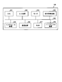
図1は、実施例1の部材供給システムの構成の一例を示すブロック図である。図1に示す部材供給システム1は、計測装置10と、端末装置20と、情報処理装置100とを有する。計測装置10は、例えば、部材供給システム1を適用する生産ライン上の各作業ステーションST11~STmn(m,nは、任意の整数。)に配置される。すなわち、部材供給システム1は、計測装置10の数は限定されず、任意の数の計測装置10を有してもよい。なお、生産ラインの各作業ステーションST11~STmnは、作業工程における各作業が行われる各作業ステーションの一例である。また、以下の説明では、各作業ステーションST11~STmnを区別しない場合には、単に作業ステーションと表現する場合がある。
また、図1では、端末装置20の数が1つの例を示したが、端末装置20の数は限定されず、任意の数の端末装置20を有してもよい。さらに、図1では、情報処理装置100は、1つの装置としたが、情報処理装置100の各機能部および各記憶部は、SaaS(Software as a Service)等のクラウドコンピューティングサービスを用いて構成されてもよい。
計測装置10、端末装置20および情報処理装置100の間は、ネットワークNを介して相互に通信可能に接続される。かかるネットワークNには、有線または無線を問わず、インターネットを始め、LAN(Local Area Network)やVPN(Virtual Private Network)などの任意の種類の通信網を採用できる。
計測装置10は、生産ラインの各作業ステーションでの作業に用いる部材について残りの部材数を計測し、計測された部材数を情報処理装置100に送信する。計測装置10は、例えば、組み込み型のコンピュータを採用できる。
端末装置20は、例えば、部材供給者が用いる台車に設置され、情報処理装置100から受信した、次に部材を供給する作業ステーションの指示を表示する。端末装置20の一例としては、タブレット端末を採用できる。端末装置20は、上記のタブレット端末の他にも、例えば、可搬型のパーソナルコンピュータや、スマートフォン、携帯電話機等の移動体通信端末等を採用することもできる。さらに、端末装置20は、無人搬送車を用いる場合には、無人搬送車の制御用コンピュータを用いてもよい。
情報処理装置100は、作業工程における各作業が行われる各作業ステーションに部材を運搬する台車が、部材を準備する準備ステーションから出発する場合、または、ある作業ステーションに対して部材の供給が完了した場合に、次の処理を実行する。情報処理装置100は、各作業ステーションの計測装置10から、それぞれの作業ステーションでの作業に用いる部材について残りの部材数を取得する。情報処理装置100は、取得した作業ステーションごとの部材数に基づいて、各作業ステーションの部材切れ時間を予測する。情報処理装置100は、作業ステーション間の移動時間および移動距離と、予測した部材切れ時間とに基づいて、各作業ステーションに対して部材を供給する経路を探索する。情報処理装置100は、探索した経路に基づいて、次に部材を供給する作業ステーションを端末装置20に指示する。これにより、情報処理装置100は、状況に応じて効率的に部材を供給できる。
ここで、図2を用いて、生産ラインへの部材供給について説明する。図2は、部材供給の一例を示す図である。図2に示すように、本実施例では、タクトタイムが15秒であるラインL1と、タクトタイムが30秒であるラインL2とを有する生産ラインに部材を供給する。ラインL1は、作業ステーションST11~ST16を有する。作業ステーションST11、ST13~ST15は、組立作業者8が作業を行う。作業ステーションST12は、ロボット9が作業を行う。また、作業ステーションST16は、ラインL1で生産された製品の仮置き場である。
ラインL2は、作業ステーションST21~ST26を有する。作業ステーションST21、ST24、ST25は、組立作業者8が作業を行う。作業ステーションST22、ST23は、ロボット9が作業を行う。各作業ステーションには、部材置き場に計測装置10が設置され、残りの部材数を計測する。なお、作業ステーションST16、ST26の計測装置10は、生産された製品の数を計測する。各計測装置10は、生産ラインでの生産開始に伴って、情報処理装置100に対して計測した部材数または製品数の送信を開始する。すなわち、情報処理装置100は、作業ステーションST11~ST16、ST21~ST26の部材数または製品数をリアルタイムで受信して取得する。
部材供給者5が用いる台車6には、端末装置20が設置される。端末装置20には、情報処理装置100から次に向かう作業ステーションの指示が表示される。部材供給者5は、準備ステーション7で台車6に供給する部材を積み込んで、例えば、経路R1を通ってラインL1、L2に部材を供給する。なお、経路R1は、例えば柱等の障害物G1を避けるように設定される。準備ステーション7では、梱包された部材を取り出したり、一度に供給する個数分を纏めたりといった作業が行われる。また、図2の例では、各作業ステーションの残りの部材数を領域30に示す。図2の例では、部材供給者5は、まず、残りの部材数が2個となっている作業ステーションST11に部材を供給するために向かうことになる。
次に、計測装置10の構成について説明する。図1に示すように、計測装置10は、通信部11と、計測部12と、制御部13とを有する。なお、計測装置10は、図1に示す機能部以外にも既知のコンピュータが有する各種の機能部、例えば各種の入力デバイスや音声出力デバイス等の機能部を有することとしてもかまわない。
通信部11は、例えば、NIC(Network Interface Card)や、無線LAN等の通信モジュール等によって実現される。通信部11は、ネットワークNを介して情報処理装置100と有線または無線で接続され、情報処理装置100との間で情報の通信を司る通信インタフェースである。通信部11は、制御部13から入力された部材数を情報処理装置100に送信する。また、通信部11は、情報処理装置100から終了指示を受信する。通信部11は、終了指示を制御部13に出力する。
計測部12は、例えば、押しボタン式のカウンタを用いることができる。計測部12は、例えば、組立作業者8が部材を1個取り出した際にボタンが押下されて部材数を1個減少させる。また、計測部12は、例えば、部材供給者5が所定の個数を供給すると、他のボタンを用いて供給個数を増加させる。計測部12は、計測した部材数を制御部13に出力する。さらに、計測部12は、部材置き場を撮像するカメラを用いて撮像された画像に対して、テンプレートマッチング等の画像処理を行うことで部材数を計測してもよい。この場合には、計測部12は、部材置き場を撮像するカメラであり、撮像画像を制御部13に出力する。
また、計測部12は、予め部材の種類ごとに単位質量を測定し、例えば部材置き場の底に電子天秤等を設置して部材の質量を測定し単位質量で除算することで部材数を計測してもよい。この場合には、計測部12は、例えば電子天秤であり、測定した部材の質量を制御部13に出力する。さらに、計測部12は、作業ステーションでロボット9による作業が行われる場合には、製品に対する作業完了等のタイミングを検出して部材数を計測してもよい。この場合には、計測部12は、例えば製品の通過を検知するセンサであり、検知情報を制御部13に出力する。
制御部13は、例えば、CPU(Central Processing Unit)やMPU(Micro Processing Unit)等によって、内部の記憶装置に記憶されているプログラムがRAM(Random Access Memory)を作業領域として実行されることにより実現される。また、制御部13は、例えば、ASIC(Application Specific Integrated Circuit)やFPGA(Field Programmable Gate Array)等の集積回路により実現されるようにしてもよい。
制御部13は、計測部12から部材数が入力されると、入力された部材数を通信部11およびネットワークNを介して、情報処理装置100に送信する。また、制御部13は、計測部12が部材置き場を撮像するカメラである場合には、入力された撮像画像に対してテンプレートマッチング等の画像処理を行うことで部材数を計測する。テンプレートマッチングは、例えば、小部品がトレーに積載されている場合等に適用できる。制御部13は、計測した部材数を通信部11およびネットワークNを介して、情報処理装置100に送信する。
さらに、制御部13は、計測部12が電子天秤である場合には、入力された部材の質量を単位質量で除算することで部材数を計測する。制御部13は、計測した部材数を通信部11およびネットワークNを介して、情報処理装置100に送信する。また、制御部13は、計測部12が製品の通過を検知するセンサである場合には、入力された検知情報に基づいて部材数を計測する。制御部13は、計測した部材数を通信部11およびネットワークNを介して、情報処理装置100に送信する。なお、制御部13は、計測部12がカメラまたは電子天秤等のように、連続した情報が入力される場合には、計測部12から入力される情報に変化がある場合に、部材数を送信するようにしてもよい。
また、制御部13は、通信部11およびネットワークNを介して、情報処理装置100から終了指示を受信すると、計測装置10のシャットダウン処理を実行する。
続いて、端末装置20の構成について説明する。図1に示すように、端末装置20は、通信部21と、表示部22と、制御部23とを有する。なお、端末装置20は、図1に示す機能部以外にも既知のコンピュータが有する各種の機能部、例えば各種の入力デバイスや音声出力デバイス等の機能部を有することとしてもかまわない。
通信部21は、例えば、無線LAN等の通信モジュール等によって実現される。通信部21は、ネットワークNを介して情報処理装置100と無線で接続され、情報処理装置100との間で情報の通信を司る通信インタフェースである。通信部21は、情報処理装置100から指示の情報および終了指示を受信する。通信部21は、受信した指示の情報および終了指示を制御部23に出力する。
表示部22は、各種情報を表示するための表示デバイスである。表示部22は、例えば、表示デバイスとして液晶ディスプレイ等によって実現される。表示部22は、制御部23から入力された指示の情報を表示する画面等の各種画面を表示する。
制御部23は、例えば、CPUやMPU等によって、内部の記憶装置に記憶されているプログラムがRAMを作業領域として実行されることにより実現される。また、制御部23は、例えば、ASICやFPGA等の集積回路により実現されるようにしてもよい。なお、制御部23は、表示制御部の一例である。
制御部23は、通信部21およびネットワークNを介して、情報処理装置100から指示の情報を受信すると、指示の情報を表示する画面を生成し、表示部22に表示させる。また、制御部23は、例えば、部材供給者5の図示しない操作部への操作により、準備ステーション7を出発することを検知すると、通信部21およびネットワークNを介して、情報処理装置100に出発情報を送信する。
制御部23は、通信部21およびネットワークNを介して、情報処理装置100から終了指示を受信すると、表示部22に作業終了の旨を表示させる。
次に、情報処理装置100の構成について説明する。図1に示すように、情報処理装置100は、通信部110と、記憶部120と、制御部130とを有する。なお、情報処理装置100は、図1に示す機能部以外にも既知のコンピュータが有する各種の機能部、例えば各種の入力デバイスや音声出力デバイス等の機能部を有することとしてもかまわない。
通信部110は、例えば、NICや、無線LAN等の通信モジュール等によって実現される。通信部110は、ネットワークNを介して計測装置10および端末装置20と有線または無線で接続され、計測装置10および端末装置20との間で情報の通信を司る通信インタフェースである。通信部110は、計測装置10から部材数を受信する。通信部110は、受信した部材数を制御部130に出力する。また、通信部110は、制御部130から入力された指示の情報を端末装置20に送信する。また、通信部110は、端末装置20から出発情報を受信する。通信部110は、受信した出発情報を制御部130に出力する。
記憶部120は、例えば、RAM、フラッシュメモリ等の半導体メモリ素子、ハードディスクや光ディスク等の記憶装置によって実現される。記憶部120は、移動時間記憶部121と、移動距離記憶部122と、ステーション状況記憶部123とを有する。また、記憶部120は、制御部130での処理に用いる情報を記憶する。
移動時間記憶部121は、準備ステーションまたは作業ステーション間の移動時間を記憶する。図3は、移動時間記憶部の一例を示す図である。図3に示すように、移動時間記憶部121は、行および列に、それぞれ「準備ST」、「ST11」、「ST12」といった準備ステーションと作業ステーションとを表す項目を有する。各行列で表されるセルは、準備ステーションまたは作業ステーション間の移動時間を示す情報である。移動時間は、例えば、秒で表される。
移動時間記憶部121では、例えば、行「ST11」、列「ST12」の値「2.5」は、作業ステーションST11から作業ステーションST12への移動に2.5秒かかることを示す。なお、行と列とが同じ準備ステーションまたは作業ステーションのセルは、移動しないため「-」で表している。また、移動時間記憶部121の移動時間には、部材供給にかかる時間等も加算したものである。
図1の説明に戻って、移動距離記憶部122は、準備ステーションまたは作業ステーション間の移動距離を記憶する。図4は、移動距離記憶部の一例を示す図である。図4に示すように、移動距離記憶部122は、行および列に、それぞれ「準備ST」、「ST11」、「ST12」といった準備ステーションと作業ステーションとを表す項目を有する。各行列で表されるセルは、準備ステーションまたは作業ステーション間の移動距離を示す情報である。移動距離は、例えば、メートル(m)で表される。
移動距離記憶部122では、例えば、行「ST13」、列「ST21」の値「16.5」は、作業ステーションST13と作業ステーションST21との移動距離が16.5mであることを示す。なお、行と列とが同じ準備ステーションまたは作業ステーションのセルは、移動しないため「-」で表している。
図1の説明に戻って、ステーション状況記憶部123は、各作業ステーションにおける部材数と部材切れ時間とを記憶する。図5は、ステーション状況記憶部の一例を示す図である。図5に示すように、ステーション状況記憶部123は、行として「部材数」、「部材切れ時間」といった項目を有する。また、ステーション状況記憶部123は、列として「ST11」、「ST12」といった作業ステーションを表す項目を有する。すなわち、ステーション状況記憶部123は、作業ステーションごとの部材数および部材切れ時間を記憶する。
「部材数」は、各作業ステーションの部材置き場にある残りの部材数を示す情報である。「部材切れ時間」は、作業ステーションごとに残りの部材数に基づいて予測された部材が無くなる予測時間を示す。「部材切れ時間」は、例えば、何秒後に部材が無くなるかを示す。図5の例では、作業ステーションST11は、残り部材数が「2」であり、「30」秒後に部材切れが発生することを示す。
図1の説明に戻って、制御部130は、例えば、CPUやMPU等によって、内部の記憶装置に記憶されているプログラムがRAMを作業領域として実行されることにより実現される。また、制御部130は、例えば、ASICやFPGA等の集積回路により実現されるようにしてもよい。制御部130は、取得部131と、予測部132と、探索部133と、指示部134とを有し、以下に説明する情報処理の機能や作用を実現または実行する。なお、制御部130の内部構成は、図1に示した構成に限られず、後述する情報処理を行う構成であれば他の構成であってもよい。
取得部131は、例えば情報処理装置100の電源が投入され、ラインL1、L2が稼働すると、通信部110およびネットワークNを介して、各作業ステーションの計測装置10から部材数の受信を開始する。また、取得部131は、各作業ステーションに部材を運搬する台車6に設けられた端末装置20から送信される出発情報の受信を待機する。
取得部131は、出発情報を受信したか否かを判定する。すなわち、取得部131は、台車6が準備ステーション7から出発したか否かを判定する。取得部131は、台車6が準備ステーション7から出発した場合には、受信した各作業ステーションの部材数を取得し、作業ステーションに対応付けて、ステーション状況記憶部123に記憶する。取得部131は、部材数をステーション状況記憶部123に記憶すると、予測部132に予測指示を出力する。取得部131は、台車6が準備ステーション7から出発していない場合には、台車6の出発を待機する。
取得部131は、指示部134から指示の情報が入力されると、入力された指示の情報に含まれる次の作業ステーションの部材数について、当該作業ステーションの計測装置10から受信を開始する。すなわち、取得部131は、部材供給対象の作業ステーションの部材数を取得する。取得部131は、取得した部材数に基づいて、部材供給が完了したか否かを判定する。取得部131は、部材供給が完了していない場合には、部材供給が完了したか否かの判定を繰り返す。
取得部131は、部材供給が完了した場合には、仕掛品があるか否かを判定する。取得部131は、仕掛品がある場合には、各作業ステーションから、それぞれの作業ステーションでの作業に用いる部材について残りの部材数を受信して取得する。すなわち、取得部131は、既に台車6が準備ステーション7から出発し、ある作業ステーションに対して部材の供給が完了した場合に、各作業ステーションから、それぞれの作業ステーションでの作業に用いる部材について残りの部材数を受信して取得する。取得部131は、取得した部材数を作業ステーションに対応付けて、ステーション状況記憶部123に記憶する。
取得部131は、仕掛品がない場合には、ラインL1、L2での作業が完了したと判定し、例えば、通信部110およびネットワークNを介して、計測装置10および端末装置20に対して終了指示を送信する。
予測部132は、取得部131から予測指示が入力されると、ステーション状況記憶部123を参照し、作業ステーションごとの部材数に基づいて、各作業ステーションの部材切れ時間を予測する。予測部132は、予測した部材切れ時間を作業ステーションに対応付けて、ステーション状況記憶部123に記憶する。予測部132は、部材切れ時間をステーション状況記憶部123に記憶すると、探索指示を探索部133に出力する。
ここで、図6を用いて部材切れ時間の予測について説明する。図6は、部材切れ時間の予測の一例を示す図である。図6に示すように、例えば、ある作業ステーションの部材数の推移は、グラフ31に示すように推移しているとする。このとき、予測部132は、現在時刻t1から所定時間前までの部材数の時間推移を直線近似して部材切れ時間を予測する。図6の例では、予測部132は、現在時刻t1より所定時間前の時刻t2から、現在時刻t1までの部材数の時間推移について、グラフ31を直線近似する。予測部132は、グラフ31の近似直線に基づいて、部材数がゼロになる時刻t3を求める。予測部132は、現在時刻t1と時刻t3との差分を部材切れ時間として予測する。なお、予測部132は、直線近似の他に、生産計画情報を参照し、その後、当該部材を用いる製品の台数とラインL1、L2のタクトタイムとに基づいて、現時点での部材数を使い切る時間を予測することで部材切れ時間を予測してもよい。
また、予測部132は、図2に示す作業ステーションST16のように、ラインL1で生産された製品の仮置き場に対して、仮置き場における製品の上限数に基づいて、仮置き場が満杯になる満杯時間を予測してもよい。この場合、予測部132は、予測した満杯時間を作業ステーションに対応付けて、ステーション状況記憶部123に記憶する。
図1の説明に戻って、探索部133は、予測部132から探索指示が入力されると、部材供給経路を探索する。探索部133は、移動時間記憶部121、移動距離記憶部122およびステーション状況記憶部123を参照し、作業ステーション間の移動時間および移動距離と、予測された部材切れ時間とに基づいて、各作業ステーションに対して部材を供給する経路を探索する。
探索部133は、準備ステーション7または直近で部材を供給した作業ステーションを起点として、全ての作業ステーションで部材切れを起こさない経路を抽出する。探索部133は、各作業ステーション間の移動時間と、予測された部材切れ時間とに基づいて、他の全ての作業ステーションへ部材を供給する経路の中から、全ての作業ステーションで部材切れを起こさない経路を抽出する。次に、探索部133は、抽出した経路のうち、各作業ステーション間の移動距離に基づいて、経路全体の移動距離が最短となる経路を選択する。探索部133は、選択した経路を指示部134に出力する。
探索部133は、経路の探索において、例えば、部材切れしそうな作業ステーションを含む範囲を段階的にグループ化して、順位付けを行ってもよい。また、探索部133は、対象となる作業ステーションが多く、候補となる経路数が膨大になる場合には、局所探索アルゴリズムや焼きなまし法等を用いて、厳密解ではなく局所解を求めるようにしてもよい。また、探索部133は、製品の仮置き場が満杯とならないように、製品の回収を経路に含めるように探索してもよい。
指示部134は、探索部133から選択された経路が入力されると、入力された経路に基づいて、次に部材を供給する作業ステーションを指示する。すなわち、指示部134は、入力された経路における次に部材を供給すべき作業ステーションを指示する指示の情報を生成する。指示部134は、生成した指示の情報を、通信部110およびネットワークNを介して、端末装置20に送信して表示させる。また、指示部134は、指示の情報を取得部131に出力する。
ここで、図7および図8を用いて探索された部材供給経路の変更について説明する。図7は、部材供給経路の一例を示す図である。図7は、図2に示すラインL1、L2に対する部材供給を行う場合の一例である。図7は、部材供給者5が準備ステーション7から出発する際に、経路R2に従い次の作業ステーションとして作業ステーションST11が端末装置20に表示されて指示され、作業ステーションST11に部材を供給する直前の状態を示す。このとき、経路R2における供給対象の作業ステーションは、作業ステーションST15、ST22、ST24である。経路R2では、作業ステーションST22、ST24、ST15の順に部材が供給される予定である。
図8は、部材供給経路の更新の一例を示す図である。図8では、部材供給者5は、図7の状態から、作業ステーションST11に部材を供給し、次の作業ステーションに向かおうとしている状態である。情報処理装置100は、作業ステーションST11の計測装置10から部材供給後の部材数を受信した時点で、再度経路の探索を行う。なお、部材供給後の部材数を受信した時点で、全作業ステーションの部材数が更新される。このとき、情報処理装置100は、例えば作業ステーションST15においてトラブルが発生し、部材数が通常以上に少なくなった場合に、その後の経路を経路R2から経路R3に更新する。すなわち、経路R3では、作業ステーションST15、ST24、ST22の順に部材を供給するように変更される。このように、部材供給システム1では、部材供給中でも経路の更新を行うので、状況に応じて効率的に部材を供給できる。
次に、実施例1の部材供給システム1の動作について説明する。図9は、実施例1の部材供給処理の一例を示すフローチャートである。
まず、各作業ステーションの計測装置10は、部材数の計測を開始し、情報処理装置100に対する部材数の送信を開始する。情報処理装置100の取得部131は、各作業ステーションの計測装置10から部材数の受信を開始する。また、取得部131は、台車6に設けられた端末装置20から送信される出発情報の受信を待機する。
取得部131は、台車6が準備ステーション7から出発したか否かを判定する(ステップS1)。取得部131は、台車6が準備ステーション7から出発した場合には(ステップS1:肯定)、受信した各作業ステーションの部材数を取得し(ステップS2)、作業ステーションに対応付けて、ステーション状況記憶部123に記憶する。取得部131は、部材数をステーション状況記憶部123に記憶すると、予測部132に予測指示を出力する。取得部131は、台車6が準備ステーション7から出発していない場合には(ステップS1:否定)、台車6の出発を待機してステップS1の判定を繰り返す。
予測部132は、取得部131から予測指示が入力されると、作業ステーションごとの部材数に基づいて、各作業ステーションの部材切れ時間を予測する(ステップS3)。予測部132は、予測した部材切れ時間を作業ステーションに対応付けて、ステーション状況記憶部123に記憶するとともに、探索指示を探索部133に出力する。
探索部133は、予測部132から探索指示が入力されると、作業ステーション間の移動時間および移動距離と、予測された部材切れ時間とに基づいて、部材供給経路を探索する(ステップS4)。すなわち、探索部133は、全ての作業ステーションで部材切れを起こさない経路を抽出する。探索部133は、抽出した経路のうち、各作業ステーション間の移動距離に基づいて、経路全体の移動距離が最短となる経路を選択する。探索部133は、選択した経路を指示部134に出力する。
指示部134は、探索部133から選択された経路が入力されると、入力された経路における次に部材を供給すべき作業ステーションを指示する指示の情報を生成する。指示部134は、生成した指示の情報を、端末装置20に送信して、次に部材供給する作業ステーションを指示する(ステップS5)。また、指示部134は、指示の情報を取得部131に出力する。端末装置20は、受信した指示の情報を表示する。
情報処理装置100の取得部131は、指示部134から指示の情報が入力されると、部材供給対象の作業ステーションの部材数を取得する(ステップS6)。取得部131は、取得した部材数に基づいて、部材供給が完了したか否かを判定する(ステップS7)。取得部131は、部材供給が完了していない場合には(ステップS7:否定)、ステップS6に戻る。
取得部131は、部材供給が完了した場合には(ステップS7:肯定)、仕掛品があるか否かを判定する(ステップS8)。取得部131は、仕掛品がある場合には(ステップS8:肯定)、ステップS2に戻る。取得部131は、仕掛品がない場合には(ステップS8:否定)、ラインL1、L2での作業が完了したと判定し、計測装置10および端末装置20に対して終了指示を送信し、部材供給処理を終了する。なお、計測装置10は、情報処理装置100から終了指示を受信すると、計測装置10のシャットダウン処理を実行する。また、端末装置20は、情報処理装置100から終了指示を受信すると、表示部22に作業終了の旨を表示させる。これにより、情報処理装置100は、状況に応じて効率的に部材を供給できる。また、情報処理装置100は、使用する部材が頻繁に変わるような多品種少量生産ラインでも効率的に部材を供給できる。また、情報処理装置100は、部材供給者5の移動距離を短縮できるので、部材供給者5が担当する作業ステーションの数を増やすことができる。従って、工場全体の部材供給者5の数を減らすことができる。
このように、情報処理装置100は、作業工程における各作業が行われる各作業ステーションに部材を運搬する台車6が、部材を準備する準備ステーションから出発する場合、または、ある作業ステーションに対して部材の供給が完了した場合に、次の処理を実行する。情報処理装置100は、各作業ステーションから、それぞれの作業ステーションでの作業に用いる部材について残りの部材数を取得する。また、情報処理装置100は、取得した作業ステーションごとの部材数に基づいて、各作業ステーションの部材切れ時間を予測する。また、情報処理装置100は、作業ステーション間の移動時間および移動距離と、予測した部材切れ時間とに基づいて、各作業ステーションに対して部材を供給する経路を探索する。また、情報処理装置100は、探索した経路に基づいて、次に部材を供給する作業ステーションを指示する。その結果、状況に応じて効率的に部材を供給できる。
また、情報処理装置100は、現在時刻から所定時間前までの部材数の時間推移を直線近似して、部材切れ時間を予測する。その結果、容易に部材切れ時間を予測できる。
上記実施例1では、部材供給対象となる作業ステーションの全てに対して経路の探索を行ったが、部材切れ時間が予め設定した基準時間未満である作業ステーションに限定して経路の探索を行ってもよく、この場合の実施の形態につき、実施例2として説明する。図10は、実施例2の部材供給システムの構成の一例を示すブロック図である。なお、実施例1の部材供給システム1と同一の構成には同一符号を付すことで、その重複する構成および動作の説明については省略する。
実施例2の部材供給システム2における情報処理装置200の制御部230は、実施例1の情報処理装置100の制御部130と比較して、探索部133に代えて探索部233を有する。
探索部233には、予測部132から探索指示が入力される。なお、情報処理装置200の予測部132では、探索部233に対して探索指示が出力される。探索部233は、探索指示が入力されると、ステーション状況記憶部123を参照し、予め設定した基準時間未満の作業ステーションを選択する。すなわち、探索部233は、部材供給の対象作業ステーションを限定する。なお、基準時間は、例えば240秒(4分)と設定することができる。
探索部233は、移動時間記憶部121および移動距離記憶部122を参照し、選択した作業ステーションに対応する移動時間および移動距離を読み込む。探索部233は、選択した作業ステーションの部材切れ時間と、対応する移動時間および移動距離とに基づいて、各作業ステーションに対して部材を供給する経路を探索する。
すなわち、探索部233は、準備ステーションまたは直近で部材を供給した作業ステーションを起点として、選択した作業ステーションで部材切れを起こさない経路を抽出する。探索部233は、選択した各作業ステーション間の移動時間と、予測された部材切れ時間とに基づいて、他の選択した作業ステーションへ部材を供給する経路の中から、選択した作業ステーションで部材切れを起こさない経路を抽出する。次に、探索部233は、抽出した経路のうち、選択した各作業ステーション間の移動距離に基づいて、経路全体の移動距離が最短となる経路を選択する。探索部233は、選択した経路を指示部134に出力する。
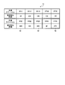
ここで、図11を用いて作業ステーションの限定について説明する。図11は、部材切れ時間の一例を示す図である。図11に示す表41は、図7の状況における各作業ステーションの部材切れ時間を示す。また、各作業ステーションにおける1製品あたりの部材の使用数は、作業ステーションST14が3個、作業ステーションST25が2個、他の作業ステーションがそれぞれ1個であるとする。このとき、基準時間を設定しない場合には、10個の作業ステーションに供給する組合せは、10!=3,628,800通りとなり、厳密解を求めるには時間を要する。
これに対し、基準時間を240秒とすると、領域42に示す3つの作業ステーションST21、ST23、ST25を対象から除くことができる。このため、対象作業ステーションは、7個に限定される。つまり、基準時間を240秒と設定した場合には、7個の作業ステーションに供給する組合せは、7!=5040通りとなり、厳密解を短時間で求めることができる。
次に、実施例2の部材供給システム2の動作について説明する。図12は、実施例2の部材供給処理の一例を示すフローチャートである。以下の説明では、ステップS1~S3、S5~S8の処理は、実施例1と同様であるので、その説明を省略する。
情報処理装置200は、ステップS3の処理に続いて、次の処理を実行する。探索部233には、予測部132から探索指示が入力される。探索部233は、探索指示が入力されると、ステーション状況記憶部123を参照し、予め設定した基準時間未満の作業ステーションを選択する。すなわち、探索部233は、部材供給の対象作業ステーションを限定する(ステップS21)。
探索部233は、選択した作業ステーションの部材切れ時間と、対応する移動時間および移動距離とに基づいて、部材供給経路を探索する(ステップS22)。すなわち、探索部233は、選択した作業ステーションで部材切れを起こさない経路を抽出する。探索部233は、抽出した経路のうち、選択した各作業ステーション間の移動距離に基づいて、経路全体の移動距離が最短となる経路を選択する。探索部233は、選択した経路を指示部134に出力し、ステップS5に進む。これにより、情報処理装置200は、短時間で経路探索の厳密解を求めることができる。また、情報処理装置200は、次の指示までの待ち時間を短縮できる。
このように、情報処理装置200は、予測した部材切れ時間が、予め設定した基準時間未満である各作業ステーションに対して部材を供給する経路を探索する。その結果、短時間で経路探索の厳密解を求めることができる。
なお、上記各実施例では、部材供給者5が台車6に部材を積載して、各作業ステーションに部材を供給したが、これに限定されない。例えば、無人搬送車に端末装置20を設置し、端末装置20が受信した指示の情報に基づいて、無人搬送車が次に向かう作業ステーションを決定するようにしてもよい。これにより、無人搬送車を動かすエネルギーを削減できる。
また、上記各実施例では、情報処理装置100または200の各機能部を1つの装置としたが、これに限定されない。例えば、情報処理装置100または200の各機能部をSaaS等のクラウドコンピューティングサービスを用いて構成し、処理能力を高めることで、より高速に経路探索を行ってもよい。また、情報処理装置100または200の各機能部をSaaS等のクラウドコンピューティングサービスを用いて構成し、同一工場内の複数の生産ユニットや、異なる工場の生産ユニットに対して、それぞれ効率的な部材供給経路を指示するようにしてもよい。
また、上記各実施例では、準備ステーション7における台車6への部材の積載を含む準備時間を省略したが、台車6の積載量を考慮して、準備時間を含めてもよいし、経路の途中で一旦準備ステーション7に部材を補充しに戻るようにしてもよい。
また、上記では、多品種少量生産での課題に着目したが、他にも、実際の動きとシミュレーションの動きとの差異、組立作業者8の作業の習熟による作業時間の短縮等によっても、部材供給者5の出発時点での経路やタイミングが最適とならない場合がある。このような場合であっても、上記各実施例では、状況に応じて効率的に部材を供給できる。
また、図示した各部の各構成要素は、必ずしも物理的に図示の如く構成されていることを要しない。すなわち、各部の分散・統合の具体的形態は図示のものに限られず、その全部または一部を、各種の負荷や使用状況等に応じて、任意の単位で機能的または物理的に分散・統合して構成することができる。例えば、探索部133と指示部134とを統合してもよい。また、図示した各処理は、上記の順番に限定されるものではなく、処理内容を矛盾させない範囲において、同時に実施してもよく、順序を入れ替えて実施してもよい。
さらに、各装置で行われる各種処理機能は、CPU(又はMPU、MCU(Micro Controller Unit)等のマイクロ・コンピュータ)上で、その全部または任意の一部を実行するようにしてもよい。また、各種処理機能は、CPU(またはMPU、MCU等のマイクロ・コンピュータ)で解析実行されるプログラム上、またはワイヤードロジックによるハードウェア上で、その全部又は任意の一部を実行するようにしてもよいことは言うまでもない。
ところで、上記の実施例で説明した各種の処理は、予め用意されたプログラムをコンピュータで実行することで実現できる。そこで、以下では、上記の実施例と同様の機能を有するプログラムを実行するコンピュータの一例を説明する。図13は、部材供給プログラムを実行するコンピュータの一例を示す図である。
図13に示すように、コンピュータ300は、各種演算処理を実行するCPU301と、データ入力を受け付ける入力装置302と、モニタ303とを有する。また、コンピュータ300は、記憶媒体からプログラム等を読み取る媒体読取装置304と、各種装置と接続するためのインタフェース装置305と、他の情報処理装置等と有線または無線により接続するための通信装置306とを有する。また、コンピュータ300は、各種情報を一時記憶するRAM307と、ハードディスク装置308とを有する。また、各装置301~308は、バス309に接続される。
ハードディスク装置308には、図1に示した取得部131、予測部132、探索部133および指示部134の各処理部と同様の機能を有する部材供給プログラムが記憶される。また、ハードディスク装置308には、移動時間記憶部121、移動距離記憶部122、ステーション状況記憶部123、および、部材供給プログラムを実現するための各種データが記憶される。入力装置302は、例えば、コンピュータ300の管理者から操作情報、管理情報等の各種情報の入力を受け付ける。モニタ303は、例えば、コンピュータ300の管理者に対して表示画面等の各種画面を表示する。インタフェース装置305は、例えば印刷装置等が接続される。通信装置306は、例えば、図1に示した通信部110と同様の機能を有しネットワークNと接続され、計測装置10および端末装置20と各種情報をやりとりする。
CPU301は、ハードディスク装置308に記憶された各プログラムを読み出して、RAM307に展開して実行することで、各種の処理を行う。また、これらのプログラムは、コンピュータ300を図1に示した取得部131、予測部132、探索部133および指示部134として機能させることができる。
なお、上記の部材供給プログラムは、必ずしもハードディスク装置308に記憶されている必要はない。例えば、コンピュータ300が読み取り可能な記憶媒体に記憶されたプログラムを、コンピュータ300が読み出して実行するようにしてもよい。コンピュータ300が読み取り可能な記憶媒体は、例えば、CD-ROMやDVDディスク、USB(Universal Serial Bus)メモリ等の可搬型記録媒体、フラッシュメモリ等の半導体メモリ、ハードディスクドライブ等が対応する。また、公衆回線、インターネット、LAN等に接続された装置にこの部材供給プログラムを記憶させておき、コンピュータ300がこれらから部材供給プログラムを読み出して実行するようにしてもよい。
1,2 部材供給システム
10 計測装置
11 通信部
12 計測部
13 制御部
20 端末装置
21 通信部
22 表示部
23 制御部
100,200 情報処理装置
110 通信部
120 記憶部
121 移動時間記憶部
122 移動距離記憶部
123 ステーション状況記憶部
130,230 制御部
131 取得部
132 予測部
133,233 探索部
134 指示部
N ネットワーク
10 計測装置
11 通信部
12 計測部
13 制御部
20 端末装置
21 通信部
22 表示部
23 制御部
100,200 情報処理装置
110 通信部
120 記憶部
121 移動時間記憶部
122 移動距離記憶部
123 ステーション状況記憶部
130,230 制御部
131 取得部
132 予測部
133,233 探索部
134 指示部
N ネットワーク
Claims (9)
- 作業工程における各作業が行われる各作業ステーションに部材を運搬する台車が、前記部材を準備する準備ステーションから出発する場合、または、ある作業ステーションに対して前記部材の供給が完了した場合に、前記各作業ステーションから、それぞれの作業ステーションでの作業に用いる部材について残りの部材数を取得し、
取得した前記作業ステーションごとの前記部材数に基づいて、前記各作業ステーションの部材切れ時間を予測し、
前記作業ステーション間の移動時間および移動距離と、予測した前記部材切れ時間とに基づいて、前記各作業ステーションに対して部材を供給する経路を探索し、
探索した前記経路に基づいて、次に部材を供給する前記作業ステーションを指示する、
処理をコンピュータが実行することを特徴とする部材供給方法。 - 前記探索する処理は、予測した前記部材切れ時間が、予め設定した基準時間未満である前記各作業ステーションに対して部材を供給する経路を探索する、
ことを特徴とする請求項1に記載の部材供給方法。 - 前記予測する処理は、現在時刻から所定時間前までの前記部材数の時間推移を直線近似して、前記部材切れ時間を予測する、
ことを特徴とする請求項1に記載の部材供給方法。 - 作業工程における各作業が行われる各作業ステーションに部材を運搬する台車が、前記部材を準備する準備ステーションから出発する場合、または、ある作業ステーションに対して前記部材の供給が完了した場合に、前記各作業ステーションから、それぞれの作業ステーションでの作業に用いる部材について残りの部材数を取得し、
取得した前記作業ステーションごとの前記部材数に基づいて、前記各作業ステーションの部材切れ時間を予測し、
前記作業ステーション間の移動時間および移動距離と、予測した前記部材切れ時間とに基づいて、前記各作業ステーションに対して部材を供給する経路を探索し、
探索した前記経路に基づいて、次に部材を供給する前記作業ステーションを指示する、
処理をコンピュータに実行させることを特徴とする部材供給プログラム。 - 前記探索する処理は、予測した前記部材切れ時間が、予め設定した基準時間未満である前記各作業ステーションに対して部材を供給する経路を探索する、
ことを特徴とする請求項4に記載の部材供給プログラム。 - 前記予測する処理は、現在時刻から所定時間前までの前記部材数の時間推移を直線近似して、前記部材切れ時間を予測する、
ことを特徴とする請求項4に記載の部材供給プログラム。 - 計測装置と、情報処理装置と、端末装置とを有する部材供給システムであって、
前記計測装置は、
作業工程における各作業が行われる各作業ステーションでの作業に用いる部材について残りの部材数を計測する計測部と、
計測された前記部材数を前記情報処理装置に送信する通信部と、を有し、
前記情報処理装置は、
前記各作業ステーションに部材を運搬する台車が、前記部材を準備する準備ステーションから出発する場合、または、ある作業ステーションに対して前記部材の供給が完了した場合に、前記各作業ステーションの前記計測装置から、それぞれの作業ステーションでの前記部材数を取得する取得部と、
取得された前記作業ステーションごとの前記部材数に基づいて、前記各作業ステーションの部材切れ時間を予測する予測部と、
前記作業ステーション間の移動時間および移動距離と、予測された前記部材切れ時間とに基づいて、前記各作業ステーションに対して部材を供給する経路を探索する探索部と、
探索された前記経路に基づいて、次に部材を供給する前記作業ステーションを指示する指示部と、
前記指示の情報を前記端末装置に送信する通信部と、を有し、
前記端末装置は、
前記情報処理装置から前記指示の情報を受信する通信部と、
受信された前記指示の情報を表示する表示制御部と、
を有することを特徴とする部材供給システム。 - 前記探索部は、予測された前記部材切れ時間が、予め設定した基準時間未満である前記各作業ステーションに対して部材を供給する経路を探索する、
ことを特徴とする請求項7に記載の部材供給システム。 - 前記予測部は、現在時刻から所定時間前までの前記部材数の時間推移を直線近似して、前記部材切れ時間を予測する、
ことを特徴とする請求項7に記載の部材供給システム。
Priority Applications (2)
| Application Number | Priority Date | Filing Date | Title |
|---|---|---|---|
| PCT/JP2016/063513 WO2017187645A1 (ja) | 2016-04-28 | 2016-04-28 | 部材供給方法、部材供給プログラムおよび部材供給システム |
| JP2018514092A JP6835073B2 (ja) | 2016-04-28 | 2016-04-28 | 部材供給方法、部材供給プログラムおよび部材供給システム |
Applications Claiming Priority (1)
| Application Number | Priority Date | Filing Date | Title |
|---|---|---|---|
| PCT/JP2016/063513 WO2017187645A1 (ja) | 2016-04-28 | 2016-04-28 | 部材供給方法、部材供給プログラムおよび部材供給システム |
Publications (1)
| Publication Number | Publication Date |
|---|---|
| WO2017187645A1 true WO2017187645A1 (ja) | 2017-11-02 |
Family
ID=60161321
Family Applications (1)
| Application Number | Title | Priority Date | Filing Date |
|---|---|---|---|
| PCT/JP2016/063513 Ceased WO2017187645A1 (ja) | 2016-04-28 | 2016-04-28 | 部材供給方法、部材供給プログラムおよび部材供給システム |
Country Status (2)
| Country | Link |
|---|---|
| JP (1) | JP6835073B2 (ja) |
| WO (1) | WO2017187645A1 (ja) |
Cited By (3)
| Publication number | Priority date | Publication date | Assignee | Title |
|---|---|---|---|---|
| CN113183155A (zh) * | 2021-05-12 | 2021-07-30 | 广州极飞科技股份有限公司 | 一种作业机器人的补给方法、装置及系统 |
| JP2022090515A (ja) * | 2020-12-07 | 2022-06-17 | サイレックス・テクノロジー株式会社 | 通信装置、通信装置の制御方法及び通信システム |
| JP2024011019A (ja) * | 2022-07-13 | 2024-01-25 | ヤマハ発動機株式会社 | 生産管理システムおよび生産管理方法 |
Citations (2)
| Publication number | Priority date | Publication date | Assignee | Title |
|---|---|---|---|---|
| JPH05186004A (ja) * | 1992-01-13 | 1993-07-27 | Nissan Motor Co Ltd | 部品の補給方法 |
| JPH07175504A (ja) * | 1993-12-20 | 1995-07-14 | Atr Ningen Joho Tsushin Kenkyusho:Kk | 配送問題における最適な配車と配送順序の探索装置および探索方法 |
Family Cites Families (2)
| Publication number | Priority date | Publication date | Assignee | Title |
|---|---|---|---|---|
| JP5000818B2 (ja) * | 2001-08-28 | 2012-08-15 | パナソニック株式会社 | メッセージ通知システム |
| JP2004207335A (ja) * | 2002-12-24 | 2004-07-22 | Renesas Technology Corp | 搬送システムの制御装置 |
-
2016
- 2016-04-28 WO PCT/JP2016/063513 patent/WO2017187645A1/ja not_active Ceased
- 2016-04-28 JP JP2018514092A patent/JP6835073B2/ja not_active Expired - Fee Related
Patent Citations (2)
| Publication number | Priority date | Publication date | Assignee | Title |
|---|---|---|---|---|
| JPH05186004A (ja) * | 1992-01-13 | 1993-07-27 | Nissan Motor Co Ltd | 部品の補給方法 |
| JPH07175504A (ja) * | 1993-12-20 | 1995-07-14 | Atr Ningen Joho Tsushin Kenkyusho:Kk | 配送問題における最適な配車と配送順序の探索装置および探索方法 |
Cited By (5)
| Publication number | Priority date | Publication date | Assignee | Title |
|---|---|---|---|---|
| JP2022090515A (ja) * | 2020-12-07 | 2022-06-17 | サイレックス・テクノロジー株式会社 | 通信装置、通信装置の制御方法及び通信システム |
| JP7648076B2 (ja) | 2020-12-07 | 2025-03-18 | サイレックス・テクノロジー株式会社 | 通信システム及び通信方法 |
| CN113183155A (zh) * | 2021-05-12 | 2021-07-30 | 广州极飞科技股份有限公司 | 一种作业机器人的补给方法、装置及系统 |
| JP2024011019A (ja) * | 2022-07-13 | 2024-01-25 | ヤマハ発動機株式会社 | 生産管理システムおよび生産管理方法 |
| JP7817101B2 (ja) | 2022-07-13 | 2026-02-18 | ヤマハ発動機株式会社 | 生産管理システムおよび生産管理方法 |
Also Published As
| Publication number | Publication date |
|---|---|
| JP6835073B2 (ja) | 2021-02-24 |
| JPWO2017187645A1 (ja) | 2018-11-22 |
Similar Documents
| Publication | Publication Date | Title |
|---|---|---|
| EP3605405A1 (en) | Server device, trained model providing program, trained model providing method, and trained model providing system | |
| Kuo et al. | Industry 4.0 enabling manufacturing competitiveness: Delivery performance improvement based on theory of constraints | |
| JP2011047925A5 (ja) | ||
| US20160283895A1 (en) | Plan determination method, computer-readable recording medium storing plan determination program, and plan determination apparatus | |
| US10289099B2 (en) | Operation order system | |
| JP6835073B2 (ja) | 部材供給方法、部材供給プログラムおよび部材供給システム | |
| JP7564234B2 (ja) | 工具搬送システム、工具搬送システムの制御方法、および、工具搬送システムの制御プログラム | |
| KR102462618B1 (ko) | 퀵 배송 서비스를 위한 배송경로정보 제공 방법 및 장치 | |
| US20150277693A1 (en) | Production plan preparation support method and production plan preparation support apparatus | |
| JP6664564B1 (ja) | 情報技術活用評価装置、情報技術活用評価システムおよび情報技術活用評価方法 | |
| Lichtenstern et al. | Data-based digital twin of an automated guided vehicle system | |
| CN101652727A (zh) | 作业指示系统、作业指示方法、作业指示程序、存储了作业指示程序的计算机可读取的存储介质以及作业指示装置 | |
| JP6409268B2 (ja) | 生産管理方法及び生産管理装置 | |
| JP7172157B2 (ja) | 情報処理方法および情報処理装置 | |
| US9990178B2 (en) | Solving a combinatorial problem using a quality metric value of a characteristic solution thereof | |
| JP7470608B2 (ja) | 作業改善支援装置、作業改善支援システム | |
| EP4095772A1 (en) | Optimization of a production system | |
| JP6621649B2 (ja) | 情報端末およびサーバ | |
| JP2018136823A (ja) | 作業支援システム、作業支援方法及びプログラム | |
| EP3690588B1 (en) | Information processing device, information processing method, and program | |
| EP2704090A1 (en) | Goods transportation simulation device, goods transportation plan creation device, goods storage design support device, goods transportation simulation method, goods transportation plan creation method, goods storage design support method and program | |
| JP6832803B2 (ja) | 作業干渉削減システム、作業干渉削減装置、作業干渉削減方法及びプログラム | |
| KR20240115155A (ko) | 게이트웨이가 탑재된 배송 차량과 통신을 수행하는 시스템 | |
| EP4630964A1 (en) | System for process flow templating and duplication of tasks within material flow automation | |
| JPWO2018189851A1 (ja) | 搬送作業制御装置、システム、方法およびプログラム |
Legal Events
| Date | Code | Title | Description |
|---|---|---|---|
| WWE | Wipo information: entry into national phase |
Ref document number: 2018514092 Country of ref document: JP |
|
| NENP | Non-entry into the national phase |
Ref country code: DE |
|
| 121 | Ep: the epo has been informed by wipo that ep was designated in this application |
Ref document number: 16900515 Country of ref document: EP Kind code of ref document: A1 |
|
| 122 | Ep: pct application non-entry in european phase |
Ref document number: 16900515 Country of ref document: EP Kind code of ref document: A1 |