WO2017187594A1 - Belt conveyor cleaning device - Google Patents
Belt conveyor cleaning device Download PDFInfo
- Publication number
- WO2017187594A1 WO2017187594A1 PCT/JP2016/063342 JP2016063342W WO2017187594A1 WO 2017187594 A1 WO2017187594 A1 WO 2017187594A1 JP 2016063342 W JP2016063342 W JP 2016063342W WO 2017187594 A1 WO2017187594 A1 WO 2017187594A1
- Authority
- WO
- WIPO (PCT)
- Prior art keywords
- housing
- belt
- belt conveyor
- cleaning
- discharge nozzle
- Prior art date
Links
Images


Classifications
-
- B—PERFORMING OPERATIONS; TRANSPORTING
- B65—CONVEYING; PACKING; STORING; HANDLING THIN OR FILAMENTARY MATERIAL
- B65G—TRANSPORT OR STORAGE DEVICES, e.g. CONVEYORS FOR LOADING OR TIPPING, SHOP CONVEYOR SYSTEMS OR PNEUMATIC TUBE CONVEYORS
- B65G45/00—Lubricating, cleaning, or clearing devices
- B65G45/10—Cleaning devices
- B65G45/22—Cleaning devices comprising fluid applying means
Abstract
Provided is a belt conveyor cleaning device comprising: a housing 2 disposed facing from below the belt transport surface 5 of an endless belt conveyor 3 and having formed on the upper side thereof an opening 7 facing the belt transport surface 5; at least one cleaning nozzle 15 provided within the housing and capable of jetting cleaning liquid toward the opening; and a separation member 13 provided around the opening of the housing and covering the gap between the belt transport surface and the periphery of the opening of the housing when the belt transport surface passes over the opening. The belt conveyor cleaning device also comprises a discharge nozzle 33 directed toward the position where the jetting opening 41 thereof faces a water discharge opening 27. The jetting of fluid from the jetting opening of the discharge nozzle generates negative pressure within the housing when the belt transport surface passes over the opening of the housing.
Description
本発明は、無端ベルトコンベアの搬送面を洗浄する装置に関する。
The present invention relates to an apparatus for cleaning the transport surface of an endless belt conveyor.
被搬送物を無端ベルトコンベアで搬送する場合、被搬送物によっては無端ベルトの搬送面を洗浄する必要がある。従来、無端ベルトの搬送面を洗浄する方法として、搬送面がコンベアの下側に来たときに洗浄ノズルから洗浄液を搬送面に向けて噴射して洗浄していた。しかし搬送面、特に下向きの搬送面に向けて洗浄液を噴射することで洗浄液は周囲に飛び散るため、周囲の清掃や水拭きなどの作業をすることが必要であった。
When transporting a transported object with an endless belt conveyor, it is necessary to clean the transport surface of the endless belt depending on the transported object. Conventionally, as a method for cleaning the transport surface of the endless belt, the cleaning liquid is sprayed from the cleaning nozzle toward the transport surface when the transport surface comes to the lower side of the conveyor. However, since the cleaning liquid is scattered around by spraying the cleaning liquid toward the transport surface, particularly the downward transport surface, it is necessary to perform operations such as cleaning the surroundings and wiping with water.
これに関連して従来、クリーニングチャンバに洗浄ノズルを設け、洗浄ノズルから噴射される洗浄液で床面等を洗浄し、洗浄後の洗浄液を別のノズルから吸引する技術が開発されている(特許文献1)。
In relation to this, a technology has been developed in which a cleaning nozzle is provided in a cleaning chamber, the floor surface or the like is cleaned with a cleaning liquid sprayed from the cleaning nozzle, and the cleaned cleaning liquid is sucked from another nozzle (Patent Document). 1).
また特許文献2には、移動するコンベアベルトで粉体を含む被輸送物を輸送する場合に、コンベアベルトの戻り側の表面に散水してコンベアベルトの表面を一様に濡らす技術が公開されている。
Patent Document 2 discloses a technique for uniformly wetting the surface of the conveyor belt by spraying water on the return side surface of the conveyor belt when transporting an object to be transported including powder on the moving conveyor belt. Yes.
更に特許文献3には、エンドレスベルトのリターン部両側に設置されるオゾン水噴霧器をエンドレスベルトに僅かな隙間をあけて近接している囲いと、この囲いとエンドレスベルトの隙間からオゾンを含むエアが漏れないように囲い内のエアを吸い出す排気配管を備える技術が公開されている。
Furthermore, Patent Document 3 discloses that an ozone water sprayer installed on both sides of the return portion of the endless belt is adjacent to the endless belt with a slight gap, and air containing ozone from the gap between the enclosure and the endless belt. A technology that includes an exhaust pipe that sucks out air in the enclosure so as not to leak is disclosed.
しかし搬送面がコンベアの下側に来たときに洗浄ノズルから洗浄液を搬送面に向けて噴射する方法では、特許文献1に示す技術によっても、一部の洗浄液は別のノズルから排出されるものの、多くの洗浄液が周囲に飛び散るという問題点は解決できない。
However, in the method in which the cleaning liquid is sprayed from the cleaning nozzle toward the transport surface when the transport surface comes to the lower side of the conveyor, even with the technique shown in Patent Document 1, a part of the cleaning liquid is discharged from another nozzle. The problem that a lot of cleaning liquid scatters around cannot be solved.
また洗浄ノズルとは別に吸引ノズルを設け洗浄液を吸引ノズルから吸引する場合、装置が複雑になる。また、チャンバ内の負圧が大きすぎると搬送面がチャンバの開放面に吸着してしまい、無端ベルトコンベアの駆動に支障を来したり、搬送面の変形や損傷の原因にもなりかねない。
Also, when a suction nozzle is provided separately from the cleaning nozzle and the cleaning liquid is sucked from the suction nozzle, the apparatus becomes complicated. In addition, if the negative pressure in the chamber is too large, the transport surface is attracted to the open surface of the chamber, which may hinder the driving of the endless belt conveyor and may cause deformation or damage of the transport surface.
本発明は上記問題に鑑みてなされたもので、その目的は、洗浄ノズルからの洗浄液が周囲に飛び散ることを防止し、無端ベルトコンベアの駆動に支障を来すことなく洗浄可能な簡易なベルトコンベア洗浄装置を提供することである。
The present invention has been made in view of the above problems, and an object of the present invention is to provide a simple belt conveyor that prevents the cleaning liquid from the cleaning nozzle from splashing around and can be cleaned without hindering driving of the endless belt conveyor. It is to provide a cleaning device.
本発明のベルトコンベア洗浄装置の一形態は、無端ベルトコンベアのベルト搬送面に下側から臨むように配置され、上側にベルト搬送面に臨む開放部が形成されるハウジングと、ハウジング内に設けられ、開放部方向へ洗浄液を噴射可能な少なくとも1つの洗浄ノズルと、ハウジングの開放部の周囲に設けられ、開放部の上をベルト搬送面が通過するときにベルト搬送面とハウジングの開放部の周囲との間を覆う、隔離部材と、ハウジングの下方に排液口を有する排液管と、噴射口を有し、噴射口が排液管の排液口に臨む位置に設けられる排出ノズルとを備え、排出ノズルの噴射口から流体が噴出することで、ハウジングの開放部の上をベルト搬送面が通過するときにハウジング内に負圧を生じさせることを特徴とするものである。
One form of the belt conveyor cleaning device of the present invention is disposed so as to face the belt conveyance surface of the endless belt conveyor from the lower side, and is provided in the housing with an opening formed on the upper side facing the belt conveyance surface. , At least one cleaning nozzle capable of spraying the cleaning liquid in the direction of the open portion, and provided around the open portion of the housing, and when the belt transfer surface passes over the open portion, around the belt transfer surface and the open portion of the housing A separating member, a drainage pipe having a drainage port below the housing, and a discharge nozzle provided at a position where the jetting port faces the drainage port of the drainage pipe. And a negative pressure is generated in the housing when the belt conveying surface passes over the open portion of the housing by ejecting fluid from the ejection port of the discharge nozzle.
本形態によれば、ハウジングの開放部の周囲に設けられた隔離部材が、開放部の上をベルト搬送面が通過するときにベルト搬送面とハウジングの開放部の周囲との間を覆い、ハウジング内を実質的に閉鎖空間にする。またハウジングの開放部が実質的に閉鎖されている状態で、排出ノズルの噴射口から流体が噴出することで、ハウジング内の空気を一緒に引き込んで外部へ出そうとする作用が働くため、ハウジング内に負圧が生じる。この負圧により、洗浄液が周囲に飛び散ることがさらに防止され、また洗浄ノズルから供給された洗浄液は排液管内へ導かれるため、洗浄液を排出することができる。
According to this embodiment, the separating member provided around the open portion of the housing covers the space between the belt transport surface and the periphery of the open portion of the housing when the belt transport surface passes over the open portion. The interior is substantially closed. In addition, when the fluid is ejected from the ejection port of the discharge nozzle while the open part of the housing is substantially closed, the action of drawing the air in the housing together and exiting to the outside works. Negative pressure is generated inside. This negative pressure further prevents the cleaning liquid from splashing around, and the cleaning liquid supplied from the cleaning nozzle is guided into the drainage pipe, so that the cleaning liquid can be discharged.
また本発明のベルトコンベア洗浄装置の第2の形態では、第1の形態に加え、排出ノズルから噴射される流体と洗浄液は水であり、排出ノズルへの水の供給は、洗浄ノズルへの水の供給配管から分岐した配管を介して行われてもよい。
Further, in the second embodiment of the belt conveyor cleaning device of the present invention, in addition to the first embodiment, the fluid and the cleaning liquid ejected from the discharge nozzle are water, and the water supply to the discharge nozzle is the water to the cleaning nozzle. It may be performed via a pipe branched from the supply pipe.
本形態によれば、洗浄液である水は配管を介して洗浄ノズルへ供給されるが、この配管の途中から排出ノズルへ水を供給する配管を分岐させる。従って排出ノズル専用の配管系を新たに別に設ける必要がなく、途中までは洗浄ノズルへの配管を利用できるので、経済的で且つ省スペースな構成とすることができる。
According to this embodiment, the water as the cleaning liquid is supplied to the cleaning nozzle through the pipe, and the pipe for supplying water to the discharge nozzle is branched from the middle of the pipe. Therefore, there is no need to newly provide a separate piping system dedicated to the discharge nozzle, and the piping to the cleaning nozzle can be used up to the middle, so that an economical and space-saving configuration can be achieved.
また本発明のベルトコンベア洗浄装置の第3の形態では、第1または第2の形態に加え、隔離部材は、ブラシであってもよい。排出ノズルの噴射口からの流体の噴出によりハウジング内が負圧になったとき、ブラシの隙間から外部の空気が僅かにハウジング内に供給されるから、ハウジング内の負圧をある程度を和らげて、ハウジングの開放部にベルト搬送面がぴったり密着してベルト搬送面に移動に支障を来すことを防止できる。
In the third embodiment of the belt conveyor cleaning device of the present invention, in addition to the first or second embodiment, the isolation member may be a brush. When the inside of the housing becomes negative pressure due to the ejection of the fluid from the ejection port of the discharge nozzle, external air is slightly supplied from the gap of the brush into the housing, so the negative pressure in the housing is moderated to some extent, It is possible to prevent the belt conveyance surface from coming into close contact with the open portion of the housing and hindering movement on the belt conveyance surface.
また本発明のベルトコンベア洗浄装置の第4の形態では、第1から第3の形態に加え、隔離部材は、開放部の少なくともベルト搬送面の進行方向上流側のほぼ半分に設けられるブラシと、開放部のベルト搬送面の進行方向下流側のほぼ半分に設けられる液切り部とから構成され、液切り部の上端はベルト搬送面に接触してベルト搬送面に付着している洗浄液を液切りしてハウジング内に落とすものでもよい。
Further, in the fourth embodiment of the belt conveyor cleaning device of the present invention, in addition to the first to third embodiments, the separating member includes a brush provided on substantially half of the opening portion on the upstream side in the traveling direction of the belt conveyance surface, The upper part of the liquid drainage part is in contact with the belt conveyance surface and drains the cleaning liquid adhering to the belt conveyance surface. Then, it may be dropped into the housing.
本形態によれば、開放部の少なくともベルト搬送面の進行方向上流側のほぼ半分に設けられるブラシが、ハウジングと外部との空気の流通を一部遮断してハウジング内を負圧に維持することに貢献するとともに、洗浄ノズルから噴射された洗浄液およびベルト搬送面に当たり反射した洗浄液がハウジングの外部へ飛び散ることを防止する。また開放部のベルト搬送面の進行方向下流側のほぼ半分に設けられる液切り部の上端がベルト搬送面に接触して、ベルト搬送面に付着している洗浄液を液切りしてハウジング内に落として、ベルト搬送面の水分を除去することができる。
According to this embodiment, the brush provided at least approximately half of the opening portion on the upstream side in the traveling direction of the belt conveyance surface partially blocks the air flow between the housing and the outside, and maintains the inside of the housing at a negative pressure. In addition, the cleaning liquid sprayed from the cleaning nozzle and the cleaning liquid reflected on the belt conveying surface are prevented from splashing outside the housing. In addition, the upper end of the liquid drainage portion provided approximately halfway downstream in the direction of travel of the belt conveyance surface of the open part contacts the belt conveyance surface, drains the cleaning liquid adhering to the belt conveyance surface and drops it into the housing. Thus, moisture on the belt conveying surface can be removed.
また本発明のベルトコンベア洗浄装置の第5の形態では、第4の形態に加え、ブラシの一部は液切り部の内側に位置し、液切り部と重なって設けられてもよい。
Further, in the fifth embodiment of the belt conveyor cleaning device of the present invention, in addition to the fourth embodiment, a part of the brush may be located inside the liquid draining portion and provided to overlap the liquid draining portion.
本形態によれば、ブラシの一部が液切り部と重なって設けられた箇所では、ブラシによるベルト搬送面の汚れ掻き落とし作用に加え、液切り部によるベルト搬送面の洗浄液の液切り作用を同時に行うことができる。
According to this embodiment, in the part where the brush partly overlaps with the liquid draining part, in addition to the scraping action of the belt conveying surface by the brush, the liquid draining action of the cleaning liquid on the belt conveying surface by the liquid draining part is performed. Can be done simultaneously.
また本発明のベルトコンベア洗浄装置の第6の形態では、第1から第5のいずれかの形態に加え、排出ノズルの噴射口は排液管の排液口の内部に位置決めされることができる。
Further, in the sixth embodiment of the belt conveyor cleaning device of the present invention, in addition to any one of the first to fifth embodiments, the ejection port of the discharge nozzle can be positioned inside the drain port of the drain pipe. .
本形態によれば、排出ノズルの噴射口から噴射される流体により、ベルヌイの定理により周囲に負圧を生じるが、排出ノズルの噴射口が排液管の排液口の内部に位置することで、狭い排液口内での流速が一層高まり、その分だけ高い負圧を生じることができる。
According to this embodiment, the fluid ejected from the ejection port of the discharge nozzle generates a negative pressure around the Bernoulli's theorem, but the ejection port of the discharge nozzle is located inside the drainage port of the drainage pipe. Further, the flow rate in the narrow drainage port is further increased, and a higher negative pressure can be generated accordingly.
また本発明のベルトコンベア洗浄装置の第7の形態では、第1の形態に加え、ハウジングはその横断面が矩形に形成され、隔離部材は、開放部のベルト搬送面の進行方向上流側に設けられるローラ状ブラシと、開放部のベルト搬送面の進行方向下流側に設けられる液切り部と、矩形のハウジングの両側面を覆う側壁とから構成され、ローラ状ブラシの上部はベルト搬送面に接触し、液切り部の上端はベルト搬送面に接触してベルト搬送面に付着している洗浄液を液切りしてハウジング内に落とすものでもよい。
Further, in the seventh embodiment of the belt conveyor cleaning device of the present invention, in addition to the first embodiment, the housing is formed in a rectangular cross section, and the separating member is provided on the upstream side in the traveling direction of the belt conveyance surface of the open portion. The roller-shaped brush, the liquid draining portion provided on the downstream side of the belt conveying surface in the opening direction, and the side walls covering both side surfaces of the rectangular housing, and the upper part of the roller-shaped brush is in contact with the belt conveying surface Further, the upper end of the liquid draining part may come into contact with the belt conveyance surface to drain the cleaning liquid adhering to the belt conveyance surface and drop it into the housing.
本形態によれば、ローラ状ブラシと、液切り部と、ハウジングの両側面を覆う側壁とにより隔離部材を構成するから、ハウジングと外部との空気の流通を一部遮断してハウジング内を負圧に維持することに貢献するとともに、洗浄ノズルから噴射された洗浄液およびベルト搬送面に当たり反射した洗浄液がハウジングの外部へ飛び散ることを防止する。
According to the present embodiment, the roller-shaped brush, the liquid drainage portion, and the side wall that covers both side surfaces of the housing constitute the separating member. In addition to contributing to maintaining the pressure, the cleaning liquid sprayed from the cleaning nozzle and the cleaning liquid reflected by the belt conveyance surface are prevented from splashing outside the housing.
また本発明のベルトコンベア洗浄装置の第8の形態では、第1から第7のいずれかの形態に加え、ハウジングが無端ベルトコンベアのベルト搬送面の傾斜角と同じ角度で配置できるようにハウジングの傾斜角度を調節可能に支持する角度調節部材を備えていてもよい。
Further, in the eighth embodiment of the belt conveyor cleaning device of the present invention, in addition to any of the first to seventh embodiments, the housing can be arranged at the same angle as the inclination angle of the belt conveying surface of the endless belt conveyor. You may provide the angle adjustment member which supports an inclination angle so that adjustment is possible.
本形態によれば、無端ベルトコンベアの傾斜角度が変わったときに、角度調節部材を調節することでベルトコンベア洗浄装置を無端ベルトコンベアに対して適切な位置に配置することができる。
According to this embodiment, when the inclination angle of the endless belt conveyor is changed, the belt conveyor cleaning device can be arranged at an appropriate position with respect to the endless belt conveyor by adjusting the angle adjusting member.
以下、本発明の実施形態について図面を参照して説明する。以下で説明する図面において、同一の又は相当する構成要素には、同一の符号を付して重複した説明を省略する。以下の説明において「上流」という語は、ベルトコンベアが駆動しているときに搬送面の任意の箇所に着目した場合、該任意の箇所が移動直前に位置していた側を意味し、「下流」という語は、該任意の箇所が移動直後に位置する側を意味することとする。
Hereinafter, embodiments of the present invention will be described with reference to the drawings. In the drawings described below, the same or corresponding components are denoted by the same reference numerals, and redundant description is omitted. In the following description, the term “upstream” means the side where the arbitrary position is located immediately before the movement when attention is paid to an arbitrary position on the conveying surface when the belt conveyor is driven. "Means the side on which the arbitrary location is located immediately after movement.
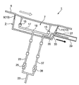
図1は、本発明のベルトコンベア洗浄装置1が適用されている無端ベルトコンベア3を示す斜視図およびベルトコンベア洗浄装置1の配置状態を示す側面図である。本発明のベルトコンベア洗浄装置1は無端ベルトコンベア3のベルト搬送面5に図1(a)中、矢印4で示すように下側から臨むように配置されている。図2に示すように、ベルトコンベア洗浄装置1は全体として断面が円形のハウジング2を備え、ハウジング2の上側には開放部7が形成されている。開放部7は、ベルト搬送面5が下向きに転回した箇所の下流において、ベルト搬送面5に僅かな距離を空けて臨んでいる。
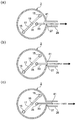
FIG. 1 is a perspective view showing an endless belt conveyor 3 to which the belt conveyor cleaning device 1 of the present invention is applied, and a side view showing an arrangement state of the belt conveyor cleaning device 1. The belt conveyor cleaning device 1 of the present invention is disposed on the belt conveying surface 5 of the endless belt conveyor 3 so as to face from below as indicated by an arrow 4 in FIG. As shown in FIG. 2, the belt conveyor cleaning device 1 includes a housing 2 having a circular cross section as a whole, and an open portion 7 is formed on the upper side of the housing 2. The opening portion 7 faces the belt conveyance surface 5 with a slight distance downstream from the portion where the belt conveyance surface 5 turns downward.
ハウジング2の開放部7の周囲には上流側のほぼ半分に隔離部材13を構成するブラシ9が上向きに設けられている。ブラシ9は、ベルト搬送面5と開放部7との間の間隙を埋めるような長さを有し、ブラシ9の先端はベルト搬送面5に軽く接触している。ブラシ9の毛の密度はハウジング2内で洗浄用の水が飛び散った時に跳ねた水をハウジング2から外部へ出さない程度に密であり、その一方で、後述するようにハウジング2内が負圧になったときに、ハウジング2内の負圧の程度が大きくなり過ぎないように、空気がブラシ9の毛の間からハウジング2内に入ることができるようになっている。
Around the open portion 7 of the housing 2, a brush 9 that constitutes a separating member 13 is provided upward in almost half of the upstream side. The brush 9 has such a length as to fill a gap between the belt conveyance surface 5 and the opening 7, and the tip of the brush 9 is in light contact with the belt conveyance surface 5. The density of the bristles of the brush 9 is so dense that the water splashed when the cleaning water splashes in the housing 2 is not discharged from the housing 2 to the outside. Thus, air can enter the housing 2 from between the bristles of the brush 9 so that the degree of negative pressure in the housing 2 does not become too large.
図2および図3に示すように、ハウジング2の開放部7の周囲の下流側のほぼ半分には、上記ブラシ9とともに隔離部材13を構成する液切り部11が形成されている。液切り部11はゴムで構成されており、ベルト搬送面5と開放部7との間の間隙を埋めるような長さを有する。液切り部11の先端はベルト搬送面5に軽く接触しており、これによりベルト搬送面5が液切り部11の上を通過するとき、後述する洗浄時にベルト搬送面5に付着した水分を掻きとってハウジング2内に落とすことができる。
As shown in FIGS. 2 and 3, a liquid draining portion 11 that constitutes a separating member 13 together with the brush 9 is formed in almost half of the downstream side around the opening portion 7 of the housing 2. The liquid draining part 11 is made of rubber and has a length that fills the gap between the belt conveying surface 5 and the opening part 7. The tip of the liquid draining part 11 is in light contact with the belt conveying surface 5, so that when the belt conveying surface 5 passes over the liquid draining part 11, the water adhering to the belt conveying surface 5 during the cleaning described later is scraped off. It can then be dropped into the housing 2.
このようにブラシ9と液切り部11とにより隔離部材13が構成され、この隔離部材13によりベルト搬送面5と開放部7との間の間隙の全周囲が外部から隔離されて、ハウジング2内で洗浄用の水が飛び散った時に跳ねた水がハウジング2の外部へ出ないようにしている。
In this way, the separating member 13 is constituted by the brush 9 and the liquid draining portion 11, and the entire periphery of the gap between the belt conveying surface 5 and the opening portion 7 is isolated from the outside by the separating member 13, so that the inside of the housing 2 Thus, the water splashed when the washing water splashes is prevented from coming out of the housing 2.
なお図2(b)に示すように、ハウジング2の開放部7の全周囲にブラシ9を設け、更に開放部7の周囲の下流側のほぼ半分であってブラシ9の外側に液切り部11を設けるようにしてもよい。
As shown in FIG. 2B, a brush 9 is provided around the entire open portion 7 of the housing 2, and the liquid draining portion 11 is provided on the outer side of the brush 9 on the downstream side of the open portion 7. May be provided.
図2(a)(b)に示すように、ハウジング2の内部には2つの洗浄ノズル15が設けられている。2つの洗浄ノズル15の各々は、円形のハウジング2の直径方向に延びる水供給管17の両端に設けられ、各洗浄ノズル15は真上よりも若干互いに反対方向に同じ角度で傾いて配置されている。これにより水供給管17から両方の洗浄ノズル15に洗浄液である水が供給されて洗浄ノズル15から水が噴射されるときに、水噴射の勢いの反作用により回転軸19の周囲で矢印21の方向に自由回転できるようになっている。
2A and 2B, two cleaning nozzles 15 are provided inside the housing 2. As shown in FIG. Each of the two cleaning nozzles 15 is provided at both ends of a water supply pipe 17 extending in the diametrical direction of the circular housing 2, and each cleaning nozzle 15 is disposed at an equal angle in a direction slightly opposite to each other from directly above. Yes. As a result, when water as a cleaning liquid is supplied from the water supply pipe 17 to both cleaning nozzles 15 and water is jetted from the washing nozzles 15, the direction of the arrow 21 around the rotary shaft 19 due to the reaction of the momentum of water jetting. Can be freely rotated.
水供給管17は回転軸19の内部に形成された管路に連通しており、更に回転軸19内の管路は図5に示すように水供給メイン配管23に接続されている。水供給メイン配管23にはバルブ25が設けられ、バルブ25の開閉動作により洗浄ノズル15への水の供給と停止が制御される。
The water supply pipe 17 communicates with a pipe formed inside the rotary shaft 19, and the pipe inside the rotary shaft 19 is connected to a water supply main pipe 23 as shown in FIG. The water supply main pipe 23 is provided with a valve 25, and the supply and stop of water to the cleaning nozzle 15 are controlled by opening and closing the valve 25.
図2(a)(b)に示すようにハウジング2の内部には排液口に相当する排水口27が形成されている。2つの洗浄ノズル15から噴射された水はハウジング2内に落下し、排水口27からハウジング2に一体形成される排水管29を通って排水される。洗浄後の水は排水管29を介して外部へ排出されるか、図示しないリサイクル機構で清浄な水に処理され、その後リサイクルされる。排水口の位置は洗浄装置をコンベアに取り付けた際に下部、特に最下部となる位置が好ましい。
As shown in FIGS. 2A and 2B, a drain port 27 corresponding to a drain port is formed in the housing 2. The water sprayed from the two washing nozzles 15 falls into the housing 2 and is drained from the drain port 27 through the drain pipe 29 formed integrally with the housing 2. The washed water is discharged to the outside through the drain pipe 29 or treated with clean water by a recycle mechanism (not shown) and then recycled. The position of the drain outlet is preferably the lower part, particularly the lowermost part when the cleaning device is attached to the conveyor.
また図2(a)(b)、図5に示すようにハウジング2の内部には排出ノズル33が設けられている。排出ノズル33からは水が噴射されるようになっており、この水は供給管35を介して供給される。図5に示すように供給管35は、水供給メイン配管23から分岐される負圧供給用配管37に接続されている。負圧供給用配管37にはバルブ38が設けられ、バルブ38の開閉動作により排出ノズル33への水の供給と停止が制御される。上述のように2つの洗浄ノズル15と排出ノズル33への水供給元は、同じ水供給メイン配管23である。このような構成を採用することにより、洗浄ノズル15と排出ノズル33の両方へそれぞれ水を供給する配管をそれぞれ敷設する手間が省けるので、経済的、省スペース的に有利であるとともに、洗浄ノズル15しか存在しない既存の洗浄装置に後付けで排出ノズル33を設け、やはり後付けで負圧供給用配管37を容易に設けることができる。
Further, as shown in FIGS. 2A and 2B and FIG. 5, a discharge nozzle 33 is provided inside the housing 2. Water is jetted from the discharge nozzle 33, and this water is supplied through the supply pipe 35. As shown in FIG. 5, the supply pipe 35 is connected to a negative pressure supply pipe 37 branched from the water supply main pipe 23. The negative pressure supply pipe 37 is provided with a valve 38, and the supply and stop of water to the discharge nozzle 33 are controlled by opening and closing operations of the valve 38. As described above, the water supply source to the two cleaning nozzles 15 and the discharge nozzle 33 is the same water supply main pipe 23. By adopting such a configuration, it is possible to save the trouble of laying pipes for supplying water to both the cleaning nozzle 15 and the discharge nozzle 33, which is advantageous in terms of economy and space saving, and the cleaning nozzle 15 However, it is possible to provide the discharge nozzle 33 as a retrofit to an existing cleaning apparatus that exists only, and to easily provide the negative pressure supply pipe 37 as a retrofit.
次に図6を参照しながら排出ノズル33の噴射口41の位置について説明する。本願発明では排出ノズル33の噴射口41から水が外側へ噴射されることにより、ベルヌイの定理によりその部分での流れが他の箇所よりも速くなって負圧を生じる。この負圧はハウジング2の内部まで及び、洗浄ノズル15から噴射された水がベルト搬送面5を洗浄した後、負圧により外に飛び散らないように作用する。
Next, the position of the ejection port 41 of the discharge nozzle 33 will be described with reference to FIG. In the present invention, water is jetted outward from the jet nozzle 41 of the discharge nozzle 33, so that the flow at that portion is faster than the other portions according to Bernoulli's theorem, and negative pressure is generated. This negative pressure reaches the inside of the housing 2 and acts so that the water sprayed from the cleaning nozzle 15 does not scatter outside due to the negative pressure after cleaning the belt conveying surface 5.
このような負圧をハウジング2内に有効に生じさせるために、排出ノズル33の噴射口41の位置は排水管29の排水口27に臨む位置に設けられている。「排水口27に臨む位置」とは、図6(a)に示すように、排出ノズル33の噴射口41が排水口27から少し離れているが、排水口27に近い位置で排水口27側に向いている状態、図6(b)に示すように、排出ノズル33の噴射口41が排水口27とほぼ同じ位置にあるか、あるいは排水口27から少しだけ中に入った状態、および図6(c)に示すように、排出ノズル33の噴射口41が排水口27から完全に中に入った状態のいずれの状態も含む概念である。即ち排出ノズル33の噴射口41からの水の噴射時に、排水口27との位置関係によりハウジング2の内部に負圧を生じることができる全ての位置を含むことができる。図示しないがハウジング2内で生じる負圧を高めるために、排出ノズル33の噴射口41のすぐ下流側の排水管29内にオリフィスを形成するようにしてもよい。
In order to effectively generate such a negative pressure in the housing 2, the position of the injection port 41 of the discharge nozzle 33 is provided at a position facing the drain port 27 of the drain pipe 29. As shown in FIG. 6A, the “position facing the drainage port 27” means that the ejection port 41 of the discharge nozzle 33 is slightly away from the drainage port 27, but at the location near the drainage port 27, the drainage port 27 side. 6B, the outlet 41 of the discharge nozzle 33 is substantially at the same position as the drain 27, or is slightly inserted from the drain 27, and FIG. 6 (c) is a concept including any state in which the injection port 41 of the discharge nozzle 33 is completely inserted into the discharge port 27. That is, it is possible to include all positions where negative pressure can be generated inside the housing 2 due to the positional relationship with the drainage port 27 when water is ejected from the ejection port 41 of the discharge nozzle 33. Although not shown, an orifice may be formed in the drain pipe 29 immediately downstream of the injection port 41 of the discharge nozzle 33 in order to increase the negative pressure generated in the housing 2.
図6(a)から(c)の中で最もハウジング2内に有効な負圧を生じる状態は図6(b)に示すような排出ノズル33の噴射口41と排水口27との位置関係であるが、ハウジング2内での負圧の生じ方は、排出ノズル33の噴射口41からの水の噴射速度や、上述したブラシ9の毛の密度などによっても変わるので、ベルト搬送面5がハウジング2の開放部7に吸着してしまい、無端ベルトコンベアの駆動に支障を来したり、搬送面の変形や損傷の原因にならない程度の負圧がハウジング2に生じるような排出ノズル33の噴射口41と排水口27との位置関係が好ましい。
6 (a) to 6 (c), the state in which the most effective negative pressure is generated in the housing 2 is the positional relationship between the outlet 41 and the outlet 27 of the discharge nozzle 33 as shown in FIG. 6 (b). However, the manner in which the negative pressure is generated in the housing 2 varies depending on the jet speed of water from the jet nozzle 41 of the discharge nozzle 33, the bristle density of the brush 9, and the like. 2 is a suction port of the discharge nozzle 33 that is adsorbed by the open portion 7 of the belt 2 and causes a negative pressure in the housing 2 that does not interfere with the driving of the endless belt conveyor or cause deformation or damage of the transport surface. The positional relationship between 41 and the drain port 27 is preferable.
本願発明のベルトコンベア洗浄装置1は、ハウジング2がベルト搬送面5の傾斜角と同じ角度で配置できるように、図1(b)に示すようにハウジング2の傾斜角度を調節可能に支持する角度調節部材43を備えることが好ましい。角度調節部材43は水平な基台45の上に配置された高さ調整機構47と高さ調整機構47の上に接続される角度調節アタッチメント49を備え、角度調節アタッチメント49がベルトコンベア洗浄装置1に対して角度を調整可能に接続できるようになっている。
The belt conveyor cleaning device 1 of the present invention has an angle that supports the housing 2 in an adjustable manner as shown in FIG. 1B so that the housing 2 can be arranged at the same angle as the inclination of the belt conveying surface 5. The adjustment member 43 is preferably provided. The angle adjusting member 43 includes a height adjusting mechanism 47 disposed on the horizontal base 45 and an angle adjusting attachment 49 connected to the height adjusting mechanism 47, and the angle adjusting attachment 49 is the belt conveyor cleaning device 1. The angle can be connected to be adjustable.
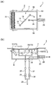
次に本願発明の他の実施形態について図7を参照しながら説明する。上述した図2(a)(b)に示す実施形態ではハウジング2の水平断面が円形であり、ブラシ9を半円状または全円周状に設けている。しかしこのような形態で設けたブラシ9がベルト搬送面5に当接した状態でベルト搬送面5に擦れると、ベルト搬送面5の両端に当接したブラシ9の減りが他の部分に比べて早くなりがちである。図7に示す実施形態はこのような課題を解決するためのものである。
Next, another embodiment of the present invention will be described with reference to FIG. In the embodiment shown in FIGS. 2A and 2B described above, the horizontal section of the housing 2 is circular, and the brush 9 is provided in a semicircular shape or a full circumferential shape. However, if the brush 9 provided in this manner is rubbed against the belt conveyance surface 5 in contact with the belt conveyance surface 5, the reduction of the brush 9 abutting on both ends of the belt conveyance surface 5 is smaller than that of other portions. It tends to be early. The embodiment shown in FIG. 7 is for solving such a problem.
図7に示す実施形態ではハウジング2はその横断面が矩形に形成されており、上方に矩形の開放部7が形成されている。開放部7のベルト搬送面5の進行方向上流側にはローラ状ブラシ51(図7(a)(b)参照)が設けられ、このローラ状ブラシ51は図2(a)(b)に示す実施形態におけるブラシ9と実質的に同じ機能を有する。開放部7のベルト搬送面5の進行方向下流側には、図2(a)(b)に示す実施形態における液切り部11と同じ機能を有する液切り部53を備える(図7(a)(b)参照)。
In the embodiment shown in FIG. 7, the housing 2 has a rectangular cross section, and a rectangular opening 7 is formed above. A roller-shaped brush 51 (see FIGS. 7A and 7B) is provided on the upstream side of the belt conveying surface 5 in the opening portion 7 in the traveling direction, and this roller-shaped brush 51 is shown in FIGS. It has substantially the same function as the brush 9 in the embodiment. A liquid draining portion 53 having the same function as the liquid draining portion 11 in the embodiment shown in FIGS. 2A and 2B is provided on the downstream side in the traveling direction of the belt conveying surface 5 of the opening portion 7 (FIG. 7A). (See (b)).
図7(a)(b)に示すように、矩形の開放部7の両側部にはゴム製の側壁55が設けられている。側壁55はベルト搬送面5と開放部7との間の間隙を埋めるような長さを有し、側壁55の上端はベルト搬送面5に軽く接触している。本実施形態では、ローラ状ブラシ51、液切り部53及び2つの側壁55が隔離部材13を構成し、これら部材により図2(a)に示す実施形態の場合と同様に、ハウジング2内で洗浄用の水が飛び散った時に跳ねた水をハウジング2から外部へ出さないようにしている。なお本実施形態における洗浄ノズル15、排出ノズル33、これらのノズルへの水の供給配管系は図2(a)に示す実施形態の場合と同様であるので説明を省略する。
7A and 7B, rubber side walls 55 are provided on both sides of the rectangular opening 7. The side wall 55 has a length that fills the gap between the belt conveying surface 5 and the opening 7, and the upper end of the side wall 55 is in light contact with the belt conveying surface 5. In the present embodiment, the roller-shaped brush 51, the liquid draining portion 53, and the two side walls 55 constitute the separating member 13, and the members are cleaned in the housing 2 as in the case of the embodiment shown in FIG. The water splashed when the water for use is splashed is prevented from coming out of the housing 2. The cleaning nozzle 15, the discharge nozzle 33, and the water supply piping system to these nozzles in this embodiment are the same as those in the embodiment shown in FIG.
本願発明のベルトコンベア洗浄装置1は以上述べたような構成を備えるものであり、以下その作動について図2(a)に示す実施形態を例にとって説明する。無端ベルトコンベア3で例えばきざみ葉などを目的の場所へ搬送した後、無端ベルトコンベア3は回動してベルト搬送面5が下向きで進行する状態になる。このときベルト搬送面5にはきざみ葉やその破片などが付着していることがあり、ベルト搬送面5を洗浄する必要がある。
The belt conveyor cleaning apparatus 1 of the present invention has the above-described configuration, and the operation thereof will be described below by taking the embodiment shown in FIG. 2A as an example. After the endless belt conveyor 3 conveys, for example, chopped leaves to a target location, the endless belt conveyor 3 rotates and the belt conveying surface 5 advances downward. At this time, knitted leaves or fragments thereof may adhere to the belt conveying surface 5 and the belt conveying surface 5 needs to be cleaned.
ベルト搬送面5がベルトコンベア洗浄装置1の開放部7の上にくると、ブラシ9により付着しているきざみ葉や大きな不純物は掻き落とされる。また排出ノズル33に起因する負圧によりハウジング2内が負圧になっているため、開放部7の上を通過するベルト搬送面5はハウジング2に若干吸い寄せられるようになる。図5においてベルト搬送面5が開放部7の上で若干下側に凹んでいるのは、ベルト搬送面5がハウジング2内に吸い寄せられている状態を若干誇張して示している。これにより隔離部材13とベルト搬送面5との間の間隙は埋まるが、ブラシ9の隙間を通って空気が少しずつハウジング2内に入り込むため、ハウジング2内は必要以上に大きな負圧にはならず、ベルト搬送面5が開放部7に完全に吸着されてベルト搬送面5の駆動に影響を及ぼすようなことはない。
When the belt conveying surface 5 comes on the opening 7 of the belt conveyor cleaning device 1, the kneaded leaves and large impurities attached by the brush 9 are scraped off. Further, since the inside of the housing 2 has a negative pressure due to the negative pressure caused by the discharge nozzle 33, the belt conveying surface 5 passing over the opening 7 is slightly sucked by the housing 2. In FIG. 5, the belt conveyance surface 5 is slightly depressed on the open portion 7 in a slightly exaggerated manner, showing that the belt conveyance surface 5 is sucked into the housing 2. As a result, the gap between the separating member 13 and the belt conveying surface 5 is filled, but air gradually enters the housing 2 through the gap of the brush 9, so that the housing 2 has a negative pressure larger than necessary. Therefore, the belt conveyance surface 5 is not completely attracted to the opening 7 and the drive of the belt conveyance surface 5 is not affected.
開放部7の上を通過するベルト搬送面5には2つの洗浄ノズル15から洗浄液である水が噴射されてベルト搬送面5は水圧により洗浄される。2つのノズル15は上述のように回転するのでベルト搬送面5の全面に水を噴射して洗浄を行う。
The water, which is a cleaning liquid, is jetted from the two cleaning nozzles 15 onto the belt conveyance surface 5 passing over the open portion 7, and the belt conveyance surface 5 is washed with water pressure. Since the two nozzles 15 rotate as described above, cleaning is performed by spraying water over the entire belt conveying surface 5.
洗浄後の水はハウジング2内に落下し、水自体の自重、排出ノズルによる水圧、および排出ノズル33の作用で生じた負圧により排水口27から洗浄水は排出される。洗浄時にベルト搬送面5に付着している水は液切り部11の上をベルト搬送面5が移動するときにハウジング2内に掻き落とされ、同様に排水口27から排出される。
Washed water falls into the housing 2, and the wash water is discharged from the drain outlet 27 by the weight of the water itself, the water pressure by the discharge nozzle, and the negative pressure generated by the action of the discharge nozzle 33. The water adhering to the belt conveying surface 5 at the time of cleaning is scraped off into the housing 2 when the belt conveying surface 5 moves over the liquid draining portion 11 and is similarly discharged from the drain outlet 27.
以上に本発明の実施形態を説明したが、本発明は上記実施形態に限定されるものではなく、特許請求の範囲、及び明細書と図面に記載された技術的思想の範囲内において種々の変形が可能である。なお直接明細書及び図面に記載のない何れの形状や材質であっても、本願発明の作用・効果を奏する以上、本願発明の技術的思想の範囲内である。特に上記実施形態では洗浄液として水を使用しているが、アルコール等、その他の液体でも良い。また上記実施形態では排出ノズルの噴射口から噴射される流体として水を使用しているが、その他の液体でも良いし、空気、炭酸ガスなどの気体であっても良い。
Although the embodiments of the present invention have been described above, the present invention is not limited to the above-described embodiments, and various modifications can be made within the scope of the technical idea described in the claims and the specification and drawings. Is possible. Note that any shape or material not directly described in the specification and drawings is within the scope of the technical idea of the present invention as long as the effects and advantages of the present invention are achieved. In particular, in the above embodiment, water is used as the cleaning liquid, but other liquids such as alcohol may be used. In the above embodiment, water is used as the fluid ejected from the ejection nozzle of the discharge nozzle. However, other liquids or gases such as air and carbon dioxide may be used.
1…ベルトコンベア洗浄装置
2…ハウジング
3…無端ベルトコンベア
4…矢印
5…ベルト搬送面
7…開放部
9…ブラシ
11…液切り部
13…隔離部材
15…洗浄ノズル
17…水供給管
19…回転軸
21…矢印
23…水供給メイン配管
25…バルブ
27…排水口
29…排水管
33…排出ノズル
35…供給管
37…負圧供給用配管
38…バルブ
41…噴射口
43…角度調節部材
45…基台
47…調整機構
49…角度調節アタッチメント
51…ローラ状ブラシ
53…液切り部
55…側壁 DESCRIPTION OFSYMBOLS 1 ... Belt conveyor washing | cleaning apparatus 2 ... Housing 3 ... Endless belt conveyor 4 ... Arrow 5 ... Belt conveyance surface 7 ... Opening part 9 ... Brush 11 ... Liquid draining part 13 ... Isolation member 15 ... Washing nozzle 17 ... Water supply pipe 19 ... Rotation Axis 21 ... Arrow 23 ... Water supply main pipe 25 ... Valve 27 ... Drain port 29 ... Drain pipe 33 ... Drain nozzle 35 ... Supply pipe 37 ... Negative pressure supply pipe 38 ... Valve 41 ... Injection port 43 ... Angle adjusting member 45 ... Base 47 ... Adjustment mechanism 49 ... Angle adjustment attachment 51 ... Roller brush 53 ... Liquid draining part 55 ... Side wall
2…ハウジング
3…無端ベルトコンベア
4…矢印
5…ベルト搬送面
7…開放部
9…ブラシ
11…液切り部
13…隔離部材
15…洗浄ノズル
17…水供給管
19…回転軸
21…矢印
23…水供給メイン配管
25…バルブ
27…排水口
29…排水管
33…排出ノズル
35…供給管
37…負圧供給用配管
38…バルブ
41…噴射口
43…角度調節部材
45…基台
47…調整機構
49…角度調節アタッチメント
51…ローラ状ブラシ
53…液切り部
55…側壁 DESCRIPTION OF
Claims (8)
- 無端ベルトコンベアのベルト搬送面に下側から臨むように配置され、上側に前記ベルト搬送面に臨む開放部が形成されるハウジングと、
前記ハウジング内に設けられ、前記開放部方向へ洗浄液を噴射可能な少なくとも1つの洗浄ノズルと、
前記ハウジングの開放部の周囲に設けられ、前記開放部の上を前記ベルト搬送面が通過するときに前記ベルト搬送面と前記ハウジングの開放部の周囲との間を覆う、隔離部材と、
前記ハウジングの下方に排水口を有する排水管と、
噴射口を有し、前記噴射口が前記排水管の排水口に臨む位置に設けられる排出ノズルとを備え、
前記排出ノズルの噴射口から流体が噴出することで、前記ハウジングの開放部の上を前記ベルト搬送面が通過するときに前記ハウジング内に負圧を生じさせることを特徴とするベルトコンベア洗浄装置。 A housing that is arranged so as to face the belt conveyance surface of the endless belt conveyor from the lower side, and that has an open portion that faces the belt conveyance surface on the upper side;
At least one cleaning nozzle provided in the housing and capable of spraying a cleaning liquid toward the opening portion;
An isolation member provided around the open portion of the housing and covering between the belt transport surface and the periphery of the open portion of the housing when the belt transport surface passes over the open portion;
A drain pipe having a drain outlet below the housing;
And a discharge nozzle provided at a position where the spray port faces the drain port of the drain pipe,
The belt conveyor cleaning device according to claim 1, wherein a fluid is ejected from an ejection port of the discharge nozzle to generate a negative pressure in the housing when the belt conveyance surface passes over an open portion of the housing. - 前記排出ノズルから噴射される流体と前記洗浄液は水であり、前記排出ノズルへの水の供給は、前記洗浄ノズルへの水の供給配管から分岐した配管を介して行われることを特徴とする、請求項1に記載されたベルトコンベア洗浄装置。 The fluid sprayed from the discharge nozzle and the cleaning liquid are water, and the supply of water to the discharge nozzle is performed through a pipe branched from a water supply pipe to the cleaning nozzle. The belt conveyor cleaning apparatus according to claim 1.
- 前記隔離部材は、ブラシであることを特徴とする、請求項1または2に記載されたベルトコンベア洗浄装置。 The belt conveyor cleaning device according to claim 1 or 2, wherein the isolation member is a brush.
- 前記隔離部材は、前記開放部の少なくともベルト搬送面の進行方向上流側のほぼ半分に設けられるブラシと、前記開放部のベルト搬送面の進行方向下流側のほぼ半分に設けられる液切り部とから構成され、前記液切り部の上端は前記ベルト搬送面に接触して前記ベルト搬送面に付着している洗浄液を液切りして前記ハウジング内に落とすことを特徴とする、請求項1、2または3のいずれか一項に記載されたベルトコンベア洗浄装置。 The separating member includes a brush provided at least approximately half on the upstream side in the traveling direction of the belt conveying surface of the opening portion, and a liquid draining portion provided on approximately half the downstream side in the traveling direction of the belt conveying surface of the opening portion. The upper end of the liquid draining part is in contact with the belt conveying surface to drain the cleaning liquid adhering to the belt conveying surface and drop it into the housing. 4. The belt conveyor cleaning device according to any one of 3 above.
- 前記ブラシの一部は前記液切り部の内側に位置し、前記液切り部と重なって設けられることを特徴とする、請求項4に記載されたベルトコンベア洗浄装置。 5. The belt conveyor cleaning device according to claim 4, wherein a part of the brush is located inside the liquid draining part and is provided so as to overlap the liquid draining part.
- 前記排出ノズルの噴射口は前記排水管の排水口の内部に位置決めされることを特徴とする、請求項1から5のいずれか一項に記載されたベルトコンベア洗浄装置。 The belt conveyor cleaning device according to any one of claims 1 to 5, wherein an ejection port of the discharge nozzle is positioned inside a drain port of the drain pipe.
- 前記ハウジングはその横断面が矩形に形成され、前記隔離部材は、前記開放部のベルト搬送面の進行方向上流側に設けられるローラ状ブラシと、前記開放部のベルト搬送面の進行方向下流側に設けられる液切り部と、前記矩形のハウジングの両側面を覆う側壁とから構成され、
前記ローラ状ブラシの上部は前記ベルト搬送面に接触し、前記液切り部の上端は前記ベルト搬送面に接触して前記ベルト搬送面に付着している洗浄液を液切りして前記ハウジング内に落とすことを特徴とする、請求項1に記載されたベルトコンベア洗浄装置。 The housing has a rectangular cross section, and the separating member is provided on the upstream side of the belt conveyance surface of the opening portion in the traveling direction of the belt conveyance surface and on the downstream side of the belt conveyance surface of the opening portion in the traveling direction. It is composed of a liquid draining portion provided and side walls covering both side surfaces of the rectangular housing,
The upper part of the roller-shaped brush is in contact with the belt conveying surface, and the upper end of the liquid draining part is in contact with the belt conveying surface to drain the cleaning liquid adhering to the belt conveying surface and drop it into the housing. The belt conveyor cleaning apparatus according to claim 1, wherein the apparatus is a belt conveyor cleaning apparatus. - 前記ハウジングが前記無端ベルトコンベアのベルト搬送面の傾斜角と同じ角度で配置できるように前記ハウジングの傾斜角度を調節可能に支持する角度調節部材を備えることを特徴とする、請求項1から7のいずれか一項に記載されたベルトコンベア洗浄装置。 The angle adjustment member which supports the inclination angle of the said housing so that adjustment is possible so that the said housing can be arrange | positioned at the same angle as the inclination angle of the belt conveyance surface of the said endless belt conveyor, The characterized by the above-mentioned. The belt conveyor cleaning apparatus described in any one of Claims.
Priority Applications (1)
| Application Number | Priority Date | Filing Date | Title |
|---|---|---|---|
| PCT/JP2016/063342 WO2017187594A1 (en) | 2016-04-28 | 2016-04-28 | Belt conveyor cleaning device |
Applications Claiming Priority (1)
| Application Number | Priority Date | Filing Date | Title |
|---|---|---|---|
| PCT/JP2016/063342 WO2017187594A1 (en) | 2016-04-28 | 2016-04-28 | Belt conveyor cleaning device |
Publications (1)
| Publication Number | Publication Date |
|---|---|
| WO2017187594A1 true WO2017187594A1 (en) | 2017-11-02 |
Family
ID=60160370
Family Applications (1)
| Application Number | Title | Priority Date | Filing Date |
|---|---|---|---|
| PCT/JP2016/063342 WO2017187594A1 (en) | 2016-04-28 | 2016-04-28 | Belt conveyor cleaning device |
Country Status (1)
| Country | Link |
|---|---|
| WO (1) | WO2017187594A1 (en) |
Cited By (1)
| Publication number | Priority date | Publication date | Assignee | Title |
|---|---|---|---|---|
| CN114890096A (en) * | 2022-05-25 | 2022-08-12 | 湖北中烟工业有限责任公司 | Conveyer belt cleaning machine |
Citations (4)
| Publication number | Priority date | Publication date | Assignee | Title |
|---|---|---|---|---|
| JPS63190213U (en) * | 1987-05-27 | 1988-12-07 | ||
| JPH08225139A (en) * | 1994-03-22 | 1996-09-03 | Osaka Shosen Mitsui Senpaku Kk | Belt cleaner |
| JPH1045237A (en) * | 1996-08-07 | 1998-02-17 | Ishikawajima Harima Heavy Ind Co Ltd | Spray washing device of conveyor belt |
| JPH10147420A (en) * | 1996-11-19 | 1998-06-02 | Kawasaki Heavy Ind Ltd | Washing device of belt conveyor device |
-
2016
- 2016-04-28 WO PCT/JP2016/063342 patent/WO2017187594A1/en active Application Filing
Patent Citations (4)
| Publication number | Priority date | Publication date | Assignee | Title |
|---|---|---|---|---|
| JPS63190213U (en) * | 1987-05-27 | 1988-12-07 | ||
| JPH08225139A (en) * | 1994-03-22 | 1996-09-03 | Osaka Shosen Mitsui Senpaku Kk | Belt cleaner |
| JPH1045237A (en) * | 1996-08-07 | 1998-02-17 | Ishikawajima Harima Heavy Ind Co Ltd | Spray washing device of conveyor belt |
| JPH10147420A (en) * | 1996-11-19 | 1998-06-02 | Kawasaki Heavy Ind Ltd | Washing device of belt conveyor device |
Cited By (2)
| Publication number | Priority date | Publication date | Assignee | Title |
|---|---|---|---|---|
| CN114890096A (en) * | 2022-05-25 | 2022-08-12 | 湖北中烟工业有限责任公司 | Conveyer belt cleaning machine |
| CN114890096B (en) * | 2022-05-25 | 2024-02-02 | 湖北中烟工业有限责任公司 | Conveyer belt cleaning machine |
Similar Documents
| Publication | Publication Date | Title |
|---|---|---|
| JP4668088B2 (en) | Substrate processing equipment | |
| KR101260078B1 (en) | Internal cleaning apparatus | |
| WO2010131564A1 (en) | Paint booth equipped with purification device | |
| JP2008049226A (en) | Preliminary discharge device | |
| JP3176080U (en) | Cleaning device | |
| TWI612570B (en) | Substrate cleaning apparatus | |
| JP2009148699A (en) | Substrate treatment device | |
| TW201707634A (en) | Cleaning device with cleaning roll being rotatable around a rotational axis | |
| WO2017187594A1 (en) | Belt conveyor cleaning device | |
| JP4774444B2 (en) | Cleaning assembly | |
| KR20160012363A (en) | Cleaning device for toilet seat | |
| WO2018196206A1 (en) | Silent dust-removing and humidifying cleaning robot | |
| CN104550157A (en) | Cleaning device | |
| JP2011020077A (en) | Washing nozzle and washing apparatus provided with the same | |
| JP5538971B2 (en) | Cleaning device | |
| JP2019177012A (en) | Toilet bowl device and toilet seat unit | |
| JP2009241285A (en) | Recording medium transport device and inkjet recorder | |
| KR20160005852A (en) | Apparatus for processing substrate | |
| JP6328913B2 (en) | Open drum washing machine | |
| JPH08281222A (en) | Washer | |
| KR102005416B1 (en) | cleaning nozzle assembly for wafer storage container | |
| TWI822988B (en) | Liquid processing device and liquid processing method | |
| JP7355999B2 (en) | Belt cleaner and conveyance equipment | |
| JP2011255315A (en) | Washing apparatus | |
| KR20130004788A (en) | Non-contact type cleaning device of slit nozzle and cleaning method using same |
Legal Events
| Date | Code | Title | Description |
|---|---|---|---|
| NENP | Non-entry into the national phase |
Ref country code: DE |
|
| 121 | Ep: the epo has been informed by wipo that ep was designated in this application |
Ref document number: 16900464 Country of ref document: EP Kind code of ref document: A1 |
|
| 122 | Ep: pct application non-entry in european phase |
Ref document number: 16900464 Country of ref document: EP Kind code of ref document: A1 |
|
| NENP | Non-entry into the national phase |
Ref country code: JP |