WO2017183161A1 - 結紮デバイス - Google Patents
結紮デバイス Download PDFInfo
- Publication number
- WO2017183161A1 WO2017183161A1 PCT/JP2016/062668 JP2016062668W WO2017183161A1 WO 2017183161 A1 WO2017183161 A1 WO 2017183161A1 JP 2016062668 W JP2016062668 W JP 2016062668W WO 2017183161 A1 WO2017183161 A1 WO 2017183161A1
- Authority
- WO
- WIPO (PCT)
- Prior art keywords
- shaft
- ligature
- ligation device
- angle
- yarn
- Prior art date
- Legal status (The legal status is an assumption and is not a legal conclusion. Google has not performed a legal analysis and makes no representation as to the accuracy of the status listed.)
- Ceased
Links
Images











Classifications
-
- A—HUMAN NECESSITIES
- A61—MEDICAL OR VETERINARY SCIENCE; HYGIENE
- A61B—DIAGNOSIS; SURGERY; IDENTIFICATION
- A61B17/00—Surgical instruments, devices or methods
- A61B17/12—Surgical instruments, devices or methods for ligaturing or otherwise compressing tubular parts of the body, e.g. blood vessels or umbilical cord
Definitions
- the present invention relates to a ligation device.
- the base of the left atrial appendage that is, the connection portion with the heart has a substantially elliptical cross-sectional shape, and although individual differences exist, the aperture size is about 30 mm in the longitudinal direction and about 10 mm in the transverse direction.
- the left atrial appendage is present on the convex-shaped heart surface, and the shape of the left atrial appendage and the heart varies with humans.
- the left atrial appendage is present on the surface of the convex heart having a particularly small curvature, in the ligature device of Patent Documents 1 and 2, it may take time to place the loop of the ligature at the root of the left appendage.
- the present invention has been made in view of the above-described circumstances, and it is an object of the present invention to provide a ligature device that is optimal when the left atrial appendage is present on the surface of a convexly curved heart having a particularly small curvature.
- a ligature comprising a crimpable loop portion, an elongated shaft, and a surface provided at the tip of the shaft and intersecting the loop portion of the ligature with the longitudinal axis of the shaft
- a yarn expansion portion for releasably holding the yarn expansion portion, and an angle changing portion for changing an angle around an axis extending from the proximal end portion of the yarn expansion portion connected to the shaft to the distal end portion;
- a ligation device comprising
- the elongated shaft is inserted into the body from the side of the yarn extension through the sheath or the like disposed penetrating from the lower part of the xiphoid to the inside of the pericardium, and the yarn is expanded from the sheath end in the pericardium
- the yarn expansion part unfolds and becomes free, keeping the looped part of the ligature holding the cord unfolded and along the plane intersecting the longitudinal axis of the shaft It becomes an extended form.
- the looped portion can be positioned near the root of the left atrial appendage by placing the left atrial appendage inside the unfolded looped portion and pushing the shaft.
- the angle changer operates to change the angle of the yarn extension around the axis extending from the proximal end to the distal end connected to the shaft, thereby sandwiching the left auricle in the thickness direction on both sides
- Both portions of the deployed thread extension may be located near the boundary between the surface of the heart and the left atrial appendage.
- the left atrial appendage disposed inside can be ligated at a portion closer to the root by releasing and tightening the looped portion of the ligature from the yarn extension.
- the angle changer may be a bending mechanism that bends the shaft at the tip of the shaft.
- the bending mechanism is set to a predetermined angle (for example, the angle at which the shaft is straightened) to facilitate the task of inserting the left auricle into the inside of the yarn extension, and the yarn extension is the left atrial appendage.
- the bending mechanism operated to bend the shaft and change the angle of the thread extension, the looped portion of the ligature is easily located closer to the root of the left atrial appendage while being placed at the root of the Can be placed.
- an operation part which adjusts an angle of the above-mentioned thread extension part by the above-mentioned angle change part may be provided in the end face side of the above-mentioned shaft.
- the angle changing unit disposed in the pericardium can be actuated to adjust the angle of the yarn expansion unit. it can.
- the shaft may be a coil sheath.
- the angle changing portion is inserted into the lumen passing through the elastic deformation portion provided at the distal end portion of the shaft, and one end is fixed to the distal end member provided at the distal end side of the elastic deformation portion.
- the operation unit may include a wire whose other end is fixed.
- two wires may be provided in the radial direction across the longitudinal axis of the shaft.
- the coil sheath may be composed of two different types of elastic force different coils having weak elastic force of the distal end side coil.
- the coil sheath may be composed of two different types of coils in which the resilience of the distal end coil is smaller than that of the proximal end coil.
- the left atrial appendage is present on the convex surface of the heart having a small curvature, it is possible to easily arrange the ligature loop at the root of the left atrial appendage.
- FIG. 6B is a side view of the ligation device of FIG. 6A.
- FIG. 7 is a side view of the ligation device of FIG. 6B.
- It is a 4th modification of the ligation device of FIG. 1, Comprising: It is a partial longitudinal cross-sectional view which shows the state which incorporated two wires for bending in the shaft. It is a partial longitudinal cross-sectional view which shows the state which pulled one wire of FIG. 10A, extruded the other wire, and changed the angle of the thread
- FIG. 10A is a partial longitudinal cross-sectional view which shows the state which pulled one wire of FIG. 10A, extruded the other wire, and changed the angle of the thread
- FIG. 11B is a partial cross-sectional view of the elastically deformable portion of the ligation device of FIG. 11A. It is a partial cross-sectional view which shows the modification of FIG. FIG. 11B is a side view of the ligation device of FIG. 11A.
- FIG. 11C is a side view of the ligation device of FIG. 11B.
- a ligation device 1 according to an embodiment of the present invention will be described below with reference to the drawings.
- the ligature device 1 according to the present embodiment is provided on the proximal end side of the shaft 2 as shown in FIG. 1 as an elongated cylindrical shaft 2, a yarn expansion portion 3 fixed to the tip of the shaft 2, and The operation unit 4 and the ligature 6 which is disposed through the through hole 5 which is formed by penetrating the shaft 2 in the longitudinal direction and which is pulled by the operation unit 4 are provided.
- the shaft 2 is inserted from outside the body into the pericardium via a sheath or the like disposed penetrating from the lower part of the xiphoid process to the inside of the pericardium, and fixed to the tip by manipulation of the proximal end projecting outside the body
- a force amount transmission unit 7 that transmits operation force
- a bending mechanism that is disposed at the tip of the force amount transmission unit 7 and curves the tip in one direction (Angle changer) 8 is provided.
- the yarn expansion portion 3 is, for example, a tip portion 10 which is an arc-shaped portion connecting the two substantially parallel linear portions 9 and the linear portions 9 with an elastic material such as resin. And a frame portion 12 for fixing the U-shaped open end of the holding portion 11 to the shaft 2 in a fixed manner.
- the U-shaped holding portion 11 and the frame portion 12 make the yarn expansion portion 3 have a substantially oval annular shape fixed to the tip of the shaft 2.
- the U-shaped holding portion 11 of the frame portion 12 has two straight portions 9 in a free state where no external force is applied. And the longitudinal axis of the shaft 2 crosses at a predetermined angle.
- the bending mechanism 8 rotates the shaft 2 in a direction to change the angle of the yarn expansion portion 3 around an axis parallel to the two straight portions 9 of the U-shaped holding portion 11. It is designed to bend the
- the ligature 6 is provided with a looped portion 6a formed by a knot 6b at one end.
- the looped portion 6 a is configured to be capable of being crimped by pulling the other end of the ligature 6.
- the knot 6 b of the ligature 6 is provided larger than the diameter of the through hole 5 as shown in FIG. As a result, when the ligature 6 is pulled proximally, the knot 6b is fixed in a state of closing the opening on the tip side of the through hole 5, and by continuing to draw the ligature 6 in this state, the looped portion 6a The diameter of the has become smaller and the ligature is done.
- the holding portion 11 of the yarn expansion portion 3 is provided with an accommodation hole 13 for accommodating a part of the looped portion 6a of the ligature 6 over the entire length, and the accommodation hole 13 has a radial direction of the yarn expansion portion 3 An inwardly opening slit 14 is provided.
- the slit 14 is closed so that the ligature 6 accommodated in the accommodation hole 13 does not fall off, and tension is applied to the ligature 6 by pulling the other end of the ligature 6, and the loop portion 6a
- the looped portion 6 a is pulled out of the accommodation hole 13 through the slit 14. That is, the yarn expansion portion 3 holds the looped portion 6a of the ligature 6 in the expanded state by receiving it in the accommodation hole 13, and easily inserting the left atrial appendage X inside the looped portion 6a. It is possible to
- the left atrial appendage X is inserted into the inside of the yarn expansion part 3 and the yarn expansion part 3 is disposed near the root of the left atrial appendage X
- the left end is caused by applying a pulling force to the other end of the ligature 6
- the looped portion 6a disposed around the atrial appendage X can be tightened and drawn inward through the slit 14 so that the root of the left atrial appendage X can be directly ligated by the looped portion 6a.
- a thread is passed through the inner hole (channel) of a sheath inserted in advance so as to penetrate from the lower part of the xiphoid process into the pericardium.
- the shaft 2 is inserted into the pericardium from the extension 3 side.
- the yarn expansion portion 3 is straightly extended by elastic deformation by the inner wall surface of the sheath or folded to the shaft 2 side, and the distance between the two straight portions 9 is also narrowed. Ru.
- the inside of the thin sheath can be inserted into the pericardium.
- the looped portion 6 a of the ligature 6 held in the housing hole 13 of the holding portion 11 is held in the state of being expanded to the same size as the holding portion 11.
- the other end of the shaft 2 is manipulated outside the body to bring the yarn expansion portion 3 close to the left atrial appendage X from the apical side, and the left auricle X is inserted inside the holding portion 11 of the yarn expansion portion 3 .
- the yarn expansion portion 3 at the tip of the shaft 2 is disposed so as to open in the longitudinal direction of the shaft 2 be able to. Therefore, by pushing the shaft 2 in the longitudinal direction, the left atrial appendage X can be easily inserted into the yarn extension 3.
- the shaft 2 is pushed to push in the yarn expansion portion 3 so that the yarn expansion portion 3 is left as shown in FIG. It can be placed near the base of the atrial appendage X.
- the thread extension 3 inserted from the apical side in the direction along the surface of the heart is shown in FIG.
- one straight portion 9 disposed between the heart and the left atrial appendage X can be disposed near the boundary between the heart and the left atrial appendage X, while the other straight portion 9 is It can only be placed away from the boundary between the heart and the left atrial appendage X.
- the bending mechanism 8 is operated to bend the shaft 2 and to lower the surface on which the yarn expansion portion 3 is disposed.
- the straight portion 9 can be brought close to the boundary between the heart and the left atrial appendage X.
- a portion closer to the root of the left atrial appendage X can be ligated by the looped portion 6a of the ligature 6 released from the yarn expansion portion 3 arranged as shown in FIG.
- the substantially U-shaped holding portion 11 accommodates the loop-like portion 6a in the housing hole 13 over substantially the entire circumference, so the left atrial appendage X is inserted into the holding portion 11. The operation can be facilitated without the looped portion 6a being caught in the left atrial appendage X during operation.
- the yarn expansion portion 3 is formed in a substantially oval shape or a substantially rectangular shape by the two straight portions 9 disposed substantially in parallel with a predetermined interval, the left atrial appendage X inserted between It can arrange
- the wire member constituting the frame portion 26 supporting the holding portion 11 is movably inserted in the lumen 27 formed in the shaft 2, and at least
- the angle changing unit 28 may be configured by curving the one frame portion 26 in a state of being pushed out from the lumen 27.
- the frame portion 26 is accommodated in the lumen 27 of the shaft 2 as shown in FIG. 4A until the left atrial appendage X is inserted into the thread expansion portion 3 in the pericardium. Then, when the left atrial appendage X is sufficiently inserted into the yarn extension portion 3, one frame portion 26 is pushed out from the distal end opening of the lumen 27 of the shaft 2 as shown in FIG. 4B. Thereby, it is possible to expose the frame portion 26 bent so as to bend, change the angle of the yarn extension portion 3, and arrange the entire holding portion 11 so as to approach the vicinity of the root of the left atrial appendage X .
- the frame portion 31 supporting the holding portion 11 of the yarn expansion portion 3 is disposed in a penetrating state in a lumen 32 provided penetrating the shaft 2 in the longitudinal direction.
- the angle changing portion 33 may be configured by being constituted by a single rod-like or wire-like member, and the frame portion 31 is rotatably supported around the longitudinal axis in the lumen 32.
- the shaft 2 and the frame portion 31 may be brazed to be curved in the free state. As a result, by twisting the frame portion 31 on the proximal end side of the shaft 2, the yarn expansion portion 3 can be rotated.
- the frame portion 31 may be formed of a hollow member, and the ligature 6 may be penetrated.
- an elastic deformation portion 18 formed of an elastic material such as resin and a tip portion (tip member) 19 formed of a relatively hard material are used as the tip of the shaft 2.
- the angle changer 22 including the lumen 20 penetrating the force amount transfer unit 7 and the elastic deformation unit 18 in the longitudinal direction and the wire 21 inserted into the lumen 20 and fixed to the tip 19 It is also good.
- the lumen 20 has a diameter larger than one of the two frame portions 12 fixed to the tip 19 across the through hole 5 at the radial position of the shaft 2 It is arranged outside the direction.
- the positions of the through hole 5, the two frame portions 12 and the lumen 20 are arranged on the same straight line, the rotation direction of the holding portion 11 matches the bending direction by the wire 21, and the bending of the elastically deformable portion 18 is shortest.
- the holding unit 11 can be rotated at this time.
- the slider 23 is provided in the operation unit 4 and the proximal end of the wire 21 is fixed until the left atrial appendage X is inserted in the thread expansion portion 3 in the pericardium. Are placed on the tip side to hold the elastic deformation portion 18 in a straight form. Next, when the left atrial appendage X is sufficiently inserted into the yarn expansion portion 3, as shown in FIGS.
- the slider 23 is slid to the proximal end side to pull the wire 21, and the elastic deformation portion Elastically deform 18 As a result, the angle of the yarn expansion portion 3 can be changed, and the entire holding portion 11 can be disposed so as to approach the vicinity of the root of the left atrial appendage X.
- An angle changer 22 may be employed, which includes two lumens 20 and two wires 21 inserted into each of the lumens 20 and fixed to the distal end 19.
- the angle of the yarn expansion portion 3 can be changed based on the rotation direction and the rotation amount of the rotation handle 24, and the entire holding portion 11 can be disposed so as to approach the vicinity of the root of the left atrial appendage X. Further, since the angle of the yarn expansion portion 3 is changed by the two wires 21, the tension applied to one wire is halved as compared with the case where the angle of the yarn expansion portion 3 is changed by one wire 21.
- the elastically deformable portion 18 can be elastically deformed stably.
- a coil sheath 25 may be used instead of the shaft 2.
- the coil sheath 25 may be used on a part of the distal end side of the shaft 2.
- the coil sheath 25 is configured to connect two types of coils having different elastic forces in the longitudinal axis direction so that the elastic force of the distal end coil is smaller than that of the proximal end coil. It is also good.
- the coil sheath 25 is held in a straight form as shown in FIG. 15A until the left atrial appendage X is inserted into the thread expansion portion 3 in the pericardium. Then, when the left atrial appendage X is sufficiently inserted into the yarn expansion portion 3, the ligature 6 is pulled proximally, and the knot 6 b is fixed in a state that the opening on the distal end side of the through hole of the coil sheath 25 is closed. Be done. In this state, pulling on the ligature 6 is continued, and when the tension of the ligature 6 exceeds the elastic force of the coil sheath 25, the coil sheath 25 is curved to change the angle of the yarn expansion portion 3 as shown in FIG. 15B. It is supposed to be.
- the entire holding portion 11 can be disposed so as to approach the vicinity of the root of the left atrial appendage X. Further, since the angle of the yarn expansion portion 3 is changed without using the bending wire 21, the portion to be inserted into the body of the ligature device 1 can be thinned, and the angle change of the yarn expansion portion 3 can be performed more easily can do.
Landscapes
- Health & Medical Sciences (AREA)
- Surgery (AREA)
- Life Sciences & Earth Sciences (AREA)
- Heart & Thoracic Surgery (AREA)
- Nuclear Medicine, Radiotherapy & Molecular Imaging (AREA)
- Vascular Medicine (AREA)
- Engineering & Computer Science (AREA)
- Biomedical Technology (AREA)
- Reproductive Health (AREA)
- Medical Informatics (AREA)
- Molecular Biology (AREA)
- Animal Behavior & Ethology (AREA)
- General Health & Medical Sciences (AREA)
- Public Health (AREA)
- Veterinary Medicine (AREA)
- Surgical Instruments (AREA)
Abstract
結紮糸によって心臓の表面近くにおいて左心耳を結紮し、血栓の発生を防止することを目的として、本発明に係る結紮デバイス(1)は、緊縮可能なループ状部分を備える結紮糸(6)と、細長いシャフト(2)と、シャフト(2)の先端部に設けられ、結紮糸(6)のループ状部分をシャフト(2)の長手軸に交差する面に沿って広げた状態で、解放可能に保持する糸拡張部(3)と、糸拡張部(3)のシャフト(2)に接続する基端部から先端部に向かって延びる軸線回りの角度を変化させる角度変更部(8)とを備える。
Description
本発明は、結紮デバイスに関するものである。
心房細動が起こると、心房の不規則な収縮により左心耳内の血流が低下し、左心耳内に血栓を生じ易いことが知られている。血栓は脳梗塞の原因となるので、血栓の生成や飛散を防止するために、左心耳の根元を糸で結紮して左心耳を閉じる結紮デバイスが考案されている(例えば、特許文献1、特許文献2参照。)。
左心耳は通常左心房に付属し心臓の左上に存在する。左心耳の基部、すなわち、心臓との接続部分は、略楕円の横断面形状を有し、個体差はあるが、開口サイズは長手方向約30mm、短手方向約10mmである。
左心耳は通常左心房に付属し心臓の左上に存在する。左心耳の基部、すなわち、心臓との接続部分は、略楕円の横断面形状を有し、個体差はあるが、開口サイズは長手方向約30mm、短手方向約10mmである。
左心耳は凸面形状の心臓表面に存在し、ヒトにより左心耳や心臓の形状は様々である。左心耳が特に曲率の小さい凸面形状の心臓表面に存在している場合、特許文献1,2の結紮デバイスでは結紮糸のループを左心耳根元に配置させるのに手間取る場合がある。
本発明は、上述した事情に鑑みてなされたものであって、左心耳が特に曲率の小さい凸面形状の心臓表面に存在している場合に最適な結紮デバイスを提供することを目的としている。
本発明の一態様は、緊縮可能なループ状部分を備える結紮糸と、細長いシャフトと、該シャフトの先端部に設けられ、前記結紮糸の前記ループ状部分を前記シャフトの長手軸に交差する面に沿って広げた状態で、解放可能に保持する糸拡張部と、該糸拡張部の、前記シャフトに接続する基端部から先端部に向かって延びる軸線回りの角度を変化させる角度変更部とを備える結紮デバイスである。
本態様によれば、剣状突起下部から心嚢内まで貫通して配置されたシース等を経由して糸拡張部側から細長いシャフトを体内に挿入していき、心嚢内のシース端部から糸拡張部が心嚢内に露出させられると、糸拡張部は展開して自由状態となり、保持している結紮糸のループ状部分を広げた状態とするとともに、シャフトの長手軸に交差する面に沿って延びる形態となる。
広げられたループ状部分の内側に左心耳を配置してシャフトを押し込むことにより、ループ状部分を左心耳の根元付近に配置することができる。この状態で、角度変更部の作動により、糸拡張部の角度をシャフトに接続する基端部から先端部に向かって延びる軸線回りに変化させることにより、左心耳を厚さ方向に挟んで両側に配置される糸拡張部の部分を両方とも心臓の表面と左心耳との境界に近い部分に配置することができる。この時点で結紮糸のループ状部分を糸拡張部から解放させて緊縮させることにより、内側に配置されている左心耳を、より根元に近い部分で結紮することができる。その結果、左心耳が特に曲率の小さい凸面形状の心臓表面に存在している場合に最適な結紮デバイスを提供することができる。
上記態様においては前記角度変更部が、前記シャフトの先端部において該シャフトを湾曲させる湾曲機構であってもよい。
このようにすることで、湾曲機構を所定の角度(例えば、シャフトが真っ直ぐになる角度)に設定して、糸拡張部の内側に左心耳を挿入する作業を容易にし、糸拡張部が左心耳の根元に配置された状態で、湾曲機構を作動させてシャフトを湾曲させ、糸拡張部の角度を変更することにより、結紮糸のループ状部分を、容易に、左心耳のより根元に近い部分に配置することができる。
このようにすることで、湾曲機構を所定の角度(例えば、シャフトが真っ直ぐになる角度)に設定して、糸拡張部の内側に左心耳を挿入する作業を容易にし、糸拡張部が左心耳の根元に配置された状態で、湾曲機構を作動させてシャフトを湾曲させ、糸拡張部の角度を変更することにより、結紮糸のループ状部分を、容易に、左心耳のより根元に近い部分に配置することができる。
また、上記態様においては、前記シャフトの基端側において、前記角度変更部による前記糸拡張部の角度を調節する操作部を備えていてもよい。
このようにすることで、体外においてシャフトの基端側に配置された操作部を操作することにより、心嚢内に配置されている角度変更部を作動させて糸拡張部の角度を調節することができる。
このようにすることで、体外においてシャフトの基端側に配置された操作部を操作することにより、心嚢内に配置されている角度変更部を作動させて糸拡張部の角度を調節することができる。
また、上記態様においては、前記シャフトがコイルシースであってもよい。
また、上記態様においては、前記角度変更部が、前記シャフトの先端部に設けられた弾性変形部を貫通するルーメンに挿入され、前記弾性変形部の先端側に設けられた先端部材に一端が固定され、前記操作部に他端が固定されたワイヤを備えていてもよい。
また、上記態様においては、前記角度変更部が、前記シャフトの先端部に設けられた弾性変形部を貫通するルーメンに挿入され、前記弾性変形部の先端側に設けられた先端部材に一端が固定され、前記操作部に他端が固定されたワイヤを備えていてもよい。
また、上記態様においては、前記ワイヤが、前記シャフトの長手軸を挟んで径方向に2本設けられていてもよい。
また、上記態様においては、前記コイルシースが、先端側のコイルの弾発力が弱い2種類の弾発力の異なるコイルからなってもいてもよい。
また、上記態様においては、前記コイルシースが、先端側のコイルの弾発力が弱い2種類の弾発力の異なるコイルからなってもいてもよい。
また、上記態様においては、前記コイルシースは、先端側のコイルの弾発力が基端側のコイルの弾発力よりも小さい2種類の異なるコイルからなっていてもよい。
また、上記態様においては、前記糸拡張部が、該糸拡張部を先端開口から突出可能かつ収縮させた状態で収容するチャネルの先端開口から露出させられた位置で、前記結紮糸の前記ループ状部分を前記シャフトの長手軸に交差する面に沿って広げるように拡張してもよい。
また、上記態様においては、前記糸拡張部が、該糸拡張部を先端開口から突出可能かつ収縮させた状態で収容するチャネルの先端開口から露出させられた位置で、前記結紮糸の前記ループ状部分を前記シャフトの長手軸に交差する面に沿って広げるように拡張してもよい。
本発明によれば、左心耳が曲率の小さい凸面形状の心臓表面に存在している場合において、結紮糸のループを左心耳根元に配置しやすいという効果を奏する。
本発明の一実施形態に係る結紮デバイス1について、図面を参照して以下に説明する。
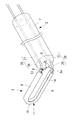
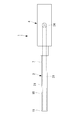
本実施形態に係る結紮デバイス1は、図1に示されるように、細長い筒状のシャフト2と、該シャフト2の先端に固定された糸拡張部3と、シャフト2の基端側に設けられた操作部4と、シャフト2を長手方向に貫通して形成された貫通孔5を貫通して配置され、操作部4によって牽引される結紮糸6とを備えている。
本実施形態に係る結紮デバイス1は、図1に示されるように、細長い筒状のシャフト2と、該シャフト2の先端に固定された糸拡張部3と、シャフト2の基端側に設けられた操作部4と、シャフト2を長手方向に貫通して形成された貫通孔5を貫通して配置され、操作部4によって牽引される結紮糸6とを備えている。
シャフト2は、剣状突起下部から心嚢内まで貫通して配置されるシース等を経由して、体外から心嚢内まで挿入され、体外に突出する基端部の操作によって、先端に固定された糸拡張部3の位置および姿勢を調節することができるように、操作力の伝達が行われる力量伝達部7と、該力量伝達部7の先端部に配置され、先端を一方向に湾曲させる湾曲機構(角度変更部)8とを備えている。
糸拡張部3は、図1および図2に示されるように、例えば、樹脂等の弾性材料により2本の略平行な直線部9と該直線部9を連結する円弧状部分である先端部10とから略U字状に形成された保持部11と、該保持部11のU字の開放端をシャフト2に固定に固定するフレーム部12とを備えている。U字状の保持部11とフレーム部12とによって、糸拡張部3は、シャフト2の先端に固定された略長円の環状の形態を有している。
フレーム部12は、図1に示されるように、湾曲機構8によってシャフト2が湾曲させられていない状態では、U字状の保持部11が、外力のかからない自由状態において、2本の直線部9の中心軸とシャフト2の長手軸とが所定の角度をなして交差するように癖づけられている。
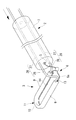
そして、湾曲機構8は、図3に示されるように、U字状の保持部11の2本の直線部9に平行な軸線回りに、糸拡張部3の角度を変化させる方向に、シャフト2を湾曲させるようになっている。
結紮糸6は、一端に結び目6bによって形成されたループ状部分6aが設けられている。ループ状部分6aは、結紮糸6の他端を牽引することによって緊縮可能に構成されている。結紮糸6の結び目6bは、図2に示されるように、貫通孔5の直径よりも大きく設けられている。これにより、結紮糸6を基端側に牽引すると、結び目6bが貫通孔5の先端側の開口を塞いだ状態で固定され、この状態で結紮糸6の牽引を続けることにより、ループ状部分6aの径が小さくなって結紮を行うようになっている。
糸拡張部3の保持部11には、結紮糸6のループ状部分6aの一部を収容する収容孔13が全長にわたって設けられており、該収容孔13には、糸拡張部3の径方向内方に開口するスリット14が設けられている。
スリット14は、収容孔13に収容された結紮糸6が脱落しないように閉じており、結紮糸6の他端が牽引されることによって結紮糸6に張力が付与されて、ループ状部分6aが緊縮させられると、スリット14を介して収容孔13の外部にループ状部分6aが引き出されるようになっている。すなわち、糸拡張部3は、結紮糸6のループ状部分6aを収容孔13に収容することによって広げた状態に保持しており、ループ状部分6aの内側に左心耳Xを容易に挿入することができるようになっている。
そして、糸拡張部3の内側に左心耳Xが挿入されて、糸拡張部3が左心耳Xの根元付近に配置されたときに、結紮糸6の他端に牽引力を作用させることによって、左心耳Xの周囲に配置されているループ状部分6aを緊縮させて、スリット14を介して内側に引き出し、ループ状部分6aによって左心耳Xの根元を直接結紮することができるようになっている。
このように構成された本実施形態に係る結紮デバイス1の作用について以下に説明する。
本実施形態に係る結紮デバイス1を用いて心臓の左心耳Xを結紮するには、予め剣状突起下部から心嚢内まで貫通するように差し込んだシースの内孔(チャネル)を経由して、糸拡張部3側からシャフト2を心嚢内に挿入する。
本実施形態に係る結紮デバイス1を用いて心臓の左心耳Xを結紮するには、予め剣状突起下部から心嚢内まで貫通するように差し込んだシースの内孔(チャネル)を経由して、糸拡張部3側からシャフト2を心嚢内に挿入する。
糸拡張部3は、シース内では、シースの内孔壁面によって弾性変形により真っ直ぐに延ばされ、またはシャフト2側に折りたたまれて、2本の直線部9の間隔も狭められた状態に拘束される。これにより、細いシースの内孔内を心嚢内に向けて挿入していくことができる。
そして、シースの先端開口から突出可能かつ折りたたまれた(収縮させた)状態で収容されている糸拡張部3がシースの先端開口から心嚢内に露出させられると、シースの内孔内壁による拘束から開放された自由状態となるので、2本の直線部9の間隔が広げられ、かつ、フレーム部12の癖付けによって、保持部11がシャフト2の長手軸に対して一方向に傾斜するように弾性変形が復元する。
これにより、保持部11の収容孔13内に保持されている結紮糸6のループ状部分6aは、保持部11と同じ大きさに広げられた状態に保持される。
この状態で、体外においてシャフト2の他端を操作して、糸拡張部3を心尖側から左心耳Xに近接させ、糸拡張部3の保持部11の内側に左心耳Xを挿入していく。
この状態で、体外においてシャフト2の他端を操作して、糸拡張部3を心尖側から左心耳Xに近接させ、糸拡張部3の保持部11の内側に左心耳Xを挿入していく。
このとき、湾曲機構8を作動させることなく、シャフト2を真っ直ぐな形態に保持しておくことにより、シャフト2の先端の糸拡張部3をシャフト2の長手方向に開口するように配置しておくことができる。したがって、シャフト2を長手方向に押すことによって、左心耳Xを糸拡張部3内に容易に挿入することができる。
また、このとき、別途挿入した把持鉗子15によって左心耳Xの先端を引っ張りながら、シャフト2を押して糸拡張部3を押し込んでいくことにより、図2に示されるように、糸拡張部3を左心耳Xの根元付近に配置することができる。
この場合において、左心耳Xは、心臓の表面から突出し、心臓の表面に沿って延びているので、心臓の表面に沿う方向に心尖側から挿入されてきた糸拡張部3は、図2に示されるように、心臓と左心耳Xとの間に配置されている一方の直線部9については、心臓と左心耳Xとの境界近くに配置することができるが、他方の直線部9については、心臓と左心耳Xとの境界から離れた位置にしか配置することができない。
この場合において、左心耳Xは、心臓の表面から突出し、心臓の表面に沿って延びているので、心臓の表面に沿う方向に心尖側から挿入されてきた糸拡張部3は、図2に示されるように、心臓と左心耳Xとの間に配置されている一方の直線部9については、心臓と左心耳Xとの境界近くに配置することができるが、他方の直線部9については、心臓と左心耳Xとの境界から離れた位置にしか配置することができない。
本実施形態に係る結紮デバイス1によれば、図3に示されるように、湾曲機構8を作動させてシャフト2を湾曲させ、糸拡張部3の配置されている面を倒すことにより、両方の直線部9を心臓と左心耳Xとの境界に近づけることができるという利点がある。その結果、図3に示されるように配置された糸拡張部3から開放された結紮糸6のループ状部分6aによって、左心耳Xの根元により近い部分を結紮することができる。
また、本実施形態によれば、略U字状の保持部11が、ほぼ全周にわたってループ状部分6aを収容孔13内に収容しているので、左心耳Xを保持部11内に挿入する操作中にループ状部分6aが左心耳Xに引っかかることがなく、作業を容易にすることができる。
また、一定の間隔をあけて略平行に配置される2つの直線部9によって、糸拡張部3が略長円状または略長方形状に形成されているので、間に挿入される左心耳Xを厚さ方向に挟んで近接する位置に配置することができる。したがって、2つの直線部9の間に挿入した左心耳Xの表面から大きく離れない位置に先端部10のループ状部分を配置することができる。
その結果、牽引されることにより、スリット14を介して収容孔13から引き出されたループ状部分6aは、引き出されるとすぐに近接している左心耳Xに接触してその位置で結紮を行うことができる。
その結果、牽引されることにより、スリット14を介して収容孔13から引き出されたループ状部分6aは、引き出されるとすぐに近接している左心耳Xに接触してその位置で結紮を行うことができる。
なお、本実施形態においては、シャフト2を湾曲させる湾曲機構8により糸拡張部3の角度を変更する角度変更部を構成する例を説明したが、これに代えて、以下のいずれかの角度変更部を採用してもよい。
第1に、図4Aおよび図4Bに示されるように、保持部11を支持するフレーム部26を構成するワイヤ部材を、シャフト2に形成されたルーメン27内に移動可能に挿入しておき、少なくとも一方のフレーム部26を、ルーメン27から押し出された状態で湾曲するように癖づけておくことにより、角度変更部28を構成してもよい。
すなわち、心嚢内において、糸拡張部3内に左心耳Xが挿入されるまで、図4Aに示されるように、シャフト2のルーメン27内にフレーム部26を収容しておく。そして、糸拡張部3内に十分に左心耳Xが挿入された時点で、図4Bに示されるように、一方のフレーム部26をシャフト2のルーメン27の先端開口から押し出す。これにより、湾曲するように癖づけられたフレーム部26を露出させて、糸拡張部3の角度を変更して、保持部11全体が左心耳Xの根元付近に近づくように配置することができる。
第2に、図5に示されるように、糸拡張部3の保持部11を支持するフレーム部31を、シャフト2を長手方向に貫通して設けられたルーメン32内に貫通状態に配置される単一の棒状あるいはワイヤ状の部材によって構成し、該フレーム部31をルーメン32内で長手軸回りに回転可能に支持することにより、角度変更部33を構成してもよい。シャフト2およびフレーム部31は、自由状態において湾曲するように癖づけられていればよい。これにより、シャフト2の基端側においてフレーム部31を捩ることにより、糸拡張部3を回転させることができる。フレーム部31を中空部材により構成し、結紮糸6を貫通させることにしてもよい。
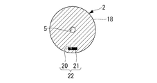
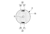
第3に、図6Aに示されるように、樹脂等の弾性材料により形成された弾性変形部18と、比較的硬質の材料により構成された先端部(先端部材)19とをシャフト2の先端に設けるとともに、力量伝達部7および弾性変形部18を長手方向に貫通するルーメン20と、該ルーメン20内に挿入されて先端部19に固定されるワイヤ21とを備える角度変更部22を採用してもよい。
この場合、図7および図9に示されるように、ルーメン20は、シャフト2の径方向位置において、貫通孔5を挟んで先端部19に固定されている2つのフレーム部12の一方よりも径方向外側に配置されている。これにより、貫通孔5、2つのフレーム部12およびルーメン20の位置が同一直線上に配列され、保持部11の回転方向とワイヤ21による湾曲方向とが合致し、弾性変形部18の湾曲を最短で保持部11を回転させることができる。
すなわち、心嚢内において、糸拡張部3内に左心耳Xが挿入されるまで、図6Aおよび図10Aに示されるように、操作部4に設けられワイヤ21の基端が固定されているスライダ23を先端側に配置して弾性変形部18を真っ直ぐな形態で保持しておく。次いで、糸拡張部3内に十分に左心耳Xが挿入された時点で、図6Bおよび図10Bに示されるように、スライダ23を基端側にスライドさせてワイヤ21を牽引し、弾性変形部18を弾性変形させる。これにより、糸拡張部3の角度を変更して、保持部11全体が左心耳Xの根元付近に近づくように配置することができる。
第4に、図11A、図11Bおよび図12に示されるように、シャフト2の径方向位置において貫通孔5を挟んで設けられ、力量伝達部7および弾性変形部18を長手方向に貫通する2つのルーメン20と、各該ルーメン20内に挿入されて先端部19に固定される2本のワイヤ21とを備える角度変更部22を採用してもよい。
この場合、糸拡張部3の角度は、図14Aに示されるように、操作部4に設けられ各ワイヤ21の基端が固定されている回転ハンドル24により変更されるようになっている。回転ハンドル24を一方の方向に回転させると、図14Bに示されるように、回転ハンドル24に固定されている一方のワイヤ21が基端側に牽引され、他方のワイヤ21が先端側に押し出されて弾性変形部18を弾性変形させるようになっている。
すなわち、回転ハンドル24の回転方向および回転量に基づいて糸拡張部3の角度を変更し、保持部11全体が左心耳Xの根元付近に近づくように配置することができる。
また、2本のワイヤ21によって糸拡張部3の角度を変更するため、1本のワイヤ21で糸拡張部3の角度を変更する場合と比較して、1本あたりにかかる張力が半減し、安定して弾性変形部18を弾性変形させることができる。
また、2本のワイヤ21によって糸拡張部3の角度を変更するため、1本のワイヤ21で糸拡張部3の角度を変更する場合と比較して、1本あたりにかかる張力が半減し、安定して弾性変形部18を弾性変形させることができる。
また、ワイヤ21として、図7および図12に示されるように、円形状の断面を有するワイヤを用いた例を説明したが、これに代えて、図8および図13に示されるように、長方形の断面や他の断面形状であってもよい。
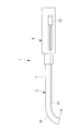
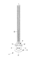
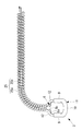
第5に、図15Aおよび図15Bに示されるように、シャフト2に代えて、コイルシース25を用いてもよい。また、シャフト2の先端側の一部分にコイルシース25を用いるようにしてもよい。また、コイルシース25は、弾発力の異なる2種類のコイルを長手軸方向に繋ぎ合わせ、先端側のコイルの弾発力が基端側のコイルの弾発力よりも小さくなるように構成してもよい。
この場合、心嚢内において、糸拡張部3内に左心耳Xが挿入されるまで、図15Aに示されるように、コイルシース25を真っ直ぐな形態で保持しておく。次いで、糸拡張部3内に十分に左心耳Xが挿入された時点で、結紮糸6を基端側に牽引すると、結び目6bがコイルシース25の貫通孔の先端側の開口を塞いだ状態で固定される。この状態で結紮糸6の牽引を続け、結紮糸6の張力がコイルシース25の弾発力を上回ると、図15Bに示されるように、コイルシース25が湾曲して糸拡張部3の角度を変更するようになっている。これにより、保持部11全体が左心耳Xの根元付近に近づくように配置することができる。
また、湾曲用のワイヤ21を用いずに糸拡張部3の角度を変更するため、結紮デバイス1の体内に挿入する部分を細くすることができ、糸拡張部3の角度変更をより容易に実行することができる。
また、湾曲用のワイヤ21を用いずに糸拡張部3の角度を変更するため、結紮デバイス1の体内に挿入する部分を細くすることができ、糸拡張部3の角度変更をより容易に実行することができる。
1 結紮デバイス
2 シャフト
3 糸拡張部
4 操作部
6 結紮糸
6a ループ状部分
8 湾曲機構(角度変更部)
12,26,31 フレーム部(基端部)
18 弾性変形部
19 先端部(先端部材)
20 ルーメン
21 ワイヤ
22,28,33 角度変更部
25 コイルシース
2 シャフト
3 糸拡張部
4 操作部
6 結紮糸
6a ループ状部分
8 湾曲機構(角度変更部)
12,26,31 フレーム部(基端部)
18 弾性変形部
19 先端部(先端部材)
20 ルーメン
21 ワイヤ
22,28,33 角度変更部
25 コイルシース
Claims (8)
- 緊縮可能なループ状部分を備える結紮糸と、
細長いシャフトと、
該シャフトの先端部に設けられ、前記結紮糸の前記ループ状部分を前記シャフトの長手軸に交差する面に沿って広げた状態で、解放可能に保持する糸拡張部と、
該糸拡張部の、前記シャフトに接続する基端部から先端部に向かって延びる軸線回りの角度を変化させる角度変更部とを備える結紮デバイス。 - 前記角度変更部が、前記シャフトの先端部において該シャフトを湾曲させる湾曲機構である請求項1に記載の結紮デバイス。
- 前記シャフトの基端側において、前記角度変更部による前記糸拡張部の角度を調節する操作部を備える請求項1または請求項2に記載の結紮デバイス。
- 前記シャフトがコイルシースである請求項1に記載の結紮デバイス。
- 前記角度変更部が、前記シャフトの先端部に設けられた弾性変形部を貫通するルーメンに挿入され、前記弾性変形部の先端側に設けられた先端部材に一端が固定され、前記操作部に他端が固定されたワイヤを備える請求項3に記載の結紮デバイス。
- 前記ワイヤが、前記シャフトの長手軸を挟んで径方向に2本設けられている請求項5に記載の結紮デバイス。
- 前記コイルシースは、先端側のコイルの弾発力が基端側のコイルの弾発力よりも小さい2種類の異なるコイルからなる請求項4に記載の結紮デバイス。
- 前記糸拡張部が、該糸拡張部を先端開口から突出可能かつ収縮させた状態で収容するチャネルの先端開口から露出させられた位置で、前記結紮糸の前記ループ状部分を前記シャフトの長手軸に交差する面に沿って広げるように拡張する請求項1の記載の結紮デバイス。
Priority Applications (2)
| Application Number | Priority Date | Filing Date | Title |
|---|---|---|---|
| PCT/JP2016/062668 WO2017183161A1 (ja) | 2016-04-21 | 2016-04-21 | 結紮デバイス |
| JP2018512725A JPWO2017183161A1 (ja) | 2016-04-21 | 2016-04-21 | 結紮デバイス |
Applications Claiming Priority (1)
| Application Number | Priority Date | Filing Date | Title |
|---|---|---|---|
| PCT/JP2016/062668 WO2017183161A1 (ja) | 2016-04-21 | 2016-04-21 | 結紮デバイス |
Publications (1)
| Publication Number | Publication Date |
|---|---|
| WO2017183161A1 true WO2017183161A1 (ja) | 2017-10-26 |
Family
ID=60115779
Family Applications (1)
| Application Number | Title | Priority Date | Filing Date |
|---|---|---|---|
| PCT/JP2016/062668 Ceased WO2017183161A1 (ja) | 2016-04-21 | 2016-04-21 | 結紮デバイス |
Country Status (2)
| Country | Link |
|---|---|
| JP (1) | JPWO2017183161A1 (ja) |
| WO (1) | WO2017183161A1 (ja) |
Cited By (2)
| Publication number | Priority date | Publication date | Assignee | Title |
|---|---|---|---|---|
| WO2019202764A1 (ja) * | 2018-04-20 | 2019-10-24 | オリンパス株式会社 | 処置具 |
| CN113057709A (zh) * | 2021-04-30 | 2021-07-02 | 胡梦思 | 一种心耳夹闭系统 |
Citations (2)
| Publication number | Priority date | Publication date | Assignee | Title |
|---|---|---|---|---|
| US20150182225A1 (en) * | 2013-12-30 | 2015-07-02 | Atricure, Inc. | Systems and methods for left atrial appendage closure |
| JP2015195837A (ja) * | 2014-03-31 | 2015-11-09 | オリンパス株式会社 | 心耳結紮用処置具および心耳結紮システム |
-
2016
- 2016-04-21 JP JP2018512725A patent/JPWO2017183161A1/ja active Pending
- 2016-04-21 WO PCT/JP2016/062668 patent/WO2017183161A1/ja not_active Ceased
Patent Citations (2)
| Publication number | Priority date | Publication date | Assignee | Title |
|---|---|---|---|---|
| US20150182225A1 (en) * | 2013-12-30 | 2015-07-02 | Atricure, Inc. | Systems and methods for left atrial appendage closure |
| JP2015195837A (ja) * | 2014-03-31 | 2015-11-09 | オリンパス株式会社 | 心耳結紮用処置具および心耳結紮システム |
Cited By (2)
| Publication number | Priority date | Publication date | Assignee | Title |
|---|---|---|---|---|
| WO2019202764A1 (ja) * | 2018-04-20 | 2019-10-24 | オリンパス株式会社 | 処置具 |
| CN113057709A (zh) * | 2021-04-30 | 2021-07-02 | 胡梦思 | 一种心耳夹闭系统 |
Also Published As
| Publication number | Publication date |
|---|---|
| JPWO2017183161A1 (ja) | 2019-02-28 |
Similar Documents
| Publication | Publication Date | Title |
|---|---|---|
| JP6794548B2 (ja) | 楕円形状を部分的に有する、再搭載可能な止血クリップ装置の為のカプセル | |
| US9987017B2 (en) | Tissue aperture securing and sealing apparatuses and related methods of use | |
| CN111163711B (zh) | 用于可重新装载的止血夹装置的自对齐拉线 | |
| JP7009613B2 (ja) | 再装荷可能な回動式クリップ | |
| JP6084347B1 (ja) | 内視鏡用処置具 | |
| JP6332998B2 (ja) | 心耳結紮用処置具 | |
| WO2017090473A1 (ja) | 接続構造および接続方法 | |
| CN107028655A (zh) | 内窥镜用圈套器 | |
| JP5784856B2 (ja) | 縫合器 | |
| US20180078261A1 (en) | Applicator For Reloadable Hemostatic Clip | |
| US20190223875A1 (en) | Dual support jaw design | |
| JP6632930B2 (ja) | 結紮装置用クリップユニット及び該クリップユニットの係合方法 | |
| EP3905970B1 (en) | Hemostasis clip short system | |
| WO2017183161A1 (ja) | 結紮デバイス | |
| JP4046981B2 (ja) | 内視鏡用クリップ装置 | |
| JP2019097907A (ja) | 内視鏡用スネア | |
| JP7182716B2 (ja) | 内視鏡用処置具 | |
| JP2017012532A (ja) | 結紮装置用クリップユニット及びクリップユニット用カートリッジ | |
| JP3917466B2 (ja) | 内視鏡用クリップ装置 | |
| US12256956B2 (en) | Methods for coupling device components and related devices having such components | |
| US20260102166A1 (en) | Clip unit | |
| JP2005118102A (ja) | 内視鏡用スネア | |
| WO2019008704A1 (ja) | 内視鏡用処置具 | |
| CN115644966A (zh) | 内窥镜缝合器 | |
| JPWO2017183174A1 (ja) | 結紮デバイス |
Legal Events
| Date | Code | Title | Description |
|---|---|---|---|
| ENP | Entry into the national phase |
Ref document number: 2018512725 Country of ref document: JP Kind code of ref document: A |
|
| NENP | Non-entry into the national phase |
Ref country code: DE |
|
| 121 | Ep: the epo has been informed by wipo that ep was designated in this application |
Ref document number: 16899433 Country of ref document: EP Kind code of ref document: A1 |
|
| 122 | Ep: pct application non-entry in european phase |
Ref document number: 16899433 Country of ref document: EP Kind code of ref document: A1 |