WO2017179709A1 - 情報処理装置及び表示システム - Google Patents
情報処理装置及び表示システム Download PDFInfo
- Publication number
- WO2017179709A1 WO2017179709A1 PCT/JP2017/015323 JP2017015323W WO2017179709A1 WO 2017179709 A1 WO2017179709 A1 WO 2017179709A1 JP 2017015323 W JP2017015323 W JP 2017015323W WO 2017179709 A1 WO2017179709 A1 WO 2017179709A1
- Authority
- WO
- WIPO (PCT)
- Prior art keywords
- viewpoint
- correction
- information processing
- touch panel
- input position
- Prior art date
- Legal status (The legal status is an assumption and is not a legal conclusion. Google has not performed a legal analysis and makes no representation as to the accuracy of the status listed.)
- Ceased
Links
Images



Classifications
-
- G—PHYSICS
- G06—COMPUTING OR CALCULATING; COUNTING
- G06F—ELECTRIC DIGITAL DATA PROCESSING
- G06F3/00—Input arrangements for transferring data to be processed into a form capable of being handled by the computer; Output arrangements for transferring data from processing unit to output unit, e.g. interface arrangements
- G06F3/01—Input arrangements or combined input and output arrangements for interaction between user and computer
- G06F3/011—Arrangements for interaction with the human body, e.g. for user immersion in virtual reality
- G06F3/013—Eye tracking input arrangements
-
- G—PHYSICS
- G06—COMPUTING OR CALCULATING; COUNTING
- G06F—ELECTRIC DIGITAL DATA PROCESSING
- G06F3/00—Input arrangements for transferring data to be processed into a form capable of being handled by the computer; Output arrangements for transferring data from processing unit to output unit, e.g. interface arrangements
- G06F3/01—Input arrangements or combined input and output arrangements for interaction between user and computer
- G06F3/03—Arrangements for converting the position or the displacement of a member into a coded form
- G06F3/041—Digitisers, e.g. for touch screens or touch pads, characterised by the transducing means
-
- G—PHYSICS
- G06—COMPUTING OR CALCULATING; COUNTING
- G06F—ELECTRIC DIGITAL DATA PROCESSING
- G06F3/00—Input arrangements for transferring data to be processed into a form capable of being handled by the computer; Output arrangements for transferring data from processing unit to output unit, e.g. interface arrangements
- G06F3/01—Input arrangements or combined input and output arrangements for interaction between user and computer
- G06F3/03—Arrangements for converting the position or the displacement of a member into a coded form
- G06F3/041—Digitisers, e.g. for touch screens or touch pads, characterised by the transducing means
- G06F3/0416—Control or interface arrangements specially adapted for digitisers
-
- G—PHYSICS
- G06—COMPUTING OR CALCULATING; COUNTING
- G06F—ELECTRIC DIGITAL DATA PROCESSING
- G06F3/00—Input arrangements for transferring data to be processed into a form capable of being handled by the computer; Output arrangements for transferring data from processing unit to output unit, e.g. interface arrangements
- G06F3/01—Input arrangements or combined input and output arrangements for interaction between user and computer
- G06F3/03—Arrangements for converting the position or the displacement of a member into a coded form
- G06F3/041—Digitisers, e.g. for touch screens or touch pads, characterised by the transducing means
- G06F3/0416—Control or interface arrangements specially adapted for digitisers
- G06F3/0418—Control or interface arrangements specially adapted for digitisers for error correction or compensation, e.g. based on parallax, calibration or alignment
Definitions
- This disclosure relates to an information processing apparatus that performs predetermined control based on an input to a touch panel.
- the touch panel has a translucent sensor for detecting the position touched by the operator on the surface of the display.
- the display surface and the position touched by the operator are slightly deviated in the normal direction of the display. For this reason, when the operator is positioned obliquely with respect to the display, there is a tendency that the display display and the touched position are easily shifted, and the intended operation cannot be performed.
- Patent Document 1 a technique for detecting the position of the operator and correcting the input position according to the position is proposed.
- One aspect of the present disclosure is an information processing apparatus, which includes a position acquisition unit, a viewpoint acquisition unit, a correction unit, and a determination unit.
- the position acquisition unit is configured to acquire an input position to a touch panel arranged on a display screen of a display device that displays an image.
- the viewpoint acquisition unit is configured to acquire the viewpoint of an operator who performs an input operation on the touch panel.
- the correction unit is configured to correct the input position with respect to the touch panel.
- the determination unit is configured to determine whether the input position acquired by the position acquisition unit and the viewpoint acquired by the viewpoint acquisition unit satisfy at least one predetermined correction condition. Has been.
- the correction unit is configured to correct the input position based on at least the viewpoint when the determination unit determines that the at least one correction condition is satisfied. On the other hand, when the determination unit does not determine that the at least one correction condition is satisfied by the determination unit, the correction unit compares the determination unit with the determination that the at least one correction condition is satisfied. The input position is corrected so as to reduce the influence of the viewpoint.
- the input position is corrected based on the viewpoint. Therefore, it is possible to suppress an input that the operator does not desire.
- the influence of the correction by the viewpoint is reduced, so that it is possible to suppress the correction by the viewpoint when the correction by the viewpoint is not appropriate, and an input not desired by the operator can be performed. It can suppress going.
- Another aspect of the present disclosure detects a display device configured to display an image, a touch panel disposed on a display screen of the display device, and a viewpoint of an operator who performs an input operation on the touch panel.
- the display system includes: a viewpoint detection device configured as described above; and an information processing device configured to execute predetermined control in response to an input operation to the touch panel.
- the information processing apparatus includes a position acquisition unit, a viewpoint acquisition unit, a correction unit, and a determination unit.
- the position acquisition unit is configured to acquire an input position to the touch panel based on a signal output from the touch panel.
- the viewpoint acquisition unit is configured to acquire the viewpoint based on a signal output from the viewpoint detection device.
- the correction unit is configured to correct the input position with respect to the touch panel.
- the determination unit is configured to determine whether the input position acquired by the position acquisition unit and the viewpoint acquired by the viewpoint acquisition unit satisfy at least one predetermined correction condition. Has been.
- the correction unit is configured to correct the input position based on at least the viewpoint when the determination unit determines that the at least one correction condition is satisfied. On the other hand, when the determination unit does not determine that the at least one correction condition is satisfied by the determination unit, the correction unit compares the determination unit with the determination that the at least one correction condition is satisfied. The input position is corrected so as to reduce the influence of the viewpoint.
- the information processing apparatus is the same as the information processing apparatus in the one aspect of the present disclosure described above, an input that the operator does not desire is input as in the information processing apparatus. It can suppress going.
- a display system 1 shown in FIG. 1 is a system used by being mounted on a vehicle such as an automobile.
- the display system 1 includes a display 11, a touch panel 12, a line-of-sight detection device 13, a determination device 14, a vehicle battery 15, and an electronic control unit (hereinafter, ECU) 16.
- the ECU 16 corresponds to an information processing device.
- the display 11 is a display device having a display screen such as a liquid crystal or an organic EL capable of displaying an image, and displays an image according to a signal input from the ECU 16.
- the touch panel 12 is an input device that has a sensor that transmits light arranged on the display screen of the display 11 and receives an input operation on the sensor. In this embodiment, a capacitive touch panel is employed. The touch panel 12 accepts the touch operation of the operator 3 as an input, and outputs an input signal to the ECU 16.
- the line-of-sight detection device 13 has a camera 18a for photographing a driver and a camera 18b for photographing a passenger.
- the line-of-sight detection device 13 analyzes images acquired from these cameras and detects the viewpoint of the operator 3 who performs an input operation on the touch panel 12, the position of the eyes in the vehicle, and the line-of-sight direction.
- the line-of-sight detection device 13 calculates these information at predetermined time intervals and outputs them to the ECU 16.
- a well-known technique can be used as a method of detecting the viewpoint, the eye position, and the line-of-sight direction by image analysis.
- the passenger particularly refers to the passenger in the passenger seat.
- This line-of-sight detection device 13 corresponds to a viewpoint detection device.
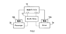
- the discrimination device 14 has capacitively coupled electrodes 14a and 14b installed in the driver seat and the passenger seat, respectively.
- the driver side circuit including the touch panel 12, the driver 3a, the capacitively coupled electrode 14a, and the determination device 14 is turned on. Thereby, it can be determined that the operator of the touch panel 12 is the driver 3a.
- the circuit on the passenger 3b side is turned on, it can be determined that the operator of the touch panel 12 is the passenger 3b.
- the determination result is output to the ECU 16.
- the vehicle battery 15 supplies electric power to the ECU 16.
- the ECU 16 includes a microcomputer having a CPU 21 and a semiconductor memory (hereinafter, memory 22) such as a RAM, a ROM, and a flash memory.
- memory 22 a semiconductor memory
- Various functions of the ECU 16 are realized by the CPU 21 executing a program stored in a non-transitional physical recording medium.
- the memory 22 corresponds to a non-transitional tangible recording medium that stores a program. Further, by executing this program, a method corresponding to the program is executed.
- the ECU 16 may include a single microcomputer or a plurality of microcomputers.
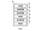
- the ECU 16 includes a specification unit 31, a position acquisition unit 32, a viewpoint acquisition unit 33, a determination unit 34, and condition setting as a configuration of functions realized by the CPU 21 executing a program.
- a unit 35 and a correction unit 36 are provided.
- the method of realizing these elements in the ECU 16 is not limited to software, and some or all of the elements may be realized using hardware combining a logic circuit, an analog circuit, and the like.
- the identifying unit 31 identifies which seat in the vehicle the operator 3 who operates the touch panel 12 is.
- the target seats in this embodiment are a driver seat and a passenger seat.
- the touch panel 12 when the touch panel 12 is arrange
- the position acquisition unit 32 acquires an input position that is a position touched by the operator 3 on the touch panel 12. When the operator 3 touches the touch panel 12, an input signal is output from the touch panel 12. Based on the signal, the position acquisition unit 32 specifies the position on the touch panel 12 that the operator 3 has touched.
- the viewpoint acquisition unit 33 acquires the viewpoint of the operator 3, the eye point that is the position of the eye of the operator 3, and the line of sight based on the signal output from the line-of-sight detection device 13.
- the viewpoint of the operator 3 here is a point on the display screen of the display 11 and is specified by three-dimensional coordinates.
- the eye point is specified by coordinates on a three-dimensional space in the vehicle.
- the line of sight is a straight line connecting the viewpoint and the eye point.
- the determination unit 34 determines whether the input position of the touch panel 12 acquired by the position acquisition unit 32 and the viewpoint of the operator 3 acquired by the viewpoint acquisition unit 33 satisfy a predetermined correction condition.
- the correction condition in the present embodiment is that the distance between the input position and the viewpoint is equal to or less than a predetermined threshold value.
- the condition setting unit 35 sets the correction conditions described above. That is, the condition setting unit 35 changes the above-described threshold according to the situation.
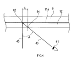
- a method for setting the correction condition will be described with reference to FIG.
- the threshold value described above is the distance L between the intersection position 44 that is a position that intersects the line of sight 43 on the surface of the touch panel 12 and the viewpoint 42.
- a display screen 11 a exists at a boundary portion of the display 11 with the touch panel 12.
- the viewpoint acquisition unit 33 acquires a line of sight 43 connecting the eye point 41 and the viewpoint 42.
- the memory 22 stores the distance from the surface on the touch panel 12 side of the display 11, that is, the display screen 11 a to the surface of the touch panel 12. From these, the coordinates of the intersection position 44 can be calculated.
- the condition setting unit 35 obtains the line of sight 43, calculates the value of the distance L at that time, and sets it as a threshold value for the correction condition.
- the correction unit 36 corrects the input position with respect to the touch panel 12.
- the content of the correction varies depending on whether or not the determination unit 34 determines that the correction condition is satisfied.
- the correction condition is satisfied, at least correction based on the detected viewpoint 42 is performed.
- the correction condition is not satisfied, correction is performed with a lower degree of influence of the viewpoint 42 than when the correction condition is satisfied.
- the correction that reduces the degree of influence of the viewpoint 42 includes correction that does not consider the viewpoint 42 at the time of performing correction, and further includes that the correction amount is 0, that is, no correction is performed. .
- the above-described degree of influence of the viewpoint can also be said to be a ratio in which the viewpoint parameter is involved in the corrected input position.
- the input position after the correction is performed is also referred to as a correction position regardless of whether or not there is an influence of the viewpoint.
- the correction position when the correction condition is satisfied is closer to the viewpoint 42 than the correction position when the correction condition is not satisfied or the input position when correction is not performed.
- the determination unit 34 determines that the correction condition is satisfied, the input position is corrected to the position of the viewpoint 42. That is, the position of the viewpoint 42 becomes the correction position as it is.
- FIG. 5 is a view of the display 11 and the touch panel 12 as viewed from the front.
- FIG. 5 shows a sufficiently large distance between the viewpoint 42 and the intersection position 44 for the purpose of facilitating understanding.
- the correction range 47 is a circle whose center is the viewpoint 42 and whose radius is set to the distance L. If the input position 51 by the finger 49 of the operator 3 is an area inside the correction range 47, the distance between the viewpoint 42 and the input position 51 is equal to or less than the distance L, which satisfies the correction condition. On the other hand, if the input position 51 is an area outside the correction range 47, the correction condition is not satisfied. In this way, the correction condition can also be said to be that the input position 51 is within a predetermined range centered on the viewpoint 42.
- the correction condition is a condition in which correction is performed so that the correction position becomes the position of the viewpoint 42 when the intersection position 44 is touched.
- the threshold value in the correction condition may be set larger than the distance L so that the input position 51 may deviate from the intersection position 44 in the direction opposite to the viewpoint 42.
- the ECU 16 is configured to be able to execute various controls such as screen display, navigation, music, air conditioning, and the like, such as control of the in-vehicle environment and the running state, in accordance with an input operation to the touch panel 12.
- the CPU 21 performs pre-touch detection.
- the touch panel 12 can detect the approach of the finger from the change in capacitance before the finger of the operator 3 contacts the touch panel 12. Here, it is detected that the finger is approaching.
- the CPU 21 acquires information for determining whether the operator 3 is a driver or a passenger from the determination device 14. In S3, the CPU 21 determines whether or not the operator 3 is a passenger. If the operator 3 is a passenger, the process proceeds to S4. On the other hand, if the operator 3 is not a passenger, that is, if the operator 3 is a driver, the process proceeds to S5.
- the CPU 21 enables the passenger seat camera 18b.
- the CPU 21 validates the driver seat camera 18a.
- the CPU 21 acquires the input position 51 of the operator 3 to the touch panel 12.
- the CPU 21 acquires information such as the line of sight 43, the viewpoint 42, and the eye point 41 of the operator 3.
- the CPU 21 calculates a distance L that is a threshold value of the correction condition based on the input position 51 acquired in S6 and the viewpoint 42 acquired in S7.
- the CPU 21 determines whether or not the input position 51 satisfies the correction condition. If the input position 51 satisfies the correction condition, the process proceeds to S10. On the other hand, if the input position 51 does not satisfy the correction condition, the process proceeds to S11.
- the CPU 21 corrects the input position 51 to the position of the viewpoint 42. Thereafter, this process is terminated.
- the process by the ECU 16 is executed assuming that the input operation is performed at the position of the viewpoint 42.
- the CPU 21 corrects the input position 51 without being based on the position of the viewpoint 42.
- an expected input position 52 when a straight line connecting the eye point 41 and the input position 51 is extended to the display 11 is calculated.
- the predicted input position 52 is set as a correction position. Thereafter, this process is terminated.
- the process by the ECU 16 is executed assuming that the input operation is performed at the position of the expected input position 52.
- the ECU 16 causes the operator 3 to view the viewpoint 42 if the viewpoint 42 and the input position 51 satisfy the correction condition, that is, if they are close to the distance L or less. An input operation is accepted as the correction position. Therefore, when the display 11 is viewed from an oblique direction, a deviation occurs between the actual input position 51 of the touch panel 12 and the desired input position, and as a result, the input as desired by the operator cannot be performed. Can be suppressed.
- the viewpoint 42 is not close to the input position 51, the viewpoint 42 is not corrected as the input position 51. Therefore, when the operator is looking at a position completely different from the input position 51, it is possible to suppress an input operation that is not assumed by the operator from being accepted.
- the condition setting unit 35 sets a larger threshold value for the correction condition as the angle A formed between the normal 45 and the line of sight 43 of the display screen 11a of the display 11 increases. Therefore, it is possible to set an appropriate condition according to the eye point 41 of the operator 3.
- the shapes of the display 11 and the touch panel 12 are not particularly limited, but either one or both surfaces of the display 11 and the touch panel 11 may be formed in a curved surface shape.
- a curved touch panel may be arranged on a flat display. In that case, a light-transmitting plate-like member is placed between the display and the touch panel, where one surface is flat along the display and the other surface is curved and the touch panel is placed. May be.
- the viewpoint 42 is set as the correction position on the condition that the distance between the viewpoint 42 and the input position 51 is closer than a predetermined threshold value.
- the present invention is not limited to the contents of the above embodiment.
- the correction condition may be that the input position 51 and the viewpoint 42 are located within a predetermined range based on the position based on the viewpoint 42 or the intersection position 44.
- a correction range 47 a that is a circle centered on the center point 45 of the viewpoint 42 and the intersection position 44, the correction condition is satisfied. You may judge.
- the correction range may be set so as to have a width including the intersection position 44 and the viewpoint 42. With such a correction range, it is possible to correct an erroneous operation that occurs when the operator 3 wants to perform an input operation at the position of the viewpoint 42.
- the correction is performed. It may be determined that the condition is satisfied.
- the straight line 47 b is a straight line that passes through the viewpoint 42.
- the straight line 47 c is a straight line that passes through the intersection position 44.
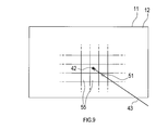
- the touch panel 12 is divided into a plurality of blocks 55 such as rectangles, and a plurality of blocks set in advance for one block 55 where the input position 51 or the viewpoint 42 is located,
- the correction range described above may be used.
- only one block 55 may be the correction range, or one block 55 and a plurality of blocks 55 around it may be the correction range.
- the size of the plurality of blocks 55 may change based on the line-of-sight angle or the like.
- the determination of whether or not to correct the input position is based on whether or not a plurality of correction conditions including other correction conditions are satisfied at the same time as well as one correction condition regarding the input position 51 and the viewpoint 42. You may go.
- the ECU 16 may be configured not to perform correction based on the viewpoint 42 as long as the traveling speed is equal to or higher than a certain value.
- the ECU 16 may be configured to perform correction based on the viewpoint 42 only when the display 11 is being watched for a certain period of time or longer.
- the detected position of the viewpoint 42 may be the position of the viewpoint 42 at the timing when the input operation is performed, or the position of the viewpoint 42 before the input operation, after the input operation, or during a certain period before and after the input operation. It may be a position obtained based on the history. As an example of the latter, it is conceivable to take an arithmetic average of viewpoints for 0.5 seconds immediately before the input operation. However, weighting may be performed or clear noise may be removed.
- the CPU 21 performs the correction with the viewpoint 42 as the input position 51 in S10 of FIG. 6, but the CPU 21 performs a correction process based on the viewpoint 42 different from the above embodiment. You may go.
- the CPU 21 may perform correction using the center position of the input position 51 and the viewpoint 42 as the correction position.
- the CPU 21 selects the button on the side where the viewpoint 42 is located. You may decide that
- the CPU 21 performs the correction not based on the viewpoint 42 in S11 of FIG.
- the CPU 21 may perform another correction process using the viewpoint 42 as a correction that reduces the degree of influence of the viewpoint as compared with the case of S10.
- the CPU 21 may correct the input position 51 and the center position of the viewpoint 42 as the input position 51 in S12, while the viewpoint 42 is set as the correction position in S10. Further, the CPU 21 does not have to perform the correction process in S11.
- the threshold value serving as the correction condition increases as the angle A between the normal line 45 and the line of sight 43 of the display screen 11a of the display 11 increases.
- the threshold value is constant. That is, the threshold value may not change.
- the display system 1 including the ECU 16 as a constituent element, a program for causing a computer to function as the ECU 16, a non-transitory actual recording medium such as a semiconductor memory storing the program, and an input method
- the present disclosure can also be realized in various forms.
Landscapes
- Engineering & Computer Science (AREA)
- General Engineering & Computer Science (AREA)
- Theoretical Computer Science (AREA)
- Human Computer Interaction (AREA)
- Physics & Mathematics (AREA)
- General Physics & Mathematics (AREA)
- User Interface Of Digital Computer (AREA)
- Fittings On The Vehicle Exterior For Carrying Loads, And Devices For Holding Or Mounting Articles (AREA)
Abstract
情報処理装置(16)は、位置取得部と、視点取得部と、補正部と、判定部と、を備える。位置取得部は、タッチパネル(12)への入力位置を取得する。視点取得部は、操作者(3)の視点を取得する。判定部は、上記入力位置と上記視点とが、少なくとも1つの補正条件を満たしているか否かを判定する。補正部は、少なくとも1つの補正条件を満たしていると判定された場合には、少なくとも上記視点に基づいて上記入力位置の補正を行う。また補正部は、少なくとも1つの補正条件を満たしていると判定されていない場合には、補正条件を満たしていると判定された場合よりも上記視点の影響の度合を低くした上記入力位置の補正を行う。
Description
本国際出願は、2016年4月15日に日本国特許庁に出願された日本国特許出願第2016-082232号に基づく優先権を主張するものであり、日本国特許出願第2016-082232号の全内容を本国際出願に参照により援用する。
本開示は、タッチパネルへの入力に基づいて所定の制御を行う情報処理装置に関する。
タッチパネルは、操作者のタッチした位置を検出する透光性のセンサをディスプレイの表面に備えている。ディスプレイ表面と操作者がタッチする位置とは、ディスプレイの法線方向に僅かに乖離している。そのため、操作者がディスプレイに対して斜めに位置する場合には、ディスプレイの表示とタッチする位置とにずれが生じやすく、意図した操作を行えない場合があった。
下記特許文献1では、操作者の位置を検出して、位置に応じた入力位置の補正を行う技術が提案されている。
しかしながら、発明者の詳細な検討の結果、操作者の位置を基準として入力位置を補正するだけでは、入力位置の適切な補正ができず、タッチパネルの誤操作が生じてしまう場合があるという課題が見出された。
本開示の1つの局面は、タッチパネルの誤操作を低減する技術を提供できることが望ましい。
本開示の1つの局面は、情報処理装置であって、位置取得部と、視点取得部と、補正部と、判定部と、を備える。位置取得部は、画像を表示する表示装置の表示画面に配置されるタッチパネルへの入力位置を取得するように構成されている。視点取得部は、上記タッチパネルに対する入力操作を行う操作者の視点を取得するように構成されている。補正部は、上記タッチパネルに対する入力位置の補正を行うように構成されている。判定部は、上記位置取得部により取得された上記入力位置と、上記視点取得部により取得された上記視点と、が、所定の少なくとも1つの補正条件を満たしているか否かを判定するように構成されている。
本開示の1つの局面は、情報処理装置であって、位置取得部と、視点取得部と、補正部と、判定部と、を備える。位置取得部は、画像を表示する表示装置の表示画面に配置されるタッチパネルへの入力位置を取得するように構成されている。視点取得部は、上記タッチパネルに対する入力操作を行う操作者の視点を取得するように構成されている。補正部は、上記タッチパネルに対する入力位置の補正を行うように構成されている。判定部は、上記位置取得部により取得された上記入力位置と、上記視点取得部により取得された上記視点と、が、所定の少なくとも1つの補正条件を満たしているか否かを判定するように構成されている。
また上記補正部は、上記判定部により上記少なくとも1つの補正条件を満たしていると判定された場合には、少なくとも上記視点に基づいて上記入力位置の補正を行うように構成されている。一方、上記補正部は、上記判定部により上記少なくとも1つの補正条件を満たしていると判定されていない場合には、上記少なくとも1つの補正条件を満たしていると判定された場合と比較して上記視点の影響の度合を低くした上記入力位置の補正を行うように構成されている。
このような構成によれば、上記少なくとも1つの補正条件を満たしている場合には視点に基づいて入力位置の補正がなされる。よって、操作者の希望しない入力を行ってしまうことを抑制できる。また少なくとも1つの補正条件を満たしていないときには、視点による補正の影響が小さくなるため、視点による補正が適切でない場合に視点による補正を実行してしまうことが抑制でき、操作者の希望しない入力を行ってしまうことを抑制できる。
本開示の別の1つの局面は、画像を表示するように構成された表示装置と、上記表示装置の表示画面に配置されるタッチパネルと、上記タッチパネルに対する入力操作を行う操作者の視点を検出するように構成されている視点検出装置と、上記タッチパネルへの入力操作に応じて、所定の制御を実行可能に構成されている情報処理装置と、を備える表示システムである。
上記情報処理装置は、位置取得部と、視点取得部と、補正部と、判定部と、を備える。
位置取得部は、上記タッチパネルから出力される信号に基づいて、上記タッチパネルへの入力位置を取得するように構成されている。視点取得部は、上記視点検出装置から出力される信号に基づいて、上記視点を取得するように構成されている。補正部は、上記タッチパネルに対する入力位置の補正を行うように構成されている。判定部は、上記位置取得部により取得された上記入力位置と、上記視点取得部により取得された上記視点と、が、所定の少なくとも1つの補正条件を満たしているか否かを判定するように構成されている。
位置取得部は、上記タッチパネルから出力される信号に基づいて、上記タッチパネルへの入力位置を取得するように構成されている。視点取得部は、上記視点検出装置から出力される信号に基づいて、上記視点を取得するように構成されている。補正部は、上記タッチパネルに対する入力位置の補正を行うように構成されている。判定部は、上記位置取得部により取得された上記入力位置と、上記視点取得部により取得された上記視点と、が、所定の少なくとも1つの補正条件を満たしているか否かを判定するように構成されている。
また上記補正部は、上記判定部により上記少なくとも1つの補正条件を満たしていると判定された場合には、少なくとも上記視点に基づいて上記入力位置の補正を行うように構成されている。一方、上記補正部は、上記判定部により上記少なくとも1つの補正条件を満たしていると判定されていない場合には、上記少なくとも1つの補正条件を満たしていると判定された場合と比較して上記視点の影響の度合を低くした上記入力位置の補正を行うように構成されている。
このような構成によれば、上述した本開示の上記1つの局面における情報処理装置と同様の情報処理装置を有していることから、上記情報処理装置と同様に、操作者の希望しない入力を行ってしまうことを抑制できる。
なお、請求の範囲に記載した括弧内の符号は、一つの態様として後述する実施形態に記載の具体的手段との対応関係を示すものであって、本開示の技術的範囲を限定するものではない。
以下、図面を参照しながら、本開示を実施するための形態を説明する。
[1.実施形態]
[1-1.構成]
図1に示される表示システム1は自動車等の車両に搭載されて用いられるシステムである。表示システム1は、ディスプレイ11と、タッチパネル12と、視線検知デバイス13と、判別デバイス14と、車両バッテリー15と、Electronic Control Unit(以下、ECU)16と、を備えている。なおECU16が、情報処理装置に相当する。
[1.実施形態]
[1-1.構成]
図1に示される表示システム1は自動車等の車両に搭載されて用いられるシステムである。表示システム1は、ディスプレイ11と、タッチパネル12と、視線検知デバイス13と、判別デバイス14と、車両バッテリー15と、Electronic Control Unit(以下、ECU)16と、を備えている。なおECU16が、情報処理装置に相当する。
ディスプレイ11は、画像を表示可能な液晶や有機ELなどの表示画面を有する表示装置であって、ECU16から入力される信号に従って画像を表示する。
タッチパネル12は、ディスプレイ11の表示画面に重ねて配置される光を透過するセンサを有し、該センサに対する入力操作を受け付ける入力装置である。本実施形態では、静電容量方式のタッチパネルを採用している。タッチパネル12は、操作者3のタッチ操作を入力として受け付け、入力信号をECU16に出力する。
タッチパネル12は、ディスプレイ11の表示画面に重ねて配置される光を透過するセンサを有し、該センサに対する入力操作を受け付ける入力装置である。本実施形態では、静電容量方式のタッチパネルを採用している。タッチパネル12は、操作者3のタッチ操作を入力として受け付け、入力信号をECU16に出力する。
視線検知デバイス13は、ドライバーを撮影するカメラ18aとパッセンジャーを撮影するカメラ18bとを有している。視線検知デバイス13は、それらのカメラから取得した画像を画像解析し、タッチパネル12に対する入力操作を行う操作者3の視点、車両内における目の位置、及び視線方向を検出する。視線検知デバイス13はこれらの情報を所定の時間間隔で算出し、ECU16に出力する。画像解析により視点、目の位置や視線方向を検出する方法は周知技術を用いることができる。なお、パッセンジャーとは特に助手席の搭乗者を指す。この視線検知デバイス13が、視点検出装置に相当する。
判別デバイス14は、図2に示されるように、運転席及び助手席それぞれに設置された容量結合型電極14a、14bを有している。そして、運転席にドライバー3aが着席した状態でドライバー3aがタッチパネル12を操作すると、タッチパネル12、ドライバー3a、容量結合型電極14a、及び判別デバイス14により構成されるドライバー側の回路がオンとなる。これにより、タッチパネル12の操作者がドライバー3aであると判別できる。同様に、パッセンジャー3b側の回路がオンとなれば、タッチパネル12の操作者がパッセンジャー3bであると判別できる。判別結果は、ECU16に出力される。
説明を図1に戻る。車両バッテリー15は、ECU16に電力を供給する。
ECU16は、CPU21と、RAM、ROM、フラッシュメモリ等の半導体メモリ(以下、メモリ22)と、を有するマイクロコンピュータを備える。ECU16の各種機能は、CPU21が非遷移的実体的記録媒体に格納されたプログラムを実行することにより実現される。この例では、メモリ22が、プログラムを格納した非遷移的実体的記録媒体に該当する。また、このプログラムの実行により、プログラムに対応する方法が実行される。なお、ECU16は、1つのマイクロコンピュータを備えていてもよいし、複数のマイクロコンピュータを備えていてもよい。
ECU16は、CPU21と、RAM、ROM、フラッシュメモリ等の半導体メモリ(以下、メモリ22)と、を有するマイクロコンピュータを備える。ECU16の各種機能は、CPU21が非遷移的実体的記録媒体に格納されたプログラムを実行することにより実現される。この例では、メモリ22が、プログラムを格納した非遷移的実体的記録媒体に該当する。また、このプログラムの実行により、プログラムに対応する方法が実行される。なお、ECU16は、1つのマイクロコンピュータを備えていてもよいし、複数のマイクロコンピュータを備えていてもよい。
ECU16は、CPU21がプログラムを実行することで実現される機能の構成として、図3に示すように、特定部31と、位置取得部32と、視点取得部33と、判定部34と、条件設定部35と、補正部36と、を備える。ECU16におけるこれらの要素を実現する手法はソフトウェアに限るものではなく、その一部又は全部の要素を、論理回路やアナログ回路等を組み合わせたハードウェアを用いて実現してもよい。
特定部31は、タッチパネル12を操作する操作者3が、車両におけるいずれの座席に座る人であるかを特定する。本実施形態で対象とする座席は、運転席と助手席である。なお、タッチパネル12が上記座席以外の搭乗者により操作可能な位置に配置されているときは、運転席及び助手席以外に座る搭乗者を特定するように構成することができる。
位置取得部32は、タッチパネル12に対して操作者3がタッチした位置である入力位置を取得する。操作者3がタッチパネル12にタッチすると、タッチパネル12から入力信号が出力される。位置取得部32は、その信号に基づいて、操作者3が接触したタッチパネル12上の位置を特定する。
視点取得部33は、操作者3の視点、操作者3の目の位置であるアイポイント、及び視線を、視線検知デバイス13から出力される信号に基づき取得する。ここでいう操作者3の視点とは、ディスプレイ11の表示画面上の地点であって、3次元の座標で特定される。アイポイントは、車両内における3次元空間上の座標で特定される。視線は視点とアイポイントを結ぶ直線である。
判定部34は、位置取得部32により取得されたタッチパネル12の入力位置と、視点取得部33により取得された操作者3の視点と、が、所定の補正条件を満たしているか否かを判定する。本実施形態における補正条件とは、入力位置と視点との距離が所定の閾値以下となっていることである。
条件設定部35は、上述した補正条件を設定する。つまり条件設定部35は、上述した閾値を状況に応じて変化させる。
補正条件の設定の方法を、図4を用いて説明する。上述した閾値は、タッチパネル12の表面における視線43と交差する位置である交差位置44と、視点42と、の距離Lである。図4において、ディスプレイ11におけるタッチパネル12との境界の部分に、表示画面11aが存在する。
補正条件の設定の方法を、図4を用いて説明する。上述した閾値は、タッチパネル12の表面における視線43と交差する位置である交差位置44と、視点42と、の距離Lである。図4において、ディスプレイ11におけるタッチパネル12との境界の部分に、表示画面11aが存在する。
視点取得部33は、アイポイント41と視点42とを結ぶ視線43を取得している。またメモリ22には、ディスプレイ11におけるタッチパネル12側の表面、即ち表示画面11aから、タッチパネル12の表面までの距離が記憶されている。これらから、交差位置44の座標を算出することができる。
ここで、交差位置44は、視点42が同一であっても、ディスプレイ11の法線45と視線43との為す角度Aに応じて変化する。即ち、距離Lの値は、角度Aによって変化する。そこで条件設定部35は、視線43を求めることにより、そのときの距離Lの値を算出し、補正条件の閾値として設定する。
補正部36は、タッチパネル12に対する入力位置の補正を行う。その補正の内容は、判定部34により補正条件を満たしていると判定されているか否かにより変化する。補正条件が満たされている場合、少なくとも検出された視点42に基づく補正が行われる。一方、補正条件が満たされていない場合には、補正条件が満たされている場合と比較して視点42の影響の度合を低くした補正が行われる。ここでいう、視点42の影響の度合を低くした補正とは、補正を行うにあたって全く視点42を考慮しない補正を含むと共に、さらに、補正量が0であること、即ち補正を行わない場合も含む。
上述した、視点の影響の度合、とは、補正後の入力位置において視点のパラメータが関与している割合ということもできる。以下の説明においては、補正が行われた後の入力位置を、視点の影響の有無にかかわらず、補正位置とも記載する。
補正条件が満たされている場合の補正位置は、補正条件が満たされていない場合の補正位置、或いは補正しない場合の入力位置と比較して、より視点42に近い位置となる。
本実施形態では、判定部34により補正条件を満たしていると判定された場合には、入力位置を視点42の位置とする補正を行う。つまり視点42の位置がそのまま補正位置となる。
本実施形態では、判定部34により補正条件を満たしていると判定された場合には、入力位置を視点42の位置とする補正を行う。つまり視点42の位置がそのまま補正位置となる。
図5は、ディスプレイ11及びタッチパネル12を正面から見た図である。図5は、理解を容易にする目的で、視点42と交差位置44との間の距離を十分に大きく示している。補正範囲47は、視点42を中心とし、半径が距離Lに設定された円である。操作者3の指49による入力位置51が、補正範囲47の内側の領域であれば、視点42と入力位置51との距離が距離L以下となり、補正条件を満たす。一方、入力位置51が補正範囲47の外側の領域であれば、補正条件を満たさない。このように、補正条件は、視点42を中心とする所定の範囲内に入力位置51があること、とも言い換えることができる。
交差位置44は、操作者3の視点42とアイポイント41とを結ぶ直線上にあるため、操作者3が視点42をタッチしようとしたときには、交差位置44にタッチしてしまいやすくなる。よって、交差位置44をタッチしたときには、視点42をタッチしたものとして処理を行うことで、操作者3の意図する操作を実現しやすくなる。上記補正条件は、交差位置44をタッチしたときに補正位置が視点42の位置となる補正がなされる条件となっている。
なお、補正条件における閾値は、入力位置51が交差位置44から視点42と反対の方向にずれてもよいように、距離Lよりも大きく設定してもよい。
なお、図示しないが、ECU16は、タッチパネル12への入力操作に応じて、画面表示、ナビゲーション、音楽、空調など、車内環境や走行状態の制御といった様々な制御を実行可能に構成されている。
なお、図示しないが、ECU16は、タッチパネル12への入力操作に応じて、画面表示、ナビゲーション、音楽、空調など、車内環境や走行状態の制御といった様々な制御を実行可能に構成されている。
[1-2.処理]
次に、ECU16のCPU21が実行する位置補正処理について、図6のフローチャートを用いて説明する。
次に、ECU16のCPU21が実行する位置補正処理について、図6のフローチャートを用いて説明する。
まずS1では、CPU21は、プレタッチ検出を行う。タッチパネル12は、操作者3の指がタッチパネル12に接触する前に、静電容量の変化から指の接近を検出できる。ここでは、指が接近したことを検出する。
S2では、CPU21は、判別デバイス14から、操作者3がドライバーであるかパッセンジャーであるかを判別するための情報を取得する。
S3では、CPU21は、操作者3がパッセンジャーであるか否かを判定する。操作者3がパッセンジャーであれば、処理がS4に移行する。一方、操作者3がパッセンジャーでなければ、即ち操作者3がドライバーであれば、処理がS5に移行する。
S3では、CPU21は、操作者3がパッセンジャーであるか否かを判定する。操作者3がパッセンジャーであれば、処理がS4に移行する。一方、操作者3がパッセンジャーでなければ、即ち操作者3がドライバーであれば、処理がS5に移行する。
S4では、CPU21は、パッセンジャー席用のカメラ18bを有効化する。またS5では、CPU21は、ドライバー席用のカメラ18aを有効化する。
S6では、CPU21は、タッチパネル12への操作者3の入力位置51を取得する。
S6では、CPU21は、タッチパネル12への操作者3の入力位置51を取得する。
S7では、CPU21は、操作者3の視線43、視点42、アイポイント41などの情報を取得する。
S8では、CPU21は、S6にて取得した入力位置51と、S7にて取得した視点42と、に基づいて、補正条件の閾値である距離Lを算出する。
S8では、CPU21は、S6にて取得した入力位置51と、S7にて取得した視点42と、に基づいて、補正条件の閾値である距離Lを算出する。
S9では、CPU21は、入力位置51が補正条件を満たすか否かを判定する。入力位置51が補正条件を満たしていれば、処理がS10に移行する。一方、入力位置51が補正条件を満たしていなければ、処理がS11に移行する。
S10では、CPU21は、入力位置51を視点42の位置に補正する。その後、本処理を終了する。このS10の処理により、視点42の位置に入力操作がなされたものとして、ECU16による処理が実行される。
S11では、CPU21は、視点42の位置に基づかずに、入力位置51の補正を行う。ここでは、図7に示されるように、アイポイント41と入力位置51とを結ぶ直線をディスプレイ11まで延長した場合の入力予想位置52を算出する。そして、入力予想位置52を補正位置とする。その後、本処理を終了する。このS11の処理により、入力予想位置52の位置に入力操作がなされたものとして、ECU16による処理が実行される。
[1-3.効果]
以上詳述した第1実施形態によれば、以下の効果が得られる。
(1a)本実施形態の表示システム1では、ECU16は、視点42と入力位置51とが補正条件を満たせば、即ち、それらが距離L以下に接近していれば、操作者3の視点42を補正位置として入力操作を受け付ける。よって、ディスプレイ11を斜め方向から見ることによってタッチパネル12の実際の入力位置51と希望する入力位置との間にずれが生じてしまい、その結果、操作者の希望通りの入力ができなくなってしまうことを抑制できる。
以上詳述した第1実施形態によれば、以下の効果が得られる。
(1a)本実施形態の表示システム1では、ECU16は、視点42と入力位置51とが補正条件を満たせば、即ち、それらが距離L以下に接近していれば、操作者3の視点42を補正位置として入力操作を受け付ける。よって、ディスプレイ11を斜め方向から見ることによってタッチパネル12の実際の入力位置51と希望する入力位置との間にずれが生じてしまい、その結果、操作者の希望通りの入力ができなくなってしまうことを抑制できる。
また、視点42が入力位置51と接近していない場合は、視点42を入力位置51として補正しない。よって、操作者が入力位置51とは全く異なる位置を見ているときに、操作者の想定しない入力操作が受け付けられてしまうことを抑制できる。
(1b)条件設定部35は、ディスプレイ11の表示画面11aの法線45と視線43との為す角度Aが大きくなるほど、補正条件の閾値を大きく設定する。よって、操作者3のアイポイント41に応じた適切な条件を設定することができる。
[2.他の実施形態]
以上、本開示を実施するための形態について説明したが、本開示は上述の実施形態に限定されることなく、種々変形して実施することができる。
以上、本開示を実施するための形態について説明したが、本開示は上述の実施形態に限定されることなく、種々変形して実施することができる。
(2a)上記実施形態では、ディスプレイ11とタッチパネル12の形状については特に限定されていないが、ディスプレイ11及びタッチパネル11のいずれか一方又は両方の表面が曲面状に形成されていてもよい。例えば、平面状のディスプレイに曲面状のタッチパネルが配置されてもよい。なお、その場合には、ディスプレイとタッチパネルの間に、一方の面がディスプレイに沿った平面状であり、他方の面が曲面状でタッチパネルが配置される、光を透過する板状の部材を配置してもよい。
(2b)上記実施形態では、視点42と入力位置51との距離が所定の閾値よりも接近していることを条件として、視点42を補正位置とすることを例示したが、上述した補正条件は、上記実施形態の内容に限定されない。
例えば、視点42や交差位置44などに基づく位置を基準とした所定の範囲内に、入力位置51及び視点42が位置することを補正条件としてもよい。具体的な例としては、図8に示されるように、視点42と交差位置44の中心点45を中心とする円である補正範囲47a内に入力操作がなされたときに、補正条件を満たすと判定してもよい。
なお、このように補正範囲を設定する場合には、補正範囲を、交差位置44と、視点42と、を含む広さとなるように設定してもよい。このような補正範囲であれば、操作者3が視点42の位置に入力操作を行いたい場合に生じた誤操作に対して補正を行うことができる。
また、例えば、図8に示されるように、視点42と交差位置44とを結ぶ直線と直交する2つの直線である直線47bと直線47cとの間の領域にタッチ入力がなされたときに、補正条件が満たされたと判定してもよい。直線47bは、視点42を通過する直線である。直線47cは、交差位置44を通過する直線である。
また、例えば、図9に示されるように、タッチパネル12を矩形などの複数のブロック55に区切り、入力位置51又は視点42が位置する1つのブロック55に対して予め設定された複数のブロックを、上述した補正範囲としてもよい。例えば、1つの当該ブロック55のみを補正範囲としてもよいし、1つの当該ブロック55及びその周囲の複数のブロック55を補正範囲としてもよい。また、この複数のブロック55の大きさが、視線の角度などに基づいて変化してもよい。
(2c)入力位置の補正を行うか否かの判断は、入力位置51と視点42とに関する1つの補正条件のみでなく、他の補正条件を含めた複数の補正条件を同時に満たすか否かにより行ってもよい。例えばECU16は、走行速度が一定値以上であれば、視点42に基づく補正を行わないように構成されていてもよい。また、ECU16は、ディスプレイ11を一定時間以上注視している場合にのみ、視点42に基づく補正を行うように構成されていてもよい。
(2d)検出される視点42の位置は、入力操作が行われたタイミングの視点42の位置としてもよいし、入力操作前、入力操作後、又は入力操作前後の一定の期間における視点42の位置の履歴に基づいて求められた位置であってもよい。後者の例としては、入力操作の直前の0.5秒間における視点の相加平均をとることが考えられるが、重み付けを行ったり、明確なノイズを除去したりしてもよい。
(2e)上記実施形態では、図6のS10において、CPU21が視点42を入力位置51とする補正を行うことを例示したが、CPU21は、上記実施形態とは別の視点42に基づく補正処理を行ってもよい。例えば、CPU21が、入力位置51と視点42の中心の位置を補正位置とする補正を行ってもよい。また、例えば、ディスプレイ11に複数のボタンが隣接して表示されており、入力位置51がその複数のボタンの境界近傍であった場合には、CPU21は視点42が位置する側のボタンが選択されたと判断してもよい。
(2f)上記実施形態では、図6のS11において、CPU21が視点42に基づかない補正を行うことを例示した。しかしながら、CPU21は、S10の場合と比較して視点の影響の度合を低くした補正として、視点42を利用した別の補正処理を行ってもよい。例えば、CPU21は、S10では視点42を補正位置とするのに対して、S12では入力位置51と視点42の中心位置を入力位置51として補正してもよい。また、CPU21は、S11においては、補正の処理を行わなくてもよい。
(2g)上記実施形態では、ディスプレイ11の表示画面11aの法線45と視線43との為す角度Aが大きくなるほど、補正条件となる閾値が大きくなることを例示したが、上記閾値は一定であってもよく、すなわち、上記閾値は変化しなくてもよい。
(2h)上記各実施形態における1つの構成要素が有する機能を複数の構成要素に分担させたり、複数の構成要素が有する機能を1つの構成要素に発揮させたりしてもよい。また、複数の構成要素が有する複数の機能を、1つの構成要素によって実現したり、複数の構成要素によって実現される1つの機能を、1つの構成要素によって実現したりしてもよい。また、上記実施形態の構成の一部を省略してもよい。また、上記実施形態の構成の少なくとも一部を、他の上記実施形態の構成に対して付加又は置換してもよい。なお、請求の範囲に記載した文言のみによって特定される技術思想に含まれるあらゆる態様が本開示の実施形態である。
(2i)上述したECU16の他、当該ECU16を構成要素とする表示システム1、当該ECU16としてコンピュータを機能させるためのプログラム、このプログラムを記録した半導体メモリ等の非遷移的実態的記録媒体、入力方法など、種々の形態で本開示を実現することもできる。
Claims (8)
- 情報処理装置(16)であって、
画像を表示する表示装置(11)の表示画面に配置されるタッチパネル(12)への入力位置(51)を取得するように構成された位置取得部(32)と、
前記タッチパネルに対する入力操作を行う操作者(3、3a、3b)の視点(42)を取得するように構成された視点取得部(33)と、
前記タッチパネルに対する入力位置の補正を行うように構成された補正部(36)と、
前記位置取得部により取得された前記入力位置と、前記視点取得部により取得された前記視点と、が、所定の少なくとも1つの補正条件を満たしているか否かを判定するように構成された判定部(34)と、を備え、
前記補正部は、前記判定部により前記少なくとも1つの補正条件を満たしていると判定された場合には、少なくとも前記視点に基づいて前記入力位置の補正を行う一方、前記判定部により前記少なくとも1つの補正条件を満たしていると判定されていない場合には、前記少なくとも1つの補正条件を満たしていると判定された場合と比較して前記視点の影響の度合を低くした前記入力位置の補正を行うように構成されている、情報処理装置。 - 請求項1に記載の情報処理装置であって、
前記補正部は、前記判定部により前記少なくとも1つの補正条件を満たしていると判定された場合には、前記入力位置を前記視点の位置とする補正を行うように構成されている、情報処理装置。 - 請求項1又は請求項2に記載の情報処理装置であって、
前記少なくとも1つの補正条件は、少なくとも、前記入力位置と前記視点とが所定の閾値よりも接近したという条件を含む、情報処理装置。 - 請求項3に記載の情報処理装置であって、
さらに、前記少なくとも1つの補正条件を設定するように構成された条件設定部(35)を備え、
前記条件設定部は、前記所定の閾値を、前記操作者の目の位置と前記視点とを結ぶ線である視線(43)と、前記表示画面の前記視点の位置における法線と、の為す角度が大きいほど大きくなるように設定するように構成されている、情報処理装置。 - 請求項1又は請求項2に記載の情報処理装置であって、
前記少なくとも1つの補正条件は、少なくとも、前記入力位置及び前記視点のいずれかに基づく位置を基準とした所定の範囲内に、前記入力位置及び前記視点が位置するという条件を含む、情報処理装置。 - 請求項5に記載の情報処理装置であって、
さらに、前記少なくとも1つの補正条件を設定するように構成された条件設定部(35)を備え、
前記条件設定部は、前記所定の範囲を、前記視線と前記タッチパネルの表面が交差する位置と、前記視点と、を含む範囲となるように設定する、情報処理装置。 - 請求項1から請求項6までのいずれか1項に記載の情報処理装置であって、
前記表示装置及び前記タッチパネルは、車両に搭載して用いられ、
前記情報処理装置は、さらに、前記操作者が、前記車両におけるいずれの座席に座る人であるかを特定するように構成された特定部(31)を備え、
前記視点取得部は、前記特定部により特定された前記操作者の視点を取得するように構成されている、情報処理装置。 - 表示システム(1)であって、
画像を表示するように構成された表示装置(11)と、
前記表示装置の表示画面に配置されるタッチパネル(12)と、
前記タッチパネルに対する入力操作を行う操作者(3、3a、3b)の視点(42)を検出するように構成された視点検出装置(13)と、
前記タッチパネルへの入力操作に応じて、所定の制御を実行可能に構成されている情報処理装置(16)と、を備え、
前記情報処理装置は、
前記タッチパネルから、前記タッチパネルへの入力位置(51)を示す情報を取得するように構成された位置取得部(32)と、
前記視点検出装置から、前記視点を示す情報を取得するように構成された視点取得部(33)と、
前記タッチパネルに対する入力位置の補正を行うように構成された補正部(36)と、
前記位置取得部により取得された前記入力位置と、前記視点取得部により取得された前記視点と、が、所定の少なくとも1つの補正条件を満たしているか否かを判定するように構成された判定部(34)と、を備え、
前記補正部は、前記判定部により前記少なくとも1つの補正条件を満たしていると判定された場合には、少なくとも前記視点に基づいて前記入力位置の補正を行う一方、前記判定部により前記補少なくとも1つの正条件を満たしていると判定されていない場合には、前記少なくとも1つの補正条件を満たしていると判定された場合と比較して前記視点の影響の度合を低くした前記入力位置の補正を行うように構成されている、表示システム。
Priority Applications (1)
| Application Number | Priority Date | Filing Date | Title |
|---|---|---|---|
| US16/093,408 US10705650B2 (en) | 2016-04-15 | 2017-04-14 | Information processing apparatus and display system |
Applications Claiming Priority (2)
| Application Number | Priority Date | Filing Date | Title |
|---|---|---|---|
| JP2016082232A JP6583113B2 (ja) | 2016-04-15 | 2016-04-15 | 情報処理装置及び表示システム |
| JP2016-082232 | 2016-04-15 |
Publications (1)
| Publication Number | Publication Date |
|---|---|
| WO2017179709A1 true WO2017179709A1 (ja) | 2017-10-19 |
Family
ID=60042030
Family Applications (1)
| Application Number | Title | Priority Date | Filing Date |
|---|---|---|---|
| PCT/JP2017/015323 Ceased WO2017179709A1 (ja) | 2016-04-15 | 2017-04-14 | 情報処理装置及び表示システム |
Country Status (3)
| Country | Link |
|---|---|
| US (1) | US10705650B2 (ja) |
| JP (1) | JP6583113B2 (ja) |
| WO (1) | WO2017179709A1 (ja) |
Families Citing this family (1)
| Publication number | Priority date | Publication date | Assignee | Title |
|---|---|---|---|---|
| JP7178888B2 (ja) * | 2018-12-03 | 2022-11-28 | ルネサスエレクトロニクス株式会社 | 情報入力装置 |
Citations (3)
| Publication number | Priority date | Publication date | Assignee | Title |
|---|---|---|---|---|
| JP2015114682A (ja) * | 2013-12-09 | 2015-06-22 | 小島プレス工業株式会社 | タッチパネル装置 |
| JP2015176429A (ja) * | 2014-03-17 | 2015-10-05 | 京セラドキュメントソリューションズ株式会社 | 電子機器及び操作支援プログラム |
| JP2016021673A (ja) * | 2014-07-15 | 2016-02-04 | キヤノン株式会社 | 撮像装置 |
Family Cites Families (9)
| Publication number | Priority date | Publication date | Assignee | Title |
|---|---|---|---|---|
| JPH11296304A (ja) | 1998-04-10 | 1999-10-29 | Ricoh Co Ltd | 画面表示入力装置及び視差補正方法 |
| JP2009110275A (ja) | 2007-10-30 | 2009-05-21 | Sharp Corp | 表示入力装置及びその視差補正方法 |
| US9189095B2 (en) * | 2013-06-06 | 2015-11-17 | Microsoft Technology Licensing, Llc | Calibrating eye tracking system by touch input |
| WO2015037767A1 (en) * | 2013-09-16 | 2015-03-19 | Lg Electronics Inc. | Image display apparatus and method for operating the same |
| CN104808836B (zh) * | 2014-01-23 | 2017-12-01 | 京瓷办公信息系统株式会社 | 电子设备及操作支援方法 |
| JP2015153277A (ja) | 2014-02-18 | 2015-08-24 | シャープ株式会社 | 表示装置 |
| WO2015134458A1 (en) * | 2014-03-04 | 2015-09-11 | Tk Holdings Inc. | System and method for controlling a human machine interface (hmi) device |
| KR20150111164A (ko) * | 2014-03-25 | 2015-10-05 | 엘지전자 주식회사 | 터치 보정을 제공하는 디지털 디바이스 및 그 제어 방법 |
| US20160379466A1 (en) * | 2015-06-26 | 2016-12-29 | Continental Automotive Systems, Inc. | System For Warning A Driver That A Passenger Is Left In A Vehicle |
-
2016
- 2016-04-15 JP JP2016082232A patent/JP6583113B2/ja not_active Expired - Fee Related
-
2017
- 2017-04-14 WO PCT/JP2017/015323 patent/WO2017179709A1/ja not_active Ceased
- 2017-04-14 US US16/093,408 patent/US10705650B2/en not_active Expired - Fee Related
Patent Citations (3)
| Publication number | Priority date | Publication date | Assignee | Title |
|---|---|---|---|---|
| JP2015114682A (ja) * | 2013-12-09 | 2015-06-22 | 小島プレス工業株式会社 | タッチパネル装置 |
| JP2015176429A (ja) * | 2014-03-17 | 2015-10-05 | 京セラドキュメントソリューションズ株式会社 | 電子機器及び操作支援プログラム |
| JP2016021673A (ja) * | 2014-07-15 | 2016-02-04 | キヤノン株式会社 | 撮像装置 |
Also Published As
| Publication number | Publication date |
|---|---|
| US10705650B2 (en) | 2020-07-07 |
| JP6583113B2 (ja) | 2019-10-02 |
| US20190121485A1 (en) | 2019-04-25 |
| JP2017191563A (ja) | 2017-10-19 |
Similar Documents
| Publication | Publication Date | Title |
|---|---|---|
| US9207856B2 (en) | Vehicula touch input device with determination of straight line gesture | |
| JP6443559B2 (ja) | 車両用表示装置及び車両用表示方法 | |
| US8874321B2 (en) | Display control apparatus for vehicle | |
| US10289249B2 (en) | Input device | |
| JP5334618B2 (ja) | タッチパネル装置および入力方向検知装置 | |
| US11276378B2 (en) | Vehicle operation system and computer readable non-transitory storage medium | |
| JP6188998B2 (ja) | タッチパネル制御装置及び車載情報機器 | |
| US20150183373A1 (en) | Vehicle information display device and vehicle information display method | |
| US20150234536A1 (en) | Input apparatus | |
| US10222613B2 (en) | Display apparatus for a vehicle | |
| JP6563777B2 (ja) | 車両用運転支援装置 | |
| WO2014103217A1 (ja) | 操作装置、及び操作検出方法 | |
| US20180239424A1 (en) | Operation system | |
| CN104756049B (zh) | 用于运行输入装置的方法和设备 | |
| JP6583113B2 (ja) | 情報処理装置及び表示システム | |
| US8983196B2 (en) | Vehicle periphery monitoring apparatus | |
| US11402921B2 (en) | Operation control apparatus | |
| JP6350310B2 (ja) | 操作装置 | |
| JP6953987B2 (ja) | 車両用表示装置 | |
| JP6104020B2 (ja) | 操作方向の検出装置および検出方法 | |
| JP6398578B2 (ja) | 車両用表示装置 | |
| JP2018010583A (ja) | 操作支援装置及びコンピュータプログラム | |
| JP6588834B2 (ja) | 操作装置 | |
| JP2026044592A (ja) | 操作検出装置、及び操作検出方法 | |
| JP2014071080A (ja) | 車両の移動方向検出装置、及びコンピュータプログラム |
Legal Events
| Date | Code | Title | Description |
|---|---|---|---|
| NENP | Non-entry into the national phase |
Ref country code: DE |
|
| 121 | Ep: the epo has been informed by wipo that ep was designated in this application |
Ref document number: 17782522 Country of ref document: EP Kind code of ref document: A1 |
|
| 122 | Ep: pct application non-entry in european phase |
Ref document number: 17782522 Country of ref document: EP Kind code of ref document: A1 |