WO2017179604A1 - 見守りシステム - Google Patents
見守りシステム Download PDFInfo
- Publication number
- WO2017179604A1 WO2017179604A1 PCT/JP2017/014922 JP2017014922W WO2017179604A1 WO 2017179604 A1 WO2017179604 A1 WO 2017179604A1 JP 2017014922 W JP2017014922 W JP 2017014922W WO 2017179604 A1 WO2017179604 A1 WO 2017179604A1
- Authority
- WO
- WIPO (PCT)
- Prior art keywords
- unit
- sensor device
- processing unit
- failure
- occurred
- Prior art date
- Legal status (The legal status is an assumption and is not a legal conclusion. Google has not performed a legal analysis and makes no representation as to the accuracy of the status listed.)
- Ceased
Links
Images







Classifications
-
- G—PHYSICS
- G08—SIGNALLING
- G08B—SIGNALLING SYSTEMS, e.g. PERSONAL CALLING SYSTEMS; ORDER TELEGRAPHS; ALARM SYSTEMS
- G08B25/00—Alarm systems in which the location of the alarm condition is signalled to a central station, e.g. fire or police telegraphic systems
- G08B25/01—Alarm systems in which the location of the alarm condition is signalled to a central station, e.g. fire or police telegraphic systems characterised by the transmission medium
- G08B25/04—Alarm systems in which the location of the alarm condition is signalled to a central station, e.g. fire or police telegraphic systems characterised by the transmission medium using a single signalling line, e.g. in a closed loop
-
- H—ELECTRICITY
- H04—ELECTRIC COMMUNICATION TECHNIQUE
- H04M—TELEPHONIC COMMUNICATION
- H04M11/00—Telephonic communication systems specially adapted for combination with other electrical systems
-
- A—HUMAN NECESSITIES
- A61—MEDICAL OR VETERINARY SCIENCE; HYGIENE
- A61G—TRANSPORT, PERSONAL CONVEYANCES, OR ACCOMMODATION SPECIALLY ADAPTED FOR PATIENTS OR DISABLED PERSONS; OPERATING TABLES OR CHAIRS; CHAIRS FOR DENTISTRY; FUNERAL DEVICES
- A61G12/00—Accommodation for nursing, e.g. in hospitals, not covered by groups A61G1/00 - A61G11/00, e.g. trolleys for transport of medicaments or food; Prescription lists
Definitions
- the present invention relates to a watching system suitably used in a nursing facility or the like.
- Patent Document 1 when an abnormality detection device detects an abnormality of a monitoring target in a facility, an image of the monitoring target is captured by a camera provided in the monitoring device, and the image is transmitted to an external terminal via a network or the like.
- a technique for remotely monitoring the current status of a monitoring target by transmitting image data is disclosed.
- Patent Document 2 discloses a technique that enables management of the operation state of the application by additionally introducing a dedicated monitor device to the system via a network in order to monitor the operation state of the application. Is disclosed. By utilizing such technology and connecting the monitoring device and the monitoring device that monitors this to each other via a network, it is possible to remotely monitor the failure of the monitoring device.
- the present invention has been made in view of the above circumstances, and an object thereof is to provide a watching system capable of easily and quickly recovering from a failure while reducing the burden on a caregiver or the like.
- a monitoring system reflecting one aspect of the present invention.
- a sensor device that inputs data from the person being watched over and outputs a signal according to the data,
- a management server communicably connected to the sensor device via a network;
- a monitoring system that includes a terminal device connected to the sensor device via the network so as to be communicable and outputting a monitoring alarm based on a signal output from the sensor device,
- the sensor device has a software hierarchical structure in which a plurality of applications operate on the OS, the execution state of the application is monitored to detect that one of the applications has failed.
- the sensor device has a software hierarchical structure in which one or more applications operate on the OS and one or more processes operate on the application, the application And a monitoring unit for individually restarting the application or process in which the failure has occurred when it is detected that a failure has occurred in any application or process by monitoring the execution state of the process. .
- the present invention it is possible to provide a watching system that can easily and quickly recover from a failure while reducing the burden on a caregiver or the like.
- FIG. 1 It is a figure which shows the whole structure of the watching system in this embodiment. It is a figure which shows the structure of the portable terminal in the watching system of this embodiment. It is a figure which shows typically the hierarchical structure of the software used for the sensor apparatus of this embodiment. It is a figure which shows the structure of the management server in the watching system of this embodiment. It is a figure which shows the structure of the portable terminal in the watching system of this embodiment. It is a figure which shows the structure of the transmission destination information table in the watching system of this embodiment. It is a ladder chart figure showing control operation in a watching system of this embodiment. It is a figure which shows the example of the display screen of the portable terminal of this embodiment. It is a figure which shows another example of a display screen of a portable terminal. It is a figure which shows the ladder chart concerning control of monitoring operation
- FIG. 1 is a diagram illustrating an overall configuration of a watching system according to the present embodiment.
- FIG. 2 is a diagram illustrating a configuration of a sensor box in the watching system according to the present embodiment.
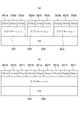
- FIG. 3 is a diagram schematically showing a hierarchical structure of software used in the sensor device of the present embodiment.
- FIG. 4 is a diagram illustrating a configuration of the management server in the watching system according to the present embodiment.
- FIG. 5 is a diagram illustrating a configuration of the mobile terminal in the watching system according to the present embodiment.
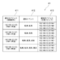
- FIG. 6 is a diagram illustrating a configuration of a transmission destination information table in the watching system according to the present embodiment.
- care is a concept including “nursing”.
- An OS Operating System
- applications, and processes are collectively referred to as software.
- the watching system in the present embodiment is a function for supporting care by watching the target person Ob by detecting the state of the monitored person (hereinafter referred to as the target person) Ob that is the watching target by the corresponding sensor box SB. It is what has.
- Such a monitoring system MS includes, for example, as shown in FIG. 1, a sensor box SB (SB-1 to SB-4), a management server SV, and a fixed terminal device SP respectively provided in the subject person's room.
- Mobile terminals TA (TA-1, TA-2) managed by caregivers, which are wired or wireless, such as LAN (Local Area Network), telephone network and data communication network (network The communication line) is communicably connected via the NW.
- a network (here, referred to as a local network) NW may be provided with a repeater such as a repeater, a bridge, a router, and a cross-connect that relays communication signals.
- a repeater such as a repeater, a bridge, a router, and a cross-connect that relays communication signals.
- the plurality of sensor boxes SB-1 to SB-4, the management server SV, the fixed terminal device SP, and the plurality of portable terminals TA-1 and TA-2 are connected to a wireless LAN (including an access point AP (for example, a LAN conforming to the IEEE 802.11 standard) is connected to be communicable with each other via an NW.
- the sensor box SB corresponds to an example of a sensor device
- each of the fixed terminal device SP and the mobile terminal TA corresponds to an example of a terminal.
- the management server SV is connected to a wide area network GNW such as the Internet by wire or wireless
- a monitor device MD is connected to the wide area network GNW.
- the target person Ob is, for example, a person who needs nursing due to illness or injury, a person who needs care due to a decrease in physical ability, or a single person living alone.
- the subject Ob is a person who needs the detection when a predetermined inconvenient event such as an abnormal state occurs in the person.
- the watching system MS is suitably disposed in a building such as a hospital, a welfare facility for the elderly, and a dwelling unit according to the type of the subject Ob.
- the watching system MS is disposed in a nursing facility building including a plurality of rooms RM in which a plurality of target persons Ob and a plurality of rooms such as a nurse station ST.
- the sensor box SB is disposed on the ceiling or wall of the living room RM of the subject Ob, and has a communication function for communicating with the management server SV or the like via the network NW. More specifically, as shown in FIG. 2, the sensor box SB includes a sensor unit 11, an SB sound input / output unit 12, a nurse call input unit 13, an SB control processing unit 14, and an SB communication IF unit 15. SB storage unit 16.
- the sensor unit 11 is a device that is connected to the SB control processing unit 14, detects the state of the subject Ob under the control of the SB control processing unit 14, and outputs corresponding state data.
- the state of the subject Ob is the wake-up, getting out of bed, falling, falling, and abnormal movement of the subject Ob, and in order to detect these, the sensor unit 11 is, for example, a Doppler sensor 111 And a camera 112.
- the Doppler sensor 111 is a body motion sensor that transmits a transmission wave, receives a reflection wave of the transmission wave reflected by an object, and outputs a Doppler frequency component Doppler signal based on the transmission wave and the reflection wave. .
- the Doppler sensor 111 generates a signal of the Doppler frequency component as a Doppler signal and outputs it to the SB control processing unit 14.
- the transmission wave may be an ultrasonic wave, a microwave, or the like, but is a microwave in the present embodiment. Since the microwave can be transmitted through the clothing and reflected from the body surface of the subject Ob, it is preferable because the motion of the body surface can be detected even if the subject Ob is wearing clothes.
- the camera 112 is an apparatus that is connected to the SB control processing unit 14 and generates an image (image data) under the control of the SB control processing unit 14.
- the camera 112 is arranged so as to be able to monitor a space where the subject Ob to be monitored is located (in the example shown in FIG. 1, a space in the room RM), and images the space as an imaging target from above, An image (image data) overlooking the imaging target is generated, and the image of the imaging target is output to the SB control processing unit 14.
- the camera 112 is set in advance so that the head of the subject Ob is located in the bedding on which the subject Ob is lying (for example, a bed).
- the sensor box SB uses the camera 112 of the sensor unit 11 to acquire an image of the subject Ob taken from above the subject Ob, preferably an image taken from directly above the planned head position.
- Such a camera 112 may be a device that generates an image of visible light, but has a function of generating an infrared image in this embodiment so that the subject Ob can be monitored even in a relatively dark place.
- a camera 112 is, for example, in this embodiment, an imaging optical system that forms an infrared optical image of an imaging target on a predetermined imaging surface, and a light receiving surface that is aligned with the imaging surface.
- An image sensor that converts an infrared optical image in the imaging target into an electrical signal, and image data that is data representing an infrared image in the imaging target by performing image processing on the output of the image sensor.
- a digital infrared camera including an image processing unit to be generated.
- the imaging optical system of the camera 112 is preferably a wide-angle optical system (so-called wide-angle lens (including a fisheye lens)) having an angle of view that can capture the entire room RM of the subject Ob.
- a wide-angle optical system so-called wide-angle lens (including a fisheye lens)
- an infrared illumination device that illuminates the space with infrared light may be further provided.
- the SB sound input / output unit 12 is a circuit that is connected to the SB control processing unit 14 to acquire an external sound and input it to the sensor box SB, and represents an electric signal representing the sound according to the control of the SB control processing unit 14 This generates and outputs sound according to the sound.
- the SB sound input / output unit 12 includes, for example, a microphone that converts sound acoustic vibrations into electrical signals, and a speaker that converts sound electrical signals into sound acoustic vibrations.
- the SB sound input / output unit 12 outputs an electric signal representing an external sound to the SB control processing unit 14, and converts the electric signal input from the SB control processing unit 14 into an acoustic vibration of sound and outputs the sound.
- the SB sound input / output unit 12 can be separated from the sensor box SB main body, and is preferably connected to the SB control processing unit 14 wirelessly or by wire and placed in an arbitrary place in the living room. Furthermore, when the SB sound input / output unit 12 is connected to the SB control processing unit 14 wirelessly, it is preferable to provide a device that monitors the remaining battery capacity in the SB sound input / output unit 12 and notifies the operator or the like. When the SB sound input / output unit 12 is connected to the SB control processing unit 14 by wire, it is preferable to provide a device for notifying an operator or the like whether or not an appropriate connection has been made.
- the nurse call input unit 13 is a push button switch or the like connected to the SB control processing unit 14.
- an electrical signal indicating that the nurse call has been accepted is output from the nurse call input unit 13 to the SB control processing unit 14, thereby A signal is transmitted to the portable terminal TA such as a craftsman.
- a signal is being transmitted, for example, by lighting a lamp associated with the nurse call input unit 13.
- the SB communication IF unit 15 is a communication circuit that is connected to the SB control processing unit 14 and performs communication according to the control of the SB control processing unit 14.
- the SB communication IF unit 15 generates a communication signal containing data to be transferred input from the SB control processing unit 14 in accordance with a communication protocol used in the network NW of the monitoring system MS, and generates the generated communication signal on the network. It transmits to management server SV etc. via NW.
- the SB communication IF unit 15 receives a communication signal from the management server SV or the like via the network NW, extracts data from the received communication signal, and can process the extracted data by the SB control processing unit 14. And output to the SB control processing unit 14.
- the SB communication IF unit 15 further uses a standard such as a mobile phone communication network, WiFi standard, Bluetooth (registered trademark) standard, IrDA (Infrared Data Association) standard, USB (Universal Serial Bus) standard, etc.
- a standard such as a mobile phone communication network, WiFi standard, Bluetooth (registered trademark) standard, IrDA (Infrared Data Association) standard, USB (Universal Serial Bus) standard, etc.
- An interface circuit for inputting / outputting data to / from the device may be provided.
- the SB storage unit 16 is a circuit that is connected to the SB control processing unit 14 and stores various programs (OS, applications, processes, etc. described later) and various data according to the control of the SB control processing unit 14.
- the various programs include, for example, a control processing program such as a monitoring processing program that executes information processing related to monitoring of the subject Ob.
- the monitoring processing program includes a notification processing program for notifying the outside when a predetermined event (event) occurs, an image (moving image) captured by the camera 112, and the fixed terminal device SP or mobile terminal TA that requested the image.
- a nurse call processing program for making a voice call with the fixed terminal device SP and the portable terminal TA by using the SB sound input / output unit 12 and the like.
- the various types of data include data necessary for executing each program, target data Ob, in addition to moving image data captured by the camera 112, state data such as micromotion data acquired by the Doppler sensor 111, and the like. Data necessary for monitoring is included.
- the SB storage unit 16 includes, for example, a ROM (Read Only Memory) that is a nonvolatile storage element, an EEPROM (Electrically Erasable Programmable Read Only Memory) that is a rewritable nonvolatile storage element, and the like.
- the SB storage unit 16 includes a RAM (Random Access Memory) that serves as a working memory of the so-called SB control processing unit 14 that stores data generated during execution of the program.
- the SB control processing unit 14 is a circuit for receiving a nurse call, generating a moving image, and detecting a predetermined action set in advance in the target person Ob.
- the SB control processing unit 14 includes, for example, a CPU (Central Processing Unit) and its peripheral circuits.
- Various software that controls the SB control processing unit 14 is modularized to form a hierarchical structure. Specifically, as shown in FIG. 3A, a plurality of applications 501, 502, and 503 operate on the OS 500 in the SB control processing unit 14, and a plurality of processes 501a to 503c are further executed on each application. Etc. are supposed to work. Alternatively, as shown in FIG.
- a single (or multiple) application 501 operates on the OS 500 in the SB control processing unit 14, and a plurality of processes 501a to 501i and the like operate on the application. It is supposed to be.
- Each application or process may be single, or includes a configuration in which processes are deleted from FIG. 3A and only a plurality of applications are hierarchized on the OS.
- the application 501 is a control application for the camera 112
- the application 502 is a control application for the Doppler sensor 111
- the application 503 is a nurse call input unit. 13 and other control applications.
- a process operated by the application 501 includes a moving image distribution process when an event occurs
- a process operated by the application 502 includes a minute motion data transmission process when an event occurs, which is operated by the application 503.
- the process includes a nurse call processing process when the nurse call is activated.
- the above is an example and can take various forms.
- the SB control processing unit 14 functions as a sensor control unit (SB control unit) 141, a behavior detection processing unit 142, a notification processing unit 143, a streaming processing unit 144, and a nurse call processing unit 145, respectively.
- SB control unit sensor control unit
- Can function an application may be operated independently on a common OS for each function.
- the SB control unit 141 constitutes a monitoring unit and governs overall control of the sensor box SB.
- the “monitoring unit” may be configured by software, may be shared with a circuit that exhibits the above function, or may be configured by hardware such as an independent circuit.
- the behavior detection processing unit 142 detects a predetermined event set in advance in the target person Ob based on the output of the sensor unit 11.
- the predetermined events are the wake-up, getting-off, falling, falling, and abnormal movement of the subject Ob
- the behavior detection processing unit 142 is based on the output of the sensor unit 11. Awakening, getting out of bed, falling, falling, and abnormal movement of the subject person Ob are detected as events and notified to the notification processing unit 143.
- the behavior detection processing unit 142 can detect and detect awakening, getting out of bed, falling, falling, and abnormal movement of the subject Ob.
- the behavior detection processing unit 142 extracts a moving body region as the human body region of the subject person Ob from the image acquired by the camera 112 of the sensor unit 11, and the posture (for example, standing) of the subject person Ob from the aspect ratio of the extracted moving body region. Position, sitting position, lying position, etc.), and detecting the position of the detected moving body region, and determining whether to wake up, get out of bed, fall, and fall based on these determinations and the detected posture and position of the subject Ob. . Further, the behavior detection processing unit 142 determines that a wake-up event (wake-up event) has occurred when a transition from a lying posture to a sitting posture is detected in the bed area.
- a wake-up event wake-up event
- the behavior detection processing unit 142 determines that the person has left the bed and determines that a bed leaving event (a bed leaving event) has occurred. In addition, when the behavior detection processing unit 142 detects a lying posture outside the bed region from the bed region to the outside of the bed region, the behavior detection processing unit 142 determines that the vehicle has fallen, and a fall event (fall event) has occurred. to decide.
- the behavior detection processing unit 142 determines that a fall has occurred and determines that a fall event (fall event) has occurred. Further, the behavior detection processing unit 142 detects body movement of the chest (vertical movement of the chest) accompanying the breathing motion of the subject Ob by the Doppler sensor 111 of the sensor unit 11, and a period disturbance in the body movement of the chest or a pre- When the amplitude in the body movement of the chest that is equal to or less than a set threshold is detected, it is determined that the minute movement abnormality is present, and it is determined that a minute movement abnormality event (fine movement abnormality event) has occurred.
- the behavior detection processing unit 142 has a function of making a determination based on the stored daily behavior of the subject, and when taking a behavior different from the stored normal behavior or taking a behavior due to the stored dementia, etc. For example, it may be determined that an abnormal event has occurred, and the mobile terminal TA may be notified as will be described later.
- the judgment standard (judgment algorithm) of the action detection processing unit 142 is unified for all sensor boxes SB. Thereby, even if a resident changes, it becomes unnecessary to change a judgment standard, and it does not take time and effort.
- the determination criterion of the behavior detection processing unit 142 may be customized for each sensor box SB.
- the nurse call processing unit 145 When the nurse call input unit 13 receives an input operation, the nurse call processing unit 145 notifies the notification processing unit 143 of an event, more specifically, a nurse call operation (nurse call event).
- the nurse call processing unit 145 enables voice communication with the fixed terminal device SP or the portable terminal TA via the SB communication IF unit 15 and the network NW.
- the notification processing unit 143 includes a nurse call event by the nurse call input unit 13 and a predetermined event in which a predetermined action in the target person Ob is detected by the sensor unit 11 (in this embodiment, each event of getting up, getting out of bed, falling, falling) ) Is notified to the outside when it occurs in the sensor box SB. More specifically, the notification processing unit 143 identifies information indicating the type of event that has occurred (in this embodiment, a nurse call event, or a predetermined detection event (wake-up, getting out of bed, falling, falling, falling and abnormal movement of the minute body).
- a notification signal including information, that is, information indicating a type of a predetermined state and the type), and identifier information for identifying and identifying the sensor box SB detecting the subject Ob, and generating SB communication It is transmitted from the IF unit 15 to the management server SV via the network NW. If there is a request (transmission of a status data request signal) from the outside, the notification processing unit 143 communicates a status signal such as image data. Is transmitted from the SB communication IF unit 15 to the management server SV via the network NW.
- the streaming processing unit 144 is provided when a streaming video distribution request is received from the fixed terminal device SP or the portable terminal TA via the network NW and the SB communication IF unit 15. Distributing a moving image (for example, a live moving image) generated by the camera 112 of the sensor unit 11 to the requesting fixed terminal device SP or portable terminal TA via the SB communication IF unit 15 and the network NW by streaming reproduction It is.
- a moving image for example, a live moving image
- FIG. 1 shows four first to fourth sensor boxes SB-1 to SB-4 as an example, and the first sensor box SB-1 is one of the subjects Ob, Mr. Ob.
- the second sensor box SB-2 is arranged in the room RM-2 of Mr. B Ob-2 who is one of the subjects Ob, and the third sensor box SB-3. Is arranged in the room RM-3 of Mr. C Ob-3 who is one of the subject Ob, and the fourth sensor box SB-4 is the room RM of Mr. D Ob-4 who is one of the subject Ob. -4.
- the sensor unit 11 when the operation is started, the sensor unit 11 outputs an image generated by imaging the location space from above at a predetermined frame rate and a Doppler signal to the SB control processing unit 14.
- the behavior detection processing unit 142 of the SB control processing unit 14 detects the presence / absence of a predetermined behavior in the subject Ob based on these images and Doppler signals at predetermined time intervals, and detects the predetermined behavior as a detection event.
- the detection event is notified to the notification processing unit 143 including the type of the detection event.
- the notification processing unit 143 transmits a notification signal from the SB communication IF unit 15 to the management server SV.
- the nurse call processing unit 145 when the nurse call processing unit 145 receives an input operation by the nurse call input unit 13, the nurse call processing unit 145 notifies the notification processing unit 143 of a nurse call reception event. Upon receiving the notification of the reception event, the notification processing unit 143 transmits a notification signal from the SB communication IF unit 15 to the management server SV. The management server SV notifies the mobile terminal TA of the caregiver in charge of the room where the nurse call has occurred that the nurse call has occurred.
- the management server SV communicates independently with another sensor box SB, a fixed terminal SP, a portable terminal TA, and further with a monitor device MD via a wide area network GNW via a network NW. It has a function.
- the management server SV has a function of receiving information from the sensor box SB and providing information to the mobile terminal TA and / or the fixed terminal device SP of the caregiver in charge of the room where the event has occurred.
- a management server SV includes an SV control processing unit 21, an SV storage unit 22, and an SV communication IF unit 23.
- the SV communication IF unit 23 is a communication device that is connected to the SV control processing unit 21 and performs communication according to the control of the SV control processing unit 21.
- the SV communication IF unit 23 generates a communication signal containing data to be transferred input from the SV control processing unit 21 according to a communication protocol used in the network NW of the watching system MS, and generates the generated communication signal on the network. It transmits to sensor box SB etc. via NW.
- the SV communication IF unit 23 receives a communication signal from the sensor box SB or the like via the network NW, extracts data from the received communication signal, and has a format in which the SV control processing unit 21 can process the extracted data. And output to the SV control processing unit 21.
- the SV storage unit 22 is a circuit that is connected to the SV control processing unit 21 and stores various programs and various data in accordance with the control of the SV control processing unit 21.
- the various programs include, for example, a control processing program such as a server program that provides data to the client in response to a request from a client (in this embodiment, the fixed terminal device SP and the portable terminal TA).
- the various types of data include data necessary for executing each program described above, such as monitoring information related to monitoring of the target person Ob and notification destination information related to the event notification destination, and necessary for monitoring the target person Ob. Data.
- the SV storage unit 22 includes, for example, a ROM, an EEPROM, and the like.
- the SV storage unit 22 includes a RAM serving as a working memory for the so-called SV control processing unit 21 that stores data generated during execution of the predetermined program.
- the SV storage unit 22 stores OS, application, and process software programs in association with the sensor boxes SB-1 to SB-4.
- the SV storage unit 22 includes a notification destination information storage unit 221 that stores notification destination information.
- the notification destination information storage unit 221 stores notification destination information related to an event notification destination.
- the notification destination information is information representing a notification destination that notifies the event accommodated in the received notification signal.
- the notification destination information is information indicating a correspondence relationship between the sensor box SB that has transmitted the notification signal and the mobile terminal TA that transmits the notification signal received from the sensor box SB.
- it is stored in the notification destination information storage unit 221 in a table format.
- the 6 includes a notification source address field 411 for registering the communication address of the sensor box SB that is the transmission source of the notification signal, and notification event information when the target person enters this state.
- a notification event field 412 to be notified and an event contained in the notification signal received from the sensor box SB having the communication address associated with the communication address of the sensor box SB registered in the notification source address field 411 are notified.
- a notification destination address field 413 for registering the communication address of the portable terminal TA, and each sensor box SB has a record.
- the communication address of the sensor box SB may be the sensor ID, and the notification source address field 411 is not necessarily provided, but in the case of providing, the room number in which the sensor box SB is provided is registered. Also good.
- the communication address of the mobile terminal TA may be a terminal identifier (terminal ID) for identifying and identifying the mobile terminal TA
- the notification destination address field 413 includes, for example, the name of a caregiver having the mobile terminal TA
- the name of a monitor such as may be registered.
- a notification event item (notification event information) in the notification event field 412 can be set from the management server SV side according to the target person Ob in the room where the sensor box SB is installed.
- notification event item (notification event information) in the notification event field 412 can be set from the management server SV side according to the target person Ob in the room where the sensor box SB is installed.
- notification should be made when a fall / fall event occurs
- Mr. C notification should be given if a fall / fall / wake event occurs.
- the condition of the target person (there is almost no problem after getting up, there are people who can be judged to be unnecessary, there is a person who is not), past correspondence information (having the habit of repeating getting out and getting up several times in the past) Therefore, it is desirable to divide the notification event according to the target person for reasons such as that there is a person who can determine that it is not necessary to take a single bed.
- the SV control processing unit 21 is a circuit that receives a notification from the sensor box SB and transfers the received notification to the fixed terminal device SP and the corresponding mobile terminal TA.
- the SV control processing unit 21 includes a CPU (Central Processing Unit) and its peripheral circuits.
- the SV control unit 211 of the SV control processing unit 21 is responsible for overall control of the management server SV.
- the management server SV is connected to the SV control processing unit 21 as necessary, as shown by a broken line in FIG. 4, for example, a server input unit (SV input unit) 24 for inputting various commands, various data, and the like.
- An interface unit (SVIF unit) 26 and the like may be provided.
- Such a management server SV can be configured by a computer with a communication function, for example.
- the fixed terminal device SP is installed in the nurse station ST and has a communication function for communicating with the management server SV and the like via the network NW, a display function for displaying predetermined information, and an input for inputting predetermined instructions and data.
- the user interface of the watching system MS is provided by inputting predetermined instructions and data given to the management server SV and the portable terminal TA, and displaying detection results and images obtained by the sensor box SB.
- Such a fixed terminal device SP can be configured by, for example, a computer with a communication function. It is preferable that the fixed terminal device SP can grasp the state of the room through the function of the sensor box SB in all the rooms in which the sensor box SB is installed.
- the portable terminal TA has a communication function for communicating with the management server SV and the like via the network NW, a display function for displaying predetermined information, an input function for inputting predetermined instructions and data, a call function for performing a voice call, and the like.
- a predetermined instruction or data to be given to the management server SV or the sensor box SB is input, and when the predetermined event occurs in the sensor box SB, the notification of the predetermined event is received and a call is made with the sensor box SB.
- such a portable terminal TA includes a TA control processing unit 31, a TA storage unit 32, a TA communication IF unit 33, a TA sound input / output unit 34, A TA input unit 35, a TA display unit 36, and a TAIF unit 37 are provided.
- the TA sound input / output unit 34 is a device connected to the TA control processing unit 31 for acquiring external sound and inputting it to the mobile terminal TA.
- the TA sound input / output unit 34 represents an electric signal representing the sound according to the control of the TA control processing unit 31. This generates and outputs sound according to the sound.
- the TA sound input / output unit 34 includes, for example, a microphone or the like that converts acoustic vibration into an electric signal, and a speaker or the like that converts an electric signal of sound into an acoustic vibration of sound. Composed.
- the TA sound input / output unit 34 outputs an electrical signal representing an external sound to the TA control processing unit 31, and converts the electrical signal input from the TA control processing unit 31 into sound acoustic vibration and outputs the sound.
- the TA input unit 35 is connected to the TA control processing unit 31 and is, for example, a device that receives a predetermined operation and inputs it to the mobile terminal TA, and includes a plurality of input switches assigned a predetermined function.
- the predetermined operation include an ID input operation for logging in, a response operation corresponding to the notified nurse call, a request operation for a moving image, and a life-saving, nursing, and care for the notified subject Ob, for example.
- various operations necessary for monitoring such as an input operation indicating that there is an intention to execute a response such as assistance (restoration).
- the TA display unit 36 which is an information presentation unit is connected to the TA control processing unit 31 and monitored by the monitoring system MS according to the predetermined operation content input from the TA input unit 35 according to the control of the TA control processing unit 31.
- This is a device that displays the monitoring information (for example, an event that occurred in the sensor box SB, an image of the subject Ob, etc.) related to the monitoring of the subject Ob, and is a display device such as an LCD and an organic EL display.
- the TA input unit 35 and the TA display unit 36 are configured from a touch panel.
- the TA input unit 35 is a position input device that detects and inputs an operation position such as a resistance film method or a capacitance method.
- a position input device is provided on the display surface of the TA display unit 36, and one or more input content candidates that can be input are displayed on the TA display unit 36.
- a user such as a caregiver (monitorer)
- the position is detected by the position input device, and the display content displayed at the detected position is input to the portable terminal TA as the operation input content of the user.
- the TAIF unit 37 is a device that is connected to the TA control processing unit 31 and performs data input / output with an external device under the control of the TA control processing unit 31.
- the TAIF unit 37 is a mobile phone communication network, WiFi standard, Bluetooth, and the like.
- the TA communication IF unit 33 is a communication device that is connected to the TA control processing unit 31 and performs communication according to the control of the TA control processing unit 31, similarly to the SB communication IF unit 15.
- the TA communication IF unit 33 generates a communication signal containing data to be transferred input from the TA control processing unit 31 according to a communication protocol used in the network NW of the monitoring system MS, and generates the generated communication signal on the network. It transmits to management server SV etc. via NW.
- the TA communication IF unit 33 receives a communication signal from the management server SV or the like via the network NW, extracts data from the received communication signal, and has a format in which the TA control processing unit 31 can process the extracted data. And output to the TA control processing unit 31.
- the TA storage unit 32 is a circuit that is connected to the TA control processing unit 31 and stores various programs and various data according to the control of the TA control processing unit 31, similarly to the SB storage unit 16.
- the various programs include a display processing program for processing operations related to display.
- the various data includes data such as screen information displayed on the TA display unit 36.
- the TA storage unit 32 includes, for example, a ROM and an EEPROM.
- the TA storage unit 32 includes a RAM that serves as a working memory of a so-called TA control processing unit 31 that stores data generated during execution of the predetermined program.
- the TA storage unit 32 functionally includes a display screen storage unit 321 in order to store the above-described information.
- the display screen storage unit 321 stores screen information to be displayed on the TA display unit 36 in accordance with the control of the display processing unit 3121 described later in the TA control processing unit 31.
- the TA control processing unit 31 is a circuit for processing information. Similar to the SB control processing unit 14, the TA control processing unit 31 includes, for example, a CPU and its peripheral circuits.
- the TA control processing unit 31 functionally includes a TA control unit 311 and a TA processing unit 312 by executing a control processing program, and the TA processing unit 312 functionally includes a display processing unit 3121.
- the TA control unit 311 is responsible for overall control of the mobile terminal TA.
- the display processing unit 3121 processes an operation related to the display of the TA display unit 36. More specifically, the display processing unit 3121 displays a moving image on the TA display unit 36 as necessary.
- Such a portable terminal TA can be constituted by a portable communication terminal device such as a so-called tablet computer, a smartphone, or a mobile phone.
- FIG. 7 is a ladder chart diagram showing a control operation in the watching system of the present embodiment.
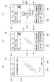
- FIG. 8 is a diagram illustrating an example of a display screen of the mobile terminal according to the present embodiment.
- the SB control processing unit 14 includes the SB control unit 141, the action detection.
- the processing unit 142, the notification processing unit 143, the streaming processing unit 144, and the nurse call processing unit 145 are functionally configured.
- the SV control processing unit 21 is functionally configured by executing the control processing program, and in the portable terminal TA, the TA is executed by executing the control processing program.
- a TA processing unit 312 functionally including a TA control unit 311 and a display processing unit 3121 is functionally configured.
- the portable terminal TA When the portable terminal TA accepts a login operation such as a caregiver, for example, the portable terminal TA causes the TA processing unit 312 to display a standby screen waiting for a communication signal addressed to itself on the TA display unit 36.
- the standby screen includes a menu bar area 611 for displaying a menu bar, a message indicating that the standby is in progress (for example, “There is no unsupported notification”), date and current A standby main area 612 for displaying a time, a user name (caregiver) who logs in the portable terminal TA, and the like.
- the portable terminal TA waits for the TA communication IF unit 33 to receive a communication signal by the TA control unit 311.
- step S101 of FIG. 7 the sensor box SB samples the output data of the Doppler sensor 111 of the sensor unit 11 at a sampling period corresponding to a predetermined frame rate by the SB control unit 141 and acquires image data by the camera 112.
- the behavior detection processing unit 142 analyzes the sampled and acquired output data of the Doppler sensor 111 and the image data of the camera 112 while being stored in a ring buffer (not shown).
- a predetermined event wake-up, getting-off, falling, falling, falling, or minute body movement abnormality
- the SB control unit 141 detects a predetermined event
- the image data and / or minute motion data before and after the event are cut out from the ring buffer and stored in the SB storage unit 16 in step S103.
- the detection operation of the sensor box SB can be interrupted only during the time period set via the fixed terminal SP.
- the program in the sensor box SB can be changed via the fixed terminal SP.
- the sensor box SB transmits event information indicating which type of notification event has occurred and a notification signal including a communication address to the management server SV via the network NW by the notification processing unit 143 (C11). Since the notification signal does not include the image data of the subject person, the amount of information is small.
- the management server SV sends the information included in the notification signal to the notification destination information table 41 stored in the notification destination information storage unit 221 in step S104.
- the resident here, Mr. B
- the resident Mr. B
- the event information of the notification signal It is determined whether it corresponds to the type of the corresponding notification event (here, falling or falling).
- the event information of the received notification signal indicates a notification event, it is determined to notify the terminal.
- the event information of the received notification signal does not indicate a notification event (in the case of Mr. B, wakes up or leaves), it is determined not to notify the terminal and waits for the next notification signal.
- the management server SV compares the notification destination information table 41 stored in the notification destination information storage unit 221 with the communication address of the transmission destination corresponding to the communication address of the transmission source.
- a destination mobile terminal TA is selected. More specifically, in the notification destination information table 41 stored in the notification destination information storage unit 221, the notification in the record in which the communication address of the transmission source of the received notification signal is registered in the notification source address field 411. The communication address of the notification destination registered in the destination address field 413 is extracted.
- the communication address “192.168.10.25” is a communication address assigned to the portable terminal TA-1 owned by the caregiver NA, and the communication address “192.168.10.26”. Is the communication address assigned to the mobile terminal TA-2 owned by the caregiver NB, and the communication address "192.168.10.27" is the mobile terminal TA- 3 is a communication address assigned to the network.
- the management server SV transmits a notification signal (event signal, that is, a watch alarm) including information that the fall or the fall has occurred in the RM-2 room to the selected portable terminals TA-1 to TA-3 and the fixed terminal SP. (C12).
- a notification signal event signal, that is, a watch alarm
- the portable terminal TA When such a notification signal is transmitted from the management server SV, the portable terminal TA switches the screen display of the TA display unit 36 to, for example, the one shown in FIG. At this time, the TA sound input / output unit 34 serving as a presentation unit is used to output sounds and voices (for example, a voice message such as “falling in RM-2”) or to the caregiver by vibration or the like. The reception of the notification signal may be notified.
- buttons B1 corresponding), B2 (speak), B3 (view stored video), and B4 (view live video) are displayed in the main area 612.
- the TA control unit 311 determines that an image request has been made, and the TA communication IF unit
- a request signal (status data request signal) is transmitted to the management server SV via the network NW (C13).
- the request signal includes a request type (stored video or live video).
- the management server SV relays the request signal and transmits it to the target sensor box SB.
- the request signal may be transmitted directly to the sensor box SB.
- the sensor box SB that has received the request signal determines the request type in the request signal in step S107.
- a request signal for requesting a stored image is output from the portable terminal TA. Therefore, the sensor box SB that has received the request via the management server SV requests a stored image.
- the image data is read from the SB storage unit 16 and transmitted from the SB communication IF unit 15 to the management server SV via the network NW (C14).
- NW NW
- the caregiver touches the button B4 a request signal for requesting a live image is output from the portable terminal TA, and the sensor box SB that has received the request via the management server SV is requested for the live image.
- step S108 the live video imaged by the camera 112 is encoded and transmitted from the SB communication IF unit 15 to the management server SV via the network NW (C14).
- the live video may be cut out from the ring buffer.
- the management server SV transmits the image data to the portable terminal TA that has transmitted the request signal. Note that the image data may be transmitted directly to the portable terminal TA.
- the mobile terminal TA that has received the image data switches the screen display of the TA display unit 36 to the one shown in FIG.
- the image (video) IMG of Mr. B before and after falling down in the RM-2 room is displayed in the main area 612.
- the person can immediately determine whether or not the state should be dealt with.
- the caregiver can touch the button B2 so that Mr. B and the caregiver can directly talk via the SB sound input / output unit 12 of the sensor box SB.
- the situation can be judged accurately.
- the image displayed on the portable terminal TA is the current streaming image.
- the notification signal is transmitted to the portable terminal TA, and / or the notification signal may be transmitted to the fixed terminal SP.
- the image request can be arbitrarily made regardless of the notification signal.
- step S105 when the caregiver who sees the icon IC1 displayed in step S105 is near the RM-2 room where the event occurred, the caregiver can rush immediately without looking at the image. Therefore, in such a case, by touching the button B1, information indicating that the caregiver responds directly is transmitted to the fixed terminal SP. By touching the button B1, the display corresponding to the notification signal is canceled in the other portable terminal TA and / or the fixed terminal SP to which the notification signal is transmitted, and the display returns to the display of FIG. It is preferable that the “caregiver in charge, handling” indication is made.
- FIG. 9 is a diagram showing another display screen example of the mobile terminal.
- the sensor box SB determines that the subject has fallen or falls from the acquired image data and transmits a notification signal to the management server SV.
- a notification signal can be transmitted to the management server SV.
- the notification signal indicating that the micromotion is abnormal is transmitted from the management server SV to the selected mobile terminal TA, and the micromotion is abnormal in the received mobile terminal TA.
- An icon IC2 indicating this may be displayed.
- the caregiver can touch the button B3 to request image transfer (or transfer of minute motion data) in the room, and the caregiver can touch the button B2 to touch the sensor box SB. Since the subject and the caregiver can directly talk via the SB sound input / output unit 12, the situation can be accurately determined.
- the analysis of the image captured by the camera and the state of minute movement detected by the Doppler sensor may be combined and used for event determination.
- FIG. 10 is a diagram illustrating a ladder chart for controlling the monitoring operation.
- the control operation shown in FIG. 10 is preferably executed in parallel with the operation shown in FIG.
- the SB control unit 141 Based on the self-diagnostic program, the SB control unit 141 repeatedly detects at any given timing whether a failure has occurred in any of the currently operating OS, application, and process software.
- the SB control unit 141 identifies the software in which the failure has occurred. It is preferable to specify the fault for each module. Note that “failure” means that correct data or the like is no longer output.
- the SB control unit 141 determines to restart only the process 501a individually. However, if there is a mutually related process, such as when the data output in the process 501a is used in the process 501b, the process 501b is restarted even if there is no failure.
- the SB control unit 141 determines to individually restart the application 501 including the processes 501a to 501c. That is, “restart individually” includes restarting the application including the process when the application having the process is restarted.
- the module may be restarted as a unit.
- the application 503 is restarted even if there is no failure.
- the SB control unit 141 determines that a failure has occurred in the entire OS 500, the SB control unit 141 determines to restart the OS 500.
- step S203 the SB control unit 141 reads the software program to be restarted from the SB storage unit 16, and restarts only the target software. Thereby, the time to recovery can be kept short.
- the applications or processes are sequentially activated in accordance with a predetermined “activation item” setting file.
- the data to be transferred must be It is desirable to store it in a non-volatile memory or the like and use it after restarting.
- the SB control unit 141 determines whether or not the target software has been recovered from the failure.
- the SB control unit 141 includes the details of the failure recovered by the restart and unique identifier information of the sensor box SB (for example, the communication address “192”). .168.10.121 ”or the like (which may be a product number or the like) is transmitted to the management server SV (C21).
- the management server SV associates the content of the failure recovered by the restart with the identifier information of the sensor box SB and stores it in the database in the SV storage unit 22. By constructing such a database, it becomes easier to deal with future failures.
- the SB control unit 141 creates an autonomous recovery impossible message including information of the software that could not be recovered in step S206, and the sensor box of its own Along with the SB identifier information, it is transmitted to the management server SV (C22).
- the management server SV searches the SV storage unit 22 based on the identifier information of the sensor box SB in which the failure has occurred, reads the software program in which the failure has occurred, Is transmitted to the sensor box SB where the error occurs (C23).
- the management server SV can automatically display an “alarm based on an autonomous recovery impossible message” on the monitor of the management server SV without automatically responding. In such a case, the worker who has seen the alarm display can manually read out the software program in which the failure has occurred and send it to the sensor box SB in which the failure has occurred to instruct the restart.
- step S208 the SB control unit 141 overwrites the software program transmitted from the management server SV on the SB storage unit 16, and then restarts only the target software based on the program. As a result, even if the program stored in the SB storage unit 16 has a problem, the software can be appropriately restored.
- step S209 the SB control unit 141 executes the self-diagnosis program again, and determines whether or not the target software has been recovered from the failure.
- the SB control unit 141 transmits the content of the failure recovered by the restart and the identifier information of its own sensor box SB to the management server SV. (C24).
- the management server SV associates the program name used for the restart, the content of the failure recovered by the restart, and the identifier information of the sensor box SB, and stores them in the SV storage unit 22. Store in the database.
- the SB control unit 141 creates a message indicating that the recovery has failed in step S211, and combines it with the identifier information of its own sensor box SB. Is transmitted to the management server SV (C25). In response to this, in step S212, the management server SV issues a warning that a failure has occurred together with the name of the sensor box SB in which the failure has occurred. An operator who sees such an alarm can access the sensor box SB in which the failure has occurred and can perform recovery by appropriate work.
- FIG. 11 is a diagram showing a ladder chart relating to another control of the monitoring operation, which can be performed in parallel with the control of FIG.
- the monitoring unit is in the management server SV or the monitoring device MD
- the control operation shown in FIG. 11 is also preferably performed in parallel with the operations shown in FIGS.
- the SV control unit 211 (or the monitoring device MD) requests data transfer to all sensor boxes SB via the network NW (and the wide area network GNW) at a predetermined timing (C31).
- data includes a self-diagnosis result in the sensor box SB, an operation history, collected state data, and the like.
- the sensor box SB transfers the requested data to the SV control unit 211 (or the monitor device MD) (C32).
- the SV control unit 211 determines whether a failure has occurred in the sensor box SB based on the data transferred from the sensor box SB.
- the SV control unit 211 repeats the above operation until it is determined that a failure has occurred.
- the data transmitted from the sensor box SB to the corresponding portable terminal TA can be temporarily stored in the SV control unit 211 (or the monitor device MD) and analyzed to determine that a failure has occurred. Furthermore, as shown by a dotted line in FIG.
- step S301 If it is determined in step S301 that a failure has occurred in the sensor box SB to which the data has been transferred, the SV control unit 211 (or the monitor device MD) analyzes the transferred data in step S302 to determine the OS, application, and Determine if one of the processes has failed. Thereafter, the SV control unit 211 (or the monitor device MD) transmits an instruction to restart only the software in which the failure has occurred to the sensor box SB in which the failure has occurred (C35). When the SV control unit 211 determines that a failure has occurred in the sensor box SB, an alarm is issued, and an operator in contact with the sensor box manually transmits a “restart” command to the sensor box SB. You can also.
- the SV control unit 211 (or the monitoring device MD) transmits a self-diagnosis instruction to the sensor box SB without specifying the software in which the failure has occurred, and the sensor box SB performs a self-diagnosis so that the failure is detected.
- the software that has occurred may be identified and restarted.
- step S303 the SB control unit 141 of the sensor box SB that has received the instruction from the SV control unit 211 (or the monitor device MD) reads out the software program to be restarted from the SB storage unit 16, and sets the target. Restart only the software. Note that a software program to be restarted may be included in the instruction transmitted from the SV control unit 211 (or the monitor device MD). In such a case, the SB control unit 141 performs restart using the included program.
- the SB control unit 141 executes a self-diagnosis program, checks whether there is a failure in the restarted software, and transmits the diagnosis result to the SV control unit 211 (or the monitor device MD).
- the SV control unit 211 (or the monitor device MD) that has received the diagnosis result determines whether or not the failure of the sensor box SB has been recovered in step S304.
- the SV control unit 211 (or the monitor device MD) obtains the content of the failure recovered by the restart and the identifier information of the sensor box SB in step S306. Correspondingly, it is stored in the database in the SV storage unit 22.
- the SV control unit 211 (or the monitor device MD) indicates that a failure has occurred in step S305 along with the name of the sensor box SB in which the failure has occurred. A warning is issued. An operator who sees such an alarm can access the sensor box SB in which the failure has occurred and can perform recovery by appropriate work.
Landscapes
- Engineering & Computer Science (AREA)
- Signal Processing (AREA)
- Business, Economics & Management (AREA)
- Emergency Management (AREA)
- Physics & Mathematics (AREA)
- General Physics & Mathematics (AREA)
- Alarm Systems (AREA)
- Telephonic Communication Services (AREA)
Abstract
介護士等の負担を減らしつつも、容易且つ迅速に障害からの復旧を行える見守りシステムを提供する。見守り対象者からのデータを入力して、それに応じた信号を出力するセンサ装置と、ネットワークを介して前記センサ装置と通信可能に接続された管理サーバと、前記ネットワークを介して前記センサ装置と通信可能に接続され、前記センサ装置から出力された信号に基づいて警報を出力する端末装置と、を有する見守りシステムは、前記センサ装置は、OS上で1つ以上のアプリケーションが動作するソフトウエアの階層構造を有しており、前記OSと前記アプリケーションの実行状態を監視して、いずれかに障害が生じたことを検出した場合、前記障害が生じたソフトウエアを独立して再起動させる監視部を設けている。
Description
本発明は、介護施設等で好適に用いられる見守りシステムに関する。
我が国においては、国民の平均寿命の伸びや出生率の低下により少子高齢化が急速に進んでいる。これに伴い、介護が必要な者(要介護者)を収容する病院や老人福祉施設等は増大しつつあるが、過酷な勤務状況などの理由で看護師や介護士の人手が慢性的に足りないという深刻な事態を招いている。特に夜間などにおいては、少ない人数で多くの要介護者を見守らなくてはならず、介護士等の負担が大きくなり、これが更なる人手不足を招く一因となっている。
このような介護士等の負担を軽減するため、介護業務を支援する技術が求められている。一例を挙げると、介護士等の仕事の一部を機械に行わせるために、要介護者を監視(モニタ)する種々の技術が開発されている。
特許文献1には、異常検出装置が施設内における監視対象の異常を検出したときに、監視対象の画像を監視装置に備えたカメラで撮像して、ネット等を介して外部の端末へとその画像データを送信することで、監視対象の現状を遠隔的に監視する技術が開示されている。
特許文献1の監視装置を用いれば、要介護者を監視対象とすることで、その無人監視が可能になり、介護士等の負担が減ることになる。ところで、このような監視装置を介護施設等に設置する場合、例えばナースコールなどの付加的機能を設けたいという要請があり、これに応じるためには監視装置の多機能化は避けられない。一方、監視装置が多機能化するにつれ搭載するソフトウエアの数も増大するが、その開発効率を高めるためにソフトウエアのモジュール化が進む結果として、例えばソフトウエア間での不調和等が生じやすくなり、予期せぬ障害が起こる恐れが強まっているという実情がある。ここで、監視装置に何らかの障害が生じた場合、監視洩れが極力生じないように迅速に復旧させる必要があるが、まず、かかる障害をどのように検出するかという問題がある。
これに対し、特許文献2には、アプリケーションの動作状態をモニタすべく、専用のモニタ装置を、ネットワークを介してシステムに追加で導入することによって、前記アプリケーションの動作状態の管理を可能とする技術が開示されている。かかる技術を流用して、監視装置及びこれをモニタするモニタ装置を、ネットワークを介して相互に接続することで、監視装置の障害を遠隔的にモニタすることが可能になる。
しかしながら、専用のモニタ装置を別個に追加することはコストの上昇を招くこととなる。又、監視装置に障害が生じたことをモニタできたとしても、それを復旧させる為に人手を要すると、監視装置の復旧に時間とコストがかかる。更には、障害を監視するためのモニタ装置自体に障害が生じる恐れもあるが、それにより個々の監視装置の障害を監視することができなくなるため問題である。
本発明は、上記事情に鑑みなされたものであり、介護士等の負担を減らしつつも、容易且つ迅速に障害からの復旧を行える見守りシステムを提供することを目的とする。
上述した目的のうち少なくとも一つを実現するために、本発明の一側面を反映した見守りシステムは、
見守り対象者からのデータを入力して、それに応じた信号を出力するセンサ装置と、
ネットワークを介して前記センサ装置と通信可能に接続された管理サーバと、
前記ネットワークを介して前記センサ装置と通信可能に接続され、前記センサ装置から出力された信号に基づいて見守りアラームを出力する端末装置と、を有する見守りシステムであって、
前記センサ装置が、OS上で複数のアプリケーションが動作するソフトウエアの階層構造を有しているときは、前記アプリケーションの実行状態を監視して、いずれかのアプリケーションに障害が生じたことを検出した場合、前記障害が生じたアプリケーションを個別に再起動させ、
また前記センサ装置が、OS上で1つ以上のアプリケーションが動作し、前記アプリケーション上で1つ以上のプロセスが動作するようになっているソフトウエアの階層構造を有しているときは、前記アプリケーション及び前記プロセスの実行状態を監視して、いずれかのアプリケーション又はプロセスに障害が生じたことを検出した場合、前記障害が生じたアプリケーション又はプロセスを個別に再起動させる監視部を設けたものである。
見守り対象者からのデータを入力して、それに応じた信号を出力するセンサ装置と、
ネットワークを介して前記センサ装置と通信可能に接続された管理サーバと、
前記ネットワークを介して前記センサ装置と通信可能に接続され、前記センサ装置から出力された信号に基づいて見守りアラームを出力する端末装置と、を有する見守りシステムであって、
前記センサ装置が、OS上で複数のアプリケーションが動作するソフトウエアの階層構造を有しているときは、前記アプリケーションの実行状態を監視して、いずれかのアプリケーションに障害が生じたことを検出した場合、前記障害が生じたアプリケーションを個別に再起動させ、
また前記センサ装置が、OS上で1つ以上のアプリケーションが動作し、前記アプリケーション上で1つ以上のプロセスが動作するようになっているソフトウエアの階層構造を有しているときは、前記アプリケーション及び前記プロセスの実行状態を監視して、いずれかのアプリケーション又はプロセスに障害が生じたことを検出した場合、前記障害が生じたアプリケーション又はプロセスを個別に再起動させる監視部を設けたものである。
本発明によれば、介護士等の負担を減らしつつも、容易且つ迅速に障害からの復旧を行える見守りシステムを提供することができる。
以下、本発明にかかる実施形態を図面に基づいて説明する。図1は、本実施形態における見守りシステムの全体構成を示す図である。図2は、本実施形態の見守りシステムにおけるセンサボックスの構成を示す図である。図3は、本実施形態のセンサ装置に用いるソフトウエアの階層構造を模式化して示す図である。図4は、本実施形態の見守りシステムにおける管理サーバの構成を示す図である。図5は、本実施形態の見守りシステムにおける携帯端末の構成を示す図である。図6は、本実施形態の見守りシステムにおける送信先情報テーブルの構成を示す図である。本明細書中、「介護」とは「看護」も含む概念である。又、OS(Operating System),アプリケーション、プロセスを総称してソフトウエアと呼ぶ。
本実施形態における見守りシステムは、見守り対象である被監視者(以下、対象者という)Obの状態を、それぞれ対応するセンサボックスSBにより検知することで対象者Obを見守って、介護を支援する機能を有するものである。
このような見守りシステムMSは、例えば、図1に示すように、対象者の居室にそれぞれ備えられたセンサボックスSB(SB-1~SB-4)と、管理サーバSVと、固定端末装置SPと、介護士がそれぞれ管理する携帯端末TA(TA-1、TA-2)とを有し、これらは、有線や無線で、LAN(Local Area Network)、電話網およびデータ通信網等の網(ネットワーク、通信回線)NWを介して通信可能に接続されて構成されている。ネットワーク(ここではローカルネットワークとする)NWには、通信信号を中継する例えばリピーター、ブリッジ、ルーターおよびクロスコネクト等の中継機が備えられても良い。図1に示す例では、これら複数のセンサボックスSB-1~SB-4、管理サーバSV、固定端末装置SPおよび複数の携帯端末TA-1、TA-2は、アクセスポイントAPを含む無線LAN(例えばIEEE802.11規格に従ったLAN等)NWによって互いに通信可能に接続されている。センサボックスSBは、センサ装置の一例に相当し、固定端末装置SPおよび携帯端末TAそれぞれは、端末の一例に相当する。管理サーバSVは、インターネットなどの広域ネットワークGNWに有線又は無線で接続されており、また広域ネットワークGNWにモニタ装置MDが接続されている。
対象者Obは、例えば、病気や怪我等によって看護を必要とする者や、身体能力の低下等によって介護を必要とする者や、一人暮らしの独居者等である。特に、早期発見と早期対処とを可能にする観点から、対象者Obは、例えば異常状態等の所定の不都合な事象がその者に生じた場合にその発見を必要としている者であることが好ましい。このため、見守りシステムMSは、対象者Obの種類に応じて、病院、老人福祉施設および住戸等の建物に好適に配設される。図1に示す例では、見守りシステムMSは、複数の対象者Obが入居する複数の居室RMや、ナースステーションST等の複数の部屋を備える介護施設の建物に配設されている。
まず、センサボックスSBについて説明する。センサボックスSBは、対象者Obの居室RMの天井や壁等にそれぞれ配置され、ネットワークNWを介して管理サーバSV等と通信する通信機能を備えている。より具体的に、センサボックスSBは、図2に示すように、センサ部11と、SB音入出力部12と、ナースコール入力部13と、SB制御処理部14と、SB通信IF部15と、SB記憶部16とを備える。
センサ部11は、SB制御処理部14に接続され、SB制御処理部14の制御に従って、対象者Obの状態を検知して、対応する状態データを出力する装置である。本実施形態では、対象者Obの状態としては、対象者Obの起床、離床、転倒、転落および微体動異常であり、これらを検知するために、センサ部11は、例えば、ドップラセンサ111と、カメラ112とを備える。
ドップラセンサ111は、送信波を送信し、物体で反射した前記送信波の反射波を受信し、前記送信波と前記反射波とに基づいてドップラ周波数成分のドップラ信号を出力する体動センサである。前記物体が動いている場合、いわゆるドップラ効果により前記物体の動いている速度に比例して反射波の周波数がシフトするため、送信波の周波数と反射波の周波数とに差(ドップラ周波数成分)が生じる。ドップラセンサ111は、このドップラ周波数成分の信号をドップラ信号として生成し、SB制御処理部14へ出力するものである。前記送信波は、超音波やマイクロ波等であって良いが、本実施形態では、マイクロ波である。マイクロ波は、着衣を透過して対象者Obの体表で反射できるため、対象者Obが衣服を着ていても体表の動きを検知でき、好ましい。
カメラ112は、SB制御処理部14に接続され、SB制御処理部14の制御に従って、画像(画像データ)を生成する装置である。カメラ112は、監視すべき対象者Obが所在を予定している空間(図1に示す例では居室RM内の空間)を監視可能に配置され、前記空間を撮像対象としてその上方から撮像し、前記撮像対象を俯瞰した画像(画像データ)を生成し、前記撮像対象の画像をSB制御処理部14へ出力する。好ましくは、対象者Ob全体を撮像できる蓋然性が高いことから、カメラ112は、対象者Obが横臥する寝具(例えばベッド等)における、対象者Obの頭部が位置すると予定されている予め設定された頭部予定位置(通常、枕の配設位置)の直上から撮像対象を撮像できるように配設される。センサボックスSBは、このセンサ部11のカメラ112によって、対象者Obを、対象者Obの上方から撮像した画像、好ましくは前記頭部予定位置の直上から撮像した画像を取得する。
このようなカメラ112は、可視光の画像を生成する装置であって良いが、比較的暗がりでも対象者Obを監視できるように、本実施形態では、赤外線の画像を生成する機能を有する。このようなカメラ112は、例えば、本実施形態では、撮像対象における赤外の光学像を所定の結像面上に結像する結像光学系、前記結像面に受光面を一致させて配置され、前記撮像対象における赤外の光学像を電気的な信号に変換するイメージセンサ、および、イメージセンサの出力を画像処理することで前記撮像対象における赤外の画像を表すデータである画像データを生成する画像処理部等を備えるデジタル赤外線カメラである。カメラ112の結像光学系は、本実施形態では、対象者Obの居室RM全体を撮像できる画角を持つ広角な光学系(いわゆる広角レンズ(魚眼レンズを含む))であることが好ましい。また、前記空間を赤外線で照明する赤外線照明装置がさらに設けられても良い。
SB音入出力部12は、SB制御処理部14に接続され、外部の音を取得してセンサボックスSBに入力するための回路であって、SB制御処理部14の制御に従って音を表す電気信号に応じた音を生成して出力するものである。SB音入出力部12は、例えば、音の音響振動を電気信号に変換するマイクロホン等と、音の電気信号を音の音響振動に変換するスピーカ等とを備えて構成される。SB音入出力部12は、外部の音を表す電気信号をSB制御処理部14へ出力し、また、SB制御処理部14から入力された電気信号を音の音響振動に変換して出力する。尚、SB音入出力部12はセンサボックスSB本体と分離でき、SB制御処理部14に無線もしくは有線で接続され、居室内の任意の場所に置かれるようになっていると好ましい。更に、SB音入出力部12をSB制御処理部14に無線で接続する場合、SB音入出力部12内の電池残量をモニタして操作者等に知らせる装置を設けるのが好ましい。又、SB音入出力部12をSB制御処理部14に有線で接続する場合、適切な接続が行われているか否かを操作者等に知らせる装置を設けるのが好ましい。
ナースコール入力部13は、SB制御処理部14に接続された押しボタン式スイッチ等である。居住者がナースコールしたい場合に、ナースコール入力部13が入力操作されると、ナースコールを受け付けた旨を示す電気信号がナースコール入力部13からSB制御処理部14へ出力され、これにより介護士等の携帯端末TAに信号が送信される。このとき、ナースコール入力部13に付随したランプが点灯するなどして、信号送信中であることが分かると好ましい。
SB通信IF部15は、SB制御処理部14に接続され、SB制御処理部14の制御に従って通信を行うための通信回路である。SB通信IF部15は、SB制御処理部14から入力された転送すべきデータを収容した通信信号を、この見守りシステムMSのネットワークNWで用いられる通信プロトコルに従って生成し、この生成した通信信号をネットワークNWを介して管理サーバSV等へ送信する。又、SB通信IF部15は、ネットワークNWを介して管理サーバSV等から通信信号を受信し、この受信した通信信号からデータを取り出し、この取り出したデータをSB制御処理部14が処理可能な形式のデータに変換してSB制御処理部14へ出力する。なお、SB通信IF部15は、さらに、例えば、携帯電話通信網、WiFi規格、Bluetooth(登録商標)規格、IrDA(Infrared Data Asscoiation)規格およびUSB(Universal Serial Bus)規格等の規格を用い、外部機器との間でデータの入出力を行うインターフェース回路を備えても良い。
SB記憶部16は、SB制御処理部14に接続され、SB制御処理部14の制御に従って、各種のプログラム(後述するOS,アプリケーション、プロセス等)および各種のデータを記憶する回路である。前記各種のプログラムには、例えば、対象者Obに対する監視に関する情報処理を実行する監視処理プログラム等の制御処理プログラムが含まれる。前記監視処理プログラムには、所定のイベント(事象)が生じた場合に外部に通知する通知処理プログラム、カメラ112で撮像した画像(動画)を、その画像を要求した固定端末装置SPや携帯端末TAへ配信する処理プログラム、および、SB音入出力部12等を用いることで固定端末装置SPや携帯端末TAとの間で音声通話を行うナースコール処理プログラム等が含まれる。前記各種のデータには、カメラ112で撮像した動画のデータや、ドップラセンサ111により取得した微体動データ等の状態データの他、各プログラムを実行する上で必要なデータや、対象者Obを監視する上で必要なデータ等が含まれる。SB記憶部16は、例えば不揮発性の記憶素子であるROM(Read Only Memory)や書き換え可能な不揮発性の記憶素子であるEEPROM(Electrically Erasable Programmable Read Only Memory)等を備える。そして、SB記憶部16は、前記プログラムの実行中に生じるデータ等を記憶するいわゆるSB制御処理部14のワーキングメモリとなるRAM(Random Access Memory)等を含む。
SB制御処理部14は、ナースコールを受け付け、動画を生成し、対象者Obにおける予め設定された所定の行動を検知するための回路である。SB制御処理部14は、例えば、CPU(Central Processing Unit)およびその周辺回路を備えて構成される。SB制御処理部14を制御する各種のソフトウエアは、モジュール化されて階層構造を形成している。具体的には、図3(a)に示すように、SB制御処理部14内のOS500上で、複数のアプリケーション501、502,503が動作し、更に各アプリケーション上で,複数のプロセス501a~503c等が動作するようになっている。或いは、図3(b)に示すように、SB制御処理部14内のOS500上で、単一(又は複数)のアプリケーション501が動作し、更にアプリケーション上で,複数のプロセス501a~501i等が動作するようになっている。尚、アプリケーションやプロセスはそれぞれ単一であっても良いし、或いは図3(a)からプロセスを削除し、OS上に複数のアプリケーションのみ階層させた構成も含む。
例えば図3(a)に挙げた階層構造を例にとると、アプリケーション501は、カメラ112の制御アプリケーションであり、アプリケーション502は、ドップラセンサ111の制御アプリケーションであり、アプリケーション503は、ナースコール入力部13等の制御アプリケーションである。更に、アプリケーション501により作動するプロセスとしては、イベント発生時の動画配信プロセスなどがあり、アプリケーション502により作動するプロセスとしては、イベント発生時の微体動データ発信プロセスなどがあり、アプリケーション503により作動するプロセスとしては、ナースコール作動時におけるナースコール処理プロセス等がある。以上は一例であって、種々の形態を取り得る。SB制御処理部14は、前記ソフトウエアが実行されることによって、センサ制御部(SB制御部)141、行動検知処理部142、通知処理部143、ストリーミング処理部144およびナースコール処理部145としてそれぞれ機能させることができる。但し、各機能毎に、共通するOS上でアプリケーションを独立して動作させても良い。
SB制御部141は監視部を構成し、センサボックスSBの全体制御を司るものである。尚、「監視部」としては、ソフトウエアにより構成しても良いし、上記機能を発揮する回路と兼用するか、或いは独立した回路などのハードウエアから構成しても良い。
行動検知処理部142は、センサ部11の出力に基づいて対象者Obにおける、予め設定された所定のイベントを検知するものである。本実施形態では、上述したように、前記所定のイベントは、対象者Obの起床、離床、転倒、転落および微体動異常であり、行動検知処理部142は、センサ部11の出力に基づいて対象者Obにおける起床、離床、転倒、転落および微体動異常をイベントとして検知し、通知処理部143へ通知する。行動検知処理部142は、センサ部11の出力に基づいて対象者Obの起床、離床、転倒、転落および微体動異常を分別して検知できる。例えば、行動検知処理部142は、センサ部11のカメラ112によって取得した画像から対象者Obの人体領域として動体領域を抽出し、この抽出した動体領域の縦横比から対象者Obの姿勢(例えば立位、座位および横臥等)を判断し、この検出した動体領域の位置を検出し、これら判断、検出した対象者Obの姿勢および位置に基づいて前記起床、離床、転倒および転落の別を判断する。また、行動検知処理部142は、ベッド領域内で横臥姿勢から座位姿勢への移行を検知した場合、起床と判断し、起床のイベント(起床イベント)が発生したと判断する。更に、行動検知処理部142は、ベッド領域内からベッド領域外へ座位姿勢から立位姿勢への移行を検知した場合、離床と判断し、離床のイベント(離床イベント)が発生したと判断する。また、行動検知処理部142は、ベッド領域内からベッド領域外への移行であってベッド領域外での横臥姿勢を検知した場合、転落と判断し、転落のイベント(転落イベント)が発生したと判断する。また例えば、行動検知処理部142は、ベッド領域外で座位姿勢や立位姿勢から横臥姿勢への移行を検知した場合、転倒と判断し、転倒のイベント(転倒イベント)が発生したと判断する。また、行動検知処理部142は、センサ部11のドップラセンサ111によって対象者Obの呼吸動作に伴う胸部の体動(胸部の上下動)を検出し、その胸部の体動における周期の乱れや予め設定された閾値以下である前記胸部の体動における振幅を検知すると、前記微体動異常と判断し、微体動異常のイベント(微体動異常イベント)が発生したと判断する。行動検知処理部142は、記憶された対象者の日常行動に基づいて判断する機能を有し、記憶した正常な行動とは異なる行動をとったとき、或いは記憶した認知症等による行動をとったときなど、異常イベントが発生したと判断して、後述するように携帯端末TAに通知するようにしても良い。尚、行動検知処理部142の判断基準(判断アルゴリズム)は、全てのセンサボックスSBで統一されていることが好ましい。これにより、居住者が変っても判断基準を変える必要がなくなり、手間がかからない。但し、センサボックスSB毎に行動検知処理部142の判断基準をカスタマイズできるようにしてもよい。
ナースコール処理部145は、ナースコール入力部13で入力操作を受け付けた場合に、イベント、より具体的にはナースコールの操作(ナースコールイベント)を通知処理部143へ通知するものである。そして、ナースコール処理部145は、SB通信IF部15およびネットワークNWを介して、固定端末装置SPまたは携帯端末TAとの間で音声通話を可能にするものである。
通知処理部143は、ナースコール入力部13によるナースコールイベントと、センサ部11で対象者Obにおける所定の行動を検知した所定のイベント(本実施形態では、起床、離床、転倒、転落の各イベント)がセンサボックスSBで生じた場合に、外部に通知するものである。より具体的には、通知処理部143は、生じたイベントの種別を表す情報(本実施形態ではナースコールイベント、或いは所定の検知イベント(起床、離床、転倒、転落及び微体動異常を識別する情報、すなわち所定の状態を分類してその種類を示す情報)と、前記対象者Obを検知しているセンサボックスSBを特定し識別するための識別子情報とからなる通知信号を生成し、SB通信IF部15からネットワークNWを介して管理サーバSVへ送信する。又、外部よりリクエスト(状態データリクエスト信号の送信)があれば、通知処理部143は、画像データ等の状態データを収容した通信信号を生成し、SB通信IF部15からネットワークNWを介して管理サーバSVへ送信する。
尚、後述する梯子チャートの動作では用いないが、ストリーミング処理部144は、ネットワークNWおよびSB通信IF部15を介して固定端末装置SPまたは携帯端末TAからストリーミング動画の配信の要求があった場合に、この要求のあった固定端末装置SPまたは携帯端末TAへ、センサ部11のカメラ112で生成した動画(例えばライブの動画)をストリーミング再生でSB通信IF部15およびネットワークNWを介して配信するものである。
図1には、一例として、4個の第1ないし第4センサボックスSB-1~SB-4が示されており、第1センサボックスSB-1は、対象者Obの一人であるAさんOb-1の居室RM-1に配設され、第2センサボックスSB-2は、対象者Obの一人であるBさんOb-2の居室RM-2に配設され、第3センサボックスSB-3は、対象者Obの一人であるCさんOb-3の居室RM-3に配設され、そして、第4センサボックスSB-4は、対象者Obの一人であるDさんOb-4の居室RM-4に配設されている。
このようなセンサボックスSBでは、その稼働を始めると、センサ部11は、所定のフレームレートで所在空間を上方から撮像して生成した画像およびドップラ信号をSB制御処理部14へ出力する。SB制御処理部14の行動検知処理部142は、所定の時間おきに、これら画像およびドップラ信号に基づいて対象者Obにおける所定の行動の有無を検知し、前記所定の行動を検知イベントとして検知すると、その検知イベントの種別を含めて検知イベントを通知処理部143へ通知する。通知処理部143は、前記検知イベントの通知を受けると、通知信号をSB通信IF部15から管理サーバSVへ送信する。
尚、後述する梯子チャートの動作では用いないが、ナースコール処理部145は、ナースコール入力部13で入力操作を受け付けると、ナースコールの受付イベントを通知処理部143へ通知する。通知処理部143は、前記受付イベントの通知を受けると、通知信号をSB通信IF部15から管理サーバSVへ送信する。管理サーバSVは、ナースコールが生じた居室を担当する介護士の持つ携帯端末TAに、ナースコールが生じたことを通知する。
次に、管理サーバSVについて説明する。図1において、管理サーバSVは、ネットワークNWを介して他のセンサボックスSBと、固定端末SPと、携帯端末TAと、更には広域ネットワークGNWを介してモニタ装置MDと、独立して通信する通信機能を備えている。管理サーバSVは、センサボックスSBから通知を受けて、イベントが生じた居室を担当する介護士の持つ携帯端末TA、及び/又は固定端末装置SPに情報を提供する機能を有する。このような管理サーバSVは、例えば、図4に示すように、SV制御処理部21と、SV記憶部22と、SV通信IF部23とを備える。
SV通信IF部23は、SB通信IF部15と同様に、SV制御処理部21に接続され、SV制御処理部21の制御に従って通信を行うための通信デバイスである。SV通信IF部23は、SV制御処理部21から入力された転送すべきデータを収容した通信信号を、この見守りシステムMSのネットワークNWで用いられる通信プロトコルに従って生成し、この生成した通信信号をネットワークNWを介してセンサボックスSB等へ送信する。SV通信IF部23は、ネットワークNWを介してセンサボックスSB等から通信信号を受信し、この受信した通信信号からデータを取り出し、この取り出したデータをSV制御処理部21が処理可能な形式のデータに変換してSV制御処理部21へ出力する。
SV記憶部22は、SV制御処理部21に接続され、SV制御処理部21の制御に従って、各種のプログラムおよび各種のデータを記憶する回路である。前記各種のプログラムには、例えば、クライアント(本実施形態では固定端末装置SPおよび携帯端末TA等)の要求に応じたデータを前記クライアントに提供するサーバプログラム等の制御処理プログラムが含まれる。前記各種のデータには、対象者Obに対する監視に関する監視情報、イベントの通知先に関する通知先情報等の、上述の各プログラムを実行する上で必要なデータや、対象者Obを監視する上で必要なデータ等が含まれる。SV記憶部22は、SB記憶部16と同様に、例えばROMやEEPROM等を備える。そして、SV記憶部22は、前記所定のプログラムの実行中に生じるデータ等を記憶するいわゆるSV制御処理部21のワーキングメモリとなるRAM等を含む。加えて、SV記憶部22は、センサボックスSB-1~SB-4に対応づけて、OS、アプリケーション、プロセスのソフトウエアプログラムを記憶している。
SV記憶部22は、通知先情報を記憶する通知先情報記憶部221を備える。通知先情報記憶部221は、イベントの通知先に関する通知先情報を記憶する。前記通知先情報は、センサボックスSBから通知信号を受信した場合に、この受信した通知信号に収容されたイベントを通知する通知先を表す情報である。前記通知先情報は、例えば、本実施形態では、通知信号を送信した送信元のセンサボックスSBと、センサボックスSBから受信した通知信号を送信する携帯端末TAとの対応関係を表す情報であり、例えば、図6に示すようにテーブル形式で通知先情報記憶部221に記憶されている。この図6に示す通知先情報テーブル41は、通知信号の送信元であるセンサボックスSBの通信アドレスを登録する通知元アドレスフィールド411と、通知イベント情報として、対象者がこの状態になった場合に通知する通知イベントフィールド412と、前記通知元アドレスフィールド411に登録されたセンサボックスSBの通信アドレスに対応付けられ前記通信アドレスを持つ前記センサボックスSBから受信した通知信号に収容されたイベントを通知する携帯端末TAの通信アドレスを登録する通知先アドレスフィールド413とを備え、センサボックスSBごとにレコードを持つ。なお、センサボックスSBの通信アドレスは、前記センサIDとされて良く、また、通知元アドレスフィールド411は必ずしも設ける必要はないが、設ける場合にはセンサボックスSBを配設した部屋番号が登録されても良い。また、携帯端末TAの通信アドレスは、携帯端末TAを特定し識別するための端末識別子(端末ID)とされて良く、また、通知先アドレスフィールド413には、携帯端末TAを持つ例えば介護士名等の監視者の名前が登録されても良い。通知イベントフィールド412における通知イベントの項目(通知イベント情報)は、センサボックスSBが設置された居室の対象者Obに応じて、管理サーバSV側から設定可能である。図6の例では、Aさん及びBさんの場合には、転倒、転落のイベントが生じたら通知すべきであり、Cさんの場合には、転倒、転落、起床のイベントが生じたら通知すべきであり、Dさんの場合には、転倒、転落、起床、離床が生じたら通知すべきであることを意味している。例えば、対象者の状態(起床後は殆ど問題がないので、対応が不要と判断できる人、そうでない人がいること)、過去の対応情報(過去に離床と入床を数回繰り返し習慣があるので、1回の離床では対応が不要と判断できる人がいること)などの理由で、対象者に応じて通知イベントを分けることが望ましい。
SV制御処理部21は、センサボックスSBから通知を受けて、受けた通知を固定端末装置SPおよび対応する携帯端末TAそれぞれへ転送する回路である。SV制御処理部21は、例えば、CPU(Central Processing Unit)およびその周辺回路を備えて構成される。
SV制御処理部21のSV制御部211は、管理サーバSVの全体制御を司るものである。
なお、管理サーバSVは、図4に破線で示すように、必要に応じて、さらにSV制御処理部21に接続され例えば各種コマンドや各種データ等を入力するサーバ入力部(SV入力部)24、SV入力部24で入力された各種コマンドや各種データおよび対象者Obに対する監視に関する情報等を出力するサーバ出力部(SV出力部)25、および、外部機器との間でデータの入出力を行うサーバインターフェース部(SVIF部)26等を備えても良い。このような管理サーバSVは、例えば、通信機能付きのコンピュータによって構成可能である。
固定端末装置SPは、ナースステーションSTに設置されており、ネットワークNWを介して管理サーバSV等と通信する通信機能、所定の情報を表示する表示機能、および、所定の指示やデータを入力する入力機能等を備え、管理サーバSVや携帯端末TAに与える所定の指示やデータを入力したり、センサボックスSBで得られた検知結果や画像を表示したりすることによって、見守りシステムMSのユーザインターフェース(UI)として機能する機器である。このような固定端末装置SPは、例えば、通信機能付きのコンピュータによって構成可能である。固定端末装置SPは、センサボックスSBが設置された全ての居室において、センサボックスSBの機能を通じて居室内の状態を把握できるようになっていると好ましい。
次に、携帯端末TAについて説明する。携帯端末TAは、ネットワークNWを介して管理サーバSV等と通信する通信機能、所定の情報を表示する表示機能、所定の指示やデータを入力する入力機能、および、音声通話を行う通話機能等を備え、管理サーバSVやセンサボックスSBに与える所定の指示やデータを入力し、前記所定のイベントがセンサボックスSBで生じた場合に前記所定のイベントの通知を受け、センサボックスSBとの間で通話し、センサボックスSBで生成された動画を表示するための機器である。
このような携帯端末TAは、本実施形態では、例えば、図5に示すように、TA制御処理部31と、TA記憶部32と、TA通信IF部33と、TA音入出力部34と、TA入力部35と、TA表示部36と、TAIF部37とを備える。
TA音入出力部34は、TA制御処理部31に接続され、外部の音を取得して携帯端末TAに入力するためのデバイスであって、TA制御処理部31の制御に従って音を表す電気信号に応じた音を生成して出力するものである。TA音入出力部34は、SB音入出力部12と同様に、例えば、音響振動を電気信号に変換するマイクロホン等と、音の電気信号を音の音響振動に変換するスピーカ等とを備えて構成される。TA音入出力部34は、外部の音を表す電気信号をTA制御処理部31へ出力し、また、TA制御処理部31から入力された電気信号を音の音響振動に変換して出力する。
TA入力部35は、TA制御処理部31に接続され、例えば、所定の操作を受け付け、携帯端末TAに入力するデバイスであり、所定の機能を割り付けられた複数の入力スイッチ等である。前記所定の操作には、例えば、ログインするためのIDの入力操作や、通知されたナースコールに対応する応答操作や、動画の要求操作や、通知された対象者Obに対する例えば救命、看護、介護および介助等の対応を実行する意思がある旨(復旧)の入力操作等の、監視する上で必要な各種操作等が含まれる。情報の提示部であるTA表示部36は、TA制御処理部31に接続され、TA制御処理部31の制御に従って、TA入力部35から入力された所定の操作内容、および、見守りシステムMSによって監視されている対象者Obに対する監視に関する前記監視情報(例えばセンサボックスSBで生じたイベントや対象者Obの画像等)等を表示するデバイスであり、例えばLCDおよび有機ELディスプレイ等の表示装置である。そして、本実施形態では、TA入力部35およびTA表示部36はタッチパネルから構成されている。この場合において、TA入力部35は、例えば抵抗膜方式や静電容量方式等の操作位置を検出して入力する位置入力デバイスである。このタッチパネルでは、TA表示部36の表示面上に位置入力デバイスが設けられ、TA表示部36に入力可能な1または複数の入力内容の候補が表示され、例えば介護士等のユーザ(監視者)が、入力したい入力内容を表示した表示位置を触れると、位置入力デバイスによってその位置が検出され、検出された位置に表示された表示内容がユーザの操作入力内容として携帯端末TAに入力される。
TAIF部37は、TA制御処理部31に接続され、TA制御処理部31の制御に従って、外部機器との間でデータの入出力を行うデバイスであり、例えば、携帯電話通信網、WiFi規格、Bluetooth(登録商標)規格を用いたインターフェース回路、IrDA規格等の赤外線通信を行うインターフェース回路、および、USB規格を用いたインターフェース回路等である。
TA通信IF部33は、SB通信IF部15と同様に、TA制御処理部31に接続され、TA制御処理部31の制御に従って通信を行うための通信デバイスである。TA通信IF部33は、TA制御処理部31から入力された転送すべきデータを収容した通信信号を、この見守りシステムMSのネットワークNWで用いられる通信プロトコルに従って生成し、この生成した通信信号をネットワークNWを介して管理サーバSV等へ送信する。TA通信IF部33は、ネットワークNWを介して管理サーバSV等から通信信号を受信し、この受信した通信信号からデータを取り出し、この取り出したデータをTA制御処理部31が処理可能な形式のデータに変換してTA制御処理部31へ出力する。
TA記憶部32は、SB記憶部16と同様に、TA制御処理部31に接続され、TA制御処理部31の制御に従って、各種のプログラムおよび各種のデータを記憶する回路である。前記各種のプログラムには、表示に関する動作を処理する表示処理プログラム等が含まれる。前記各種のデータでは、TA表示部36に表示される画面情報等の各データが含まれる。TA記憶部32は、例えばROMやEEPROM等を備える。TA記憶部32は、前記所定のプログラムの実行中に生じるデータ等を記憶するいわゆるTA制御処理部31のワーキングメモリとなるRAM等を含む。そして、TA記憶部32は、上述の各情報を記憶するために、機能的に表示画面記憶部321を備えている。
表示画面記憶部321は、TA制御処理部31における後述の表示処理部3121の制御に従って、TA表示部36に表示するための画面情報を記憶するものである。
TA制御処理部31は、情報を処理するための回路である。TA制御処理部31は、SB制御処理部14と同様に、例えば、CPUおよびその周辺回路を備えて構成される。TA制御処理部31は、制御処理プログラムが実行されることによって、TA制御部311およびTA処理部312を機能的に備え、TA処理部312は、表示処理部3121を機能的に備える。
TA制御部311は、携帯端末TAの全体制御を司るものである。
表示処理部3121は、TA表示部36の表示に関する動作を処理するものである。より具体的には、表示処理部3121は、必要に応じてTA表示部36に動画を表示する。
このような携帯端末TAは、例えば、いわゆるタブレット型コンピュータやスマートフォンや携帯電話機等の、持ち運び可能な通信端末装置によって構成可能である。
次に、実施形態における見守りシステムの動作について説明する。図7は、本実施形態の見守りシステムにおける制御動作を示す梯子チャート図である。図8は、本実施形態の携帯端末の表示画面の例を示す図である。
このような構成の見守りシステムMSでは、起動されると、センサボックスSBでは、OSの実行によって各種アプリケーション及び各種プロセスが順次立ち上がり、これによりSB制御処理部14には、SB制御部141、行動検知処理部142,通知処理部143、ストリーミング処理部144およびナースコール処理部145が機能的に構成される。又、管理サーバSVでは、その制御処理プログラムの実行によって、SV制御処理部21には、SV制御部211が機能的に構成され、そして、携帯端末TAでは、その制御処理プログラムの実行によって、TA制御処理部31には、TA制御部311、表示処理部3121を機能的に備えるTA処理部312が機能的に構成される。
見守りシステムMSの動作について説明するが、ナースコールイベントについては省略する。携帯端末TAでは、例えば介護士等のログイン操作を受け付けると、携帯端末TAは、TA処理部312によって、自機宛の通信信号を待ち受ける待受け画面をTA表示部36に表示する。この待受け画面は、例えば、図8(a)に示すように、メニューバーを表示するメニューバー領域611と、待ち受け中であることを表すメッセージ(例えば「未対応通知はありません」)、日付や現在時刻、当該携帯端末TAにログインしているユーザ名(介護士)などを表示する待受けメイン領域612とを備える。このような待受け画面を表示すると、携帯端末TAは、TA制御部311によって、TA通信IF部33で通信信号の受信を待つ。
センサボックスSBは、図7のステップS101において、SB制御部141によって、所定のフレームレートに応じたサンプリング周期でセンサ部11のドップラセンサ111の出力データをサンプリングするとともにカメラ112で画像データを取得し、不図示のリングバッファに記憶しつつ、行動検知処理部142によって、このサンプリングおよび取得したドップラセンサ111の出力データおよびカメラ112の画像データを解析する。この解析の結果、ステップS102で、SB制御部141が所定のイベント(起床、離床、転倒、転落および微体動異常)を検出しない場合には、フローをステップS101へと戻して検知動作を続行する。一方、SB制御部141が所定のイベントを検出したときは、ステップS103で、イベント前後の画像データ及び/又は微体動データを、リングバッファから切り出してSB記憶部16に記憶する。尚、例えば固定端末SPを介して設定した時間帯に限り、センサボックスSBの検知動作を中断させることもできる。又、例えば固定端末SPを介して、センサボックスSB内のプログラムを変更することもできる。
更にセンサボックスSBは、通知処理部143によって、どの種類の通知イベントが発生したかを示すイベント情報と、通信アドレスを含む通知信号を、ネットワークNWを介して管理サーバSVへ送信する(C11)。かかる通知信号は、対象者の画像データを含まないので情報量が少ない。
このような通知信号がセンサボックスSBから送信されると、管理サーバSVは、ステップS104で、通知信号に含まれている情報を、通知先情報記憶部221に記憶されている通知先情報テーブル41と照合して、送信元の通信アドレスに対応する送信先の通信アドレスから居住者が誰か(ここではBさん)を判断し、更に、通知信号のイベント情報から、その居住者(Bさん)に対応する通知イベントの種類(ここでは転倒又は転落)に該当するかを判断する。そして、受信した通知信号のイベント情報が通知イベントを示している場合には、端末への通知を行うことを決定する。一方、受信した通知信号のイベント情報が通知イベントを示していない場合(Bさんの場合、起床又は離床)、端末への通知を行わないことを決定し、次の通知信号を待ち受ける。
管理サーバSVが、端末への通知を決定した場合、通知先情報記憶部221に記憶されている通知先情報テーブル41と照合して、送信元の通信アドレスに対応する送信先の通信アドレスから、送信先の携帯端末TAを選定する。より具体的には、通知先情報記憶部221に記憶されている通知先情報テーブル41において、通知元アドレスフィールド411に、前記受信した通知信号の送信元の通信アドレスを登録しているレコードにおける通知先アドレスフィールド413に登録されている通知先の通信アドレスを取り出す。例えば、RM-2号室に配設された通信アドレス「192.168.10.121」を持つセンサボックスSB-2からの通知信号を受信した場合には、この通知信号の送信元の通信アドレス「192.168.10.121」を登録している2行目のレコードにおける通知先アドレスフィールド413に登録されている通知先の3個の通信アドレス「192.168.10.25」、「192.168.10.26」、「192.168.10.27」が取り出される。なお、この例では、通信アドレス「192.168.10.25」は、介護士NAさんが持つ携帯端末TA-1に付与された通信アドレスであり、通信アドレス「192.168.10.26」は、介護士NBさんが持つ携帯端末TA-2に付与された通信アドレスであり、そして、通信アドレス「192.168.10.27」は、図略の介護士NCさんが持つ携帯端末TA-3に付与された通信アドレスである。
そして、管理サーバSVは、RM-2号室で転倒又は転落が生じた情報を含む通知信号(イベント信号すなわち見守りアラーム)を、選定した携帯端末TA-1~TA-3及び固定端末SPへ送信する(C12)。
このような通知信号が管理サーバSVから送信されると、携帯端末TAは、TA処理部312によってTA表示部36の画面表示を、例えば図8(b)に示すものに切り替える。このとき、提示部としてのTA音入出力部34を介して、音や音声などの出力(例えば「RM-2号室で転落発生」などの音声メッセージ)を行ったり、或いは振動等により介護士に通知信号の受信を知らせても良い。
図8(b)に示す例では、メイン領域612に、イベントが生じた居室名(RM-2号室、すなわち通知を送信したセンサボックスに関する情報)と,当該居室の居住者の氏名(B様)と、転倒又は転落を示すアイコンIC1(すなわちイベント信号(通知)を受信したことを示す情報)と、通知時間と現在との時間差(0分)が表示される(ステップS105)。同時に、メイン領域612に、ボタンB1(対応する),B2(話す),B3(記憶映像を見る)、B4(ライブ映像を見る)が表示される。
ここで、介護士がボタンB3又はB4にタッチすると、携帯端末TAのTA入力部35が反応し、ステップS106で、TA制御部311が画像のリクエストがなされたと判断して、TA通信IF部からネットワークNWを介して管理サーバSVにリクエスト信号(状態データリクエスト信号)が送信される(C13)。ここでリクエスト信号には、要求種別(記憶映像又はライブ映像)が含まれる。管理サーバSVは、リクエスト信号を中継して対象となるセンサボックスSBに送信する。尚、リクエスト信号は、直接センサボックスSBに送信されても良い。
リクエスト信号を受信したセンサボックスSBは、ステップS107で、リクエスト信号中の要求種別を判別する。介護士がボタンB3をタッチした場合、携帯端末TAから、記憶画像を要求するリクエスト信号が出力されるので、管理サーバSVを介してこれを受信したセンサボックスSBが記憶映像を要求されていると判断して、ステップS109でSB記憶部16から画像データを読み出して、SB通信IF部15からネットワークNWを介して管理サーバSVに送信する(C14)。或いは、介護士がボタンB4をタッチした場合、携帯端末TAから、ライブ映像を要求するリクエスト信号が出力されるので、管理サーバSVを介してこれを受信したセンサボックスSBがライブ映像を要求されていると判断して、ステップS108でカメラ112で撮像してなるライブ映像をエンコードして、SB通信IF部15からネットワークNWを介して管理サーバSVに送信する(C14)。ライブ映像はリングバッファから切り出されても良い。管理サーバSVは、画像データを中継してリクエスト信号を送信した携帯端末TAに送信する。尚、画像データは、直接携帯端末TAに送信されても良い。
画像データを受信した携帯端末TAは、TA処理部312によってTA表示部36の画面表示を、例えば図8(c)に示すものに切り替える。記憶映像を要求した図8(c)に示す例では、メイン領域612に、RM-2号室で転倒した前後のBさんの画像(映像)IMGが表示されるので、かかる画像IMGを見た介護士は、すぐに対応すべき状態か否かを判断することができる。又、画像IMGを見ただけでは判断できない場合、介護士がボタンB2をタッチすることで、センサボックスSBのSB音入出力部12を介して、Bさんと介護士とが直接会話できるため、状況を正確に判断することができる。又、ライブ映像を要求した場合、携帯端末TAに表示される画像は、現在のストリーミング画像である。上記の例では、携帯端末TAに通知信号を送信するようにしているが、及び/又は固定端末SPに通知信号を送信するようにしても良い。尚、画像のリクエストは、通知信号にかかわらず任意で行うことができる。
尚、ステップS105で表示されたアイコンIC1を見た介護士が、イベントが生じたRM-2号室に近い場所にいるときは、画像を見ることなく直ちに駆けつけることができる。従って、そのような場合、ボタンB1をタッチすることで、固定端末SPに、介護士が直接対応する旨の情報が送信されることとなる。ボタンB1をタッチすることで、通知信号を送信されたその他の携帯端末TA及び/又は固定端末SPにおいて、通知信号に応じた表示が解除されて図8(a)の表示に戻るか、或いは「担当介護士、対応中」の表示がなされると好ましい。
図9は、携帯端末の別な表示画面例を示す図である。以上述べた例では、センサボックスSBが,取得した画像データから対象者が転倒又は転落したと判断して、管理サーバSVに通知信号を送信しているが、例えば微体動の異常を検出して、管理サーバSVに通知信号を送信することもできる。かかる場合、上述した例と同様に、管理サーバSVから選定した携帯端末TAへ、微体動異常であることを示す通知信号を送信し、受信した携帯端末TAにて、微体動異常であることを示すアイコンIC2を表示するようにしても良い。この場合、介護士がボタンB3をタッチすることで、居室内の画像転送(或いは微体動データの転送)をリクエストすることが出来、また介護士がボタンB2をタッチすることで、センサボックスSBのSB音入出力部12を介して、対象者と介護士とが直接会話できるため、状況を正確に判断することができる。カメラで撮像した画像の解析と、ドップラセンサにより検知した微体動の状態とを総合して、イベント判断に用いても良い。
次に、監視部としてのSB制御部141が行う監視動作について説明する。図10は、監視動作の制御にかかる梯子チャートを示す図である。図10に示す制御動作は、図7に示す動作と並行して実行されると好ましい。SB制御部141は、自己診断プログラムに基づいて、現在動作中のOS,アプリケーション及びプロセスのいずれかのソフトウエアに障害が発生していないかを,所定のタイミングで繰り返し検出する。図10のステップS201で、OS,アプリケーション及びプロセスのいずれかに障害が発生したと判断したときは、続くステップS202で,SB制御部141は障害が発生したソフトウエアを特定する。障害の特定はモジュール毎に行うと好ましい。尚、「障害」とは、例えば正しいデータ等が出力されなくなったことをいう。
ここで、SB制御部141は、障害が発生したソフトウエアが例えばプロセス501a(図3)だけであると判断した場合、プロセス501aのみを個別に再起動することを決定する。但し、プロセス501aで出力したデータをプロセス501bで用いている場合など、相互に関連性のあるプロセスがある場合、プロセス501bに障害がなくてもプロセス501aと共に再起動することとする。
又、SB制御部141は、障害が発生したソフトウエアが例えばアプリケーション501(図3)であると判断した場合、プロセス501a~501cを含めたアプリケーション501を個別に再起動することを決定する。つまり、「個別に再起動させる」とは、プロセスを持つアプリケーションを再起動させる場合、そのプロセスも含めて当該アプリケーションを再起動させることも含む。好ましくは、モジュール一体で再起動するとよい。プロセスと同様に、アプリケーション501で出力したデータをアプリケーション502で用いている場合など、相互に関連性のあるアプリケーションがある場合、アプリケーション503に障害がなくてもアプリケーション501と共に再起動することとする。
更にSB制御部141は、OS500全体に障害が発生したと判断した場合、OS500を再起動することを決定する。
ステップS203で、SB制御部141は、SB記憶部16から、再起動すべきソフトウエアのプログラムを読み出して、対象となるソフトウエアのみを再起動する。これにより、復旧までの時間を短く抑えることができる。尚、再起動で複数のアプリケーション又はプロセスを起動させる場合、予め決められた「起動項目」設定ファイルに従って、順番に起動することが好ましい。又、一部のソフトウエアを再起動する場合において、再起動するソフトウエアと,再起動しないソフトウエアとの間でデータの授受を行うようになっている場合、受け渡すべきデータを再起動前に不揮発性メモリ等に記憶しておき、再起動後に使用することが望ましい。
その後、ステップS204で、SB制御部141は、対象となるソフトウエアが障害から復旧したか否か判断する。ここで、対象となるソフトウエアが障害から復旧したと判断した場合、SB制御部141は、再起動で復旧した障害の内容と、自身のセンサボックスSBの固有の識別子情報(例えば通信アドレス「192.168.10.121」等、製品番号等でも良い)とを,管理サーバSVに送信する(C21)。管理サーバSVは、これに応じてステップS205で、再起動で復旧した障害の内容と,センサボックスSBの識別子情報とを対応づけて、SV記憶部22内のデータベースに記憶する。このようなデータベースを構築することで、将来の障害に対する対処が容易になる。
一方、対象となるソフトウエアが障害から復旧しなかったと判断した場合、SB制御部141は、ステップS206で、復旧できなかったソフトウエアの情報を含む自律復旧不能メッセージを作成し、自身のセンサボックスSBの識別子情報と共に,管理サーバSVに送信する(C22)。管理サーバSVは、かかるメッセージに応じてステップS207で、障害が生じたセンサボックスSBの識別子情報に基づいて、SV記憶部22内を検索し、障害が生じたソフトウエアのプログラムを読み出して、障害が生じたセンサボックスSBに送信する(C23)。尚、この時点で管理サーバSVが自動応答することなく、管理サーバSV側のモニタに「自律復旧不能メッセージに基づく警報」を表示することもできる。かかる場合、警報表示を見た作業者が手動にて、障害が生じたソフトウエアのプログラムを読み出して、障害が生じたセンサボックスSBに送信し、再起動の指示を行うことができる。
続くステップS208で、SB制御部141は、管理サーバSVから送信されたソフトウエアのプログラムをSB記憶部16に上書きした上で、かかるプログラムに基づいて、対象となるソフトウエアのみを再起動する。これにより、SB記憶部16に記憶されていたプログラムに不具合があった場合でも、ソフトウエアの適切な復旧が可能になる。
その後、ステップS209で、SB制御部141は、再度自己診断プログラムを実行して、対象となるソフトウエアが障害から復旧したか否か判断する。ここで、対象となるソフトウエアが障害から復旧したと判断した場合、SB制御部141は、再起動で復旧した障害の内容と、自身のセンサボックスSBの識別子情報とを,管理サーバSVに送信する(C24)。管理サーバSVは、これに応じてステップS210で、再起動に用いたプログラム名と、再起動で復旧した障害の内容と,センサボックスSBの識別子情報とを対応づけて、SV記憶部22内のデータベースに記憶する。
一方、対象となるソフトウエアが障害から復旧しなかったと判断した場合、SB制御部141は、ステップS211で、復旧に失敗したことを示すメッセージを作成し、自身のセンサボックスSBの識別子情報と合わせて,管理サーバSVに送信する(C25)。管理サーバSVは、これに応じてステップS212で、障害が発生したセンサボックスSB名と共に、障害が発生した旨の警報を発令する。かかる警報を見た作業者が、障害の発生したセンサボックスSBにアクセスし、適切な作業により復旧を行うことができる。
図11は、監視動作の別な制御にかかる梯子チャートを示す図であるが、図10の制御と並行して行えるものである。ここでは、監視部が、管理サーバSV又はモニタ装置MDにある例について説明する。図11に示す制御動作も、図7、10に示す動作と並行して実行されると好ましい。
図11において、SV制御部211(又はモニタ装置MD)は、所定のタイミングで、ネットワークNW(及び広域ネットワークGNW)を介して全てのセンサボックスSBに、データの転送を要求する(C31)。かかるデータとしては、センサボックスSBにおける自己診断結果、動作の履歴、採取した状態データなどがある。
データの転送要求に応じてセンサボックスSBは、要求されたデータをSV制御部211(又はモニタ装置MD)に転送する(C32)。SV制御部211(又はモニタ装置MD)は、ステップS301で、センサボックスSBから転送されたデータに基づいて,当該センサボックスSBに障害が発生したか否かを判断する。障害が発生したと判断するまで、SV制御部211(又はモニタ装置MD)は上記動作を繰り返す。
尚、SV制御部211(又はモニタ装置MD)のデータの転送を要求に対して、センサボックスSBから返信がない場合も、障害が発生したと判断する。又、センサボックスSBから対応する携帯端末TAに送信されたデータを、SV制御部211(又はモニタ装置MD)で一時的に記憶した上で解析し、障害が発生したと判断することもできる。更には、図11に点線で示すように、携帯端末TAから画像データの転送要求があったとき(C33)、所定時間内にセンサボックスSBから画像データの転送がなかった場合、携帯端末TAから自動的にSV制御部211(又はモニタ装置MD)に、画像データが転送されない情報が発信され(C34)、これを受信した時点でSV制御部211(又はモニタ装置MD)が、対応するセンサボックスSBに障害が発生したと判断することもできる。
ステップS301で、データを転送したセンサボックスSBに障害が発生したと判断した場合、SV制御部211(又はモニタ装置MD)は、ステップS302で、転送されたデータを解析して、OS,アプリケーション及びプロセスのいずれかに障害が発生したかを特定する。その後、SV制御部211(又はモニタ装置MD)は、障害が発生したソフトウエアのみを再起動させる指示を、障害が発生したセンサボックスSBへと送信する(C35)。尚、SV制御部211が、センサボックスSBに障害が発生したと判断した時点で警報発令を行い、これに接した作業者が手動で「再起動」のコマンドを当該センサボックスSBに送信することもできる。又、SV制御部211(又はモニタ装置MD)が、障害が起きたソフトウエアを特定することなく、センサボックスSBに自己診断の指示を送信し、センサボックスSBが自己診断することで、障害が起きたソフトウエアを特定して再起動をかけるようにしても良い。
ステップS303で、SV制御部211(又はモニタ装置MD)からの指示を受信したセンサボックスSBのSB制御部141は、SB記憶部16から、再起動すべきソフトウエアのプログラムを読み出して、対象となるソフトウエアのみを再起動する。尚、SV制御部211(又はモニタ装置MD)から送信される指示に、再起動すべきソフトウエアのプログラムを同梱していても良い。かかる場合、SB制御部141は、同梱されたプログラムを用いて再起動を実行する。
その後、SB制御部141は、自己診断プログラムを実行して、再起動したソフトウエアに障害がないかを確認して、その診断結果をSV制御部211(又はモニタ装置MD)に送信する。診断結果を受信したSV制御部211(又はモニタ装置MD)は、ステップS304で、センサボックスSBの障害が復旧したか否かを判断する。対象となるセンサボックスSBが障害から復旧したと判断した場合、SV制御部211(又はモニタ装置MD)は、ステップS306で、再起動で復旧した障害の内容と,センサボックスSBの識別子情報とを対応づけて、SV記憶部22内のデータベースに記憶する。
一方、対象となるセンサボックスSBが障害から復旧しなかったと判断した場合、SV制御部211(又はモニタ装置MD)は、ステップS305で、障害が発生したセンサボックスSB名と共に、障害が発生した旨の警報を発令する。かかる警報を見た作業者が、障害の発生したセンサボックスSBにアクセスし、適切な作業により復旧を行うことができる。
本発明は、明細書に記載の実施形態に限定されるものではなく、他の実施形態・変形例を含むことは、本明細書に記載された実施形態や技術思想から本分野の当業者にとって明らかである。明細書の記載及び実施形態は、あくまでも例証を目的としており、本発明の範囲は後述するクレームによって示されている。例えば、監視部がセンサボックスのOSに障害が生じたことを検出したときは、そのOSを,関連するアプリケーション及びプロセスと共に再起動させることが好ましい。
11 センサ部
12 SB音入出力部
13 ナースコール入力部
14 SB制御処理部
15 SB通信IF部
16 SB記憶部
21 SV制御処理部
22 SV記憶部
23 SV通信IF部
24 SV入力部
31 TA制御処理部
32 TA記憶部
33 TA通信IF部
34 TA音入出力部
35 TA入力部
36 TA表示部
37 TAIF部
41 通知先情報テーブル
111 ドップラセンサ
112 カメラ
141 SB制御部
142 行動検知処理部
143 通知処理部
144 ストリーミング処理部
145 ナースコール処理部
211 SV制御部
221 通知先情報記憶部
311 TA制御部
312 TA処理部
321 表示画面記憶部
411 通知元アドレスフィールド
412 通知イベントフィールド
413 通知先アドレスフィールド
500 OS
501~503 アプリケーション
501a~501i プロセス
611 メニューバー領域
612 メイン領域
3121 表示処理部
AP アクセスポイント
B1-B4 ボタン
GNW 広域ネットワーク
IC1 アイコン
IC2 アイコン
MD モニタ装置
MS 見守りシステム
NW ネットワーク
Ob 対象者
RM 居室
SB センサボックス
SP 固定端末
ST ナースステーション
SV 管理サーバ
TA 携帯端末
12 SB音入出力部
13 ナースコール入力部
14 SB制御処理部
15 SB通信IF部
16 SB記憶部
21 SV制御処理部
22 SV記憶部
23 SV通信IF部
24 SV入力部
31 TA制御処理部
32 TA記憶部
33 TA通信IF部
34 TA音入出力部
35 TA入力部
36 TA表示部
37 TAIF部
41 通知先情報テーブル
111 ドップラセンサ
112 カメラ
141 SB制御部
142 行動検知処理部
143 通知処理部
144 ストリーミング処理部
145 ナースコール処理部
211 SV制御部
221 通知先情報記憶部
311 TA制御部
312 TA処理部
321 表示画面記憶部
411 通知元アドレスフィールド
412 通知イベントフィールド
413 通知先アドレスフィールド
500 OS
501~503 アプリケーション
501a~501i プロセス
611 メニューバー領域
612 メイン領域
3121 表示処理部
AP アクセスポイント
B1-B4 ボタン
GNW 広域ネットワーク
IC1 アイコン
IC2 アイコン
MD モニタ装置
MS 見守りシステム
NW ネットワーク
Ob 対象者
RM 居室
SB センサボックス
SP 固定端末
ST ナースステーション
SV 管理サーバ
TA 携帯端末
Claims (7)
- 見守り対象者からのデータを入力して、それに応じた信号を出力するセンサ装置と、
ネットワークを介して前記センサ装置と通信可能に接続された管理サーバと、
前記ネットワークを介して前記センサ装置と通信可能に接続され、前記センサ装置から出力された信号に基づいて見守りアラームを出力する端末装置と、を有する見守りシステムであって、
前記センサ装置が、OS上で複数のアプリケーションが動作するソフトウエアの階層構造を有しているときは、前記アプリケーションの実行状態を監視して、いずれかのアプリケーションに障害が生じたことを検出した場合、前記障害が生じたアプリケーションを個別に再起動させ、
また前記センサ装置が、OS上で1つ以上のアプリケーションが動作し、前記アプリケーション上で1つ以上のプロセスが動作するようになっているソフトウエアの階層構造を有しているときは、前記アプリケーション及び前記プロセスの実行状態を監視して、いずれかのアプリケーション又はプロセスに障害が生じたことを検出した場合、前記障害が生じたアプリケーション又はプロセスを個別に再起動させる監視部を設けた見守りシステム。 - 前記監視部は、前記OSの実行状態を監視して障害が生じたことを検出した場合、前記OSを再起動させる請求項1に記載の見守りシステム。
- 前記監視部は、前記センサ装置に設けられている請求項1又は2に記載の見守りシステム。
- 前記監視部は、前記管理サーバに設けられている請求項1又は2に記載の見守りシステム。
- 前記センサ装置は、固有の識別子情報を付されて複数個設けられており、前記管理サーバは、前記センサ装置毎に対応するソフトウエアのプログラムを記憶しており、前記障害が生じた前記センサ装置に対応する前記識別子情報に基づいて、前記管理サーバに記憶した前記ソフトウエアのプログラムのうち再起動すべきソフトウエアのプログラムを読み出して、前記障害が生じた前記センサ装置に送信し、前記センサ装置は、送信された前記ソフトウエアのプログラムに基づいて再起動を行う請求項4に記載の見守りシステム。
- 前記ネットワークは、広域ネットワークに接続されたローカルネットワークであり、前記監視部は、前記広域ネットワーク及び前記ローカルネットワークを介して前記センサ装置に通信可能に接続されたモニタ装置に設けられている請求項1又は2に記載の見守りシステム。
- 前記監視部は、前記アプリケーション又は前記プロセスから出力されるデータに基づいて、前記障害が生じたか否かを判断する請求項1~6のいずれかに記載の見守りシステム。
Priority Applications (1)
| Application Number | Priority Date | Filing Date | Title |
|---|---|---|---|
| JP2018512036A JP6950681B2 (ja) | 2016-04-14 | 2017-04-12 | 見守りシステム |
Applications Claiming Priority (2)
| Application Number | Priority Date | Filing Date | Title |
|---|---|---|---|
| JP2016-080921 | 2016-04-14 | ||
| JP2016080921 | 2016-04-14 |
Publications (1)
| Publication Number | Publication Date |
|---|---|
| WO2017179604A1 true WO2017179604A1 (ja) | 2017-10-19 |
Family
ID=60042135
Family Applications (1)
| Application Number | Title | Priority Date | Filing Date |
|---|---|---|---|
| PCT/JP2017/014922 Ceased WO2017179604A1 (ja) | 2016-04-14 | 2017-04-12 | 見守りシステム |
Country Status (2)
| Country | Link |
|---|---|
| JP (1) | JP6950681B2 (ja) |
| WO (1) | WO2017179604A1 (ja) |
Cited By (2)
| Publication number | Priority date | Publication date | Assignee | Title |
|---|---|---|---|---|
| JP2019121070A (ja) * | 2017-12-28 | 2019-07-22 | 株式会社Nttドコモ | 情報処理システム、情報処理装置および監視装置 |
| JP2021057822A (ja) * | 2019-09-30 | 2021-04-08 | 太陽誘電株式会社 | 動作監視装置、動作監視方法、動作監視プログラム及び動作監視システム |
Citations (3)
| Publication number | Priority date | Publication date | Assignee | Title |
|---|---|---|---|---|
| JP2009199213A (ja) * | 2008-02-20 | 2009-09-03 | Nec Corp | プロセス監視方法、情報処理装置、及びプログラム |
| JP2013011677A (ja) * | 2011-06-28 | 2013-01-17 | Kyocera Document Solutions Inc | 画像形成装置 |
| JP2014186402A (ja) * | 2013-03-21 | 2014-10-02 | Toshiba Corp | 生活見守り支援装置 |
-
2017
- 2017-04-12 JP JP2018512036A patent/JP6950681B2/ja active Active
- 2017-04-12 WO PCT/JP2017/014922 patent/WO2017179604A1/ja not_active Ceased
Patent Citations (3)
| Publication number | Priority date | Publication date | Assignee | Title |
|---|---|---|---|---|
| JP2009199213A (ja) * | 2008-02-20 | 2009-09-03 | Nec Corp | プロセス監視方法、情報処理装置、及びプログラム |
| JP2013011677A (ja) * | 2011-06-28 | 2013-01-17 | Kyocera Document Solutions Inc | 画像形成装置 |
| JP2014186402A (ja) * | 2013-03-21 | 2014-10-02 | Toshiba Corp | 生活見守り支援装置 |
Cited By (3)
| Publication number | Priority date | Publication date | Assignee | Title |
|---|---|---|---|---|
| JP2019121070A (ja) * | 2017-12-28 | 2019-07-22 | 株式会社Nttドコモ | 情報処理システム、情報処理装置および監視装置 |
| JP2021057822A (ja) * | 2019-09-30 | 2021-04-08 | 太陽誘電株式会社 | 動作監視装置、動作監視方法、動作監視プログラム及び動作監視システム |
| JP7303083B2 (ja) | 2019-09-30 | 2023-07-04 | 太陽誘電株式会社 | 動作監視装置、動作監視方法、動作監視プログラム及び動作監視システム |
Also Published As
| Publication number | Publication date |
|---|---|
| JPWO2017179604A1 (ja) | 2019-02-21 |
| JP6950681B2 (ja) | 2021-10-13 |
Similar Documents
| Publication | Publication Date | Title |
|---|---|---|
| JP6888618B2 (ja) | 見守りシステム及び管理サーバ | |
| JP6988798B2 (ja) | 見守りシステム | |
| JP6108052B1 (ja) | 被監視者監視システムの中央処理装置および中央処理方法、ならびに、前記被監視者監視システム | |
| JP6798495B2 (ja) | センサ装置及び介護支援システム | |
| JP6696606B2 (ja) | 介護支援システム、介護支援方法及びプログラム | |
| JP6885398B2 (ja) | 見守りシステム及び管理サーバ | |
| JP6950681B2 (ja) | 見守りシステム | |
| JP2019096331A (ja) | 端末装置およびプログラム | |
| WO2018110295A1 (ja) | ケア計画出力装置、該方法および該システムならびに被監視者監視システム | |
| JP6135832B1 (ja) | 被監視者監視システム、被監視者監視システムの作動方法および被監視者監視システムの中央処理装置 | |
| JP6103162B1 (ja) | 被監視者監視システムの親装置および該親装置の動作状態監視方法、被監視者監視システムの子装置および該子装置の動作状態監視方法、ならびに、該被監視者監視システム | |
| JP6172416B1 (ja) | ナースコールシステム | |
| JP6292363B2 (ja) | 端末装置および端末装置の表示方法ならびに被監視者監視システム | |
| JP2017151675A (ja) | 被監視者監視システムの中央処理装置および中央処理方法、ならびに、前記被監視者監視システム | |
| JP7790036B2 (ja) | 監視システム、管理装置、制御方法、および制御プログラム | |
| JP7264066B2 (ja) | 被監視者監視支援システム | |
| JP6156674B1 (ja) | 通信システム | |
| JP2019212172A (ja) | 被監視者監視支援システムおよび該方法ならびに中央管理装置 |
Legal Events
| Date | Code | Title | Description |
|---|---|---|---|
| WWE | Wipo information: entry into national phase |
Ref document number: 2018512036 Country of ref document: JP |
|
| NENP | Non-entry into the national phase |
Ref country code: DE |
|
| 121 | Ep: the epo has been informed by wipo that ep was designated in this application |
Ref document number: 17782417 Country of ref document: EP Kind code of ref document: A1 |
|
| 122 | Ep: pct application non-entry in european phase |
Ref document number: 17782417 Country of ref document: EP Kind code of ref document: A1 |