WO2017179520A1 - 光学測定装置、故障判断システム、故障判断方法、および故障判断プログラム - Google Patents
光学測定装置、故障判断システム、故障判断方法、および故障判断プログラム Download PDFInfo
- Publication number
- WO2017179520A1 WO2017179520A1 PCT/JP2017/014614 JP2017014614W WO2017179520A1 WO 2017179520 A1 WO2017179520 A1 WO 2017179520A1 JP 2017014614 W JP2017014614 W JP 2017014614W WO 2017179520 A1 WO2017179520 A1 WO 2017179520A1
- Authority
- WO
- WIPO (PCT)
- Prior art keywords
- unit
- measurement data
- optical
- condition
- magnitude
- Prior art date
- Legal status (The legal status is an assumption and is not a legal conclusion. Google has not performed a legal analysis and makes no representation as to the accuracy of the status listed.)
- Ceased
Links
Images





Classifications
-
- G—PHYSICS
- G01—MEASURING; TESTING
- G01J—MEASUREMENT OF INTENSITY, VELOCITY, SPECTRAL CONTENT, POLARISATION, PHASE OR PULSE CHARACTERISTICS OF INFRARED, VISIBLE OR ULTRAVIOLET LIGHT; COLORIMETRY; RADIATION PYROMETRY
- G01J3/00—Spectrometry; Spectrophotometry; Monochromators; Measuring colours
- G01J3/02—Details
- G01J3/0275—Details making use of sensor-related data, e.g. for identification of sensor parts or optical elements
-
- G—PHYSICS
- G01—MEASURING; TESTING
- G01J—MEASUREMENT OF INTENSITY, VELOCITY, SPECTRAL CONTENT, POLARISATION, PHASE OR PULSE CHARACTERISTICS OF INFRARED, VISIBLE OR ULTRAVIOLET LIGHT; COLORIMETRY; RADIATION PYROMETRY
- G01J3/00—Spectrometry; Spectrophotometry; Monochromators; Measuring colours
- G01J3/02—Details
- G01J3/027—Control of working procedures of a spectrometer; Failure detection; Bandwidth calculation
-
- G—PHYSICS
- G01—MEASURING; TESTING
- G01J—MEASUREMENT OF INTENSITY, VELOCITY, SPECTRAL CONTENT, POLARISATION, PHASE OR PULSE CHARACTERISTICS OF INFRARED, VISIBLE OR ULTRAVIOLET LIGHT; COLORIMETRY; RADIATION PYROMETRY
- G01J3/00—Spectrometry; Spectrophotometry; Monochromators; Measuring colours
- G01J3/02—Details
- G01J3/0264—Electrical interface; User interface
-
- G—PHYSICS
- G01—MEASURING; TESTING
- G01J—MEASUREMENT OF INTENSITY, VELOCITY, SPECTRAL CONTENT, POLARISATION, PHASE OR PULSE CHARACTERISTICS OF INFRARED, VISIBLE OR ULTRAVIOLET LIGHT; COLORIMETRY; RADIATION PYROMETRY
- G01J3/00—Spectrometry; Spectrophotometry; Monochromators; Measuring colours
- G01J3/28—Investigating the spectrum
-
- G—PHYSICS
- G01—MEASURING; TESTING
- G01J—MEASUREMENT OF INTENSITY, VELOCITY, SPECTRAL CONTENT, POLARISATION, PHASE OR PULSE CHARACTERISTICS OF INFRARED, VISIBLE OR ULTRAVIOLET LIGHT; COLORIMETRY; RADIATION PYROMETRY
- G01J3/00—Spectrometry; Spectrophotometry; Monochromators; Measuring colours
- G01J3/28—Investigating the spectrum
- G01J3/2823—Imaging spectrometer
-
- G—PHYSICS
- G01—MEASURING; TESTING
- G01J—MEASUREMENT OF INTENSITY, VELOCITY, SPECTRAL CONTENT, POLARISATION, PHASE OR PULSE CHARACTERISTICS OF INFRARED, VISIBLE OR ULTRAVIOLET LIGHT; COLORIMETRY; RADIATION PYROMETRY
- G01J3/00—Spectrometry; Spectrophotometry; Monochromators; Measuring colours
- G01J3/28—Investigating the spectrum
- G01J2003/2866—Markers; Calibrating of scan
- G01J2003/2873—Storing reference spectrum
-
- G—PHYSICS
- G01—MEASURING; TESTING
- G01J—MEASUREMENT OF INTENSITY, VELOCITY, SPECTRAL CONTENT, POLARISATION, PHASE OR PULSE CHARACTERISTICS OF INFRARED, VISIBLE OR ULTRAVIOLET LIGHT; COLORIMETRY; RADIATION PYROMETRY
- G01J3/00—Spectrometry; Spectrophotometry; Monochromators; Measuring colours
- G01J3/12—Generating the spectrum; Monochromators
- G01J3/18—Generating the spectrum; Monochromators using diffraction elements, e.g. grating
Definitions
- the present disclosure has been made to solve the above-described problems, and an object in one aspect is to provide an optical measurement apparatus that can more accurately determine the presence or absence of a failure than in the past. is there.
- An object in another aspect is to provide a failure determination system capable of determining the presence or absence of a failure more accurately than in the past.
- Still another object of the present invention is to provide a failure determination method capable of determining the presence or absence of a failure more accurately than in the past.
- Still another object of the present invention is to provide a failure determination program that can determine the presence or absence of a failure more accurately than in the past.
- the failure determination system includes an optical measurement device and a communication terminal capable of communicating with the optical measurement device.
- the optical measurement device stores a photometry unit, a sensor for detecting the magnitude of vibration of the optical measurement device, and first measurement data obtained from the photometry unit by measuring a reference object at a first timing.
- a storage unit for storing the magnitude of vibration detected by the sensor as history information, and a second obtained from the photometry unit by measuring the reference object at a second timing after the first timing.
- a first communication unit configured to transmit the measurement data, the first measurement data, and the history information to the communication terminal;
- the communication terminal has a second communication unit for receiving the first measurement data, the second measurement data, and the history information, and a comparison result between the first measurement data and the second measurement data is predetermined.
- the presence or absence of a failure of the optical measurement device can be determined more accurately than before.
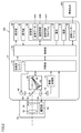
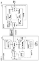
- FIG. 1 is a diagram illustrating an example of a configuration for realizing failure determination processing by the optical measurement apparatus 100.
- the optical measurement apparatus 100 includes a reference object 49, a photometry unit 64, an acceleration sensor 78, a storage unit 84, and a control unit 101 as an example of a hardware configuration.
- the control unit 101 includes a first determination unit 110, a second determination unit 112, an output unit 114, and a calibration unit 116 as an example of a functional configuration.
- the photometry unit 64 outputs measurement data 85 by measuring the measurement object.
- the measurement data 85 represents the spectral characteristics (color) of the measurement object.
- the measurement data 85 represents the light intensity for each wavelength. That is, the measurement data 85 represents a spectral spectrum of reflected light from the measurement object (hereinafter also referred to as “measurement light”).
- the storage unit 84 stores reference data 84A obtained by the photometric unit 64 measuring the reference object 49 at a predetermined timing (first timing).
- the reference data 84A is stored in advance.
- the reference object 49 is, for example, a plate of a predetermined color (for example, white).
- the first determination unit 110 determines whether or not the optical measurement apparatus 100 has a failure based on the measurement data of the reference object 49. More specifically, the first determination unit 110 acquires, from the photometry unit 64, measurement data 85 obtained by photometry of the reference object 49 at a timing (second timing) after the measurement timing of the reference data 84A.
- the reference object 49 is configured to be drivable. Preferably, the reference object 49 is driven within the field of view of the photometry unit 64 at the time of failure determination, and is driven outside the field of view of the photometry unit 64 at other times. When the reference object 49 is driven within the field of view of the photometry unit 64, the photometry unit 64 images the reference object 49. As a result, measurement data 85 is obtained.
- the first determination unit 110 determines whether or not the comparison result between the reference data 84A and the measurement data 85 satisfies a predetermined first failure condition (first condition). Details of the first failure condition will be described later.
- the second determination unit 112 determines whether or not the optical measurement apparatus 100 has a failure based on the acceleration. More specifically, the second determination unit 112 determines whether or not the acceleration included in the history information 84B satisfies a predetermined second failure condition (second condition). As an example, the second failure condition is satisfied when the acceleration included in the history information 84B exceeds a predetermined reference range. Details of the second failure condition will be described later.
- second condition a predetermined second failure condition
- the output unit 114 causes the optical measurement apparatus 100 to fail.
- Output that The output method of the diagnostic result of the optical measuring device 100 is arbitrary.
- the diagnosis result may be displayed as a message on the display unit 80 (see FIG. 2) of the optical measurement apparatus 100 or may be notified by voice.
- the optical measurement device 100 determines that the optical measurement device 100 has failed when both the first failure condition and the second failure condition are satisfied. Based on the first failure condition, it is determined whether or not the measurement data 85 is deviated from the reference data 84A. Based on the second failure condition, it is determined whether or not a large impact has been applied to the optical measurement apparatus 100 in the past. By determining the failure of the optical measurement device 100 based on both the first failure condition and the second failure condition, the presence or absence of the failure of the optical measurement device 100 is determined more accurately than in the past.
- the degree of failure that can be detected by the optical measuring apparatus 100 is arbitrary.
- the optical measurement apparatus 100 can detect a failure due to a change over time such as a product life or a failure due to a drop.
- the degree of failure due to changes over time is often smaller than the degree of failure due to falling.
- the degree of failure is resolved by a calibration process on software by the calibration unit 116. Details of the calibration process will be described later.
- the degree of failure due to falling is often greater than the degree of failure due to change over time.
- the optical measuring device 100 needs to be repaired.
- the optical measuring device 100 includes a lens unit 50 and a casing 51.
- the lens unit 50 includes a lens 52, a lens 54, and a drive unit 56.
- the lens 52 is, for example, an objective lens.
- the lens 52 forms an image of reflected light from the measurement object.
- the lens 54 is, for example, a focus lens.
- the lens 54 is a lens for adjusting the focal point.
- the drive unit 56 drives the lens 54 in the optical axis direction of the lens 54 in accordance with a control signal from the control unit 101.
- the casing 51 includes therein a half mirror 58, a light source 60, a lens 62, a photometric unit 64 (spectral unit), a lens 70, a light receiving sensor 72, an image processing unit 74, and a circuit unit 76. , An acceleration sensor 78, a display unit 80, an operation unit 82, a storage unit 84, a battery 86, a power supply 88, a communication interface 90, and a control unit 101.
- the half mirror 58 separates the measurement light that has passed through the lens 52 and the lens 54. Part of the measurement light passes through the half mirror 58 and is guided to the photometry unit 64. The remainder of the measurement light is reflected by the half mirror 58 and guided to the light receiving sensor 72.
- the light source 60 emits light of a predetermined band.
- the light source 60 is, for example, a lamp such as a xenon lamp or an LED (Light Emitting Diode).
- the light source 60 is turned on or off according to a control signal from the circuit unit 76.
- the light emitted from the light source 60 passes through the lens 62 and is guided to the photometry unit 64 by the half mirror 58.
- the photometric unit 64 includes a diffraction grating 66 (grating) and a light receiving sensor 68.
- An opening 65 is formed in the housing of the photometry unit 64.
- the measurement light that has passed through the half mirror 58 passes through the opening 65 and enters the diffraction grating 66.
- the diffraction grating 66 separates the measurement light that has passed through the opening 65 for each wavelength.
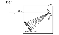
- FIG. 3 is a diagram illustrating a state in which the measurement light is dispersed for each wavelength. The split measurement light is incident on the light receiving sensor 68.
- the display unit 80 is, for example, an LCD (Liquid Crystal Display), an organic EL (Electro Luminescence) display, or other display device.
- the display unit 80 displays an image generated by the image processing unit 74 in real time in accordance with a control signal from the control unit 101. That is, the display unit 80 functions as a viewfinder.
- the display unit 80 displays the measurement result of the measurement object, the setting screen of the optical measurement apparatus 100, and the like.
- the display unit 80 includes a display and a touch panel. The display and the touch panel are overlapped with each other, and the display unit 80 receives an operation on the optical measurement apparatus 100 by a touch operation.
- the operation unit 82 receives an operation on the optical measurement apparatus 100.
- the operation unit 82 includes a power button, a measurement start button, a measurement mode selection button, a setting button (for example, a cross button, an up / down key, and the like).
- the power supply 88 supplies power to each component (for example, the acceleration sensor 78 and the control unit 101) of the optical measurement apparatus 100.
- the storage unit 84 is a storage medium such as a ROM (Read Only Memory), a RAM (Random Access Memory), or a hard disk.
- the storage unit 84 stores the above-described reference data 84A, the above-described history information 84B, and the failure determination program 84C of the optical measurement device 100.
- the failure determination program 84C may be provided as a part of an arbitrary program, not as a single program. In this case, the control process according to the present embodiment is realized in cooperation with an arbitrary program. Even such a program that does not include some modules does not depart from the spirit of the failure determination program 84C according to the present embodiment. Furthermore, some or all of the functions provided by the failure determination program 84C may be realized by dedicated hardware. Furthermore, the optical measurement apparatus 100 may be configured in a form such as a so-called cloud service in which at least one server executes part of the processing of the failure determination program 84C.
- the communication interface 90 realizes communication between the optical measuring device 100 and the communication terminal 200.
- the communication terminal 200 is, for example, a PC (Personal Computer) or a server.
- an antenna (not shown) is connected to the communication interface 90, and communication between the optical measurement device 100 and the communication terminal 200 is realized by wireless communication via the antenna.
- a wireless communication standard for example, WiFi Direct, Bluetooth (registered trademark), ZigBee, or the like is adopted.
- the communication interface 90 is a USB port, and a USB cable is connected to the USB port.
- the optical measurement device 100 and the communication terminal 200 are connected to each other via a USB cable, and communication between the optical measurement device 100 and the communication terminal 200 is realized by wired communication via the USB cable.
- the control unit 101 controls the optical measurement apparatus 100.
- the control unit 101 is configured by at least one integrated circuit, for example.
- the integrated circuit includes, for example, at least one CPU (Central Processing Unit), at least one ASIC (Application Specific Integrated Circuit), at least one FPGA (Field Programmable Gate Array), or a combination thereof.
- the optical measurement device 100 determines that the optical measurement device 100 has failed when both the first failure condition and the second failure condition are satisfied.
- FIG. 5 is a diagram showing a comparison process between the reference data 84A and the measurement data 85. As shown in FIG.
- the reference data 84A is data obtained by photometry of the reference object 49 (see FIG. 1) when the optical measuring device 100 is not broken down.
- the reference data 84A is stored in the optical measurement device 100 in advance.
- the reference data 84A represents the spectrum of the measurement light of the reference object 49. More specifically, the horizontal axis of the reference data 84A represents the wavelength of the measurement light.
- the horizontal axis of the reference data 84A may represent an identification number (arrangement position) of the light receiving elements 69 (see FIG. 3) arranged corresponding to the wavelength.
- the vertical axis of the reference data 84A represents the light intensity.
- the measurement data 85 is data obtained by photometry of the reference object 49 after the photometry timing of the reference data 84A. Similar to the reference data 84A, the measurement data 85 represents the spectral spectrum of the reflected light of the reference object 49.
- the first determination unit 110 compares the reference data 84A with the measurement data 85, and determines whether or not the comparison result satisfies the first failure condition. More specifically, the first determination unit 110 subtracts the other from at least one of the reference data 84A and the measurement data 85. At this time, the first determination unit 110 makes a difference between light intensities having the same wavelength. As a result, difference data 92 is obtained.
- the first failure condition is satisfied when the magnitude of the difference between the reference data 84A (first measurement data) and the measurement data 85 (second measurement data) exceeds a predetermined range R1 (first range). .
- the range R1 is defined by an upper limit “+ r1” and a lower limit “ ⁇ r1”.
- the range R1 may be defined by at least one of the upper limit value “+ r1” and the lower limit value “ ⁇ r1”.
- the range R1 may be set in advance or may be set by the user.
- the first failure condition is satisfied when at least one of the difference values included in the difference data 92 exceeds the range R1. In the example of FIG. 5, since at least one of the difference values included in the difference data 92 exceeds the range R1, the first failure condition is satisfied. In another aspect, the first failure condition is satisfied when the average value of the difference values included in the difference data 92 exceeds the range R1.
- the fact that the first failure condition is satisfied suggests that the light incident on the photometry unit 64 is deviated from the reference. Alternatively, this suggests that the positional relationship between the diffraction grating 66 (see FIG. 3) and the light receiving sensor 68 is shifted. Or this suggests that environment, such as temperature, changes.
- FIG. 6 is a diagram illustrating an example of the history information 84B.
- the above-described second determination unit 112 determines whether or not the acceleration included in the history information 84B satisfies the second failure condition.
- the second failure condition is satisfied when the acceleration included in the history information 84B exceeds a predetermined range R4.
- the second failure condition is satisfied when at least one of the accelerations included in the history information 84B exceeds the range R4.
- the range R4 is defined by an upper limit value “+ r4” and a lower limit value “ ⁇ r4”.
- the range R4 may be defined by at least one of an upper limit value “+ r4” and a lower limit value “ ⁇ r4”.
- the upper limit “+ r4” and the lower limit “ ⁇ r4” may be set in advance or may be arbitrarily set by the user.
- the second determination unit 112 need not refer to all the accelerations included in the history information 84B in order to determine whether or not the second failure condition is satisfied.
- the second determination unit 112 performs the measurement from the photometry timing of the reference data 84A (see FIG. 5) to the photometry timing of the measurement data 85 (see FIG. 5) from the accelerations defined in the history information 84B.
- the acceleration detected during the period is specified.
- the second determination unit 112 determines that the second failure condition is satisfied when the specified acceleration exceeds the range R4. By reducing the acceleration used for the determination of the second failure condition, the time for the determination process in the second determination unit 112 is shortened.
- the second failure condition is satisfied when the total acceleration included in the history information 84B exceeds a predetermined reference range. As a result, a failure that occurs as a result of a small impact applied to the optical measuring device 100 many times is detected.
- the second determination unit 112 does not have to sum all the accelerations included in the history information 84B.
- the second determination unit 112 identifies an acceleration that exceeds the range R3 from the accelerations defined in the history information 84B, and the total of the specified accelerations exceeds the reference range. , It is determined that the second failure condition is satisfied.
- the small impact defined by the range R3 includes vibration generated when the user brings the optical measurement device into contact with the measurement object, vibration due to hand shake, and the like.
- the range R3 is defined by an upper limit “+ r3” and a lower limit “ ⁇ r3”.
- the range R3 may be defined by at least one of an upper limit value “+ r3” and a lower limit value “ ⁇ r3”.
- the lower limit value “ ⁇ r3” of the range R3 is larger than the lower limit value “ ⁇ r4” of the range R4.
- the upper limit value “+ r3” of the range R3 is smaller than the upper limit value “+ r4” of the range R4.
- the upper limit “+ r3” and the lower limit “ ⁇ r3” may be set in advance or may be arbitrarily set by the user.
- the second determination unit 112 counts the number of accelerations exceeding the range R3 among the accelerations included in the history information 84B, and the second determination unit 112 determines the second when the count exceeds a predetermined number. Judge that the failure condition is satisfied.
- the optical measurement apparatus 100 determines that the optical measurement apparatus 100 has failed when both the first failure condition and the second failure condition are satisfied. When it is determined that the optical measuring device 100 is out of order, the output unit 114 outputs that the optical measuring device 100 is out of order. At this time, the output unit 114 changes the output content in accordance with the degree of failure of the optical measurement apparatus 100.
- the output unit 114 prompts the user to execute calibration processing when the degree of failure is small enough to eliminate the failure by the calibration processing described later.
- the output unit 114 urges the user to send the optical measurement device 100 for repair when the degree of failure is large such that the failure cannot be resolved by the calibration process.
- the degree of failure of the optical measuring device 100 is determined based on the range R1 and the range R2.
- the range R1 is defined by an upper limit value “+ r1” and a lower limit value “ ⁇ r1”.
- the range R2 is defined by an upper limit “+ r2” and a lower limit “ ⁇ r2”.
- the upper limit “+ r2” of the range R2 is larger than the upper limit “+ r1” of the range R1.
- the lower limit value “ ⁇ r2” of the range R2 is smaller than the lower limit value “ ⁇ r1” of the range R1.
- the range R1 may be defined by at least one of the upper limit value “+ r1” and the lower limit value “ ⁇ r1”.
- the range R2 may be defined by at least one of an upper limit value “+ r2” and a lower limit value “ ⁇ r2”. Range R1 and range R2 may be set in advance or may be set by the user.
- the output unit 114 When the magnitude of the difference between the reference data 84A and the measurement data 85 exceeds the range R2, the output unit 114 outputs that the optical measurement device 100 needs to be repaired. At this time, the second failure condition must also be satisfied. That the optical measuring device 100 needs to be repaired may be displayed as a message on the display unit 80 (see FIG. 2) or may be notified by voice. When the optical measuring device 100 needs to be repaired, the use of the optical measuring device 100 may be prohibited.
- the output unit 114 is output from the photometry unit 64 (see FIG. 2) when the magnitude of the difference between the reference data 84A and the measurement data 85 exceeds the range R1 and is within the range R2 outside the range R1. Outputs that calibration processing of measured data is necessary.
- the calibration process will be described later. The necessity for the calibration process may be displayed as a message on the display unit 80 or may be notified by voice.
- the optical measurement apparatus 100 executes a calibration process described later.
- the output unit 114 When the magnitude of the difference between the reference data 84A and the measurement data 85 is within the range R1, the output unit 114 outputs that the optical measurement device 100 is normal. This may be displayed as a message on the display unit 80 or may be notified by voice.
- FIG. 7 is a diagram for explaining the calibration process by the calibration unit 116.
- the calibration unit 116 calibrates the measurement data obtained from the photometry unit 64 (see FIG. 1) and performs measurement after calibration when the degree of failure that can be eliminated by the measurement data calibration process is small. Output data.
- the light source 60 (see FIG. 2) is used for the calibration process.
- the optical measuring device 100 turns on the light source 60 at a predetermined timing (third timing) and measures light from the light source 60.
- the light source 60 emits light having a wavelength ⁇ 1 in a predetermined band.
- reference data 94A (third measurement data) is obtained. Since the light source 60 emits light having the wavelength ⁇ 1, the light intensity in the reference data 94A becomes maximum at the wavelength ⁇ 1.
- the reference data 94A is stored in advance in the storage unit 84 (see FIG. 1).
- the optical measuring device 100 turns on the light source 60 at a timing (fourth timing) after the measurement timing of the reference data 94A, and measures the light from the light source 60. Thereby, measurement data 94B (fourth measurement data) is obtained.
- measurement data 94B (fourth measurement data) is obtained.
- the position of the optical system is deviated, even if the light source 60 emits light having the wavelength ⁇ 1, the light intensity in the measurement data 94B becomes maximum at the wavelength ⁇ 2. That is, the measurement data 94B is shifted by the difference between the wavelength ⁇ 1 and the wavelength ⁇ 2.
- the calibration unit 116 calibrates the measurement data output from the photometry unit 64 according to the difference between the reference data 94A and the measurement data 94B. More specifically, the calibration unit 116 shifts the wavelength of the measurement data output from the photometry unit 64 by the difference between the wavelengths ⁇ 1 and ⁇ 2. Thereby, the wavelength shift is eliminated.
- the calibration unit 116 may perform calibration processing using the above-described reference data 84A (see FIG. 5) and measurement data 85 (see FIG. 5) instead of the reference data 94A and the measurement data 94B.
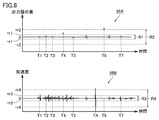
- FIG. 8 is a diagram showing a temporal change in the magnitude of the difference between the reference data 84A (see FIG. 5) and the measurement data 85 (see FIG. 5), and a temporal change in the acceleration of the optical measurement apparatus 100. is there.
- FIG. 8 shows a graph 96A and a graph 96B.
- the horizontal axis of the graph 96A represents time.
- the vertical axis of the graph 96A represents the magnitude of the difference between the reference data 84A and the measurement data 85.
- the magnitude of the difference corresponds to, for example, a representative value of the difference value included in the above-described difference data 92 (see FIG. 5).
- the maximum absolute value of each difference value included in the difference data 92 is selected as a representative value.
- the graph 96B corresponds to the above-described history information 84B (see FIG. 6).
- the horizontal axis of the graph 96B represents time.
- the vertical axis of the graph 96 ⁇ / b> B represents the acceleration of the optical measurement apparatus 100.
- the failure determination process is started at an arbitrary timing.
- the failure determination process is started when the optical measurement apparatus 100 is turned on.
- the failure determination process is started when the optical measurement apparatus 100 is turned off.
- the failure determination process is periodically executed.
- the optical measurement apparatus 100 starts a failure determination process. Since the representative value of the difference data 92 at time T1 is within the range R1, the first failure condition described above is not satisfied. Therefore, the optical measuring device 100 notifies that it is normal.
- the optical measurement apparatus 100 starts a failure determination process. Since the representative value of the difference data 92 at time T2 is within the range R1, the first failure condition described above is not satisfied. Therefore, the optical measuring device 100 notifies that it is normal.
- the optical measurement device 100 starts a failure determination process. Since the representative value of the difference data 92 at time T3 is within the range R1, the first failure condition described above is not satisfied. Therefore, the optical measuring device 100 notifies that it is normal.
- the optical measurement device 100 starts a failure determination process. Since the representative value of the difference data 92 at time T4 exceeds the range R1, the first failure condition described above is satisfied. At this time, since the representative value of the difference data 92 is within the range R2, the optical measurement apparatus 100 determines that the degree of failure is small. As a result, the optical measurement apparatus 100 executes the above-described calibration process.
- the optical measurement device 100 starts a failure determination process. Since the representative value of the difference data 92 at the time T5 is within the range R1, the measurement data is normally calibrated by the calibration process at the time T4. The optical measuring device 100 notifies that it is normal.
- the optical measurement apparatus 100 starts a failure determination process. Since the representative value of the difference data 92 at time T6 exceeds the range R1, the first failure condition described above is satisfied. Since the representative value of the difference data 92 exceeds the range R2 outside the range R1, the optical measurement apparatus 100 refers to the acceleration history information 84B and determines whether or not the second failure condition is satisfied. At this time, the optical measuring apparatus 100 preferably refers to the acceleration detected from time T6, which is the timing of the current failure determination process, to time T5, which is the timing of the previous failure determination process. The referred acceleration exceeds the range R4 at time TA. Therefore, the optical measurement device 100 determines that the second failure condition is satisfied. Since both the first failure condition and the second failure condition are satisfied, the optical measurement apparatus 100 notifies that repair is necessary. The user requests the manufacturer or service department to repair the optical measuring device 100.
- the optical measuring device 100 starts a failure determination process. Since the optical measurement device 100 has been repaired, the representative value of the difference data 92 at time T7 is within the range R1. The optical measuring device 100 notifies that it is normal.
- FIG. 9 is a flowchart showing failure determination processing of the optical measurement apparatus 100.
- the processing in FIG. 9 is realized by the control unit 101 (see FIG. 1) of the optical measurement apparatus 100 executing a program. In other aspects, some or all of the processing may be performed by circuit elements or other hardware.
- step S100 the control unit 101 determines whether or not the optical measurement apparatus 100 is turned on.
- control unit 101 determines that optical measurement apparatus 100 is powered on (YES in step S100)
- control unit 101 switches control to step S110.
- step S100 NO the control part 101 switches control to step S102.
- step S102 the control unit 101 sends a control signal to the acceleration sensor 78 to detect the acceleration of the optical measuring device 100.
- step S104 the control unit 101 associates the acceleration detected in step S102 with the detection time, and adds these pieces of information to the history information 84B (see FIG. 6).
- the acceleration detection time is specified by, for example, a timer function provided in advance in the control unit 101.
- step S110 the control unit 101 drives the reference object 49 (see FIG. 1) within the field of view of the photometry unit 64 (see FIG. 1).
- the drive mechanism of the reference object 49 is arbitrary.
- the reference object 49 is driven by a plunger.
- step S112 the control unit 101 performs photometry on the reference object 49. Thereby, measurement data 85 (see FIG. 5) is obtained.
- step S120 the control unit 101 determines, as the first determination unit 110 (see FIG. 1), whether or not the first failure condition described above is satisfied.
- control unit 101 determines that the first failure condition is satisfied (YES in step S120)
- control unit 101 switches control to step S130. Otherwise (NO in step S120), control unit 101 switches control to step S132.
- step S130 the control unit 101 determines whether the second failure condition described above is satisfied as the second determination unit 112 (see FIG. 1). When control unit 101 determines that the second failure condition is satisfied (YES in step S130), control unit 101 switches control to step S140. If not (NO in step S130), control unit 101 switches control to step S132.
- step S132 the control unit 101 notifies the output unit 114 (see FIG. 1) that the optical measurement device 100 is normal.
- step S140 the control unit 101 determines whether or not the failure of the optical measurement apparatus 100 can be solved by the calibration process described above.
- the control unit 101 determines that the failure of the optical measurement apparatus 100 can be resolved by the above-described calibration process (YES in step S140)
- the control unit 101 switches the control to step S144. If not (NO in step S140), control unit 101 switches control to step S142.
- step S142 the control unit 101 notifies the output unit 114 that the optical measuring device 100 needs to be repaired.
- step S144 the control unit 101 notifies the output unit 114 that the measurement data needs to be calibrated.
- step S150 the control unit 101 determines whether or not permission to execute the calibration process of the measurement data has been received.
- the control unit 101 displays a selection screen including a permission button and a rejection button on the display unit 80.
- the control unit 101 determines that the execution of the calibration process is permitted when the permission button is selected.
- the control unit 101 determines that the execution of the calibration process has been rejected when the reject button is selected.
- control unit 101 switches control to step S152. If not (NO in step S150), control unit 101 ends the failure determination process.
- step S152 the control unit 101 performs the above-described calibration process as the calibration unit 116.
- optical measurement apparatus 100 determines that optical measurement apparatus 100 has failed when the first failure condition and the second failure condition are satisfied. Based on the first failure condition, it is determined whether or not the measurement data 85 (see FIG. 5) is deviated from the reference data 84A (see FIG. 5). Based on the second failure condition, it is determined whether or not a large impact has been applied to the optical measurement apparatus 100 in the past.
- the optical measuring device 100 can determine whether there is a failure more accurately than in the past by determining a failure based on both the first failure condition and the second failure condition.
- the failure determination of the optical measurement device 100 is performed by the optical measurement device 100.
- the failure determination of the optical measurement device 100 is performed by the communication terminal 200 which is a failure determination device. Since other points are the same as those of the first embodiment, the other points will not be described below.
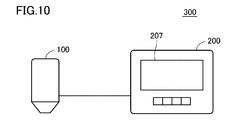
- FIG. 10 is a diagram illustrating an example of a system configuration of the failure determination system 300.
- FIG. 11 is a diagram illustrating an example of a configuration for realizing the failure determination processing by the failure determination system 300.
- the failure determination system 300 includes an optical measurement device 100 and a communication terminal 200.
- the optical measuring device 100 and the communication terminal 200 are connected to each other via a network.
- Communication between the optical measurement apparatus 100 and the communication terminal 200 may be realized by wireless communication or may be realized by wired communication.
- the optical measurement apparatus 100 includes a reference object 49, a photometry unit 64, an acceleration sensor 78, a storage unit 84, a communication unit 105, a control unit 101, and the like as an example of a hardware configuration.
- the control unit 101 includes a calibration unit 116 as an example of a functional configuration.
- the communication terminal 200 includes a control unit 201 and a communication unit 205 as an example of a hardware configuration.
- the control unit 201 is configured by at least one integrated circuit, for example.
- the integrated circuit includes, for example, at least one CPU, at least one ASIC, at least one FPGA, or a combination thereof.
- the control unit 201 includes a first determination unit 210, a second determination unit 212, and an output unit 214 as an example of a functional configuration.
- the user When determining the failure of the optical measuring device 100, the user connects the optical measuring device 100 to the communication terminal 200. As a result, the communication terminal 200 establishes communication with the optical measurement device 100. Thereafter, when the user inputs an instruction to execute the failure determination process to the communication terminal 200, the communication unit 205 transmits a request for acquiring information used for the failure determination process to the optical measurement apparatus 100.
- the communication unit 205 is, for example, a communication interface (not shown).
- the communication unit 105 (first communication unit) of the optical measurement device 100 performs the above-described reference data 84A, the above-described history information 84B, and the above-described measurement. Data 85 is transmitted to communication terminal 200.
- the communication unit 105 is, for example, the above-described communication interface 90 (see FIG. 2).
- the communication unit 205 (second communication unit) of the communication terminal 200 receives the reference data 84A, the history information 84B, and the measurement data 85 from the optical measurement device 100.
- the communication unit 205 outputs the reference data 84A and the measurement data 85 to the first determination unit 210, and outputs the history information 84B to the second determination unit 212.
- 1st judgment part 210 performs the same processing as the above-mentioned 1st judgment part 110 (refer to Drawing 1). That is, the first determination unit 210 determines whether the comparison result between the reference data 84A and the measurement data 85 satisfies the first failure condition described above.
- the second determination unit 212 executes the same process as the above-described second determination unit 112 (see FIG. 1). That is, the second determination unit 212 determines whether or not the magnitude of acceleration included in the history information 84B satisfies the second failure condition described above.
- the output unit 214 performs the same processing as the output unit 114 (see FIG. 1) described above. That is, when the first determination unit 210 determines that the first failure condition is satisfied and the second determination unit 212 determines that the second failure condition is satisfied, the output unit 214 determines that the optical measurement apparatus 100 is Outputs that there is a failure.
- the communication unit 205 transmits a notification indicating that to the optical measurement device 100. That is, the communication unit 205 determines that the difference between the reference data 84A and the measurement data 85 exceeds the range R1 (see FIG. 5) and is within the range R2 (see FIG. 5). A notification indicating that calibration processing of the output measurement data is necessary is transmitted to the optical measurement apparatus 100.
- the calibration unit 116 executes the calibration process described above.
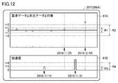
- FIG. 12 is a diagram showing a use history 208A of the optical measuring device 100.
- the usage history 208A is displayed on the display unit 207 of the communication terminal 200, for example.
- the usage history 208A includes a graph 97A and a graph 97B.
- the horizontal axis of the graph 97A represents time.
- the vertical axis of the graph 97A indicates the magnitude of the difference between the reference data 84A and the measurement data 85. The magnitude of the difference is expressed in the order of time series.
- the horizontal axis of the graph 97B represents time.
- the vertical axis of the graph 97B represents the acceleration of the optical measurement apparatus 100. The acceleration is expressed in the order of time series.
- the repairer can easily identify the cause of the failure of the optical measuring device 100 by checking the usage history 208A. As an example, the repairer can specify that the measurement data 85 is deviated from the reference data 84A by checking the graph 97A. Further, the repairer can identify that a large impact has been given to the optical measuring device 100 in the past by checking the graph 97B. As a result, the repair person can estimate that the optical system of the optical measuring device 100 is shifted. As a result, the repair period and the number of repair steps of the optical measuring device 100 are reduced.
- FIG. 13 is a diagram illustrating a usage history 208B of the optical measurement apparatus 100.
- the usage history 208B includes a graph 98A and a graph 98B.
- the horizontal axis of the graph 98A represents time.
- the vertical axis of the graph 98A indicates the magnitude of the difference between the reference data 84A and the measurement data 85. The magnitude of the difference is expressed in the order of time series.
- the horizontal axis of the graph 98B represents time.
- the vertical axis of the graph 98B represents the acceleration of the optical measurement apparatus 100. The acceleration is expressed in the order of time series.
- the repair person can specify that the measurement data 85 is deviated from the reference data 84A by checking the graph 98A. Further, the repairer can identify that the small impact has been given to the optical measuring device 100 many times in the past by checking the graph 98B.
- the optical measurement device stores a photometry unit, a sensor for detecting the magnitude of vibration of the optical measurement device, and first measurement data obtained from the photometry unit by measuring a reference object at a first timing.
- a storage unit for storing the magnitude of vibration detected by the sensor as history information, and a second obtained from the photometry unit by measuring the reference object at a second timing after the first timing.
- a first determination unit for determining whether a comparison result between the measurement data and the first measurement data satisfies a predetermined first condition; and the magnitude of the vibration included in the history information is determined in advance.
- a second determination unit for determining whether or not a predetermined second condition is satisfied; the first determination unit determines that the first condition is satisfied; and the second determination unit determines whether the second condition is satisfied. If it is determined that has been met, and an output unit for outputting the above optical measuring device has failed.
- the first condition is satisfied when the magnitude of the difference between the first measurement data and the second measurement data exceeds a predetermined first range.
- the output unit outputs from the photometry unit when the magnitude of the difference exceeds the first range and falls within a predetermined second range outside the first range.
- the fact that the measurement data needs to be calibrated is output, and if the magnitude of the difference exceeds the second range, it is output that the optical measuring device needs to be repaired.
- the optical measurement device further includes a light source that emits light.
- the storage unit further stores third measurement data obtained from the photometry unit by measuring the light at a third timing.
- the optical measurement device measures the light at a fourth timing after the third timing when the magnitude of the difference exceeds the first range and is within the second range.
- a calibration unit is further provided for calibrating the measurement data output from the photometry unit according to the magnitude of the difference between the fourth measurement data obtained from the photometry unit and the third measurement data.
- the second condition is satisfied when the magnitude of the vibration included in the history information exceeds a predetermined reference range.
- the second determination unit specifies the magnitude of vibration detected between the first timing and the second timing from the magnitudes of vibration defined in the history information, When the magnitude of the vibration exceeds the reference range, it is determined that the second condition is satisfied.
- the second condition is satisfied when the sum of the magnitudes of the vibrations included in the history information exceeds a predetermined reference range.
- the failure determination system includes an optical measurement device and a communication terminal capable of communicating with the optical measurement device.
- the optical measurement device stores a photometry unit, a sensor for detecting the magnitude of vibration of the optical measurement device, and first measurement data obtained from the photometry unit by measuring a reference object at a first timing.
- a storage unit for storing the magnitude of vibration detected by the sensor as history information, and a second obtained from the photometry unit by measuring the reference object at a second timing after the first timing.
- a first communication unit configured to transmit the measurement data, the first measurement data, and the history information to the communication terminal;
- the communication terminal has a second communication unit for receiving the first measurement data, the second measurement data, and the history information, and a comparison result between the first measurement data and the second measurement data is predetermined.
- a first determination unit for determining whether or not the first condition set is satisfied, and for determining whether or not the magnitude of the vibration included in the history information satisfies a predetermined second condition
- the optical measurement device fails.
- an output unit for outputting information indicating that the operation is being performed.
- the first condition is satisfied when the magnitude of the difference between the first measurement data and the second measurement data exceeds a predetermined first range.
- the second communication unit is a measurement output from the photometry unit when the magnitude of the difference exceeds the first range and is within a predetermined second range outside the first range. A notification indicating that the data calibration process is necessary is transmitted to the optical measuring device.
Landscapes
- Physics & Mathematics (AREA)
- Spectroscopy & Molecular Physics (AREA)
- General Physics & Mathematics (AREA)
- Engineering & Computer Science (AREA)
- Human Computer Interaction (AREA)
- Photometry And Measurement Of Optical Pulse Characteristics (AREA)
- Spectrometry And Color Measurement (AREA)
Abstract
故障の有無を従来よりも正確に判断できる光学測定装置を提供する。光学測定装置(100)は、測光部(64)と、光学測定装置(100)の加速度を検知する加速度センサー(78)と、第1タイミングにおいて基準物体(49)を測光して測光部(64)から得られた基準データ(84A)を格納し、加速度センサー(78)によって検知された加速度を履歴情報(84B)として格納する記憶部(84)と、第1タイミングよりも後の第2タイミングにおいて基準物体(49)を測光して測光部(64)から得られる測定データ(85)と、基準データ(84A)との比較結果が第1故障条件を満たしたか否かを判断する第1判断部(110)と、履歴情報(84B)に含まれる加速度が第2故障条件を満たしたか否かを判断する第2判断部(112)と、第1故障条件および第2故障条件が満たされたと判断された場合に、光学測定装置(100)が故障していることを出力する出力部(114)とを備える。
Description
本開示は、光学測定装置に関し、特に、光学測定装置の故障の有無を判断するための技術に関する。
測定対象物の色彩を測定することが可能な光学測定装置が普及している。光学測定装置は、製品寿命や落下などの様々な要因で故障する。光学測定装置が故障すると、測定精度が低下する。このことを防止するために、光学測定装置の故障を検知するための技術が開発されている。
故障の有無を判断するための技術に関し、特開平10-307062号公報(特許文献1)は、故障の内容を測定者に報知することが可能な分光測定装置を開示している。特開平10-153545号公報(特許文献2)は、異常を報知することが可能な分光分析機を開示している。
特開平10-307062号公報に開示される分光測定装置は、測定対象物を測定して得られる信号強度が所定値未満に低下した場合に、分光測定装置が故障していると判断する。しかしながら、信号強度が所定値未満に低下した場合であっても、分光測定装置は故障しているとは限らない。
特開平10-153545号公報に開示される分光分析機は、振動センサーを有する。当該分光分析機は、振動センサーからの出力値が所定値を超えた場合に、分光分析機が故障したと判断する。しかしながら、振動センサーからの出力値が所定値を超えた場合であっても、分光分析機は故障しているとは限らない。
したがって、故障の有無を従来よりも正確に判断することが可能な光学測定装置が望まれている。
本開示は上述のような問題点を解決するためになされたものであって、ある局面における目的は、故障の有無を従来よりも正確に判断することが可能な光学測定装置を提供することである。他の局面における目的は、故障の有無を従来よりも正確に判断することが可能な故障判断システムを提供することである。さらに他の局面における目的は、故障の有無を従来よりも正確に判断することが可能な故障判断方法を提供することである。さらに他の局面における目的は、故障の有無を従来よりも正確に判断することが可能な故障判断プログラムを提供することである。
光学測定装置は、測光部と、上記光学測定装置の振動の大きさを検知するためのセンサーと、第1タイミングにおいて基準物体を測光して上記測光部から得られた第1測定データを格納し、上記センサーによって検知された振動の大きさを履歴情報として格納するための記憶部と、上記第1タイミングよりも後の第2タイミングにおいて上記基準物体を測光して上記測光部から得られる第2測定データと、上記第1測定データとの比較結果が予め定められた第1条件を満たしたか否かを判断するための第1判断部と、上記履歴情報に含まれる上記振動の大きさが予め定められた第2条件を満たしたか否かを判断するための第2判断部と、上記第1判断部によって上記第1条件が満たされたと判断され、かつ上記第2判断部によって上記第2条件が満たされたと判断された場合に、上記光学測定装置が故障していることを出力するための出力部とを備える。
他の局面に従うと、故障判断システムは、光学測定装置と、上記光学測定装置と通信可能な通信端末とを備える。光学測定装置は、測光部と、上記光学測定装置の振動の大きさを検知するためのセンサーと、第1タイミングにおいて基準物体を測光して上記測光部から得られた第1測定データを格納し、上記センサーによって検知された振動の大きさを履歴情報として格納するための記憶部と、上記第1タイミングよりも後の第2タイミングにおいて上記基準物体を測光して上記測光部から得られる第2測定データと、上記第1測定データと、上記履歴情報とを上記通信端末に送信するための第1通信部とを含む。上記通信端末は、上記第1測定データと上記第2測定データと上記履歴情報とを受信するための第2通信部と、上記第1測定データと上記第2測定データとの比較結果が予め定められた第1条件を満たしたか否かを判断するための第1判断部と、上記履歴情報に含まれる上記振動の大きさが予め定められた第2条件を満たしたか否かを判断するための第2判断部と、上記第1判断部によって上記第1条件が満たされたと判断され、かつ上記第2判断部によって上記第2条件が満たされたと判断された場合に、上記光学測定装置が故障していることを出力するための出力部とを含む。
さらに他の局面に従うと、光学測定装置の故障判断方法が提供される。上記光学測定装置は、測光部と、上記光学測定装置の振動の大きさを検知するためのセンサーと、第1タイミングにおいて基準物体を測光して上記測光部から得られた第1測定データを格納し、上記センサーによって検知された振動の大きさを履歴情報として格納するための記憶部とを備える。上記故障判断方法は、上記第1タイミングよりも後の第2タイミングにおいて上記基準物体を測光して上記測光部から得られる第2測定データと、上記第1測定データとの比較結果が予め定められた第1条件を満たしたか否かを判断するステップと、上記履歴情報に含まれる上記振動の大きさが予め定められた第2条件を満たしたか否かを判断するステップと、上記第1条件が満たされ、かつ上記第2条件が満たされた場合に、上記光学測定装置が故障していることを出力するステップとを備える。
さらに他の局面に従うと、光学測定装置の故障判断プログラムが提供される。上記光学測定装置は、測光部と、上記光学測定装置の振動の大きさを検知するためのセンサーと、第1タイミングにおいて基準物体を測光して上記測光部から得られた第1測定データを格納し、上記センサーによって検知された振動の大きさを履歴情報として格納するための記憶部とを備える。上記故障判断プログラムは、上記光学測定装置に、上記第1タイミングよりも後の第2タイミングにおいて上記基準物体を測光して上記測光部から得られる第2測定データと、上記第1測定データとの比較結果が予め定められた第1条件を満たしたか否かを判断するステップと、上記履歴情報に含まれる上記振動の大きさが予め定められた第2条件を満たしたか否かを判断するステップと、上記第1条件が満たされ、かつ上記第2条件が満たされた場合に、上記光学測定装置が故障していることを出力するステップとを実行させる。
ある局面において、光学測定装置の故障の有無を従来よりも正確に判断することができる。
本発明の上記および他の目的、特徴、局面および利点は、添付の図面と関連して理解される本発明に関する次の詳細な説明から明らかとなるであろう。
以下、図面を参照しつつ、本発明に従う各実施の形態について説明する。以下の説明では、同一の部品および構成要素には同一の符号を付してある。それらの名称および機能も同じである。したがって、これらについての詳細な説明を繰り返さない。なお、以下で説明される各実施の形態および各変形例は、適宜選択的に組み合わされてもよい。
<第1の実施の形態>
[光学測定装置100の概要]
図1を参照して、本実施の形態に従う光学測定装置100について説明する。図1は、光学測定装置100による故障判断処理を実現するための構成の一例を示す図である。
[光学測定装置100の概要]
図1を参照して、本実施の形態に従う光学測定装置100について説明する。図1は、光学測定装置100による故障判断処理を実現するための構成の一例を示す図である。
図1に示されるように、光学測定装置100は、ハードウェア構成の一例として、基準物体49と、測光部64と、加速度センサー78と、記憶部84と、制御部101とを含む。制御部101は、機能構成の一例として、第1判断部110と、第2判断部112と、出力部114と、校正部116とを含む。
測光部64は、測定対象物を測光することで測定データ85を出力する。測定データ85は、測定対象物の分光特性(色彩)を表わす。一例として、測定データ85は、波長ごとの光強度を表わす。すなわち、測定データ85は、測定対象物からの反射光(以下、「測定光」ともいう。)の分光スペクトルを表わす。
加速度センサー78(センサー)は、光学測定装置100の振動の大きさを検知する。振動の大きさは、たとえば、光学測定装置100の加速度で表わされる。以下では、光学測定装置100の振動を表わす指標として加速度を用いて説明を行なうが、振動の大きさは、加速度以外の指標で表わされてもよい。たとえば、振動の大きさは、光学測定装置100の速度で表わされてもよい。この場合、加速度センサー78の代わりに速度センサー(図示しない)が設けられる。
記憶部84は、所定のタイミング(第1タイミング)において測光部64が基準物体49を測光して得られた基準データ84Aを格納している。基準データ84Aは、予め格納されている。基準物体49は、たとえば、所定色(たとえば、白色)の板である。
また、記憶部84は、加速度センサー78によって検知された加速度を履歴情報84Bとして格納する。一例として、光学測定装置100の加速度は一定時間ごとに検知され、検知された加速度は、検知時刻に対応付けられた上で履歴情報84Bに書き込まれる。履歴情報84Bには、検知された全ての加速度が書き込まれてもよいし、所定値を超えた加速度だけが書き込まれてもよい。
第1判断部110は、基準物体49の測定データに基づいて光学測定装置100の故障の有無を判断する。より具体的には、第1判断部110は、基準データ84Aの測定タイミングよりも後のタイミング(第2タイミング)において基準物体49を測光して得られる測定データ85を測光部64から取得する。基準物体49は、駆動可能に構成されている。好ましくは、基準物体49は、故障判断時において測光部64の視野内に駆動され、それ以外の時には測光部64の視野外に駆動される。基準物体49が測光部64の視野内に駆動されると、測光部64は、基準物体49を撮像する。その結果、測定データ85が得られる。第1判断部110は、基準データ84Aと測定データ85との比較結果が予め定められた第1故障条件(第1条件)を満たしたか否かを判断する。第1故障条件の詳細については後述する。
第2判断部112は、加速度に基づいて光学測定装置100の故障の有無を判断する。より具体的には、第2判断部112は、履歴情報84Bに含まれる加速度が予め定められた第2故障条件(第2条件)を満たしたか否かを判断する。一例として、第2故障条件は、履歴情報84Bに含まれる加速度が予め定められた基準範囲を超えている場合に満たされる。第2故障条件の詳細については後述する。
出力部114は、第1判断部110によって第1故障条件が満たされたと判断され、かつ第2判断部112によって第2故障条件が満たされたと判断された場合に、光学測定装置100が故障していることを出力する。光学測定装置100の診断結果の出力方法は、任意である。診断結果は、光学測定装置100の表示部80(図2参照)にメッセージで表示されてもよいし、音声で報知されてもよい。
以上のように、光学測定装置100は、第1故障条件および第2故障条件の両方が満たされたときに、光学測定装置100が故障していると判断する。第1故障条件により、測定データ85が基準データ84Aからずれているか否かが判断される。第2故障条件により、過去に光学測定装置100に対して大きな衝撃が与えられたか否かが判断される。第1故障条件および第2故障条件の両方で光学測定装置100の故障が判断されることで、光学測定装置100の故障の有無が従来よりも正確に判断される。
なお、光学測定装置100が検知可能な故障の程度は任意である。一例として、光学測定装置100は、製品寿命などの継時変化による故障や、落下による故障を検知することができる。継時変化による故障の程度は、落下による故障の程度よりも小さいことが多い。故障の程度が小さい場合には、校正部116によるソフトウェア上の校正処理により故障が解消される。当該校正処理の詳細については後述する。一方で、落下による故障の程度は、継時変化による故障の程度よりも大きいことが多い。故障の程度が大きい場合には、光学測定装置100の修理が必要となる。
[光学測定装置100の内部構成]
図2~図4を参照して、光学測定装置100の内部構成について説明する。図2は、光学測定装置100の内部構成の一例を示す図である。
図2~図4を参照して、光学測定装置100の内部構成について説明する。図2は、光学測定装置100の内部構成の一例を示す図である。
図2に示されるように、光学測定装置100は、レンズ部50と、筐体51とで構成されている。レンズ部50は、レンズ52と、レンズ54と、駆動部56とで構成されている。
レンズ52は、たとえば対物レンズである。レンズ52は、測定対象物からの反射光を結像する。レンズ54は、たとえばフォーカスレンズである。レンズ54は、焦点を調整するためのレンズである。駆動部56は、制御部101からの制御信号に従って、レンズ54の光軸方向にレンズ54を駆動する。
筐体51は、その内部に、ハーフミラー58と、光源60と、レンズ62と、測光部64(分光ユニット)と、レンズ70と、受光センサー72と、画像処理部74と、回路部76と、加速度センサー78と、表示部80と、操作部82と、記憶部84と、電池86と、電源88と、通信インターフェイス90と、制御部101とを含む。
ハーフミラー58は、レンズ52およびレンズ54を通過した測定光を分光する。測定光の一部は、ハーフミラー58を通過し、測光部64に導かれる。測定光の残りは、ハーフミラー58で反射され、受光センサー72に導かれる。
光源60は、所定帯域の光を放射する。光源60は、たとえば、キセノンランプなどのランプ、またはLED(Light Emitting Diode)である。光源60は、回路部76からの制御信号に従って点灯または消灯する。光源60から照射された光は、レンズ62を通過し、ハーフミラー58によって測光部64に導かれる。
測光部64は、回折格子66(グレーティング)と、受光センサー68とで構成されている。測光部64の筐体には、開口部65が形成されている。ハーフミラー58を通過した測定光は、開口部65を通過して回折格子66に入射する。回折格子66は、開口部65を通過した測定光を波長ごとに分光する。図3は、測定光が波長ごとに分光されている様子を示す図である。分光された測定光は、受光センサー68に入射する。
受光センサー68は、たとえばラインセンサーである。受光センサー68は、直線状に並べられた複数の受光素子69で構成されている。受光素子69の各々は、対応する波長の測定光を受け、当該測定光を光電変換により電気信号に変換し、当該電気信号を回路部76に出力する。回路部76は、受光素子69の各々から出力された電気信号をデジタル信号(電圧値)に変換し、当該デジタル信号に基づいて測定光の光強度を波長ごとに算出する。その結果、分光スペクトルが得られる。分光スペクトルは、制御部101に出力される。好ましくは、分光スペクトルは、光源60の変動や各センサーの感度のばらつきがキャンセルされた上で制御部101に出力される。
受光センサー72は、たとえば、CCD(Charge Coupled Device)やC-MOS(Complementary Metal Oxide Semiconductor)などの2次元のイメージセンサーである。受光センサー72は、レンズ70を通過した測定光を受けて測定対象物を表わす画像を生成する。より具体的には、受光センサー72は、光電変換により測定光を電気信号に変換し、当該電気信号を画像処理部74に出力する。画像処理部74は、受光センサー72から得られた電気信号をデジタル信号(電圧値)に変換し、当該デジタル信号に基づいて、測定対象物を表わす画像を生成する。生成される画像は、モノクロ画像であってもよいし、カラー画像であってもよい。カラー画像は、たとえば、測定対象物の赤色成分を表わすR画像と、測定対象物の緑色成分を表わすG画像と、測定対象物の青色成分を表わすB画像とで構成されている。
加速度センサー78は、光学測定装置100の加速度を検知する。加速度センサー78によって検知された加速度は、検知時刻に対応付けられた上で履歴情報84Bに書き込まれる。検知された加速度は、全て履歴情報84Bに書き込まれてもよいし、予め定められた値を超えた加速度だけが履歴情報84Bに書き込まれてもよい。加速度センサー78は、電池86および電源88のいずれか一方から電力の供給を受ける。図4は、光学測定装置100の電源88の状態と、加速度センサー78に対する電力の供給元との関係を示す図である。図4に示されるように、電源88がオフの状態にあるときには、加速度センサー78は、電池86から電力の供給を受ける。一方で、電源88がオンの状態にあるときには、加速度センサー78は、電源88から電力の供給を受ける。
表示部80は、たとえば、LCD(Liquid Crystal Display)、有機EL(Electro Luminescence)ディスプレイ、またはその他の表示機器である。表示部80は、制御部101からの制御信号に従って、画像処理部74によって生成される画像をリアルタイムに表示する。すなわち、表示部80は、ファインダーとして機能する。また、表示部80は、測定対象物の測定結果や光学測定装置100の設定画面などを表示する。好ましくは、表示部80は、ディスプレイとタッチパネルとで構成されている。ディスプレイおよびタッチパネルは互いに重ねられており、表示部80は、光学測定装置100に対する操作をタッチ操作で受け付ける。
操作部82は、光学測定装置100に対する操作を受け付ける。一例として、操作部82は、電源ボタン、測定開始ボタン、測定モードの選択ボタン、設定ボタン(たとえば、十字ボタン、アップダウンキーなど)などで構成されている。電源ボタンが押下されたことに基づいて、電源88は、光学測定装置100の各構成(たとえば、加速度センサー78や制御部101など)に電力を供給する。
記憶部84は、たとえば、ROM(Read Only Memory)、RAM(Random Access Memory)、ハードディスクなどの記憶媒体である。一例として、記憶部84は、上述の基準データ84Aと、上述の履歴情報84Bと、光学測定装置100の故障判断プログラム84Cとを格納する。
故障判断プログラム84Cは、単体のプログラムとしてではなく、任意のプログラムの一部に組み込まれて提供されてもよい。この場合、本実施の形態に従う制御処理は、任意のプログラムと協働して実現される。このような一部のモジュールを含まないプログラムであっても、本実施の形態に従う故障判断プログラム84Cの趣旨を逸脱するものではない。さらに、故障判断プログラム84Cによって提供される機能の一部または全部は、専用のハードウェアによって実現されてもよい。さらに、少なくとも1つのサーバーが故障判断プログラム84Cの処理の一部を実行する所謂クラウドサービスのような形態で光学測定装置100が構成されてもよい。
通信インターフェイス90は、光学測定装置100と通信端末200との間の通信を実現する。通信端末200は、たとえば、PC(Personal Computer)やサーバーなどである。ある局面において、通信インターフェイス90にはアンテナ(図示しない)が接続され、光学測定装置100と通信端末200との間の通信は、当該アンテナ介した無線通信によって実現される。無線通信の規格としては、たとえば、Wifiダイレクト、Bluetooth(登録商標)、ZigBeeなどが採用される。他の局面において、通信インターフェイス90はUSBポートであり、USBポートには、USBケーブルが接続される。光学測定装置100と通信端末200とはUSBケーブルを介して互いに接続され、光学測定装置100と通信端末200との間の通信は、USBケーブルを介した有線通信によって実現される。
制御部101は、光学測定装置100を制御する。制御部101は、たとえば、少なくとも1つの集積回路によって構成される。集積回路は、たとえば、少なくとも1つのCPU(Central Processing Unit)、少なくとも1つのASIC(Application Specific Integrated Circuit)、少なくとも1つのFPGA(Field Programmable Gate Array)、またはそれらの組み合わせなどによって構成される。
[第1故障条件]
上述したように、光学測定装置100は、第1故障条件および第2故障条件の両方が満たされた場合に、光学測定装置100が故障したと判断する。
上述したように、光学測定装置100は、第1故障条件および第2故障条件の両方が満たされた場合に、光学測定装置100が故障したと判断する。
以下では、図5を参照して、第1故障条件について説明する。図5は、基準データ84Aと測定データ85との比較処理を示す図である。
基準データ84Aは、光学測定装置100が故障していないときに、基準物体49(図1参照)を測光して得られたデータである。基準データ84Aは、光学測定装置100に予め格納されている。基準データ84Aは、基準物体49の測定光の分光スペクトルを表わす。より具体的には、基準データ84Aの横軸は、測定光の波長を表わす。なお、基準データ84Aの横軸は、波長に対応して配列された受光素子69(図3参照)の識別番号(配置位置)を表わしてもよい。基準データ84Aの縦軸は、光強度を表わす。
測定データ85は、基準データ84Aの測光タイミングよりも後に、基準物体49を測光して得られたデータである。基準データ84Aと同様に、測定データ85は、基準物体49の反射光の分光スペクトルを表わす。
上述の第1判断部110(図1参照)は、基準データ84Aと測定データ85とを比較し、当該比較結果が第1故障条件を満たしたか否かを判断する。より具体的には、第1判断部110は、基準データ84Aおよび測定データ85の少なくとも一方から他方を差分する。このとき、第1判断部110は、波長が等しい光強度同士を差分する。その結果、差分データ92が得られる。第1故障条件は、基準データ84A(第1測定データ)および測定データ85(第2測定データ)の差異の大きさが予め定められた範囲R1(第1範囲)を超えている場合に満たされる。
範囲R1は、上限値「+r1」および下限値「-r1」で規定されている。なお、範囲R1は、上限値「+r1」および下限値「-r1」の少なくとも一方で規定されてもよい。範囲R1は、予め設定されていてもよいし、ユーザーによって設定されてもよい。
ある局面において、差分データ92に含まれる差分値の少なくとも1つが範囲R1を超えている場合に、第1故障条件が満たされる。図5の例では、差分データ92に含まれる差分値の少なくとも1つが範囲R1を超えているため、第1故障条件が満たされる。他の局面において、差分データ92に含まれる差分値の平均値が範囲R1を超えている場合に、第1故障条件が満たされる。
第1故障条件が満たされたことは、測光部64に入射する光が基準よりもずれていることを示唆している。あるいは、このことは、回折格子66(図3参照)と受光センサー68との位置関係がずれていることを示唆している。あるいは、このことは、温度など環境が変化ことを示唆している。
[第2故障条件]
図6を参照して、第2故障条件について説明する。図6は、履歴情報84Bの一例を示す図である。
図6を参照して、第2故障条件について説明する。図6は、履歴情報84Bの一例を示す図である。
上述の第2判断部112(図1参照)は、履歴情報84Bに含まれる加速度が第2故障条件を満たしたか否かを判断する。ある局面において、第2故障条件は、履歴情報84Bに含まれる加速度が予め定められた範囲R4を超えている場合に満たされる。好ましくは、履歴情報84Bに含まれる加速度の少なくとも1つが範囲R4を超えている場合に、第2故障条件が満たされる。
範囲R4は、上限値「+r4」および下限値「-r4」で規定されている。なお、範囲R4は、上限値「+r4」および下限値「-r4」の少なくとも一方で規定されてもよい。上限値「+r4」および下限値「-r4」は、予め設定されていてもよいし、ユーザーによって任意に設定されてもよい。
なお、第2判断部112は、第2故障条件が満たされたか否かを判断するために、履歴情報84Bに含まれる加速度の全てを参照する必要はない。一例として、第2判断部112は、履歴情報84Bに規定されている加速度の中から、上述の基準データ84A(図5参照)の測光タイミングから、測定データ85(図5参照)の測光タイミングまでの間に検知された加速度を特定する。第2判断部112は、当該特定された加速度が範囲R4を超えている場合に、第2故障条件が満たされたと判断する。第2故障条件の判断に用いられる加速度が減らされることで、第2判断部112における判断処理の時間が短縮される。
他の局面において、第2故障条件は、履歴情報84Bに含まれる加速度の合計が予め定められた基準範囲を超えている場合に満たされる。これにより、小さな衝撃が光学測定装置100に何度も与えられた結果生じる故障が検知される。
なお、第2判断部112は、履歴情報84Bに含まれる加速度の全てを合計する必要はない。一例として、第2判断部112は、履歴情報84Bに規定されている加速度の中から、範囲R3を超えている加速度を特定し、当該特定された加速度の合計が基準範囲を超えている場合に、第2故障条件が満たされたと判断する。なお、範囲R3で規定される小さな衝撃は、ユーザーが光学測定装置を測定対象物に接触させたときに生じる振動や、手振れによる振動などを含む。
範囲R3は、上限値「+r3」および下限値「-r3」で規定されている。なお、範囲R3は、上限値「+r3」および下限値「-r3」の少なくとも一方で規定されてもよい。範囲R3の下限値「-r3」は、範囲R4の下限値「-r4」よりも大きい。範囲R3の上限値「+r3」は、範囲R4の上限値「+r4」よりも小さい。上限値「+r3」および下限値「-r3」は、予め設定されていてもよいし、ユーザーによって任意に設定されてもよい。
さらに他の局面において、第2判断部112は、履歴情報84Bに含まれる加速度の内、範囲R3を超えている加速度の数をカウントし、当該カウント数が所定数を超えている場合に第2故障条件が満たされたと判断する。
[出力部114]
図5および図6を再び参照して、上述の出力部114(図1参照)について説明する。
図5および図6を再び参照して、上述の出力部114(図1参照)について説明する。
光学測定装置100は、第1故障条件および第2故障条件の両方が満たされた場合に、光学測定装置100が故障していると判断する。光学測定装置100が故障していると判断された場合には、出力部114は、光学測定装置100が故障していることを出力する。このとき、出力部114は、光学測定装置100の故障の度合いに応じて出力内容を変える。
一例として、出力部114は、後述の校正処理で故障が解消されるような故障の程度が小さい場合には、校正処理を実行するようにユーザーに促す。出力部114は、校正処理では故障が解消されないような故障の程度が大きい場合には、光学測定装置100を修理に出すようにユーザーに促す。
光学測定装置100の故障の程度は、範囲R1および範囲R2に基づいて判断される。範囲R1は、上限値「+r1」および下限値「-r1」で規定されている。範囲R2は、上限値「+r2」および下限値「-r2」で規定されている。範囲R2の上限値「+r2」は、範囲R1の上限値「+r1」よりも大きい。範囲R2の下限値「-r2」は、範囲R1の下限値「-r1」よりも小さい。なお、範囲R1は、上限値「+r1」および下限値「-r1」の少なくとも一方で規定されてもよい。範囲R2は、上限値「+r2」および下限値「-r2」の少なくとも一方で規定されてもよい。範囲R1および範囲R2は、予め設定されていてもよいし、ユーザーによって設定されてもよい。
出力部114は、基準データ84Aと測定データ85との差異の大きさが範囲R2を超えている場合には、光学測定装置100の修理が必要であることを出力する。このとき、上記第2故障条件も満たされている必要がある。光学測定装置100の修理が必要であることは、表示部80(図2参照)にメッセージで表示されてもよいし、音声で報知されてもよい。光学測定装置100の修理が必要である場合には、光学測定装置100の使用が禁止されてもよい。
出力部114は、基準データ84Aと測定データ85との差異の大きさが範囲R1を超えており、かつ範囲R1外の範囲R2内にある場合に、測光部64(図2参照)から出力される測定データの校正処理が必要であることを出力する。校正処理については後述する。校正処理が必要であることは、表示部80にメッセージで表示されてもよいし、音声で報知されてもよい。光学測定装置100は、校正処理を実行する許可をユーザーから受け付けると、後述する校正処理を実行する。
出力部114は、基準データ84Aと測定データ85との差異の大きさが範囲R1内である場合には、光学測定装置100が正常であることを出力する。このことは、表示部80にメッセージで表示されてもよいし、音声で報知されてもよい。
[校正部116]
図7を参照して、上述の校正部116(図1参照)について説明する。図7は、校正部116による校正処理を説明するための図である。
図7を参照して、上述の校正部116(図1参照)について説明する。図7は、校正部116による校正処理を説明するための図である。
校正部116は、測定データの校正処理で故障が解消されるような故障の程度が小さい場合には、測光部64(図1参照)から得られる測定データを校正した上で、校正後の測定データを出力する。
一例として、校正処理には、光源60(図2参照)が用いられる。光学測定装置100は、所定のタイミング(第3タイミング)において光源60を点灯し、光源60からの光を測光する。光源60は、所定帯域の波長λ1の光を照射する。これにより、基準データ94A(第3測定データ)が得られる。光源60は、波長λ1の光を発するため、基準データ94Aにおける光強度は波長λ1で最大となる。基準データ94Aは、記憶部84(図1参照)などに予め格納されている。
光学測定装置100は、基準データ94Aの測定タイミングよりも後のタイミング(第4タイミング)において光源60を点灯し、光源60からの光を測光する。これにより、測定データ94B(第4測定データ)が得られる。光学系の位置がずれている場合には、光源60が波長λ1の光を発したとしても、測定データ94Bにおける光強度は波長λ2で最大となる。すなわち、測定データ94Bは、波長λ1と波長λ2と差の分ずれている。
そのため、校正部116は、基準データ94Aと、測定データ94Bとの差異に応じて、測光部64から出力される測定データを校正する。より具体的には、校正部116は、波長λ1と波長λ2と差の分だけ測光部64から出力される測定データの波長をずらす。これにより、波長のずれが解消される。
なお、校正部116は、基準データ94Aおよび測定データ94Bの代わりに、上述の基準データ84A(図5参照)および測定データ85(図5参照)を用いて、校正処理を行なってもよい。
[タイミングチャート]
図8を参照して、故障判断処理の実行タイミングについて説明する。図8は、基準データ84A(図5参照)と測定データ85(図5参照)との差異の大きさの時間的な変化と、光学測定装置100の加速度の時間的な変化とを表わす図である。
図8を参照して、故障判断処理の実行タイミングについて説明する。図8は、基準データ84A(図5参照)と測定データ85(図5参照)との差異の大きさの時間的な変化と、光学測定装置100の加速度の時間的な変化とを表わす図である。
図8には、グラフ96Aおよびグラフ96Bが示されている。グラフ96Aの横軸は、時間を表わす。グラフ96Aの縦軸は、基準データ84Aと測定データ85との差異の大きさを表わす。当該差異の大きさは、たとえば、上述の差分データ92(図5参照)に含まれる差分値の代表値に相当する。一例として、差分データ92に含まれる各差分値の絶対値の最大値が代表値として選ばれる。
グラフ96Bは、上述の履歴情報84B(図6参照)に相当する。グラフ96Bの横軸は、時間を表わす。グラフ96Bの縦軸は、光学測定装置100の加速度を表わす。
故障判断処理は、任意のタイミングで開始される。故障判断処理は、光学測定装置100の電源が入れられたタイミングで開始される。あるいは、故障判断処理は、光学測定装置100の電源が切られたタイミングで開始される。あるいは、故障判断処理は、定期的に実行される。
時刻T1において、光学測定装置100は、故障判断処理を開始する。時刻T1における差分データ92の代表値は、範囲R1内にあるので、上述の第1故障条件が満たされない。そのため、光学測定装置100は、正常であることを報知する。
時刻T2において、光学測定装置100は、故障判断処理を開始する。時刻T2における差分データ92の代表値は、範囲R1内にあるので、上述の第1故障条件が満たされない。そのため、光学測定装置100は、正常であることを報知する。
時刻T3において、光学測定装置100は、故障判断処理を開始する。時刻T3における差分データ92の代表値は、範囲R1内にあるので、上述の第1故障条件が満たされない。そのため、光学測定装置100は、正常であることを報知する。
時刻T4において、光学測定装置100は、故障判断処理を開始する。時刻T4における差分データ92の代表値は、範囲R1を超えているため、上述の第1故障条件が満たされる。このとき、差分データ92の代表値が範囲R2内であるので、光学測定装置100は、故障の程度が小さいと判断する。その結果、光学測定装置100は、上述の校正処理を実行する。
時刻T5において、光学測定装置100は、故障判断処理を開始する。時刻T5における差分データ92の代表値は、範囲R1内にあるため、時刻T4における校正処理により測定データが正常に校正されている。光学測定装置100は、正常であることを報知する。
時刻T6において、光学測定装置100は、故障判断処理を開始する。時刻T6における差分データ92の代表値は、範囲R1を超えているため、上述の第1故障条件が満たされる。差分データ92の代表値が範囲R1外の範囲R2を超えているため、光学測定装置100は、加速度の履歴情報84Bを参照して、第2故障条件が満たされているか否かを判断する。このとき、好ましくは、光学測定装置100は、今回の故障判断処理のタイミングである時刻T6から、前回の故障判断処理のタイミングである時刻T5までにおいて検知された加速度を参照する。参照される加速度は、時刻TAにおいて範囲R4を超えている。そのため、光学測定装置100は、第2故障条件が満たされたと判断する。第1故障条件および第2故障条件の両方が満たされたため、光学測定装置100は、修理が必要であることを報知する。ユーザーは、メーカーまたはサービス部門に光学測定装置100の修理を依頼する。
光学測定装置100の修理後における時刻T7において、光学測定装置100は、故障判断処理を開始する。光学測定装置100が修理されたため、時刻T7における差分データ92の代表値は、範囲R1内にある。光学測定装置100は、正常であることを報知する。
[光学測定装置100の制御構造]
図9を参照して、光学測定装置100の制御構造について説明する。図9は、光学測定装置100の故障判断処理を表わすフローチャートである。図9の処理は、光学測定装置100の制御部101(図1参照)がプログラムを実行することにより実現される。他の局面において、処理の一部または全部が、回路素子またはその他のハードウェアによって実行されてもよい。
図9を参照して、光学測定装置100の制御構造について説明する。図9は、光学測定装置100の故障判断処理を表わすフローチャートである。図9の処理は、光学測定装置100の制御部101(図1参照)がプログラムを実行することにより実現される。他の局面において、処理の一部または全部が、回路素子またはその他のハードウェアによって実行されてもよい。
ステップS100において、制御部101は、光学測定装置100の電源が入れられたか否かを判断する。制御部101は、光学測定装置100の電源が入れられたと判断した場合(ステップS100においてYES)、制御をステップS110に切り替える。そうでない場合には(ステップS100においてNO)、制御部101は、制御をステップS102に切り替える。
ステップS102において、制御部101は、加速度センサー78に制御信号を送り、光学測定装置100の加速度を検知する。
ステップS104において、制御部101は、ステップS102で検知された加速度を検知時刻に対応付けた上で、これらの情報を履歴情報84B(図6参照)に追加する。加速度の検知時刻は、たとえば制御部101に予め備えられている計時機能によって特定される。
ステップS110において、制御部101は、測光部64(図1参照)の視野内に基準物体49(図1参照)を駆動する。基準物体49の駆動機構は、任意である。一例として、基準物体49は、プランジャーによって駆動される。
ステップS112において、制御部101は、基準物体49を測光する。これにより、測定データ85(図5参照)が得られる。
ステップS120において、制御部101は、第1判断部110(図1参照)として、上述の第1故障条件が満たされたか否かを判断する。制御部101は、第1故障条件が満たされたと判断した場合(ステップS120においてYES)、制御をステップS130に切り替える。そうでない場合には(ステップS120においてNO)、制御部101は、制御をステップS132に切り替える。
ステップS130において、制御部101は、第2判断部112(図1参照)として、上述の第2故障条件が満たされたか否かを判断する。制御部101は、第2故障条件が満たされたと判断した場合(ステップS130においてYES)、制御をステップS140に切り替える。そうでない場合には(ステップS130においてNO)、制御部101は、制御をステップS132に切り替える。
ステップS132において、制御部101は、出力部114(図1参照)として、光学測定装置100が正常であることを報知する。
ステップS140において、制御部101は、光学測定装置100の故障が上述の校正処理で解消され得るか否かを判断する。制御部101は、光学測定装置100の故障が上述の校正処理で解消され得ると判断した場合(ステップS140においてYES)、制御をステップS144に切り替える。そうでない場合には(ステップS140においてNO)、制御部101は、制御をステップS142に切り替える。
ステップS142において、制御部101は、出力部114として、光学測定装置100の修理が必要であることを報知する。
ステップS144において、制御部101は、出力部114として、測定データの校正処理が必要であることを報知する。
ステップS150において、制御部101は、測定データの校正処理を実行する許可を受け付けたか否かを判断する。一例として、制御部101は、許可ボタンと拒否ボタンとを含む選択画面を表示部80に表示する。制御部101は、許可ボタンが選択された場合に、校正処理の実行が許可されたと判断する。制御部101は、拒否ボタンが選択された場合に、校正処理の実行が拒否されたと判断する。制御部101は、測定データの校正処理を実行する許可を受け付けたと判断した場合(ステップS150においてYES)、制御をステップS152に切り替える。そうでない場合には(ステップS150においてNO)、制御部101は、故障判別処理を終了する。
ステップS152において、制御部101は、校正部116として、上述の校正処理を実行する。
[小括]
以上のようにして、本実施の形態に従う光学測定装置100は、第1故障条件および第2故障条件が満たされたときに、光学測定装置100が故障していると判断する。第1故障条件により、測定データ85(図5参照)が基準データ84A(図5参照)からずれているか否かが判断される。第2故障条件により、過去に光学測定装置100に対して大きな衝撃が与えられたか否かが判断される。光学測定装置100は、第1故障条件および第2故障条件の両方で故障を判断することで、従来よりも正確に故障の有無を判断することができる。
以上のようにして、本実施の形態に従う光学測定装置100は、第1故障条件および第2故障条件が満たされたときに、光学測定装置100が故障していると判断する。第1故障条件により、測定データ85(図5参照)が基準データ84A(図5参照)からずれているか否かが判断される。第2故障条件により、過去に光学測定装置100に対して大きな衝撃が与えられたか否かが判断される。光学測定装置100は、第1故障条件および第2故障条件の両方で故障を判断することで、従来よりも正確に故障の有無を判断することができる。
<第2の実施の形態>
[概要]
第1の実施の形態においては、光学測定装置100の故障判断は、光学測定装置100によって行なわれていた。これに対して、第2の実施の形態においては、光学測定装置100の故障判断は、故障判断装置である通信端末200によって行なわれる。その他の点は第1の実施の形態と同じであるので、以下では、その他の点については説明を行なわない。
[概要]
第1の実施の形態においては、光学測定装置100の故障判断は、光学測定装置100によって行なわれていた。これに対して、第2の実施の形態においては、光学測定装置100の故障判断は、故障判断装置である通信端末200によって行なわれる。その他の点は第1の実施の形態と同じであるので、以下では、その他の点については説明を行なわない。
[故障判断システム300]
図10および図11を参照して、第2の実施の形態における故障判断システム300について説明する。図10は、故障判断システム300のシステム構成の一例を示す図である。図11は、故障判断システム300による故障判断処理を実現するための構成の一例を示す図である。
図10および図11を参照して、第2の実施の形態における故障判断システム300について説明する。図10は、故障判断システム300のシステム構成の一例を示す図である。図11は、故障判断システム300による故障判断処理を実現するための構成の一例を示す図である。
図10および図11に示されるように、故障判断システム300は、光学測定装置100と、通信端末200とを含む。光学測定装置100および通信端末200は、互いにネットワーク接続されている。光学測定装置100と通信端末200との間の通信は、無線通信で実現されてもよいし、有線通信で実現されてもよい。
図11に示されるように、光学測定装置100は、ハードウェア構成の一例として、基準物体49と、測光部64と、加速度センサー78と、記憶部84と、通信部105と、制御部101とを含む。制御部101は、機能構成の一例として、校正部116を含む。
通信端末200は、ハードウェア構成の一例として、制御部201と、通信部205とを含む。制御部201は、たとえば、少なくとも1つの集積回路によって構成される。集積回路は、たとえば、少なくとも1つのCPU、少なくとも1つのASIC、少なくとも1つのFPGA、またはそれらの組み合わせなどによって構成される。制御部201は、機能構成の一例として、第1判断部210と、第2判断部212と、出力部214とを含む。
光学測定装置100の故障判断時には、ユーザーは、光学測定装置100を通信端末200に繋げる。これにより、通信端末200は、光学測定装置100との通信を確立する。その後、ユーザーが故障判断処理の実行指示を通信端末200に入力すると、通信部205は、故障判断処理に用いる情報を取得するための要求を光学測定装置100に送信する。通信部205は、たとえば、通信インターフェイス(図示しない)である。
光学測定装置100が通信端末200から情報の取得要求を受信すると、光学測定装置100の通信部105(第1通信部)は、上述の基準データ84Aと、上述の履歴情報84Bと、上述の測定データ85とを通信端末200に送信する。通信部105は、たとえば、上述の通信インターフェイス90(図2参照)である。
通信端末200の通信部205(第2通信部)は、基準データ84Aと、履歴情報84Bと、測定データ85とを光学測定装置100から受信する。通信部205は、基準データ84Aおよび測定データ85を第1判断部210に出力し、履歴情報84Bを第2判断部212に出力する。
第1判断部210は、上述の第1判断部110(図1参照)と同じ処理を実行する。すなわち、第1判断部210は、基準データ84Aと測定データ85との比較結果が上述の第1故障条件を満たしたか否かを判断する。
第2判断部212は、上述の第2判断部112(図1参照)と同じ処理を実行する。すなわち、第2判断部212は、履歴情報84Bに含まれる加速度の大きさが上述の第2故障条件を満たしたか否かを判断する。
出力部214は、上述の出力部114(図1参照)と同じ処理を実行する。すなわち、出力部214は、第1判断部210によって第1故障条件が満たされたと判断され、かつ第2判断部212によって第2故障条件が満たされたと判断された場合に、光学測定装置100が故障していることを出力する。
通信部205は、光学測定装置100の故障が上述の校正処理で解消され得る場合には、そのことを示す通知を光学測定装置100に送信する。すなわち、通信部205は、基準データ84Aと測定データ85との差異の大きさが範囲R1(図5参照)を超えておりかつ範囲R2(図5参照)内にある場合に、測光部64から出力される測定データの校正処理が必要であることを示す通知を光学測定装置100に送信する。光学測定装置100が当該通知を受信すると、校正部116は、上述の校正処理を実行する。
[修理工程]
光学測定装置100の修理が必要な場合には、ユーザーは、メーカーやサービス部門に光学測定装置100の修理を依頼する。修理者は、光学測定装置100を修理するためには、光学測定装置100の故障原因を突き止める必要がある。このとき、修理者は、光学測定装置100の使用履歴を確認することで、光学測定装置100の故障原因を容易に突き止めることができる。
光学測定装置100の修理が必要な場合には、ユーザーは、メーカーやサービス部門に光学測定装置100の修理を依頼する。修理者は、光学測定装置100を修理するためには、光学測定装置100の故障原因を突き止める必要がある。このとき、修理者は、光学測定装置100の使用履歴を確認することで、光学測定装置100の故障原因を容易に突き止めることができる。
図12は、光学測定装置100の使用履歴208Aを示す図である。使用履歴208Aは、たとえば、通信端末200の表示部207に表示される。使用履歴208Aは、グラフ97Aとグラフ97Bとを含む。グラフ97Aの横軸は、時間を表わす。グラフ97Aの縦軸は、基準データ84Aおよび測定データ85の差異の大きさを示す。当該差異の大きさは、時系列の順に表わされる。グラフ97Bの横軸は、時間を表わす。グラフ97Bの縦軸は、光学測定装置100の加速度を表わす。加速度は、時系列の順に表わされる。
修理者は、使用履歴208Aを確認することで、光学測定装置100の故障原因を容易に特定することができる。一例として、修理者は、グラフ97Aを確認することで測定データ85が基準データ84Aからずれていることを特定できる。また、修理者は、グラフ97Bを確認することで、過去に大きな衝撃が光学測定装置100に与えられたことを特定することができる。その結果、修理者は、光学測定装置100の光学系がずれていると推定することができる。これにより、光学測定装置100の修理期間および修理工数が削減される。
使用履歴の他の例について説明する。図13は、光学測定装置100の使用履歴208Bを示す図である。使用履歴208Bは、グラフ98Aとグラフ98Bとを含む。グラフ98Aの横軸は、時間を表わす。グラフ98Aの縦軸は、基準データ84Aおよび測定データ85の差異の大きさを示す。当該差異の大きさは、時系列の順に表わされる。グラフ98Bの横軸は、時間を表わす。グラフ98Bの縦軸は、光学測定装置100の加速度を表わす。加速度は、時系列の順に表わされる。
修理者は、グラフ98Aを確認することで測定データ85が基準データ84Aからずれていることを特定できる。また、修理者は、グラフ98Bを確認することで、過去に小さな衝撃が何度も光学測定装置100に与えられたことを特定することができる。
<まとめ>
光学測定装置は、測光部と、上記光学測定装置の振動の大きさを検知するためのセンサーと、第1タイミングにおいて基準物体を測光して上記測光部から得られた第1測定データを格納し、上記センサーによって検知された振動の大きさを履歴情報として格納するための記憶部と、上記第1タイミングよりも後の第2タイミングにおいて上記基準物体を測光して上記測光部から得られる第2測定データと、上記第1測定データとの比較結果が予め定められた第1条件を満たしたか否かを判断するための第1判断部と、上記履歴情報に含まれる上記振動の大きさが予め定められた第2条件を満たしたか否かを判断するための第2判断部と、上記第1判断部によって上記第1条件が満たされたと判断され、かつ上記第2判断部によって上記第2条件が満たされたと判断された場合に、上記光学測定装置が故障していることを出力するための出力部とを備える。
光学測定装置は、測光部と、上記光学測定装置の振動の大きさを検知するためのセンサーと、第1タイミングにおいて基準物体を測光して上記測光部から得られた第1測定データを格納し、上記センサーによって検知された振動の大きさを履歴情報として格納するための記憶部と、上記第1タイミングよりも後の第2タイミングにおいて上記基準物体を測光して上記測光部から得られる第2測定データと、上記第1測定データとの比較結果が予め定められた第1条件を満たしたか否かを判断するための第1判断部と、上記履歴情報に含まれる上記振動の大きさが予め定められた第2条件を満たしたか否かを判断するための第2判断部と、上記第1判断部によって上記第1条件が満たされたと判断され、かつ上記第2判断部によって上記第2条件が満たされたと判断された場合に、上記光学測定装置が故障していることを出力するための出力部とを備える。
好ましくは、上記第1条件は、上記第1測定データおよび上記第2測定データの差異の大きさが予め定められた第1範囲を超えている場合に満たされる。
好ましくは、上記出力部は、上記差異の大きさが上記第1範囲を超えており、かつ上記第1範囲外の予め定められた第2範囲内にある場合に、上記測光部から出力される測定データの校正処理が必要であることを出力し、上記差異の大きさが上記第2範囲を超えている場合に、上記光学測定装置の修理が必要であることを出力する。
好ましくは、上記光学測定装置は、光を発する光源をさらに備える。上記記憶部は、第3タイミングにおいて上記光を測光して上記測光部から得られた第3測定データをさらに格納する。上記光学測定装置は、上記差異の大きさが上記第1範囲を超えており、かつ上記第2範囲内にある場合に、上記第3タイミングよりも後の第4タイミングにおいて上記光を測光して上記測光部から得られる第4測定データと、上記第3測定データとの差異の大きさに応じて、上記測光部から出力される測定データを校正するための校正部をさらに備える。
好ましくは、上記第2条件は、上記履歴情報に含まれる上記振動の大きさが予め定められた基準範囲を超えている場合に満たされる。
好ましくは、上記第2判断部は、上記履歴情報に規定されている振動の大きさの中から、上記第1タイミングから上記第2タイミングまでの間に検知された振動の大きさを特定し、当該振動の大きさが上記基準範囲を超えている場合に、上記第2条件が満たされたと判断する。
好ましくは、上記第2条件は、上記履歴情報に含まれる上記振動の大きさの合計が予め定められた基準範囲を超えている場合に満たされる。
他の局面に従うと、故障判断システムは、光学測定装置と、上記光学測定装置と通信可能な通信端末とを備える。光学測定装置は、測光部と、上記光学測定装置の振動の大きさを検知するためのセンサーと、第1タイミングにおいて基準物体を測光して上記測光部から得られた第1測定データを格納し、上記センサーによって検知された振動の大きさを履歴情報として格納するための記憶部と、上記第1タイミングよりも後の第2タイミングにおいて上記基準物体を測光して上記測光部から得られる第2測定データと、上記第1測定データと、上記履歴情報とを上記通信端末に送信するための第1通信部とを含む。上記通信端末は、上記第1測定データと上記第2測定データと上記履歴情報とを受信するための第2通信部と、上記第1測定データと上記第2測定データとの比較結果が予め定められた第1条件を満たしたか否かを判断するための第1判断部と、上記履歴情報に含まれる上記振動の大きさが予め定められた第2条件を満たしたか否かを判断するための第2判断部と、上記第1判断部によって上記第1条件が満たされたと判断され、かつ上記第2判断部によって上記第2条件が満たされたと判断された場合に、上記光学測定装置が故障していることを出力するための出力部とを含む。
好ましくは、上記第1条件は、上記第1測定データおよび上記第2測定データの差異の大きさが予め定められた第1範囲を超えている場合に満たされる。上記第2通信部は、上記差異の大きさが上記第1範囲を超えており、かつ上記第1範囲外の予め定められた第2範囲内にある場合に、上記測光部から出力される測定データの校正処理が必要であることを示す通知を上記光学測定装置に送信する。
今回開示された実施の形態は全ての点で例示であって制限的なものではないと考えられるべきである。本発明の範囲は上記した説明ではなくて請求の範囲によって示され、請求の範囲と均等の意味および範囲内での全ての変更が含まれることが意図される。
49 基準物体、50 レンズ部、51 筐体、52,54,62,70 レンズ、56 駆動部、58 ハーフミラー、60 光源、64 測光部、65 開口部、66 回折格子、68,72 受光センサー、69 受光素子、74 画像処理部、76 回路部、78 加速度センサー、80,207 表示部、82 操作部、84 記憶部、84A,94A 基準データ、84B 履歴情報、84C 故障判断プログラム、85,94B 測定データ、86 電池、88 電源、90 通信インターフェイス、92 差分データ、96A,96B,97A,97B,98A,98B グラフ、100 光学測定装置、101,201 制御部、105,205 通信部、110,210 第1判断部、112,212 第2判断部、114,214 出力部、116 校正部、200 通信端末、208A,208B 使用履歴、300 故障判断システム。
Claims (11)
- 光学測定装置であって、
測光部と、
前記光学測定装置の振動の大きさを検知するためのセンサーと、
第1タイミングにおいて基準物体を測光して前記測光部から得られた第1測定データを格納し、前記センサーによって検知された振動の大きさを履歴情報として格納するための記憶部と、
前記第1タイミングよりも後の第2タイミングにおいて前記基準物体を測光して前記測光部から得られる第2測定データと、前記第1測定データとの比較結果が予め定められた第1条件を満たしたか否かを判断するための第1判断部と、
前記履歴情報に含まれる前記振動の大きさが予め定められた第2条件を満たしたか否かを判断するための第2判断部と、
前記第1判断部によって前記第1条件が満たされたと判断され、かつ前記第2判断部によって前記第2条件が満たされたと判断された場合に、前記光学測定装置が故障していることを出力するための出力部とを備える、光学測定装置。 - 前記第1条件は、前記第1測定データおよび前記第2測定データの差異の大きさが予め定められた第1範囲を超えている場合に満たされる、請求項1に記載の光学測定装置。
- 前記出力部は、
前記差異の大きさが前記第1範囲を超えており、かつ前記第1範囲外の予め定められた第2範囲内にある場合に、前記測光部から出力される測定データの校正処理が必要であることを出力し、
前記差異の大きさが前記第2範囲を超えている場合に、前記光学測定装置の修理が必要であることを出力する、請求項2に記載の光学測定装置。 - 前記光学測定装置は、光を発する光源をさらに備え、
前記記憶部は、第3タイミングにおいて前記光を測光して前記測光部から得られた第3測定データをさらに格納し、
前記光学測定装置は、前記差異の大きさが前記第1範囲を超えており、かつ前記第2範囲内にある場合に、前記第3タイミングよりも後の第4タイミングにおいて前記光を測光して前記測光部から得られる第4測定データと、前記第3測定データとの差異の大きさに応じて、前記測光部から出力される測定データを校正するための校正部をさらに備える、請求項3に記載の光学測定装置。 - 前記第2条件は、前記履歴情報に含まれる前記振動の大きさが予め定められた基準範囲を超えている場合に満たされる、請求項1~4のいずれか1項に記載の光学測定装置。
- 前記第2判断部は、前記履歴情報に規定されている振動の大きさの中から、前記第1タイミングから前記第2タイミングまでの間に検知された振動の大きさを特定し、当該振動の大きさが前記基準範囲を超えている場合に、前記第2条件が満たされたと判断する、請求項5に記載の光学測定装置。
- 前記第2条件は、前記履歴情報に含まれる前記振動の大きさの合計が予め定められた基準範囲を超えている場合に満たされる、請求項1~4のいずれか1項に記載の光学測定装置。
- 故障判断システムであって、
光学測定装置と、
前記光学測定装置と通信可能な通信端末とを備え、
光学測定装置は、
測光部と、
前記光学測定装置の振動の大きさを検知するためのセンサーと、
第1タイミングにおいて基準物体を測光して前記測光部から得られた第1測定データを格納し、前記センサーによって検知された振動の大きさを履歴情報として格納するための記憶部と、
前記第1タイミングよりも後の第2タイミングにおいて前記基準物体を測光して前記測光部から得られる第2測定データと、前記第1測定データと、前記履歴情報とを前記通信端末に送信するための第1通信部とを含み、
前記通信端末は、
前記第1測定データと前記第2測定データと前記履歴情報とを受信するための第2通信部と、
前記第1測定データと前記第2測定データとの比較結果が予め定められた第1条件を満たしたか否かを判断するための第1判断部と、
前記履歴情報に含まれる前記振動の大きさが予め定められた第2条件を満たしたか否かを判断するための第2判断部と、
前記第1判断部によって前記第1条件が満たされたと判断され、かつ前記第2判断部によって前記第2条件が満たされたと判断された場合に、前記光学測定装置が故障していることを出力するための出力部とを含む、故障判断システム。 - 前記第1条件は、前記第1測定データおよび前記第2測定データの差異の大きさが予め定められた第1範囲を超えている場合に満たされ、
前記第2通信部は、前記差異の大きさが前記第1範囲を超えており、かつ前記第1範囲外の予め定められた第2範囲内にある場合に、前記測光部から出力される測定データの校正処理が必要であることを示す通知を前記光学測定装置に送信する、請求項8に記載の故障判断システム。 - 光学測定装置の故障判断方法であって、
前記光学測定装置は、
測光部と、
前記光学測定装置の振動の大きさを検知するためのセンサーと、
第1タイミングにおいて基準物体を測光して前記測光部から得られた第1測定データを格納し、前記センサーによって検知された振動の大きさを履歴情報として格納するための記憶部とを備え、
前記故障判断方法は、
前記第1タイミングよりも後の第2タイミングにおいて前記基準物体を測光して前記測光部から得られる第2測定データと、前記第1測定データとの比較結果が予め定められた第1条件を満たしたか否かを判断するステップと、
前記履歴情報に含まれる前記振動の大きさが予め定められた第2条件を満たしたか否かを判断するステップと、
前記第1条件が満たされ、かつ前記第2条件が満たされた場合に、前記光学測定装置が故障していることを出力するステップとを備える、故障判断方法。 - 光学測定装置の故障判断プログラムであって、
前記光学測定装置は、
測光部と、
前記光学測定装置の振動の大きさを検知するためのセンサーと、
第1タイミングにおいて基準物体を測光して前記測光部から得られた第1測定データを格納し、前記センサーによって検知された振動の大きさを履歴情報として格納するための記憶部とを備え、
前記故障判断プログラムは、前記光学測定装置に、
前記第1タイミングよりも後の第2タイミングにおいて前記基準物体を測光して前記測光部から得られる第2測定データと、前記第1測定データとの比較結果が予め定められた第1条件を満たしたか否かを判断するステップと、
前記履歴情報に含まれる前記振動の大きさが予め定められた第2条件を満たしたか否かを判断するステップと、
前記第1条件が満たされ、かつ前記第2条件が満たされた場合に、前記光学測定装置が故障していることを出力するステップとを実行させる、故障判断プログラム。
Priority Applications (2)
| Application Number | Priority Date | Filing Date | Title |
|---|---|---|---|
| JP2018511994A JPWO2017179520A1 (ja) | 2016-04-14 | 2017-04-10 | 光学測定装置、故障判断システム、故障判断方法、および故障判断プログラム |
| US16/093,096 US11169023B2 (en) | 2016-04-14 | 2017-04-10 | Optical measuring device, malfunction determination system, malfunction determination method, and a non-transitory recording medium storing malfunction |
Applications Claiming Priority (2)
| Application Number | Priority Date | Filing Date | Title |
|---|---|---|---|
| JP2016-080971 | 2016-04-14 | ||
| JP2016080971 | 2016-04-14 |
Publications (1)
| Publication Number | Publication Date |
|---|---|
| WO2017179520A1 true WO2017179520A1 (ja) | 2017-10-19 |
Family
ID=60042538
Family Applications (1)
| Application Number | Title | Priority Date | Filing Date |
|---|---|---|---|
| PCT/JP2017/014614 Ceased WO2017179520A1 (ja) | 2016-04-14 | 2017-04-10 | 光学測定装置、故障判断システム、故障判断方法、および故障判断プログラム |
Country Status (3)
| Country | Link |
|---|---|
| US (1) | US11169023B2 (ja) |
| JP (1) | JPWO2017179520A1 (ja) |
| WO (1) | WO2017179520A1 (ja) |
Cited By (2)
| Publication number | Priority date | Publication date | Assignee | Title |
|---|---|---|---|---|
| JP2020109400A (ja) * | 2018-12-28 | 2020-07-16 | 深▲せん▼前海達闥雲端智能科技有限公司Cloudminds (Shenzhen) Robotics Systems Co., Ltd. | 光学的物質検知機器の制御方法、装置及び光学的物質検知機器 |
| WO2022030201A1 (ja) * | 2020-08-03 | 2022-02-10 | コニカミノルタ株式会社 | 測光装置 |
Families Citing this family (1)
| Publication number | Priority date | Publication date | Assignee | Title |
|---|---|---|---|---|
| US20240019305A1 (en) * | 2022-07-15 | 2024-01-18 | Verity Instruments, Inc. | System and method for fault detection and operational readiness for optical instruments for semiconductor processes |
Citations (8)
| Publication number | Priority date | Publication date | Assignee | Title |
|---|---|---|---|---|
| JPH02163622A (ja) * | 1988-12-17 | 1990-06-22 | Horiba Ltd | フーリエ変換赤外分光光度計 |
| JP2002521656A (ja) * | 1998-07-21 | 2002-07-16 | インスティテュート フューア ヒェモ− ウント ビオゼンゾリック ミュンスター アインゲトラーゲナー フェライン | 分光計の機能を試験する方法および故障検出装置を有する分光計 |
| US20030048568A1 (en) * | 2001-09-06 | 2003-03-13 | Alex Chliwnyj | Method, apparatus and software for tape drive mechanical fault detection |
| JP2005037248A (ja) * | 2003-07-15 | 2005-02-10 | Yokogawa Electric Corp | 分光分析器の動作異常判定方法およびその装置 |
| JP2007122436A (ja) * | 2005-10-28 | 2007-05-17 | Fujitsu Ltd | セキュリティシステム |
| JP2009033407A (ja) * | 2007-07-26 | 2009-02-12 | Fujifilm Corp | カメラ及びその衝撃記録方法並びに故障診断方法 |
| JP2011067334A (ja) * | 2009-09-25 | 2011-04-07 | Fujifilm Corp | 放射線検出装置、放射線撮影制御装置及び放射線撮影システム、並びに放射線検出器の自己診断方法 |
| JP2012045242A (ja) * | 2010-08-27 | 2012-03-08 | Fujifilm Corp | 放射線撮像システム、放射線撮像装置 |
Family Cites Families (25)
| Publication number | Priority date | Publication date | Assignee | Title |
|---|---|---|---|---|
| DE2627885A1 (de) * | 1976-06-22 | 1978-01-05 | Philips Patentverwaltung | Anordnung zur ermittlung der raeumlichen verteilung der absorption von strahlung in einer ebene eines koerpers |
| US4551800A (en) * | 1982-11-26 | 1985-11-05 | General Electric Company | Integrated hybrid image remasking in a subtraction angiography method |
| JPH10153545A (ja) | 1996-11-22 | 1998-06-09 | Iseki & Co Ltd | 分光分析機の波長校正装置 |
| JP3968817B2 (ja) | 1997-05-06 | 2007-08-29 | 株式会社島津製作所 | 分光測定システム |
| JP2001245100A (ja) * | 2000-02-25 | 2001-09-07 | Fuji Photo Film Co Ltd | 蓄積性蛍光体を用いた画像情報読取方法および装置並びに固体画像検出器 |
| JP3647440B2 (ja) * | 2002-05-28 | 2005-05-11 | キヤノン株式会社 | X線撮影装置 |
| US6961404B2 (en) * | 2002-09-26 | 2005-11-01 | Eastman Kodak Company | Method and system for reconstructing an image from projection data acquired by a cone beam computed tomography system |
| US7514703B2 (en) * | 2003-06-10 | 2009-04-07 | Fujifilm Corporation | Image information detecting cassette |
| US7231076B2 (en) * | 2004-06-30 | 2007-06-12 | Accuray, Inc. | ROI selection in image registration |
| US7324628B2 (en) * | 2005-04-22 | 2008-01-29 | General Electric Company | Method of testing a medical imaging device |
| US7899232B2 (en) * | 2006-05-11 | 2011-03-01 | Optosecurity Inc. | Method and apparatus for providing threat image projection (TIP) in a luggage screening system, and luggage screening system implementing same |
| US8512236B2 (en) * | 2008-01-11 | 2013-08-20 | Oraya Therapeutics, Inc. | System and method for positioning and stabilizing an eye |
| US7801271B2 (en) * | 2007-12-23 | 2010-09-21 | Oraya Therapeutics, Inc. | Methods and devices for orthovoltage ocular radiotherapy and treatment planning |
| JP5289477B2 (ja) * | 2011-02-09 | 2013-09-11 | 富士フイルム株式会社 | 放射線画像検出装置及び放射線の照射開始検出方法 |
| JP5179605B2 (ja) * | 2011-02-09 | 2013-04-10 | 富士フイルム株式会社 | 放射線画像検出装置及び放射線の照射開始検出方法 |
| US20130138226A1 (en) * | 2011-11-23 | 2013-05-30 | Ftrx Llc | Quasi-translator, fourier modulator, fourier spectrometer, motion control system and methods for controlling same, and signal processor circuit |
| US9167228B2 (en) * | 2012-01-03 | 2015-10-20 | Lawrence Maxwell Monari | Instrumented sports paraphernalia system |
| JP2015017965A (ja) * | 2013-06-14 | 2015-01-29 | キヤノン株式会社 | 計測装置及び試料情報取得システム |
| US9554759B2 (en) * | 2013-09-18 | 2017-01-31 | Carestream Health, Inc. | Digital radiography detector image readout process |
| WO2015051408A1 (en) * | 2013-10-08 | 2015-04-16 | Paul Peng | System, method and apparatus for performing colour matching |
| CN106796272B (zh) * | 2014-06-23 | 2020-01-31 | 皇家飞利浦有限公司 | 具有整合的光子检测环的磁共振成像系统 |
| US9442130B2 (en) * | 2014-09-11 | 2016-09-13 | Toshiba Medical Systems Corporation | Detection of shock in detector electronics |
| KR102218901B1 (ko) * | 2014-10-15 | 2021-02-23 | 삼성전자 주식회사 | 색 보정 방법 및 장치 |
| US9993221B2 (en) * | 2014-11-19 | 2018-06-12 | Samsung Electronics Co., Ltd. | X-ray apparatus and system |
| US10593291B2 (en) * | 2015-09-17 | 2020-03-17 | Apple Inc. | Methods for color sensing ambient light sensor calibration |
-
2017
- 2017-04-10 US US16/093,096 patent/US11169023B2/en active Active
- 2017-04-10 JP JP2018511994A patent/JPWO2017179520A1/ja active Pending
- 2017-04-10 WO PCT/JP2017/014614 patent/WO2017179520A1/ja not_active Ceased
Patent Citations (8)
| Publication number | Priority date | Publication date | Assignee | Title |
|---|---|---|---|---|
| JPH02163622A (ja) * | 1988-12-17 | 1990-06-22 | Horiba Ltd | フーリエ変換赤外分光光度計 |
| JP2002521656A (ja) * | 1998-07-21 | 2002-07-16 | インスティテュート フューア ヒェモ− ウント ビオゼンゾリック ミュンスター アインゲトラーゲナー フェライン | 分光計の機能を試験する方法および故障検出装置を有する分光計 |
| US20030048568A1 (en) * | 2001-09-06 | 2003-03-13 | Alex Chliwnyj | Method, apparatus and software for tape drive mechanical fault detection |
| JP2005037248A (ja) * | 2003-07-15 | 2005-02-10 | Yokogawa Electric Corp | 分光分析器の動作異常判定方法およびその装置 |
| JP2007122436A (ja) * | 2005-10-28 | 2007-05-17 | Fujitsu Ltd | セキュリティシステム |
| JP2009033407A (ja) * | 2007-07-26 | 2009-02-12 | Fujifilm Corp | カメラ及びその衝撃記録方法並びに故障診断方法 |
| JP2011067334A (ja) * | 2009-09-25 | 2011-04-07 | Fujifilm Corp | 放射線検出装置、放射線撮影制御装置及び放射線撮影システム、並びに放射線検出器の自己診断方法 |
| JP2012045242A (ja) * | 2010-08-27 | 2012-03-08 | Fujifilm Corp | 放射線撮像システム、放射線撮像装置 |
Cited By (7)
| Publication number | Priority date | Publication date | Assignee | Title |
|---|---|---|---|---|
| JP2020109400A (ja) * | 2018-12-28 | 2020-07-16 | 深▲せん▼前海達闥雲端智能科技有限公司Cloudminds (Shenzhen) Robotics Systems Co., Ltd. | 光学的物質検知機器の制御方法、装置及び光学的物質検知機器 |
| US11204315B2 (en) | 2018-12-28 | 2021-12-21 | Cloudminds (Shenzhen) Holdings Co., Ltd. | Method for controlling optical substance detection device, optical substance detection device and computer-readable storage medium |
| JP2022003349A (ja) * | 2018-12-28 | 2022-01-11 | 深▲せん▼前海達闥雲端智能科技有限公司Cloudminds (Shenzhen) Robotics Systems Co., Ltd. | 光学的物質検知機器の制御方法、装置及び光学的物質検知機器 |
| JP7351540B2 (ja) | 2018-12-28 | 2023-09-27 | 北京雲端光科技術有限公司 | 光学的物質検知機器の制御方法、装置及び光学的物質検知機器 |
| WO2022030201A1 (ja) * | 2020-08-03 | 2022-02-10 | コニカミノルタ株式会社 | 測光装置 |
| JPWO2022030201A1 (ja) * | 2020-08-03 | 2022-02-10 | ||
| US12031860B2 (en) | 2020-08-03 | 2024-07-09 | Konica Minolta, Inc. | Photometer |
Also Published As
| Publication number | Publication date |
|---|---|
| US11169023B2 (en) | 2021-11-09 |
| US20200326237A1 (en) | 2020-10-15 |
| JPWO2017179520A1 (ja) | 2019-02-21 |
Similar Documents
| Publication | Publication Date | Title |
|---|---|---|
| US8405674B2 (en) | Color calibration system | |
| US11293877B2 (en) | Defect detecting device and defect detecting method | |
| JP6720429B1 (ja) | 検査装置及び検査方法 | |
| JP5679045B2 (ja) | 光学特性測定装置および該方法 | |
| CN107547892A (zh) | 热异常检测 | |
| US20140192209A1 (en) | Parallel sensing configuration covers spectrum and colorimetric quantities with spatial resolution | |
| JP2014077792A (ja) | 分光計の較正パラメータを決定する方法 | |
| JP6658517B2 (ja) | 光学特性測定装置および光学特性測定方法 | |
| US10883878B2 (en) | Fluorescence measurement of samples | |
| WO2017179520A1 (ja) | 光学測定装置、故障判断システム、故障判断方法、および故障判断プログラム | |
| JP2020151245A (ja) | 肌の色の測定装置及びプログラム | |
| US9503673B2 (en) | Micromechanical component including an integrated photodiode and a microprojector | |
| WO2019054016A1 (ja) | 呈色画像を利用した特性値測定装置、方法、およびプログラム | |
| Agrawal et al. | Characterization of VNIR hyperspectral sensors with monolithically integrated optical filters | |
| US20110098957A1 (en) | Measurement apparatus and method for rapid verification of critical optical parameters of a viewing display device screen and viewing environment | |
| EP3144671B1 (en) | System and method for measuring thermal degradation of composites | |
| JP2012018118A (ja) | 測色装置、及び測色方法 | |
| EP4243394A1 (en) | Apparatus, system, method, and carrier medium for reference white based image reader calibration | |
| JP2009250879A (ja) | 発光装置の検査装置及び検査方法 | |
| JP2010112808A (ja) | 光パワーメータ | |
| JP6784292B2 (ja) | 校正システム、校正方法、および校正プログラム | |
| WO2018056161A1 (ja) | 測定データ管理システム、測定データ管理方法及び光学特性測定装置 | |
| JP4901246B2 (ja) | 分光輝度分布推定システムおよび方法 | |
| JP2010085327A (ja) | 測色装置及び白色校正方法 | |
| KR101383338B1 (ko) | 엘이디와 포토트랜지스터를 이용한 반사형 색 정보 측정 장치 및 이를 이용한 측정방법 |
Legal Events
| Date | Code | Title | Description |
|---|---|---|---|
| ENP | Entry into the national phase |
Ref document number: 2018511994 Country of ref document: JP Kind code of ref document: A |
|
| NENP | Non-entry into the national phase |
Ref country code: DE |
|
| 121 | Ep: the epo has been informed by wipo that ep was designated in this application |
Ref document number: 17782333 Country of ref document: EP Kind code of ref document: A1 |
|
| 122 | Ep: pct application non-entry in european phase |
Ref document number: 17782333 Country of ref document: EP Kind code of ref document: A1 |