WO2017179446A1 - 転写印刷装置及び転写印刷方法 - Google Patents
転写印刷装置及び転写印刷方法 Download PDFInfo
- Publication number
- WO2017179446A1 WO2017179446A1 PCT/JP2017/013552 JP2017013552W WO2017179446A1 WO 2017179446 A1 WO2017179446 A1 WO 2017179446A1 JP 2017013552 W JP2017013552 W JP 2017013552W WO 2017179446 A1 WO2017179446 A1 WO 2017179446A1
- Authority
- WO
- WIPO (PCT)
- Prior art keywords
- ink
- organic solvent
- blanket
- transfer roller
- pattern
- Prior art date
- Legal status (The legal status is an assumption and is not a legal conclusion. Google has not performed a legal analysis and makes no representation as to the accuracy of the status listed.)
- Ceased
Links
Images





Classifications
-
- B—PERFORMING OPERATIONS; TRANSPORTING
- B41—PRINTING; LINING MACHINES; TYPEWRITERS; STAMPS
- B41F—PRINTING MACHINES OR PRESSES
- B41F3/00—Cylinder presses, i.e. presses essentially comprising at least one cylinder co-operating with at least one flat type-bed
- B41F3/18—Cylinder presses, i.e. presses essentially comprising at least one cylinder co-operating with at least one flat type-bed of special construction or for particular purposes
- B41F3/20—Cylinder presses, i.e. presses essentially comprising at least one cylinder co-operating with at least one flat type-bed of special construction or for particular purposes with fixed type-beds and travelling impression cylinders
-
- B—PERFORMING OPERATIONS; TRANSPORTING
- B41—PRINTING; LINING MACHINES; TYPEWRITERS; STAMPS
- B41F—PRINTING MACHINES OR PRESSES
- B41F17/00—Printing apparatus or machines of special types or for particular purposes, not otherwise provided for
- B41F17/08—Printing apparatus or machines of special types or for particular purposes, not otherwise provided for for printing on filamentary or elongated articles, or on articles with cylindrical surfaces
- B41F17/14—Printing apparatus or machines of special types or for particular purposes, not otherwise provided for for printing on filamentary or elongated articles, or on articles with cylindrical surfaces on articles of finite length
-
- B—PERFORMING OPERATIONS; TRANSPORTING
- B41—PRINTING; LINING MACHINES; TYPEWRITERS; STAMPS
- B41M—PRINTING, DUPLICATING, MARKING, OR COPYING PROCESSES; COLOUR PRINTING
- B41M1/00—Inking and printing with a printer's forme
- B41M1/02—Letterpress printing, e.g. book printing
-
- H—ELECTRICITY
- H05—ELECTRIC TECHNIQUES NOT OTHERWISE PROVIDED FOR
- H05K—PRINTED CIRCUITS; CASINGS OR CONSTRUCTIONAL DETAILS OF ELECTRIC APPARATUS; MANUFACTURE OF ASSEMBLAGES OF ELECTRICAL COMPONENTS
- H05K3/00—Apparatus or processes for manufacturing printed circuits
- H05K3/10—Apparatus or processes for manufacturing printed circuits in which conductive material is applied to the insulating support in such a manner as to form the desired conductive pattern
- H05K3/12—Apparatus or processes for manufacturing printed circuits in which conductive material is applied to the insulating support in such a manner as to form the desired conductive pattern using thick film techniques, e.g. printing techniques to apply the conductive material or similar techniques for applying conductive paste or ink patterns
Definitions
- the present invention relates to a transfer printing apparatus and a transfer printing method.
- a transfer printing method As a technique for forming a circuit pattern of an electronic device used in a display or the like on a substrate to be printed such as a glass substrate or a film substrate, a transfer printing method has been proposed. Such a device pattern is required to have high resolution, dimensional accuracy, and pattern reliability as the pixels of the display are miniaturized.
- a transfer printing method capable of printing a pattern having high resolution and dimensional accuracy on a substrate to be printed there is a reverse printing method (for example, see Patent Document 1).
- a roller transfer cylinder (hereinafter also referred to as “transfer roller”) may be used.
- a coating process in which ink is applied to the surface of a transfer roller having a silicone resin layer as a surface to form a coating surface, and the transfer roller after the coating process is printed with a predetermined pattern.
- a removing process for rolling on the plate to remove the ink on the coated surface corresponding to the convex portion of the printing plate, and a transferring process for transferring the ink remaining on the coated surface to the substrate to be printed for example, Patent Documents
- a printing plate made of a glass plate and a transfer roller are relatively moved, and the transfer roller is rolled on the printing plate, whereby the pattern of the printing plate is transferred to the transfer roller.
- the ink pattern on the transfer roller is transferred to the printing substrate by moving the printing substrate and the transfer roller relative to each other and rolling the transfer roller on the printing substrate. According to this method, the same resolution as a pattern formed by a photolithography method can be obtained easily and inexpensively.
- the reverse printing method is inferior in step coverage, that is, it has a problem that pattern disconnection or partial omission of a pattern is likely to occur in printing on a substrate to be printed having an uneven structure. Therefore, in Patent Document 3, after printing an ink pattern, the ink pattern is exposed to an organic solvent atmosphere, or the ink patterned by a treatment such as heat is exposed to an organic solvent atmosphere. It has been proposed to soften.
- the step coverage may not be improved depending on the uneven state of the underlying film of the ink. Missing can occur.
- the step coverage becomes high, and disconnection of the pattern and partial omission of the pattern are difficult to occur.
- the present invention aims to increase the fidelity of pattern printing.
- a transfer printing apparatus for printing a pattern of ink applied to a blanket on a transfer roller on a substrate to be printed, which is provided at a position close to the transfer roller.
- a transfer printing apparatus having atmosphere control means having an introduction port for introducing a predetermined organic solvent and supplying the organic solvent toward the ink applied to the blanket, and an exhaust port for exhausting the organic solvent.
- the fidelity of pattern printing can be improved.
- FIG. 1 is a diagram illustrating an example of a printing apparatus according to an embodiment.
- FIG. 3 is a cross-sectional view taken along line AA in FIG.
- 6 is a flowchart illustrating an example of a printing process according to an embodiment.
- FIG. 6 is a diagram illustrating an example of a cross-sectional shape of an ink when reflow processing is not performed.
- FIG. 1 shows an example of a printing apparatus 100 according to an embodiment.
- FIG. 2 shows an example of an atmosphere control unit provided in the printing apparatus 100 according to the embodiment.
- the printing apparatus 100 shown in FIG. 1 performs transfer printing for printing a pattern formed on a printing plate Pr with ink applied to a blanket Bk on a transfer roller 5 on a substrate to be printed (hereinafter also referred to as “work board Pw”). It is an example of an apparatus.
- the printing apparatus 100 prints a circuit pattern for an electronic device (printed electronics device or the like) by reverse printing.
- the printing apparatus 100 can be used as a manufacturing apparatus that forms a pattern such as a line and space pattern on a substrate to be printed in a semiconductor manufacturing apparatus, for example.
- the transfer printing apparatus is not limited to the configuration of the printing apparatus 100 shown in FIG. 1, and various design changes are possible.
- the X direction is the direction in which the master table Tm and the work table Tw move.
- the Y direction is a direction orthogonal to the X direction and indicates the width direction of the master table Tm and the work table Tw.
- the Z direction is a vertical direction (a direction orthogonal to the X direction and the Y direction).
- the ⁇ direction is a rotation direction around the Z axis.
- the printing apparatus 100 includes a transfer roller 5.
- the transfer roller 5 is supported by the roller support portion Bkp, and is rotatable about the rotation shaft 31r.
- the transfer roller 5 is a blanket cylinder around which a blanket Bk is wound.
- the ink coater Ict is fixed to the blanket Bk.
- the ink coater Ict supplies ink to the surface of the blanket Bk (see FIG. 6A). Thereby, an ink film is formed in the printing area of the blanket Bk.
- the printing apparatus 100 partially removes the ink film with the printing plate Pr to form a reversal pattern (hereinafter also referred to as “ink pattern”) of the printing plate Pr, and then transfers the reversal pattern to the work plate Pw. .
- the printing plate Pr is a master plate on which a convex pattern for receiving and removing predetermined ink from the ink film on the blanket Bk is formed.
- the printing plate Pr is fixed on the master table Tm.
- the work plate Pw is an example of a substrate to be printed such as a flat film or a glass substrate.
- the ink pattern formed on the blanket Bk is transferred to the work plate Pw.
- the work plate Pw is fixed on the work table Tw.
- the printing apparatus 100 forms a reverse pattern on the surface of the blanket Bk wound around the transfer roller 5 in synchronization with the rotation operation of the transfer roller 5 and the straight movement operation of the printing plate Pr. Then, the printing apparatus 100 prints (transfers) the reverse pattern formed on the surface of the blanket Bk on the work plate Pw by synchronizing the rotation operation of the transfer roller 5 and the straight movement operation of the work plate Pw.
- the entire area of the blanket Bk or the area excluding the outer peripheral side of the blanket Bk is the printing area.
- a pinion 12 is attached to the end of the transfer roller 5, and the rotation operation of the transfer roller 5 is controlled by interlocking or not interlocking with the rotation shaft 31r by a clutch 7 attached to one end of the rotation shaft 31r. Yes.
- the other end of the rotating shaft 31r is connected to a drive unit 6 with a reduction gear for rotation driving fixed to the blanket Bk.
- a linear guide linear guide Gd parallel to the rack 2 is fixed on the main body 9, and a master table Tm and a work table Tw connected to the linear guide Gd are movably fixed.
- the linear guide Gd moves the master table Tm and the work table Tw straight in the X direction to the lower side of the transfer roller 5.
- the printing apparatus 100 having such a configuration can adjust the Z-direction interval between the printing plate Pr and the work plate Pw with respect to the transfer roller 5, the X-direction deviation, and the Y-direction distance between the printing plate Pr and the work plate Pw. . Further, by incorporating a mechanism capable of fine movement in the rotation direction around the Z axis, the inclination in the ⁇ direction (rotation direction around the Z axis) can be adjusted.
- the operation of the printing apparatus 100 will be briefly described.
- the connected master table Tm and work table Tw are returned to the origin (the table position in FIG. 1)
- the printing plate Pr is fixed at a predetermined position on the master table Tm
- the work plate Pw is fixed on the work table Tw.
- a fixing method a vacuum chuck or a mechanical fixing method can be used.
- the interval in the Z direction between the printing plate Pr and the work plate Pw with respect to the transfer roller 5, the displacement in the X direction, the inclination in the ⁇ direction, the distance in the Y direction between the printing plate Pr and the work plate Pw, and the like are adjusted. Accordingly, the ink on the blanket Bk of the transfer roller 5 can be received and transferred between the printing plate Pr and the work plate Pw in synchronization with the rotation of the transfer roller 5.
- the blanket Bk is raised by operating the up-and-down mechanism 14 and completely separated so that the teeth of the pinion 12 and the rack 2 do not mesh with each other.
- the clutch 7 is disengaged, the transfer roller 5 is rotated by the drive unit 6 with a speed reducer, and the transfer roller 5 is returned to the origin position.
- the ink coater Ict is brought close to the transfer roller 5 at a predetermined position, and the distance between the tip of the ink coater Ict and the surface of the blanket Bk on the transfer roller 5 is set to a set value.
- the transfer roller 5 is further rotated, ink is supplied from the ink coater Ict, and an ink film having a constant film thickness is formed in a required area region on the surface of the transfer roller 5 by the meniscus method. After the ink film is formed, the ink coater Ict is returned to a predetermined position.
- the transfer roller 5 is further rotated, the clutch 7 is connected at a predetermined position, the vertical mechanism 14 is operated, the blanket Bk is lowered, and the rack 2 and the pinion 12 are engaged.
- the drive unit 6 with a speed reducer is operated to move the transfer roller 5 in conjunction with the master table Tm and the work table Tw. Since the rack 2 and the pinion 12 are engaged with each other, and the radii of the transfer roller 5 and the pinion 12 are matched, the outer peripheral speed of the transfer roller 5 matches the moving speed of the master table Tm.
- the printing plate Pr on the master table Tm progresses so as to strip off the ink that has come into contact with the blanket Bk from the surface of the convex region of the printing plate Pr in a region that substantially contacts the line.
- the reverse pattern ink of the printing plate Pr remains on the surface of the blanket Bk.
- the vertical mechanism 14 raises the blanket Bk, releases the mesh between the rack 2 and the pinion 12, rotates the transfer roller 5 to a predetermined position, and then lowers the blanket Bk again by the vertical mechanism 14, 2 and the pinion 12 are meshed.
- the transfer roller 5 and the work table Tw are moved in conjunction with each other by the drive unit 6 with a speed reducer. Thereby, the patterned ink film on the blanket Bk is transferred onto the work plate Pw.
- an ink pattern is overprinted on the work board Pw to produce a circuit pattern of the electronic device on the substrate to be printed.
- Atmosphere control means 400 is installed at a position close to the transfer roller 5.
- the printing apparatus 100 is controlled by the control apparatus 200.
- the control device 200 includes a CPU 201 (Central Processing Unit), a ROM 202 (Read Only Memory), a RAM 203 (Random Access Memory), and an HDD (Hard Disk Drive).
- the control device 200 outputs a control signal for controlling the reflow time of the organic solvent supplied by the atmosphere control means 400 to the control I / F mechanism 300.
- the control I / F mechanism 300 controls the rotation speed of the transfer roller 5 based on the control signal.
- the control I / F mechanism 300 receives an instruction from the control device 200 and controls the drive unit 6 with a speed reducer so that the rotation speed of the transfer roller 5 becomes a desired speed.
- the transfer roller 5 rotates at a desired rotation speed by driving the drive unit 6 with a speed reducer. Thereby, the time for reflowing the ink applied to the blanket Bk with the vapor atmosphere of the organic solvent supplied by the atmosphere control means 400 can be controlled.
- the fidelity of pattern printing can be improved by reflow using an organic solvent executed by the atmosphere control unit 400.
- “reflow” means that the ink is exposed to the vapor atmosphere of the organic solvent supplied from the atmosphere control unit 400.
- the process of softening the ink by reflow to smooth the surface of the ink is called reflow process, and the time for exposing the ink to the vapor atmosphere of the organic solvent is called reflow time.
- FIG. 2 shows the inner surface of the atmosphere control means 400 (the surface facing the transfer roller 5).
- FIG. 3 shows an AA cross section of FIG.
- the atmosphere control unit 400 performs a reflow process on the ink pattern applied to the blanket Bk on the transfer roller 5 in the buffer space U provided on the side close to the transfer roller 5. ing.
- an inlet tube 401 having an inlet 401a for introducing an organic solvent is formed in the center of the atmosphere control means 400.
- the position and the number of the introduction ports 401a are not limited to this, and it is preferable that a desired number is provided at a position suitable for introducing the organic solvent according to the size and shape of the atmosphere control means 400.
- the introduction port 401 a passes through the housing 410 of the atmosphere control unit 400. Thereby, the organic solvent is introduced from the inlet 401a and supplied toward the ink Ik applied to the blanket Bk (see FIG. 6C).
- the housing 410 of the atmosphere control means 400 has a recess 410a on the surface close to the transfer roller 5. Thereby, a buffer space U is formed between the recess 410a and the surface of the blanket Bk. In the buffer space U, the vapor atmosphere of the organic solvent introduced into the atmosphere control means 400 stays, and thereby mixes with the ink applied to the printing area to soften the ink.
- the pressure of the organic solvent vapor to be introduced is adjusted while being monitored by a pressure gauge attached to the recess 410a, for example, a diaphragm type pressure gauge 420.
- Exhaust pipes 402 and 403 having exhaust ports 402a and 403a for exhausting the organic solvent are formed on the outer edge of the atmosphere control means 400. As shown in FIG. 2, the exhaust pipes 402 and 403 are formed on the outer edge of the atmosphere control means 400 on the inner side and the outer side in a frame shape.
- the exhaust ports 402a and 403a are formed at the upper and lower centers and the left and right centers of the exhaust pipes 402 and 403, respectively.
- the positions and the number of the exhaust ports 402a and 403a are not limited to this, and it is preferable that a desired number is provided at a position suitable for exhausting the organic solvent according to the size and shape of the atmosphere control means 400.
- the positions of the exhaust ports 402a and 403a are preferably outside the position of the introduction port 401a and outside the recess 410a that forms the buffer space U.
- the exhaust ports 402a and 403a are portions outside the recessed portion 410a, and the housing 410 passes through a portion thicker than the recessed portion 410a.
- the atmosphere control means 400 introduces the organic solvent vapor from the introduction port 401a at the pressure P1, and sucks the vapor leaking from the gap 402gap between the exhaust pipe 402 and the blanket Bk through the exhaust pipe 402. Exhaust from 402a. Further, since the steam that cannot be completely sucked in the exhaust pipe 402 leaks from the gap 403gap between the exhaust pipe 403 and the blanket Bk, the steam is sucked in the exhaust pipe 403 and exhausted from the exhaust port 403a. By providing such a differential exhaust mechanism, the organic solvent vapor can be prevented from leaking out of the housing 410. Therefore, it is preferable to use a dry pump having a large exhaust capacity at a low pressure as a pump used for exhaust.
- the atmosphere control means 400 is provided with a humidity sensor 501, a temperature sensor 502, and a diaphragm type pressure gauge 503.
- the humidity sensor 501 detects the humidity of the atmosphere control unit 400 every predetermined time, and transmits the detected humidity value to the control I / F mechanism 300.
- the temperature sensor 502 detects the temperature of the atmosphere control unit 400 every predetermined time, and transmits the detected temperature value to the control I / F mechanism 300.
- the diaphragm type pressure gauge 503 detects the pressure of the organic solvent vapor introduced into the atmosphere control unit 400 at predetermined time intervals, and transmits the detected pressure value to the control I / F mechanism 300.
- the control I / F mechanism 300 transmits these humidity value, temperature value, and pressure value to the control device 200.
- the control device 200 may predict the state of the ink on the blanket Bk based on the humidity value, the temperature value, and the pressure value, and may determine the rotation speed that determines the time for reflowing the organic solvent.
- the gap between the atmosphere control unit 400 and the transfer roller 5 is about 30 ⁇ m to 100 ⁇ m at the portion where the gap 402 gap of the exhaust port 402 a of the housing 410 and the gap 403 gap of the exhaust port 403 a are formed.
- the size of the gap is not limited to this, and any gap may be used as long as the organic solvent can be reliably exhausted from the exhaust ports 402a and 403a.
- the housing 410 may be manufactured so that the gaps 402gap and 403gap are different.
- the atmosphere control unit 400 needs a gap that does not come into contact with the ink Ik on the transfer roller 5 when the transfer roller 5 is rotated. is there.
- a position adjustment mechanism 420 that supports the atmosphere control means 400 and adjusts its position is installed.
- the position adjustment mechanism 420 adjusts the height of the atmosphere control means 400 by the expansion and contraction of the position adjustment mechanism 420.
- the position adjustment mechanism 420 adjusts the horizontal position of the atmosphere control unit 400 by sliding in the horizontal direction.
- Each of the four exhaust ports 402a of the exhaust pipe 402 is connected to an exhaust pump P1 via a pipe 502.
- Each of the four exhaust ports 403a of the exhaust pipe 403 is connected to an exhaust pump P2 via a pipe 503.
- the exhaust pipes 402 and 403 are exhausted by the exhaust pumps P 1 and P 2, and are decompressed more than the inside of the introduction pipe 401.
- the atmosphere control unit 400 keeps the pressure of the organic solvent vapor introduced from the introduction port 401a through the inside of the introduction tube 401 constant, while discharging the vapor leaking from the gap 402gap and the gap 403gap to the exhaust pipe.
- a differential exhaust mechanism having a two-stage configuration that collects from exhaust ports 402a and 403a through 402 and 403 is provided.
- the organic solvent OL is stored in the reserve tank 610 in a liquid state.
- the reserve tank 610 is connected to the steam generator 600.
- a valve 620 provided in a pipe connecting the reserve tank 610 and the steam generator 600 is opened, the organic solvent OL is supplied from the reserve tank 610 to the steam generator 600.
- the steam generator 600 is provided with a heater 530.
- the organic solvent OL supplied to the steam generator 600 is heated by the heater 530 and evaporated to change from a liquid to a gas. Thereby, the vapor
- generated in the steam generator 600 passes through the piping 630, opens the valve
- a purge line 700 is connected to the pipe 630.
- a purge gas for example, N 2 gas supplied from the purge line 700 is supplied into the pipe 630.
- the purge line is used for cleaning a gas line such as the pipe 630.
- a heater 520 is attached to the pipe 630 and the valve 621. Thereby, the pipe 630 and the valve 621 are controlled to a predetermined temperature, and when the vapor of the organic solvent OL moves inside the pipe 630, it is cooled and becomes a liquid and avoids adhering to the pipe 630. Can do.
- the atmosphere control unit 400 includes the vapor generator 600, and passes the vapor atmosphere of the organic solvent OL generated by the vapor generator 600 through the pipe 630, and the ink on the blanket Bk from the inlet 401a. Can be supplied towards.
- the steam generator 600 is an example of a steam mechanism that is connected to the inlet 401a and converts the organic solvent OL to steam.
- the heater 530 is an example of a heating unit, and may be configured as a sheathed heater, for example.
- the steam generator 600 is preferably provided in the vicinity of the inlet 401a.
- the heater 510 may be incorporated in the inside or the surface of the casing 410 of the atmosphere control means 400.
- the heater 510 is an example of a heating unit that controls the temperature of the organic solvent.
- the heater 510 can adjust the temperature of the vapor of the organic solvent OL supplied from the introduction port 401a.
- a heater 500 may be incorporated in the transfer roller 5.
- the heater 500 is an example of a heating unit that heats the ink on the blanket Bk.
- the heaters 500 and 510 may be heaters in which carbon or carbon nanotubes are formed in a sheet shape, for example.
- the heaters 500, 510, 520, and 530 are examples of heating means.
- the reserve tank 610 may be provided with a heater as a heating unit. It is preferable that the heating unit is installed in at least one of the atmosphere control unit 400, a path for supplying the organic solvent OL to the atmosphere control unit 400 (for example, the pipe 630) and the transfer roller 5.
- the heaters 500, 510, 520, and 530 are not necessarily provided.
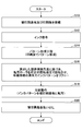
- FIG. 5 shows an example of a printing process performed by the printing apparatus 100 according to the embodiment.
- the control device 200 mounts the substrate to be printed (work board Pw) and the printing plate Pr on the printing device 100 (step S10).
- the work plate Pw is placed on the work table Tw
- the printing plate Pr is placed on the master table Tm and fixed.
- a fixing method a vacuum chuck or a mechanical fixing method can be used.
- control device 200 applies ink from the ink coater Ict to the blanket Bk on the surface of the transfer roller 5 (see step S12, FIG. 6A).
- control device 200 synchronizes the transfer roller 5 and the master table Tm at the same speed, and removes unnecessary ink from the ink on the blanket Bk with the printing plate Pr (step S14, FIG. 6). (See (b)). As a result, a reverse pattern of the pattern formed on the printing plate Pr is formed on the ink Ik applied to the blanket Bk.
- the rotation speed of the transfer roller 5 is controlled based on the calculated limit inclination angle described later, and the vapor atmosphere of the organic solvent OL is supplied from the atmosphere control means 400 to the buffer space U.
- the ink Ik is mixed with the organic solvent OL in the vapor atmosphere of the organic solvent OL supplied from the atmosphere control means 400, and the ink Ik is reflowed (step S16, FIG. 6 (c). )reference).
- control device 200 synchronizes the transfer roller 5 and the work table Tw at the same speed, and transfers the ink Ik pattern reflowed immediately before printing onto the work board Pw (step S18).
- FIG. 6 (d) The printed substrate to be printed (work board Pw) is unloaded from the printing apparatus 100 (step S20). Thereby, the printing of the ink pattern performed by the printing apparatus 100 according to the present embodiment is completed.
- the atmosphere control unit 400 is provided integrally with the printing apparatus 100 in proximity to the printing apparatus 100 with a slight gap therebetween.
- the surface of the ink Ik before transfer can be reflowed, and the ink Ik can be made into a smooth state having a tilt angle equal to or less than the limit inclination angle.
- the limit tilt angle is the limit tilt at which the transfer roller 5 can always contact the other substrate to be printed when the transfer roller 5 rolls relative to the substrate to be printed (work plate Pw) during transfer. It is a horn.
- the side wall angle of the concavo-convex structure of the ink pattern on the work board Pw is set to be equal to or less than the limit inclination angle, so that the printing substrate and the printed substrate can be printed on the work board Pw having the concavo-convex structure. It is possible to prevent the ink pattern from being lost due to the incomplete contact state with the transfer roller 5, and to print the pattern while maintaining high resolution and dimensional accuracy. Thereby, disconnection of a pattern and partial omission of a pattern are made difficult to occur, and the fidelity of pattern printing can be improved.
- the atmosphere control unit 400 is attached in the vicinity of the transfer roller 5, and as shown in FIGS. Transcribed to Pw.
- the surface of the ink pattern is exposed to the vapor atmosphere of the organic solvent before the pattern transfer as in this embodiment, rather than exposing the surface of the ink pattern to the vapor atmosphere of the organic solvent. It is preferable to expose the surface of the ink pattern.
- the step coverage may not be improved depending on the unevenness of the underlying film, and pattern disconnection or partial omission of the pattern may occur.
- the step coverage becomes high, that is, the inclination angle of the side wall becomes smaller than the limit inclination angle.
- the disconnection of the pattern and the partial omission of the pattern are remarkably difficult to occur.
- the atmosphere control unit 400 is attached in the vicinity of the transfer roller 5 and integrated with the printing apparatus 100. Thereby, compared with the case where the printing apparatus 100 and the atmosphere control means 400 are arrange
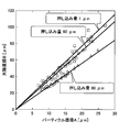
- Fig. 8 shows the relationship between the diameter of the silica ball and the diameter of the circular defect formed by using the pushing amount as a parameter.
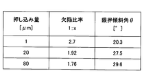
- the slope of the straight line shown in FIG. 8 is that the diameter A of the silica ball Pa shown in the lower right of FIG. 7 when the push-in amount is 1 ⁇ m, 60 ⁇ m, and 80 ⁇ m is heightened, and the diameter B of the circular defect thus formed is the bottom surface.
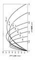
- This side wall angle ⁇ is the so-called limit inclination angle ⁇ for the blanket Bk shown in FIG. 9, and if the unevenness has a gentler inclination than this angle, the surface of the blanket Bk will surely come into contact with the counterpart material. .
- the limit inclination angle ⁇ changes depending on the blanket material, that is, the material characteristics of the blanket and the amount of pushing in the blanket, and therefore needs to be calculated in advance every time the blanket used in the printing apparatus 100 is changed. If it is a blanket equivalent to Sylplan made by Kinyo Co., Ltd. used in this embodiment, the inclination 20 ° in the case of 1 ⁇ m with the smallest push-in amount may be set as the limit inclination angle ⁇ .
- FIG. 10 shows a cross-sectional structure diagram of the substrate to be printed.
- the step coverage of the insulating film DI on the wiring PT formed on the base film UL of the substrate to be processed varies depending on the density of the wiring. Therefore, without the reflow in the upper part of FIG.
- the side wall angle ⁇ 1 of the region P1 where the width of the wiring PT is narrow and the side wall angle ⁇ 2 of the region P2 where the width of the wiring PT is large are greatly different. It exceeds the limit inclination angle ⁇ when the pattern is formed. For this reason, pattern loss is likely to occur at a portion exceeding the limit inclination angle ⁇ .
- a reflow process is added when forming the insulating film DI so that the side wall angle ⁇ of the insulating film DI on the wiring is lowered.
- high temperature heat treatment is performed.
- the insulating film DI is softened, and the unevenness that emerges on the surface of the insulating film DI due to the unevenness of the wiring PT is smoothed more smoothly.
- the thickness of the insulating film DI is somewhat reduced, and the side wall angles ⁇ 3 and ⁇ 4 are also reduced.
- the side wall angles ⁇ 3 and ⁇ 4 of the irregularities generated on the surface of the insulating film DI can be made equal to or less than the limit inclination angle ⁇ .
- the insulating film DI may be formed while softening the insulating film DI in the same process. What is important is that the insulating film DI is formed such that the side wall angles ⁇ 3 and ⁇ 4 of the irregularities formed on the surface of the insulating film DI are equal to or less than the limit inclination angle ⁇ .
- the insulating film DI may be transferred and formed on the substrate to be printed while the insulating film pattern on the transfer roller 5 is reflowed.
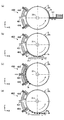
- FIG. 11 shows the results of examining the cross-sectional shape of the pattern formed above and the inclination angle at each point of the cross-sectional profile.
- the inclination angle of the PVP film exceeds 20 ° at the maximum, and it can be seen that the side wall lacks smoothness.
- the inclination angle is further increased in the portion where the projection is generated at the edge of the pattern.
- the blanket cannot be deformed according to the step, and disconnection or missing occurs.
- FIG. 11 shows the lower part of FIG. 11 shows the cross-sectional shape and the side wall angle of the PVP film after the atmosphere control means 400 performs the reflow process according to the present embodiment.
- the contents of the reflow process are as follows.
- the patterned PVP film was exposed to a saturated vapor atmosphere of acetone at 160 ° C. for 5 seconds. Thereafter, the PVP film was fired and modified.
- Acetone is an example of an organic solvent.
- the cross-sectional shape of the surface of the PVP film is changed from the rectangle shown in the graph a-1 in FIG. 11 to the triangle shown in the graph b-1 in FIG. Change to shape. Further, as shown in the graph b-2 in FIG.
- the sidewall angle is 10 ° or less at the maximum.
- the shape collapses for example, the line width increases by about 10%.
- the density of the material is improved, it has favorable characteristics as an interlayer insulating film, such as improved withstand voltage characteristics.
- the lower part of 12 is shown schematically. Since the side wall angle of the unevenness is equal to or smaller than the limit inclination angle ⁇ , the pattern is transferred to the substrate to be printed without disconnection or defect.
- the result when printing is performed on the PVP film (insulating film DI) on the substrate to be processed having the cross-sectional structure shown in the case of reflow in the lower part of FIG. 10 is schematically shown in the upper part of FIG. Since the PVP film is not subjected to the reflow process, there is an unevenness having a side wall with a limit inclination angle ⁇ or more. Therefore, there is a place where the blanket Bk cannot contact the counterpart material, and the ink IK on the blanket Bk does not contact the surface of the counterpart PVP film as shown in the upper part of FIG.
- the limit inclination angle ⁇ that the transfer roller 5 always contacts when the transfer roller 5 rolls relatively on the substrate to be printed is calculated, and the unevenness on the substrate to be printed is calculated.
- a step of executing a reflow process for setting the side wall angle of the structure to be equal to or smaller than the limit inclination angle ⁇ before transferring the ink was added.
- the ink Ik on the surface of the transfer roller 5 always comes into contact with the uneven surface of the substrate to be printed and relatively rolls, and the substrate to be printed and the transfer roller 5 always come into contact with each other, and the printing pattern is missing. Is avoided. As a result, a pattern with high resolution and dimensional accuracy can be printed.
- a printable polyvinylphenol PVP film is used as an interlayer insulating film material, and the printing apparatus 100 described in FIG. 1 is used as the printing apparatus 100.
- a line pattern is formed on the blanket Bk using a printing plate in which an insulating film ink for printing is applied on the blanket Bk with a coater.
- the printing insulating film ink is the printing insulating film ink described in Japanese Patent No. 5617189.
- the film thickness of the printing insulating film ink is 0.6 ⁇ m to 0.7 ⁇ m.
- acetone or tetradecafluorohexane (Fluorinert TM FC-72) is used as an example of the organic solvent, and the reflow treatment is performed on the printing insulating film ink on the blanket.
- the boiling points of acetone and Fluorinert TM FC-72 are both 56 ° C.
- Acetone and printing insulation film ink are mixed (being mixed and indistinguishable), but Fluorinert TM FC-72 and printing insulation film ink are not mixed.
- the insulating film ink pattern for printing was transferred to the glass substrate after the reflow treatment. The transferred pattern was measured with a step gauge.
- Condition 1 One type of pattern size 100 ⁇ m No reflow condition 2
- Type of organic solvent Acetone or Fluorinate TM FC-72 Based on Condition 1, the cross-sectional shape of the insulating film ink for printing when the organic solvent was not subjected to reflow treatment using acetone was examined.
- the insulating film ink for printing was applied on the blanket Bk with a slit coater, and a pattern with a line width of 100 ⁇ m was formed with a printing plate. Thereby, the pattern was transferred onto the glass substrate, and the cross-sectional shape was measured with a step gauge. The results are shown in FIG.
- FIG. 14 shows the experimental results when reflow treatment was performed with acetone or Fluorinert TM FC-72.
- the boiling points of acetone and Fluorinert TM FC-72 are both 56 ° C.
- Fluorinert TM FC-72 which is one of organic solvents, is immiscible with the printing insulating film ink, so even if the heating time is increased, the surface of the printing insulating film ink is not reflowed.
- the maximum inclination angle is 20 ° or more.
- the insulating film ink for printing was applied onto the PDMS blanket Bk with a slit coater, and seven types of patterns with line widths of 20 ⁇ m, 30 ⁇ m, 40 ⁇ m, 50 ⁇ m, 60 ⁇ m, 80 ⁇ m, and 100 ⁇ m were formed using the printing apparatus 100.
- the type of organic solvent used was acetone.
- the insulating film ink for printing is exposed to an acetone saturated vapor atmosphere heated to 60 ° C. for 7 seconds. After the pattern color returns to the color after acceptance (remove unnecessary ink with the printing plate), it is transferred to the glass substrate. Measured with a step gauge. The experimental results are shown in FIGS.
- the ink pattern was transferred onto the glass substrate, it was examined whether or not an appropriate reflow would occur in the printing insulating film ink when the ink pattern was exposed to an atmosphere of saturated vapor pressure of acetone.
- the insulating film ink for printing was applied to the blanket Bk with a slit coater, and a pattern with a line width of 100 ⁇ m was formed with a printing plate.
- a 100 ⁇ m ink pattern was transferred onto a glass substrate (glass that had been cleaned with ultraviolet rays), and then exposed to a saturated vapor atmosphere of acetone at 60 ° C. for 10 seconds. Thereafter, the pattern was measured with a step gauge. The measurement results are shown in FIG. As shown in FIG.
- the printing insulating film ink is reflowed even when the ink pattern is exposed to an atmosphere of saturated vapor pressure of acetone.
- the cross-sectional shape of the ink pattern after reflow is somewhat rougher than the printing method according to the present embodiment, and the side wall angle is also slightly larger. That is, when the printing method according to the present embodiment is executed under the same conditions, that is, in the case of the printing method of the present embodiment in which the ink pattern after being exposed to the atmosphere of the saturated vapor pressure of the organic solvent is transferred to the substrate, FIG. As shown in FIG. 19, the effect of reflow on the ink is clearly high.
- the side wall angle of the ink surface is small and there is no variation, the ink surface is smooth, and there are few irregularities.
- the side wall angle of the pattern can be reduced by reflowing the ink material by exposing it to an atmosphere of saturated vapor pressure of an organic solvent mixed with the ink material.
- the limit inclination angle ⁇ that the transfer roller 5 always contacts when the transfer roller 5 rolls relatively on the substrate to be printed is calculated, and the side wall of the uneven structure of the ink on the substrate to be printed is calculated. The angle is reconstructed to be equal to or less than the limit inclination angle ⁇ .
- the surface of the transfer roller 5 always comes into contact with the concavo-convex surface of the substrate to be printed and rolls relatively, and the substrate to be printed and the transfer roller 5 always come into contact with each other, resulting in a missing print pattern.
- the pattern can be printed while maintaining high resolution and dimensional accuracy.
- the ink material after reflow is transferred to the substrate.
- the fidelity of pattern printing can be improved.
- Organic solvent can be applied to the printing method according to the present embodiment as long as it is a solvent shown below that can be mixed with the ink applied to the blanket Bk.
- polyvinylphenol resin which is a resin component contained in the ink has a certain solubility, for example, pentane, hexane, heptane, octane, decane, dodecane, isopentane, isohexane , Isooctane, cyclohexane, methylcyclohexane, cyclopentane and other aliphatic hydrocarbon organic solvents, benzene, toluene, o-xylene, m-xylene, p-xylene, ethylbenzene, mesitylene, naphthalene, cyclohexylbenzene, diethylbenzene and other aromatics Hydrocarbon solvents, ester solvents such as methyl formate, ethyl formate, propyl formate, methyl acetate, ethyl acetate, is
- Ether solvents such as N, N-dimethylformamide, N, N-dimethylacetamide, N-methylpyrrolidone, and the like, but are not particularly limited. These may be used alone or in combination of two or more. Of course, with these various solvents, a solvent that does not adversely affect the printed substrate on which the insulating pattern is formed and other functional patterns can be appropriately selected.
- Reflow of reversal printed nano Ag (metal) ink pattern Various solvents that can reflow the printed pattern before sintering to a conductor by thermal firing, Xe flash, IR, etc. can be used.
- DIC nano Ag ink RAGT series RAGT15-28
- a dispersion solvent with relatively high polarity alcohols such as water, methanol, ethanol, butyl alcohol, methoxybutanol and tertiary butanol
- ethylene Polyhydric alcohols such as glycol, propylene glycol, diethylene glycol, glycerin
- esters such as ethyl acetate, methyl acetate, isobutyl acetate, ethyl lactate, and carbonates such as propylene carbonate
- Ketones such as acetone, methyl ethyl ketone, methyl butyl ketone, methyl isobutyl ketone, cyclohexanone, diacetone alcohol; methyl cellosolve, cellosolve, butyl celloso Glycol ethers such as diethylene glycol monomethyl ether, dipropylene glycol monomethyl ether, propylene glycol monomethyl ether and propylene glycol monoethyl ether; glycol acetates such as ethylene glycol monomethyl ether acetate; glycol dimers such as methyl triglyme and ethyl monoglyme Ethers; cycloaliphatic hydrocarbons such as cyclohexanone, methylcyclohexanone, cyclohexanol, methylcyclohexanol; aliphatic hydrocarbons such as normal hexane; aromatic hydrocarbons such as toluene and xylene; chlor
- the transfer printing apparatus and the transfer printing method have been described in the above embodiment.
- the transfer printing apparatus and the transfer printing method according to the present invention are not limited to the above embodiment, and various modifications can be made within the scope of the present invention. And improvements are possible.
- the matters described in the above embodiments can be combined within a consistent range. For example, sufficient effects can be obtained in the following cases.
- the blanket Bk or the substrate may be heated for several seconds in a non-solvent atmosphere to prevent condensation.
- the solvent used for the reflow may be mixed with the ink and may not be acetone. In the reflow step, it is desirable that the solvent has a low boiling point in order to prevent the ink from adhering to the base film.
- the ink immediately before reflowing may be in a state where it can be dissolved or redispersed again by contacting with the solvent used for reflow, and is generally referred to as dry (with a volume solid content of 30% to 80%) %) Is desirable.
Landscapes
- Engineering & Computer Science (AREA)
- Mechanical Engineering (AREA)
- Printing Methods (AREA)
- Manufacturing Of Printed Wiring (AREA)
Abstract
転写ローラ上のブランケットに塗布したインクのパターンを被印刷基板に印刷する転写印刷装置であって、前記転写ローラに近接した位置に設けられ、所定の有機溶媒を導入し、前記ブランケットに塗布したインクに向けて供給する導入口と、前記有機溶媒を排気する排気口とを有する雰囲気制御手段を有する転写印刷装置により、パターン印刷の忠実性を高めた。
Description
本発明は、転写印刷装置及び転写印刷方法に関する。
ディスプレイ等で使われる電子デバイスの回路パターンをガラス基板やフィルム基板等の被印刷基板上に形成する一手法として、転写印刷方法が提案されている。このようなデバイスのパターンには、ディスプレイの画素の微細化に伴って高い解像性や寸法精度、パターン信頼性が要求されるようになってきている。被印刷基板に高い解像性や寸法精度を有するパターンを印刷できる転写印刷方法としては、反転印刷法が挙げられる(例えば、特許文献l参照。)。
この反転印刷法には、ローラ転写胴(以下、「転写ローラ」ともいう。)を用いることがある。転写ローラを用いた反転印刷法では、シリコーン樹脂層を表面とする転写ローラの表面にインクを塗布して塗布面を形成する塗布工程と、塗布工程後の転写ローラを、所定のパターンを有する印刷版上で転動させ、印刷版の凸部に対応する塗布面のインクを除去する除去工程と、塗布面に残っているインクを被印刷基板に転写する転写工程とを行う(例えば、特許文献2参照。)。
転写ローラを用いた反転印刷法では、ガラス板よりなる印刷版と転写ローラとを相対移動させ、印刷版上で転写ローラを転動させることによって、印刷版のパターンを転写ローラに転写する。次いで、被印刷基板と転写ローラとを相対移動させ、被印刷基板上で転写ローラを転動させることによって、転写ローラ上のインクパターンを被印刷基板に転写する。この手法によれば、フォトリソグラフィ法により形成されるパターン並みの解像性が容易、かつ安価に得られる。
一方、反転印刷法では段差被覆性に劣る、すなわち凹凸構造を持つ被印刷基板上への印刷においてパターンの断線やパターンの一部欠落が起き易いという課題を有する。そこで、特許文献3には、インクのパターンを印刷後、有機溶媒の雰囲気中にインクのパターンを曝露するか、或いは熱等の処理によってパターン化されたインクを、有機溶媒の雰囲気に曝露して軟化させることが提案されている。
しかしながら、印刷後のインクパターンを有機溶媒の雰囲気中に曝露してインクを軟化させた場合、インクの下地膜の凹凸の状態によっては段差被覆性が改善されず、パターンの断線やパターンの一部欠落が生じ得る。他方、印刷前のインクを軟化させてから印刷すると、段差被覆性が高くなり、パターンの断線やパターンの一部欠落が起き難くなる。
上記課題に対して、一側面では、本発明は、パターン印刷の忠実性を高めることを目的とする。
上記課題を解決するために、一の態様によれば、転写ローラ上のブランケットに塗布したインクのパターンを被印刷基板に印刷する転写印刷装置であって、前記転写ローラに近接した位置に設けられ、所定の有機溶媒を導入し、前記ブランケットに塗布したインクに向けて供給する導入口と、前記有機溶媒を排気する排気口とを有する雰囲気制御手段を有する、を有する転写印刷装置が提供される。
一の側面によれば、パターン印刷の忠実性を高めることができる。
以下、本発明を実施するための形態について図面を参照して説明する。なお、本明細書及び図面において、実質的に同一の構成については、同一の符号を付することにより重複した説明を省く。
[転写印刷装置]
一実施形態にかかる印刷装置100について、図1及び図2を参照して説明する。図1は、一実施形態にかかる印刷装置100の一例を示す。図2は、一実施形態にかかる印刷装置100に設けられた雰囲気制御手段の一例を示す。
一実施形態にかかる印刷装置100について、図1及び図2を参照して説明する。図1は、一実施形態にかかる印刷装置100の一例を示す。図2は、一実施形態にかかる印刷装置100に設けられた雰囲気制御手段の一例を示す。
図1に示す印刷装置100は、転写ローラ5上のブランケットBkに塗布したインクにより印刷版Prに形成されたパターンを被印刷基板(以下、「ワーク板Pw」ともいう。)に印刷する転写印刷装置の一例である。印刷装置100は、反転印刷により電子デバイス用の回路パターン(プリンテッドエレクトロニクスデバイスなど)の印刷を行う。また、印刷装置100は、例えば半導体製造装置においてラインアンドスペース等のパターンを被印刷基板上に形成する製造装置として用いることができる。ただし、転写印刷装置は、図1に示す印刷装置100の構成に限定されるものではなく、種々の設計変更が可能である。
図1において、X方向は、マスターテーブルTm及びワークテーブルTwが移動する方向である。Y方向は、X方向に直交する方向で、マスターテーブルTm及びワークテーブルTwの幅方向を示す。Z方向は、鉛直方向(X方向とY方向に直交する方向)である。ω方向は、Z軸を中心とした回転方向である。
印刷装置100は、転写ローラ5を有する。転写ローラ5は、ローラ支持部Bkpに支持され、回転軸31rを中心軸として回転可能である。転写ローラ5は、その外周にブランケットBkが巻回されたブランケット胴とされている。インクコータIctはブランケットBkに固定されている。インクコータIctは、ブランケットBkの表面にインクを供給する(図6(a)参照)。これにより、ブランケットBkの印刷領域にインク膜が形成される。印刷装置100は、インク膜を印刷版Prで部分的に除去して印刷版Prの反転パターン(以下、「インクパターン」ともいう。)を形成し、その後、反転パターンをワーク板Pwに転写する。
印刷版Prは、ブランケットBk上のインク膜から所定のインクを受理させて除去するための凸パターンが形成されたマスター版である。印刷版Prは、マスターテーブルTm上に固定されている。ワーク板Pwは、平板状のフィルムやガラス基板等の被印刷基板の一例である。ワーク板Pwには、ブランケットBk上に形成されたインクパターンが転写される。ワーク板Pwは、ワークテーブルTw上に固定されている。
印刷装置100は、転写ローラ5の回転動作と印刷版Prの直進動作とを同期させて転写ローラ5に巻き付けられたブランケットBkの表面に反転パターンを形成する。そして、印刷装置100は、転写ローラ5の回転動作とワーク板Pwの直進動作とを同期させてブランケットBkの表面に形成された反転パターンをワーク板Pwに印刷(転写)する。ブランケットBkの全面領域又はブランケットBkの外周側を除いた領域が印刷領域である。
転写ローラ5の端部にはピニオン12が取り付けられ、回転軸31rの一端に取付けられたクラッチ7で回転軸31rと連動又は非連動させることにより転写ローラ5の回転動作を制御するようになっている。回転軸31rの他端にはブランケットBkに固定された回転駆動用の減速機付駆動部6が連結されている。クラッチ7をつなげると転写ローラ5とピニオン12が連動して回転し、クラッチ7を切ると転写ローラ5だけが回転するようになっている。ブランケットBkの全体は、上下機構14によってZ方向に上下動する。これにより、ラック2とピニオン12との関係は、噛合、離間、分離の三状態を選択することができる。
本体9上にはラック2と平行した直線軸受のリニアガイドGdが固定され、その上を連結されたマスターテーブルTm及びワークテーブルTwが移動自在に固定されている。リニアガイドGdは、マスターテーブルTm及びワークテーブルTwを、転写ローラ5の下方までX方向に直進移動させる。かかる構成の印刷装置100は、転写ローラ5に対する印刷版Prとワーク板PwとのZ方向の間隔、X方向のずれ、印刷版Prとワーク板PwとのY方向の距離を調整することができる。また、Z軸周りの回転方向に微動可能な機構を組み込むことにより、ω方向(Z軸を中心とした回転方向)の傾きを調整することができる。
次に、印刷装置100の動作について簡単に説明する。まず、連結したマスターテーブルTm及びワークテーブルTwを原点(図1のテーブル位置の状態)に戻し、そこで印刷版PrをマスターテーブルTmの所定位置に固定し、ワーク板PwをワークテーブルTwの所定位置に固定する。固定方法は、真空チャックや機械式固定法などを用いることができる。
次に、転写ローラ5に対する印刷版Prとワーク板PwとのZ方向の間隔、X方向のずれ、ω方向の傾き、印刷版Prとワーク板PwとのY方向の距離などを調整する。これにより、転写ローラ5の回転と同期して転写ローラ5のブランケットBk上のインクの受理及び転写を、印刷版Pr及びワーク板Pwとの間で行うことができる。印刷においては、上下機構14を動作させることで、ブランケットBkを上昇させ、ピニオン12とラック2の歯が噛合わないように完全に分離する。クラッチ7を切って減速機付駆動部6で転写ローラ5を回転させ、転写ローラ5を原点位置に戻す。
所定の位置でインクコータIctを転写ローラ5に近づけ、インクコータIctの先端と転写ローラ5上のブランケットBkの表面との間隔を設定値にする。転写ローラ5をさらに回転させ、インクコータIctからインクを供給し、メニスカス法により転写ローラ5の表面の必要な面積領域に一定膜厚のインク膜を形成する。インク膜の形成後、インクコータIctを所定の位置まで戻す。
転写ローラ5をさらに回転させ、所定の位置でクラッチ7を接続し、上下機構14を動作させてブランケットBkを下降させ、ラック2とピニオン12を噛合わせる。減速機付駆動部6を動作させ転写ローラ5をマスターテーブルTm及びワークテーブルTwと連動させて動かす。ラック2とピニオン12が噛合し、転写ローラ5とピニオン12との半径は一致させてあるので、転写ローラ5の外周速度はマスターテーブルTmの移動速度と一致する。このため、マスターテーブルTm上の印刷版Prは、ほぼ線上に接触する領域で印刷版Prの凸領域表面でブランケットBkに塗られたインク膜から接触したインクをはぎ取るように進んでいく。この結果、ブランケットBkの表面には、印刷版Prの反転パターンのインクが残ることになる。
次に、上下機構14でブランケットBkを上昇させ、ラック2とピニオン12との噛合を解除し、転写ローラ5を所定の位置まで回転させ、その後、再び上下機構14でブランケットBkを下降させ、ラック2とピニオン12とを噛合させる。減速機付駆動部6により転写ローラ5とワークテーブルTwとを連動させて動かす。これにより、ブランケットBk上のパターン化されたインク膜がワーク板Pw上に転写される。以上の動作を繰り返すことにより、ワーク板Pw上にインクパターンを重ね印刷して、電子デバイスの回路パターンを被印刷基板に作製する。
転写ローラ5に近接した位置には、雰囲気制御手段400が設置されている。印刷装置100は、制御装置200により制御される。制御装置200は、CPU201(Central Processing Unit)、ROM202(Read Only Memory)、RAM203(Random Access Memory)及びHDD(Hard Disk Drive)を有する。制御装置200は、雰囲気制御手段400が供給する有機溶媒のリフロー時間を制御する制御信号を制御I/F機構300に出力する。制御I/F機構300は、制御信号に基づき、転写ローラ5の回転速度を制御する。
制御I/F機構300は、制御装置200からの指示を受け付け、転写ローラ5の回転速度が所望の速度になるように減速機付駆動部6を制御する。減速機付駆動部6の駆動により、転写ローラ5は、所望の回転速度で回転する。これにより、ブランケットBkに塗布されたインクを、雰囲気制御手段400が供給する有機溶媒の蒸気雰囲気によりリフローする時間を制御することができる。
かかる構成の印刷装置100では、雰囲気制御手段400が実行する有機溶媒によるリフローによって、パターン印刷の忠実性を向上させることができる。なお、本実施形態において「リフロー」とは、雰囲気制御手段400から供給された有機溶媒の蒸気雰囲気にインクを暴露することをいう。リフローによりインクを軟化させて、インクの表面を滑らかにする処理をリフロー処理といい、有機溶媒の蒸気雰囲気にインクを暴露する時間をリフロー時間という。
[雰囲気制御手段]
次に、雰囲気制御手段400の構成の一例について、図2及び図3を参照しながら更に詳しく説明する。図2は、雰囲気制御手段400の内側面(転写ローラ5に対向している面)を示す。図3は、図2のA-A断面を示す。
次に、雰囲気制御手段400の構成の一例について、図2及び図3を参照しながら更に詳しく説明する。図2は、雰囲気制御手段400の内側面(転写ローラ5に対向している面)を示す。図3は、図2のA-A断面を示す。
図3に示すように、雰囲気制御手段400は、転写ローラ5に近接する側に設けらえたバッファ空間Uにおいて、転写ローラ5上のブランケットBkに塗布されたインクパターンにリフロー処理を行うようになっている。
図2及び図3に示すように、雰囲気制御手段400の中央には、有機溶媒を導入する導入口401aを有する動入管401が形成されている。ただし、導入口401aの位置及び個数は、これに限らず、雰囲気制御手段400のサイズ及び形状に応じて有機溶媒を導入するために適した位置に所望の個数だけ設けられることが好ましい。図3に示すように、導入口401aは、雰囲気制御手段400の筐体410を貫通している。これにより、有機溶媒は、導入口401aから導入され、ブランケットBkに塗布されたインクIkに向けて供給されるようになっている(図6(c)参照)。
雰囲気制御手段400の筐体410には、転写ローラ5に近接する側の面に凹み部410aがある。これにより、凹み部410aとブランケットBkの表面との間にバッファ空間Uが形成される。バッファ空間Uでは、雰囲気制御手段400に導入された有機溶媒の蒸気雰囲気が滞留し、これにより、印刷領域に塗布されたインクと混和してインクを軟化させる。導入する有機溶媒蒸気の圧力を凹み部410aに取り付けられた圧力計、例えばダイアフラム型圧力計420でモニターしながら調整する。
雰囲気制御手段400の外縁には、有機溶媒を排気する排気口402a、403aを有する排気管402,403が形成されている。図2に示すように、排気管402,403は、雰囲気制御手段400の外縁に枠状に内側と外側とに形成されている。排気口402a、403aは、排気管402,403の上下中央及び左右中央にそれぞれ形成されている。ただし、排気口402a、403aの位置及び個数は、これに限らず、雰囲気制御手段400のサイズ及び形状に応じて有機溶媒を排気するために適した位置に所望の個数だけ設けられることが好ましい。また、排気口402a、403aの位置は、導入口401aの位置よりも外側であって、バッファ空間Uを形成する凹み部410aよりも外側であることが好ましい。
本実施形態では、図3に示すように、排気口402a、403aは、凹み部410aの外側の部分であって、筐体410が凹み部410aよりも厚くなった部分を貫通している。後述されるように、雰囲気制御手段400は、導入口401aから圧力P1で有機溶媒蒸気を導入し、排気管402とブランケットBkとのギャップ402gapから漏れ出る蒸気を排気管402で吸気し、排気口402aから排気する。さらに排気管402で吸気し切れなかった蒸気が排気管403とブランケットBkとのギャップ403gapから漏れ出てくるので排気管403で吸気し、排気口403aから排気する。このような差動排気機構を設けることにより有機溶媒蒸気が筐体410の外へ漏れ出ることを防ぐことができる。このため排気に用いるポンプは低圧で大きな排気容量を持つドライポンプを使用することが好ましい。
また、図2に示すように、雰囲気制御手段400には、湿度センサ501、温度センサ502及びダイアフラム型圧力計503が設けられている。湿度センサ501は、雰囲気制御手段400の湿度を所定時間毎に検知し、検知した湿度値を制御I/F機構300に送信する。温度センサ502は、雰囲気制御手段400の温度を所定時間毎に検知し、検知した温度値を制御I/F機構300に送信する。ダイアフラム型圧力計503は、雰囲気制御手段400に導入する有機溶媒蒸気の圧力を所定時間毎に検知し、検知した圧力値を制御I/F機構300に送信する。制御I/F機構300は、これらの湿度値、温度値及び圧力値を制御装置200に送信する。制御装置200は、湿度値、温度値及び圧力値に基づき、ブランケットBk上のインクの状態を予測し、有機溶媒をリフローする時間を決める回転速度を決定してもよい。
[有機溶媒の供給]
雰囲気制御手段400と転写ローラ5とのギャップは、筐体410の排気口402aのギャップ402gap、及び排気口403aのギャップ403gapが形成された部分において、30μm~100μm程度である。ただし、ギャップの大きさは、これに限らず、有機溶媒を排気口402a、403aから確実に排気できる隙間であればよい。ギャップ402gapと403gapを異なるように筐体410を作製してもよい。ただし、転写ローラ5は、インクをブランケットBkに塗布した状態で回転するため、雰囲気制御手段400は、転写ローラ5を回転したときに転写ローラ5上のインクIkと接触しない程度の隙間が必要である。
雰囲気制御手段400と転写ローラ5とのギャップは、筐体410の排気口402aのギャップ402gap、及び排気口403aのギャップ403gapが形成された部分において、30μm~100μm程度である。ただし、ギャップの大きさは、これに限らず、有機溶媒を排気口402a、403aから確実に排気できる隙間であればよい。ギャップ402gapと403gapを異なるように筐体410を作製してもよい。ただし、転写ローラ5は、インクをブランケットBkに塗布した状態で回転するため、雰囲気制御手段400は、転写ローラ5を回転したときに転写ローラ5上のインクIkと接触しない程度の隙間が必要である。
次に、図4を参照しながら、本実施形態にかかる雰囲気制御手段400及びその近傍の構成の一例及び有機溶媒の供給について説明する。雰囲気制御手段400の下部には、雰囲気制御手段400を支持し、その位置を調整する位置調整機構420が設置されている。位置調整機構420は、位置調整機構420の伸縮により雰囲気制御手段400の高さを調整する。また、位置調整機構420は、水平方向にスライド移動することで、雰囲気制御手段400の水平方向の位置を調整する。
排気管402の4つの排気口402aのそれぞれは、配管502を介して排気ポンプP1に連結されている。排気管403の4つの排気口403aのそれぞれは、配管503を介して排気ポンプP2に連結されている。排気ポンプP1、P2により、排気管402、403の内部は排気され、導入管401の内部よりも減圧された状態になる。このようにして、雰囲気制御手段400は、導入口401aから導入管401内部を通って導入された有機溶媒蒸気の圧力を一定に保ちつつ、ギャップ402gapとギャップ403gapから漏れ出てくる蒸気を排気管402、403を介して排気口402a、403aから回収する2段構成の差動排気機構になっている。
有機溶媒OLは、液体の状態でリザーブタンク610に保存されている。リザーブタンク610は蒸気発生器600に接続されている。リザーブタンク610と蒸気発生器600とを接続する配管に設けられたバルブ620を開くと、有機溶媒OLがリザーブタンク610から蒸気発生器600に供給される。蒸気発生器600には、ヒータ530が設けられている。蒸気発生器600に供給された有機溶媒OLは、ヒータ530により加熱され、蒸発し、液体から気体になる。これにより、蒸気発生器600にて有機溶媒OLの蒸気が生成される。
蒸気発生器600にて生成された有機溶媒OLの蒸気は、配管630を通り、バルブ621を開くと、配管630の内部を通り、導入口401aからバッファ空間Uに供給される。配管630には、パージライン700が接続されている。パージライン700に設けられたバルブ623を開くと、パージライン700から供給されるパージガス、例えばN2ガスが配管630の内部に供給される。これにより、有機溶媒OLの蒸気が配管630からバッファ空間Uまで速やかに運ばれ、配管630内がN2ガスに置換される。パージラインは、配管630等のガスラインの洗浄等に用いられる。配管630及びバルブ621にはヒータ520が取り付けられている。これにより、配管630及びバルブ621は所定の温度に制御され、有機溶媒OLの蒸気が、配管630の内部を移動する際に、冷却されて液体になり、配管630に付着することを回避することができる。
以上説明したように、雰囲気制御手段400は、蒸気発生器600を有し、蒸気発生器600にて発生した有機溶媒OLの蒸気雰囲気を配管630に通して、導入口401aからブランケットBk上のインクに向けて供給することができる。
蒸気発生器600は、導入口401aに接続され、有機溶媒OLを蒸気にする蒸気機構の一例である。ヒータ530は、加熱手段の一例であり、例えばシーズヒータにより構成されてもよい。蒸気発生器600は、導入口401aの近傍に設けられていることが好ましい。
雰囲気制御手段400の筐体410の内部又は表面には、ヒータ510が組み込まれていてもよい。ヒータ510は、有機溶媒の温度制御を行う加熱手段の一例である。ヒータ510により、導入口401aから供給する有機溶媒OLの蒸気の温度を調整することができる。同様に、転写ローラ5には、ヒータ500が組み込まれていてもよい。ヒータ500は、ブランケットBk上のインクを加熱する加熱手段の一例である。ヒータ500,510は、例えば、カーボンまたはカーボンナノチューブをシート状に形成したヒータであってもよい。
以上のように、ヒータ500、510、520、530は、加熱手段の一例である。例えば、リザーブタンク610にも加熱手段としてのヒータが設けられていてもよい。加熱手段は、雰囲気制御手段400、雰囲気制御手段400に有機溶媒OLを供給する経路(例えば、配管630)及び転写ローラ5の少なくともいずれかの位置に設置されていることが好ましい。ただし、ヒータ500、510、520、530はいずれも必ずしも設けられなくてもよい。
[印刷処理]
図5は、一実施形態にかかる印刷装置100が行う印刷処理の一例を示す。まず、制御装置200は、被印刷基板(ワーク板Pw)及び印刷版Prを印刷装置100に搭載する(ステップS10)。具体的には、図1に示すように、ワーク板PwをワークテーブルTwに載置し、印刷版PrをマスターテーブルTmに載置し、固定する。固定方法は、真空チャックや機械式固定法などを用いることができる。
図5は、一実施形態にかかる印刷装置100が行う印刷処理の一例を示す。まず、制御装置200は、被印刷基板(ワーク板Pw)及び印刷版Prを印刷装置100に搭載する(ステップS10)。具体的には、図1に示すように、ワーク板PwをワークテーブルTwに載置し、印刷版PrをマスターテーブルTmに載置し、固定する。固定方法は、真空チャックや機械式固定法などを用いることができる。
次に、制御装置200は、インクコータIctから転写ローラ5の表面のブランケットBkにインクを塗布させる(ステップS12、図6(a)参照)。
次に、制御装置200は、その状態で、転写ローラ5とマスターテーブルTmとを同期させて同一速度で動かし、ブランケットBk上のインクから不要なインクを印刷版Prで抜き取る(ステップS14、図6(b)参照)。これにより、ブランケットBkに塗布されたインクIkに、印刷版Prに形成されたパターンの反転パターンが形成される。
次に、後述される算出された限界傾斜角に基づき、転写ローラ5の回転速度を制御し、雰囲気制御手段400から有機溶媒OLの蒸気雰囲気をバッファ空間Uに供給する。これにより、図2に示すバッファ空間Uにおいて、雰囲気制御手段400から供給される有機溶媒OLの蒸気雰囲気でインクIkを有機溶媒OLに混和させ、インクIkをリフローさせる(ステップS16、図6(c)参照)。
次に、制御装置200は、その状態で、転写ローラ5とワークテーブルTwとを同期させて同一速度で動かし、印刷直前にリフローされたインクIkのパターンをワーク板Pw上に転写する(ステップS18、図6(d)参照)。印刷された被印刷基板(ワーク板Pw)は、印刷装置100から搬出される(ステップS20)。これにより、本実施形態に係る印刷装置100が行うインクパターンの印刷が完了する。
このように、本実施形態に係る印刷装置100によれば、雰囲気制御手段400は、印刷装置100に近接して、わずかに隙間を空けた状態で一体的に設けられている。これにより、転写前のインクIkの表面をリフローして、インクIkを限界傾斜角以下の滑らかな状態にすることができる。限界傾斜角は、転写時に転写ローラ5が被印刷基板(ワーク板Pw)に対して相対的に転動する際に転写ローラ5が常に相手方の被印刷基板に接触することが可能な限界の傾斜角である。よって、本実施形態に係る印刷処理では、ワーク板Pw上のインクパターンの凹凸構造の側壁角を限界傾斜角以下にすることで、凹凸構造を持つワーク板Pw上への印刷において被印刷基板と転写ローラ5との接触状態が不完全なことに起因してインクパターンの欠落が生じることを防止し、高い解像性と寸法精度を保ちパターンを印刷できる。これにより、パターンの断線やパターンの一部欠落を起き難くし、パターン印刷の忠実性を高めることができる。
また、本実施形態にかかる印刷装置100では、雰囲気制御手段400が転写ローラ5の近傍に取り付けられ、図6(c)及び図6(d)に示すように、リフローした直後のインクがワーク板Pwに転写される。
このように、ワーク板Pwへインクを転写した後に、そのインクパターンの表面を有機溶媒の蒸気雰囲気に曝露するよりも、本実施形態のように、パターンの転写の前に有機溶媒の蒸気雰囲気にインクパターンの表面を曝露する方が好ましい。前者のように転写後のインクパターンを有機溶媒の雰囲気中に曝露させた場合、下地膜の凹凸の状態によっては段差被覆性が改善されず、パターンの断線やパターンの一部欠落が生じ得る。他方、後者のように転写前のインクを有機溶媒の蒸気雰囲気に曝露させ、インクパターンを軟化させてから転写すると、段差被覆性が高くなり、すなわち側壁の傾斜角が限界傾斜角よりも小さくなり、パターンの断線やパターンの一部欠落が顕著に起き難くなる。
また、本実施形態にかかる印刷装置100では、雰囲気制御手段400が転写ローラ5の近傍に取り付けられ、印刷装置100と一体化している。これにより、印刷装置100と雰囲気制御手段400とが別体で配置されている場合と比べて、印刷時間を短縮することができる。
[限界の傾斜角]
印刷装置100の転写ローラ5に巻きつけられたブランケットBkでの限界傾斜角の算出方法の一例について説明する。図7の上部中央に示すように、直径の異なるシリカボールPaをワーク板Pw上にばら撒く。その状態でブランケットBk上に塗布されたインク膜をそのままワーク板Pwに転写する。ブランケットBkのワーク板Pwへの押し込み量を変え、転写実験を繰り返す。
印刷装置100の転写ローラ5に巻きつけられたブランケットBkでの限界傾斜角の算出方法の一例について説明する。図7の上部中央に示すように、直径の異なるシリカボールPaをワーク板Pw上にばら撒く。その状態でブランケットBk上に塗布されたインク膜をそのままワーク板Pwに転写する。ブランケットBkのワーク板Pwへの押し込み量を変え、転写実験を繰り返す。
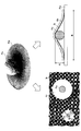
転写実験の結果、図7の下部左側に示すように、介在物(シリカボールPa)が存在することによりワーク板Pw上に転写されたインクIkには円形のパターンのインクが転写されない欠落(欠陥)領域Arが発生する。これはブランケットBkがシリカボールPaを覆いかぶさるようには変形できないためである。従ってシリカボールPaの直径が大きくなればなるほど大きな径を有する円形の欠落領域Arができることになる。シリカボールPaのような異物の周りの、円形のインクの付かない円形の欠落領域Arは、印刷時の欠陥になる。
ブランケットBkの上に異物や段差があったときには、印刷時に欠陥が生じる。よって、本実施形態にかかる印刷方法では、印刷時の異物による欠陥が生じないようにする。また、異物がなくてもインクが付かないことによる印刷時の欠陥が生じないようにする。
押し込み量をパラメータにしてシリカボールの直径とそれにより出来上がる円形欠陥の直径の関係を図8に示す。図8に示された直線の傾きは、押し込み量を1μm、60μm、80μmとしたときの図7の下部右に示すシリカボールPaの直径Aを高さにして、出来上がる円形欠陥の直径Bを底面の直径とした円錐の側壁角αに相当する。この側壁角αが、図9に示すブランケットBkにとってのいわゆる限界傾斜角θであり、この角度よりも緩やかな傾斜を持つ凹凸であればブランケットBkの表面は確実に相手材と接触することになる。
この限界傾斜角θは、ブランケットの材質、すなわちブランケットの持つ材料特性やプランケットの押し込み量によって変化するため、印刷装置100で使われるブランケットが代わるたび毎に予め算出しておく必要がある。本実施形態で使用した金陽社製のシルプラン相当のブランケットであれば、押し込み量を最も小さくした1μmの場合の傾き20°を限界傾斜角θにすればよい。
次に、被印刷基板の持つ凹凸の側壁角を限界傾斜角θ以下にするプロセス処理について示す。印刷法により形成された配線上に層間絶縁膜を介して印刷法により配線を形成する場合を例に挙げて説明する。図10に被印刷基板の断面構造図を示す。被処理基板の下地膜ULに形成された配線PT上の絶縁膜DIは配線の密度に応じて段差被覆性が変わる。そのため、図10の上段のリフローなしでは、配線PTの幅が細い領域P1の側壁角α1と配線PTの幅が太い領域P2の側壁角α2とが大きく異なり、いずれの側壁角も反転印刷法でパターンを形成する際の限界傾斜角θを上回る。このため限界傾斜角θを超える部分でパターンの欠落が生じ易い。
そこで、図10の下段のリフローありでは、絶縁膜DIの形成時にリフロー処理を追加し、配線上の絶縁膜DIの側壁角αが低下するようにする。具体的には高温加熱処理を施す。リフロー処理は、絶縁膜DIを軟化させ、配線PTの凹凸により絶縁膜DI表面に浮き出る凹凸をよりなだらかに平坦化させる。これにより、絶縁膜DIの厚さは多少低下し、それぞれの側壁角α3、α4も低下する。この工程により絶縁膜DIの表面上に生じている凹凸の側壁角α3、α4を限界傾斜角θ以下にすることができる。
なお、ここでは、絶縁膜形成工程とリフロー工程を別々の工程としたが、両者を同一工程内で、絶縁膜DIを軟化しながら絶縁膜DIを形成するようにしてもよい。重要なことは、絶縁膜DIの表面に形成された凹凸の側壁角α3、α4が限界傾斜角θ以下になるように絶縁膜DIを形成することである。例えば、転写ローラ5上の絶縁膜パターンをリフローさせながら被印刷基板上に絶縁膜DIを転写して形成してもよい。
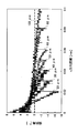
本実施形態のリフロー処理に関し、具体的な実験結果について以下に説明する。実験には、層間絶縁膜の材料として印刷可能なボリビニルフェノールPVPを使った。図1の印刷装置100を使って50μm幅のラインが500μm間隔で並んだラインアンドスペースパターンを作製した。膜厚は約1.5μmであった。図11に上記で形成されたパターンの断面形状と断面プロファイルの各点での傾斜角を調べた結果を示す。リフローせずに印刷したパターンでは、図11のグラフa-2に示すように、PVP膜の傾斜角は、最大で20°を超え、滑らかさに欠ける側壁を持つことがわかる。また、図11のグラフa-1に示すように、パターンのエッジにて突起が生じている部分では、傾斜角はさらに大きくなる。このような傾斜角ではその上にメタル膜を印刷する場合にブランケットがその段差に応じて変形することができず、断線や欠落が生じる。
図11の上段に対して、図11の下段は、雰囲気制御手段400により、本実施形態にかかるリフロー処理を実行した後のPVP膜の断面形状と側壁角とを示す。リフロー処理の内容は以下の通りである。パターニングされたPVP膜を160℃のアセトンの飽和蒸気雰囲気内に5秒間晒した。その後、PVP膜の焼成改質を行った。アセトンは、有機溶媒の一例である。図11のグラフb-1に示すように、リフロー処理を行ったことで、PVP膜の表面の断面形状が、図11のグラフa-1に示す矩形から図11のグラフb-1に示す三角形状に変わる。また、図11のグラフb-2に示すように、側壁角は最大でも10°以下になっている。一方、PVP膜をリフローさせたことで線幅は約l割広がるなど形状が崩れる。反面材料の緻密度が向上するため、耐電圧特性が改善されるなど層間絶縁膜として好ましい特性を持つようになる。
最後に印刷を行う。被印刷基板の凹凸の側壁角が限界傾斜角θ以下となっているのでブランケットBk表面は常に被印刷基板の表面に接触し、インク材をブランケットBkの表面から被印刷基板の表面に欠落や断線等のない転写を実行することができる。
限界傾斜角θ以下の凹凸を持つ、つまり、図10の下段のリフローありの場合に示した断面構造を持つ被処理基板上のPVP膜(絶縁膜DI)に印刷を行った場合の結果を図12の下段に図式的に示す。凹凸の側壁角が限界傾斜角θ以下になっているためパターンは断線や欠損なく被印刷基板に転写される。
一方、図10の下段のリフローありの場合に示した断面構造を持つ被処理基板上のPVP膜(絶縁膜DI)に印刷を行った場合の結果を図12の上段に図式的に示す。PVP膜にリフロー処理を施していないため、限界傾斜角θ以上の側壁を持つ凹凸がある。よって、ブランケットBkが相手材に接触できない箇所があり、図12の上段に示すようにブランケットBk上のインクIKが相手型のPVP膜の表面に接触せず断線等の欠損Deが生じている。
以上に説明したように、本実施形態では、被印刷基板上を転写ローラ5が相対的に転動する際に転写ローラ5が常に接触する限界傾斜角θを算出し、被印刷基板上の凹凸構造の側壁角を限界傾斜角θ以下にするためのリフロー処理をインクの転写前に実行する工程を追加した。これにより、転写ローラ5の表面のインクIkが被印刷基板の凹凸表面に常に接触して相対的に転動するようになり、被印刷基板と転写ローラ5とが常に接触し、印刷パターンの欠落が生じることが回避される。この結果、高い解像性と寸法精度を保ったパターンを印刷できる。
[リフロー処理の詳細]
次に、本実施形態にかかるリフロー処理についての実験結果を以下に説明する。層間絶縁膜材料として印刷可能なポリビニルフェノールPVP膜を使い、印刷装置100は、図1で説明した印刷装置100を使用した。
次に、本実施形態にかかるリフロー処理についての実験結果を以下に説明する。層間絶縁膜材料として印刷可能なポリビニルフェノールPVP膜を使い、印刷装置100は、図1で説明した印刷装置100を使用した。
本実施形態では、コーターでブランケットBk上に印刷用絶縁膜インクを塗布した印刷版を使い、ラインパターンをブランケットBk上に形成した。なお、印刷用絶縁膜インクは、特許第5617189号明細書に記載の印刷用絶縁膜インクである。印刷用絶縁膜インクの膜厚は0.6μm~0.7μmである。また、本実施形態では、有機溶媒の一例として、アセトン又はテトラデカフルオロヘキサン(フロリナートTMFC-72)を使い、ブランケット上の印刷用絶縁膜インクにリフロー処理を施した。アセトンとフロリナートTMFC-72の沸点は両方とも56℃である。アセトンと印刷用絶縁膜インクとは混和(まざり合って区別がつかなくなること)するが、フロリナートTMFC-72と印刷用絶縁膜インクとは混和しない。リフロー処理後にガラス基板に印刷用絶縁膜インクパターンを転写した。転写されたパターンを段差計で計測した。
実験条件を以下に示す。
条件1
パターンサイズ 100μmの1種類
リフロー処理なし
条件2
パターンサイズ 100μmの1種類
リフロー時のインク表面 PDMS(ポリジメチルシロキサン)ブランケット
有機溶媒の種類 アセトン又はフロリナートTMFC-72
条件1に基づき、有機溶媒にはアセトンを用いたリフロー処理を行わない場合の印刷用絶縁膜インクの断面形状を調べた。スリットコーターでブランケットBk上に印刷用絶縁膜インクを塗布し、印刷版で線幅100μmのパターンを形成した。これにより、ガラス基板上にパターンを転写し、断面形状を段差計で測定した。結果を図13に示す。
条件1
パターンサイズ 100μmの1種類
リフロー処理なし
条件2
パターンサイズ 100μmの1種類
リフロー時のインク表面 PDMS(ポリジメチルシロキサン)ブランケット
有機溶媒の種類 アセトン又はフロリナートTMFC-72
条件1に基づき、有機溶媒にはアセトンを用いたリフロー処理を行わない場合の印刷用絶縁膜インクの断面形状を調べた。スリットコーターでブランケットBk上に印刷用絶縁膜インクを塗布し、印刷版で線幅100μmのパターンを形成した。これにより、ガラス基板上にパターンを転写し、断面形状を段差計で測定した。結果を図13に示す。
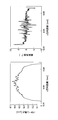
この結果、リフロー処理を行わない場合、図13の上段に示すように、インクパターンの断面形状は矩形状になった。また、図13の下段に示すように、印刷用絶縁膜インクの表面の傾斜角が限界傾斜角θの20℃を超えてしまう部分があった。これにより、条件1では、インクパターンの欠損が生じる可能性があることがわかる。
次に、条件2に基づき、有機溶媒にはアセトン又はテトラデカフルオロヘキサン(フロリナートTMFC-72)を用い、PDMSブランケットBk上の印刷用絶縁膜インクにリフロー処理を施した。このとき、アセトン又はフロリナートTMFC-72によってリフロー処理を行ったときの実験結果を図14に示す。ここで、アセトンとフロリナートTMFC-72の沸点は両方とも56℃である。
実験結果から印刷用絶縁膜インクと混和する有機溶媒を使わないとインクの表面にリフローが起こらないことが確認できた。図14の下段に示すように、有機溶媒の一つであるフロリナートTMFC-72は、印刷用絶縁膜インクと混和しないため、加熱時間を増やしても印刷用絶縁膜インクの表面がリフローされず、最大傾斜角は20°以上になっている。
他方、インクと混和する有機溶媒であって、その有機溶媒の沸点以上の温度で溶媒蒸気に曝露すれば、その曝露時間を増やすことでリフローが起こっていることがわかった。図14の上段に示すように、アセトンを使った場合、60℃以上に加熱されたアセトン飽和蒸気下で7秒リフローすれば、印刷用絶縁膜インクのパターンの断面形状の最大傾斜角を20°以下にすることができることがわかった。特に、アセトンを60℃~80℃の温度に加熱することが好ましい。
さらに、リフロー後のインクが、線幅の異なるパターンに対してどのような影響を受けるかについて調べた。スリットコーターでPDMSブランケットBk上に印刷用絶縁膜インクを塗布し、印刷装置100を使って線幅が20μm、30μm、40μm、50μm、60μm、80μm、100μmの7種類のパターンを形成した。
有機溶媒の種類はアセトンを用いた。印刷用絶縁膜インクを、60℃に加熱されたアセトン飽和蒸気雰囲気に7秒間さらし、パターンの色が受理(印刷版で不要なインクを取り除く)後の色に戻ってから、ガラス基板に転写し、段差計で測定した。その実験結果を図15及び図16に示す。
図15の結果から、パターンのピークの高さは、パターンの線幅によらず、変わらないことが確認できた。また、図16の結果から、各線幅のインクパターンの側壁角は最大でも8°程度で限界傾斜角θの20°よりも十分に小さいことが確認できた。図14~図16に示す結果から、リフロー処理を実行した場合、インクパターンの側壁角は異なる線幅のいずれのパターンにおいても最大で6°~8°程度であることがわかった。
最後に、ガラス基板上にインクパターンを転写した後に、インクパターンをアセトンの飽和蒸気圧の雰囲気に晒した場合、印刷用絶縁膜インクに適切なリフローが生じるかどうかを調べた。その際の条件としては、スリットコーターでブランケットBkに印刷用絶縁膜インクを塗布し、印刷版で線幅が100μmのパターンを形成した。100μmのインクパターンをガラス基板(紫外線による洗浄を行ったガラス)に転写し、その後60℃のアセトンの飽和蒸気雰囲気に10秒間曝露した。その後、パターンを段差計で測定した。測定結果を図17に示す。図17に示すように、基板上にインクパターンを転写した後に、インクパターンをアセトンの飽和蒸気圧の雰囲気に晒した場合であっても、印刷用絶縁膜インクはリフローされる。しかし、リフロー後のインクパターンの断面形状が、本実施形態にかかる印刷方法よりも多少粗れること、及び側壁角も多少大きいことがわかった。つまり、同条件で本実施形態にかかる印刷方法を実行した場合、つまり、有機溶媒の飽和蒸気圧の雰囲気に晒した後のインクパターンを基板に転写する本実施形態の印刷方法の場合、図18及び図19に示すように、明らかにインクに対するリフローの効果が高い。また、インク表面の側壁角が小さくかつバラツキがなく、インク表面が滑らかで凹凸が少ないことがわかる。
本実施形態についての上記検討結果によれば、インク材と混和する有機溶媒の飽和蒸気圧の雰囲気に曝露することでインク材をリフローさせパターンの側壁角を小さくすることができることが確認できた。本実施形態によれば、被印刷基板上を転写ローラ5が相対的に転動する際に転写ローラ5が常に接触する限界傾斜角θを算出し、被印刷基板上のインクの凹凸構造の側壁角を限界傾斜角θ以下に再構成する。これにより、転写ローラ5の表面が被印刷基板の凹凸表面に常に接触して相対的に転動するようになり、被印刷基板と転写ローラ5とが常に接触し、印刷パターンの欠落が生じることが防止され、高い解像性と寸法精度を保ちパターンを印刷できる。
以上に説明したように、本実施形態では、雰囲気制御手段400が付設され、一体的に形成された印刷装置100において、ブランケットBk上に形成されたパターンが、ブランケットBk上でリフローされた後、リフロー後のインク材を基板に転写する。これにより、パターン印刷の忠実性を高めることができる。
[有機溶媒]
有機溶媒は、ブランケットBkに塗布されたインクと混和が可能な以下に示す溶媒であれば、本実施形態にかかる印刷方法に適用できる。
有機溶媒は、ブランケットBkに塗布されたインクと混和が可能な以下に示す溶媒であれば、本実施形態にかかる印刷方法に適用できる。
絶縁インクに含まれるモノマー、オリゴマー、樹脂成分等の少なくとも一部に対し適度の溶解性を有し、熱処理またはエネルギー線等による架橋硬化前の印刷パターンを溶剤蒸気等でリフローできる溶剤であれば適用可能である。例えば、DIC製反転印刷絶縁インクを適用する場合、インクに含まれる樹脂成分であるポリビニルフェノール系樹脂し一定の溶解性を有する、例えば、ペンタン、ヘキサン、ヘプタン、オクタン、デカン、ドデカン、イソペンタン、イソヘキサン、イソオクタン、シクロヘキサン、メチルシクロヘキサン、シクロペンタン等の脂肪族炭化水素系有機溶媒、ベンゼン、トルエン、o-キシレン、m-キシレン、p-キシレン、エチルベンゼン、メシチレン、ナフタレン、シクロヘキシルベンゼン、ジエチルベンゼン等の芳香族炭化水素系溶剤、蟻酸メチル、蟻酸エチル、蟻酸プロピル、酢酸メチル、酢酸エチル、酢酸イソプロピル、酢酸n-プロピル、酢酸イソブチル、酢酸n-ブチル、プロピオン酸メチル、プロピオン酸エチル等のエステル系溶剤、メタノール、エタノール、プロパノール、イソプロパノール、sec-ブタノール、tert-ブタノール、シクロヘキサノール、α-テルピネオール等のアルコール系溶剤、アセトン、メチルエチルケトン、メチルイソブチルケトン、シクロヘキサノン、2-ヘキサノン、2-ヘプタノン、2-オクタノン、テトラヒドロフラン等のケトン系溶剤、エチレンカーボネート、プロピレンカーボネート等の炭酸エステル類、ジエチレングリコールエチルエーテル、ジエチレングリコールジエチルエーテル、プロピレングリコールモノメチルエーテル、プロピレングリコールモノエチルエーテル、プロピレングリコールモノプロピルエーテル、プロピレングリコールモノブチルエーテル、プロピレングリコールモノメチルエーテルアセテート、ジエチレングリコールメチルエーテルアセテート、ジエチレングリコールエチルエーテルアセテート、ジエチレングリコールプロピルエーテルアセテート、ジエチレングリコールイソプロピルエーテルアセテート、ジエチレングリコールブチルエーテルアセテート、ジエチレングリコール-t-ブチルエーテルアセテート、トリエチレングリコールメチルエーテルアセテート、トリエチレングリコールエチルエーテルアセテート、トリエチレングリコールプロピルエーテルアセテート、トリエチレングリコールイソプロピルエーテルアセテート、トリエチレングリコールブチルエーテルアセテート、トリエチレングリコール-t-ブチルエーテルアセテート、ジプロピレングリコールジメチルエーテル、ジプロピレングリコールモノブチルエーテル等のアルキレングリコール系溶剤、ジエチルエーテル、ジプロピルエーテル、ジイソプロピルエーテル、ジブチルエーテル、ジヘキシルエーテル、エチルビニルエーテル、ブチルビニルエーテル、アニソール、ブチルフェニルエーテル、ペンチルフェニルエーテル、メトキシトルエン、ベンジルエチルエーテル、ジフェニルエーテル、ジベンジルエーテル、ジオキサン、フラン、テトラヒドロフラン等のエーテル系溶剤、N、N-ジメチルホルムアミド、N、N-ジメチルアセタミド、N-メチルピロリドン等のアミド系溶媒等々があるが、特に限定されるものではない。また、これらは単独または二種類以上を併用してもよい。もちろんこれら各種溶剤で、絶縁パターン形成の被印刷基板、他の機能性パターンに悪影響を与えない溶剤を適宜選択できる。
反転印刷ナノAg(金属)インクパターンのリフローについて
熱焼成、Xeフラッシュ、IR等による導電体への焼結前の印刷パターンをリフローできる各種溶剤を使用できる。Ag、Cu等のナノ粒子を適用したインクを適用する場合、これらナノ金属粒子の分散液として適用できる各種溶剤好適に適用できる。
例えば、比較的極性の高い分散溶媒を適用しているDIC製ナノAgインク(RAGTシリース゛RAGT15~28)の場合、水、メタノール、エタノール、ブチルアルコール、メトキシブタノール、ターシャリーブタノール等のアルコール類;エチレングリコール、プロピレングリコール、ジエチレングリコール、グリセリン等の多価アルコール類;酢酸エチル、酢酸メチル、酢酸イソブチル、乳酸エチル等のエステル類およびプロピレンカーボネート等の炭酸エステル類;イソプロピルエーテル、メチルターシャリーブチルエーテル、テトラヒドロフラン等のエーテル類;アセトン、メチルエチルケトン、メチルブチルケトン、メチルイソブチルケトン、シクロヘキサノン、ジアセトンアルコール等のケトン類;メチルセロソルブ、セロソルブ、ブチルセロソルブ、ジエチレングリコールモノメチルエーテル、ジプロピレングリコールモノメチルエーテル、プロピレングリコールモノメチルエーテル、プロピレングリコールモノエチルエーテル等のグリコールエーテル類;エチレングリコールモノメチルエーテルアセテート等のグリコールアセテート類;メチルトリグライム、エチルモノグライム等のグリコールジエーテル類;シクロヘキサノン、メチルシクロヘキサノン、シクロヘキサノール、メチルシクロヘキサノール等の脂環式炭化水素類;ノルマルへキサン等の脂肪族炭化水素類;トルエン、キシレン等の芳香族炭化水素類;クロルベンゼン、オルトジクロロベンゼン等の塩化芳香族炭化水素類;ジクロロメタン、クロロホルム、四塩化炭素、ジクロロエチレン、トリクロロエチレン等の塩化脂肪族炭化水素類から選ばれる単独又は混合溶剤が適宜適用できる。
反転印刷ナノAg(金属)インクパターンのリフローについて
熱焼成、Xeフラッシュ、IR等による導電体への焼結前の印刷パターンをリフローできる各種溶剤を使用できる。Ag、Cu等のナノ粒子を適用したインクを適用する場合、これらナノ金属粒子の分散液として適用できる各種溶剤好適に適用できる。
例えば、比較的極性の高い分散溶媒を適用しているDIC製ナノAgインク(RAGTシリース゛RAGT15~28)の場合、水、メタノール、エタノール、ブチルアルコール、メトキシブタノール、ターシャリーブタノール等のアルコール類;エチレングリコール、プロピレングリコール、ジエチレングリコール、グリセリン等の多価アルコール類;酢酸エチル、酢酸メチル、酢酸イソブチル、乳酸エチル等のエステル類およびプロピレンカーボネート等の炭酸エステル類;イソプロピルエーテル、メチルターシャリーブチルエーテル、テトラヒドロフラン等のエーテル類;アセトン、メチルエチルケトン、メチルブチルケトン、メチルイソブチルケトン、シクロヘキサノン、ジアセトンアルコール等のケトン類;メチルセロソルブ、セロソルブ、ブチルセロソルブ、ジエチレングリコールモノメチルエーテル、ジプロピレングリコールモノメチルエーテル、プロピレングリコールモノメチルエーテル、プロピレングリコールモノエチルエーテル等のグリコールエーテル類;エチレングリコールモノメチルエーテルアセテート等のグリコールアセテート類;メチルトリグライム、エチルモノグライム等のグリコールジエーテル類;シクロヘキサノン、メチルシクロヘキサノン、シクロヘキサノール、メチルシクロヘキサノール等の脂環式炭化水素類;ノルマルへキサン等の脂肪族炭化水素類;トルエン、キシレン等の芳香族炭化水素類;クロルベンゼン、オルトジクロロベンゼン等の塩化芳香族炭化水素類;ジクロロメタン、クロロホルム、四塩化炭素、ジクロロエチレン、トリクロロエチレン等の塩化脂肪族炭化水素類から選ばれる単独又は混合溶剤が適宜適用できる。
以上、転写印刷装置及び転写印刷方法を上記実施形態により説明したが、本発明にかかる転写印刷装置及び転写印刷方法は上記実施形態に限定されるものではなく、本発明の範囲内で種々の変形及び改良が可能である。上記複数の実施形態に記載された事項は、矛盾しない範囲で組み合わせることができる。例えば以下のような場合についても十分な効果が得られる。
リフローを実施する前に、結露防止のためにブランケットBkまたは基板を数秒非溶媒雰囲気下で加熱してもよい。リフローに用いる溶媒は、インクと混和すればよく、アセトンでなくてもよい。リフロー工程において、インクが下地膜と固着することをさけるため、溶媒の沸点は低いことが望ましい。
リフローを行う直前のインクは、リフローに使用する溶媒と接触することによって、再度溶解または再度分散可能な状態にあればよく、一般的に生乾きとよばれる状態(体積固形分率が30%~80%)にあることが望ましい。
本国際出願は、2016年4月13日に出願された日本国特許出願2016-080292号に基づく優先権を主張するものであり、その全内容を本国際出願に援用する。
5 転写ローラ
100 印刷装置
200 制御装置
300 制御I/F機構
400 雰囲気制御手段
401 動入管
401a 導入口
402,403 排気管
402a、403a 排気口
410 筐体
410a 凹み部
501 湿度センサ
502 温度センサ
500,510、520,530 ヒータ
600 蒸気発生器
520、630 配管
θ 限界傾斜角
Bk ブランケット
Ik インク
U バッファ空間
OL 有機溶媒
Pr 印刷版
Pw ワーク板
100 印刷装置
200 制御装置
300 制御I/F機構
400 雰囲気制御手段
401 動入管
401a 導入口
402,403 排気管
402a、403a 排気口
410 筐体
410a 凹み部
501 湿度センサ
502 温度センサ
500,510、520,530 ヒータ
600 蒸気発生器
520、630 配管
θ 限界傾斜角
Bk ブランケット
Ik インク
U バッファ空間
OL 有機溶媒
Pr 印刷版
Pw ワーク板
Claims (11)
- 転写ローラの上のブランケットに塗布したインクのパターンを被印刷基板に印刷する転写印刷装置であって、
前記転写ローラに近接した位置に設けられ、所定の有機溶媒を導入し、前記ブランケットに塗布したインクに向けて供給する導入口と、前記有機溶媒を排気する排気口とを有する雰囲気制御手段を有する、
転写印刷装置。 - 前記雰囲気制御手段は、前記有機溶媒の蒸気雰囲気を前記インクに向けて供給する、
請求項1に記載の転写印刷装置。 - 前記雰囲気制御手段は、前記導入口に接続され、前記有機溶媒を蒸気にする蒸気機構を有する、
請求項2に記載の転写印刷装置。 - 前記雰囲気制御手段は、前記有機溶媒の温度制御を行う加熱手段を有する、
請求項1に記載の転写印刷装置。 - 前記加熱手段は、前記有機溶媒の飽和蒸気圧の雰囲気を形成する、
請求項4に記載の転写印刷装置。 - 前記加熱手段は、前記雰囲気制御手段、前記雰囲気制御手段に有機溶媒を供給する経路、前記転写ローラ及び蒸気発生器の少なくともいずれかの位置に設置される、
請求項4に記載の転写印刷装置。 - 前記雰囲気制御手段は、前記導入口から導入した有機溶媒を前記排気口から排気する差動排気機構を有する、
請求項1に記載の転写印刷装置。 - 前記転写ローラを回転させて、前記雰囲気制御手段から供給される前記有機溶媒の蒸気雰囲気により前記ブランケットに塗布したインクをリフローさせた後、更に前記転写ローラを回転させて前記インクのパターンを被印刷基板に転写する、
請求項2に記載の転写印刷装置。 - 前記ブランケットに塗布したインクの表面が、前記転写ローラが前記被印刷基板と接触を保つことが可能な限界傾斜角以下になるように、前記転写ローラの回転速度を制御して前記ブランケットに塗布したインクをリフローする時間を制御する、
請求項8に記載の転写印刷装置。 - 前記有機溶媒は、前記ブランケットに塗布されたインクと混和が可能な所定の溶媒である、
請求項1に記載の転写印刷装置。 - 転写ローラの上のブランケットにインクを塗布する塗布工程と、前記ブランケットに塗布されたインクにパターンを形成するパターン形成工程と、前記形成したインクのパターンを被印刷基板に転写する転写工程と、を有する転写印刷方法であって、
前記転写工程は、
前記転写ローラを回転させて、前記転写ローラに近接した位置に設けられ、所定の有機溶媒を導入し、前記ブランケットに塗布したインクに向けて供給する導入口と、前記有機溶媒を排気する排気口とを有する雰囲気制御手段から供給される前記有機溶媒の蒸気雰囲気により前記ブランケットに塗布したインクをリフローさせた後、更に前記転写ローラを回転させて前記インクのパターンを被印刷基板に転写する、転写印刷方法。
Priority Applications (1)
| Application Number | Priority Date | Filing Date | Title |
|---|---|---|---|
| JP2018511965A JP6741258B2 (ja) | 2016-04-13 | 2017-03-31 | 転写印刷装置及び転写印刷方法 |
Applications Claiming Priority (2)
| Application Number | Priority Date | Filing Date | Title |
|---|---|---|---|
| JP2016080292 | 2016-04-13 | ||
| JP2016-080292 | 2016-04-13 |
Publications (1)
| Publication Number | Publication Date |
|---|---|
| WO2017179446A1 true WO2017179446A1 (ja) | 2017-10-19 |
Family
ID=60042557
Family Applications (1)
| Application Number | Title | Priority Date | Filing Date |
|---|---|---|---|
| PCT/JP2017/013552 Ceased WO2017179446A1 (ja) | 2016-04-13 | 2017-03-31 | 転写印刷装置及び転写印刷方法 |
Country Status (2)
| Country | Link |
|---|---|
| JP (1) | JP6741258B2 (ja) |
| WO (1) | WO2017179446A1 (ja) |
Families Citing this family (1)
| Publication number | Priority date | Publication date | Assignee | Title |
|---|---|---|---|---|
| CN116749667B (zh) * | 2022-03-04 | 2025-12-19 | 广东聚华印刷显示技术有限公司 | 喷墨打印方法以及喷墨打印装置 |
Citations (6)
| Publication number | Priority date | Publication date | Assignee | Title |
|---|---|---|---|---|
| JPS63116851A (ja) * | 1986-11-05 | 1988-05-21 | Matsushita Electric Ind Co Ltd | フレキソ印刷機 |
| JP2001502253A (ja) * | 1996-03-13 | 2001-02-20 | ハイデルベルガー ドルツクマシーネン アクチエンゲゼルシャフト | 様々な種類のインキを使用する印刷ユニット |
| JP2006047476A (ja) * | 2004-08-02 | 2006-02-16 | Nec Kagoshima Ltd | Tftアレイパターン形成方法 |
| JP2008207485A (ja) * | 2007-02-27 | 2008-09-11 | Mitsubishi Heavy Ind Ltd | 印刷機及び印刷方法 |
| JP2010083130A (ja) * | 2008-09-03 | 2010-04-15 | Toppan Printing Co Ltd | 凸版印刷装置 |
| US20110155004A1 (en) * | 2009-12-30 | 2011-06-30 | Nam Seung-Hee | Device and method for forming thin film pattern |
Family Cites Families (1)
| Publication number | Priority date | Publication date | Assignee | Title |
|---|---|---|---|---|
| JP6655844B2 (ja) * | 2014-03-28 | 2020-02-26 | 国立研究開発法人産業技術総合研究所 | 均一膜厚かつ矩形断面を有するパターン膜形成方法、形成装置 |
-
2017
- 2017-03-31 WO PCT/JP2017/013552 patent/WO2017179446A1/ja not_active Ceased
- 2017-03-31 JP JP2018511965A patent/JP6741258B2/ja active Active
Patent Citations (6)
| Publication number | Priority date | Publication date | Assignee | Title |
|---|---|---|---|---|
| JPS63116851A (ja) * | 1986-11-05 | 1988-05-21 | Matsushita Electric Ind Co Ltd | フレキソ印刷機 |
| JP2001502253A (ja) * | 1996-03-13 | 2001-02-20 | ハイデルベルガー ドルツクマシーネン アクチエンゲゼルシャフト | 様々な種類のインキを使用する印刷ユニット |
| JP2006047476A (ja) * | 2004-08-02 | 2006-02-16 | Nec Kagoshima Ltd | Tftアレイパターン形成方法 |
| JP2008207485A (ja) * | 2007-02-27 | 2008-09-11 | Mitsubishi Heavy Ind Ltd | 印刷機及び印刷方法 |
| JP2010083130A (ja) * | 2008-09-03 | 2010-04-15 | Toppan Printing Co Ltd | 凸版印刷装置 |
| US20110155004A1 (en) * | 2009-12-30 | 2011-06-30 | Nam Seung-Hee | Device and method for forming thin film pattern |
Also Published As
| Publication number | Publication date |
|---|---|
| JP6741258B2 (ja) | 2020-08-19 |
| JPWO2017179446A1 (ja) | 2019-05-09 |
Similar Documents
| Publication | Publication Date | Title |
|---|---|---|
| KR102390822B1 (ko) | Euv 리소그래피용 pecvd 막 | |
| US8673086B2 (en) | Method and device for cleaning a substrate and storage medium | |
| KR101207872B1 (ko) | 기판 처리 방법, 이 기판 처리 방법을 실행시키기 위한 프로그램을 기록한 기록 매체 및 기판 처리 장치 | |
| TWI550365B (zh) | 使用後處理方法以加速超紫外線微影之方法 | |
| US8420304B2 (en) | Resist coating and developing apparatus, resist coating and developing method, resist-film processing apparatus, and resist-film processing method | |
| JP4393268B2 (ja) | 微細構造体の乾燥方法 | |
| US20160326386A1 (en) | Method and apparatus for aerosol-based three-dimensional (3d) printing of flexible graphene electronic devices | |
| JP6644881B2 (ja) | 高アスペクト比フィーチャ向けの乾燥プロセス | |
| JP6007155B2 (ja) | 現像処理方法、プログラム、コンピュータ記憶媒体及び現像処理装置 | |
| TWI631611B (zh) | 高深寬比結構之無坍陷乾燥方法 | |
| Leppäniemi et al. | Reverse‐offset printing of metal‐nitrate‐based metal oxide semiconductor ink for flexible TFTs | |
| JPWO2017164031A1 (ja) | 印刷版、印刷版の製造方法および印刷方法 | |
| Yu et al. | Rapid sintering of copper nano ink using a laser in air | |
| KR20140132274A (ko) | 레지스트 조성물의 제조 방법 | |
| JP6741258B2 (ja) | 転写印刷装置及び転写印刷方法 | |
| WO2024024919A1 (ja) | 基板処理方法及び基板処理システム | |
| Sung et al. | Fabrication of high-resolution conductive lines by combining inkjet printing with soft lithography | |
| KR102153767B1 (ko) | 기판 처리 방법, 컴퓨터 기억 매체 및 기판 처리 시스템 | |
| WO2015141604A1 (en) | Imprint apparatus and method of manufacturing article | |
| JP2011165691A (ja) | 減圧乾燥方法及び減圧乾燥装置 | |
| US9552987B2 (en) | Substrate processing method, substrate processing apparatus, and storage medium | |
| TWI660434B (zh) | 基板處理方法及基板處理裝置 | |
| JP5168029B2 (ja) | 印刷装置及び印刷物の製造方法 | |
| JP2008210930A (ja) | 半導体装置の製造方法 | |
| JP2024522384A (ja) | 基板上に高解像度パターンを生成するための方法およびシステム |
Legal Events
| Date | Code | Title | Description |
|---|---|---|---|
| ENP | Entry into the national phase |
Ref document number: 2018511965 Country of ref document: JP Kind code of ref document: A |
|
| NENP | Non-entry into the national phase |
Ref country code: DE |
|
| 121 | Ep: the epo has been informed by wipo that ep was designated in this application |
Ref document number: 17782264 Country of ref document: EP Kind code of ref document: A1 |
|
| 122 | Ep: pct application non-entry in european phase |
Ref document number: 17782264 Country of ref document: EP Kind code of ref document: A1 |