WO2017179324A1 - Système de refroidissement de véhicule - Google Patents
Système de refroidissement de véhicule Download PDFInfo
- Publication number
- WO2017179324A1 WO2017179324A1 PCT/JP2017/007586 JP2017007586W WO2017179324A1 WO 2017179324 A1 WO2017179324 A1 WO 2017179324A1 JP 2017007586 W JP2017007586 W JP 2017007586W WO 2017179324 A1 WO2017179324 A1 WO 2017179324A1
- Authority
- WO
- WIPO (PCT)
- Prior art keywords
- radiator
- low
- cooling water
- temperature
- temperature radiator
- Prior art date
Links
Images


Classifications
-
- B—PERFORMING OPERATIONS; TRANSPORTING
- B60—VEHICLES IN GENERAL
- B60K—ARRANGEMENT OR MOUNTING OF PROPULSION UNITS OR OF TRANSMISSIONS IN VEHICLES; ARRANGEMENT OR MOUNTING OF PLURAL DIVERSE PRIME-MOVERS IN VEHICLES; AUXILIARY DRIVES FOR VEHICLES; INSTRUMENTATION OR DASHBOARDS FOR VEHICLES; ARRANGEMENTS IN CONNECTION WITH COOLING, AIR INTAKE, GAS EXHAUST OR FUEL SUPPLY OF PROPULSION UNITS IN VEHICLES
- B60K11/00—Arrangement in connection with cooling of propulsion units
- B60K11/02—Arrangement in connection with cooling of propulsion units with liquid cooling
- B60K11/04—Arrangement or mounting of radiators, radiator shutters, or radiator blinds
-
- F—MECHANICAL ENGINEERING; LIGHTING; HEATING; WEAPONS; BLASTING
- F01—MACHINES OR ENGINES IN GENERAL; ENGINE PLANTS IN GENERAL; STEAM ENGINES
- F01P—COOLING OF MACHINES OR ENGINES IN GENERAL; COOLING OF INTERNAL-COMBUSTION ENGINES
- F01P3/00—Liquid cooling
- F01P3/18—Arrangements or mounting of liquid-to-air heat-exchangers
-
- F—MECHANICAL ENGINEERING; LIGHTING; HEATING; WEAPONS; BLASTING
- F01—MACHINES OR ENGINES IN GENERAL; ENGINE PLANTS IN GENERAL; STEAM ENGINES
- F01P—COOLING OF MACHINES OR ENGINES IN GENERAL; COOLING OF INTERNAL-COMBUSTION ENGINES
- F01P5/00—Pumping cooling-air or liquid coolants
- F01P5/02—Pumping cooling-air; Arrangements of cooling-air pumps, e.g. fans or blowers
- F01P5/06—Guiding or ducting air to, or from, ducted fans
-
- F—MECHANICAL ENGINEERING; LIGHTING; HEATING; WEAPONS; BLASTING
- F01—MACHINES OR ENGINES IN GENERAL; ENGINE PLANTS IN GENERAL; STEAM ENGINES
- F01P—COOLING OF MACHINES OR ENGINES IN GENERAL; COOLING OF INTERNAL-COMBUSTION ENGINES
- F01P7/00—Controlling of coolant flow
- F01P7/14—Controlling of coolant flow the coolant being liquid
- F01P7/16—Controlling of coolant flow the coolant being liquid by thermostatic control
Definitions
- the present disclosure relates to a cooling system that cools a device to be cooled of a vehicle.
- Patent Document 1 describes a thermal energy control system including a high water temperature cooling cycle and a low water temperature cooling cycle.
- This prior art includes a high water temperature radiator, a low water temperature radiator, a circulation pump, and a flow path switching control valve.
- Each radiator has a first passage and a second passage.
- cooling water is circulated by a circulation pump, and heat is exchanged by cooling water and cooling air flowing through the first passage and the second passage of the low water temperature radiator.
- the low-temperature radiator is disposed in front of the engine room of the vehicle.
- an upper grill and a lower grill are provided at the front of the vehicle body, and outside air is introduced into the radiator and other heat exchangers from the upper grill and the lower grill, and flows into the engine room.
- the upper grill is disposed near the front end of the engine hood.
- the lower grill is formed integrally with the front bumper below the upper grill.
- the aerodynamic performance (for example, “Cd value”) can be improved by restricting the inflow of air into the engine room by closing the shut mechanism, so that the running resistance of the vehicle is reduced. This can reduce fuel consumption.
- a cooling system for a vehicle includes a first radiator and a second radiator that exchange heat between the heat-receiving device) and the outside air introduced from the opening of the vehicle and the heat medium. And an opening area adjustment unit that adjusts the opening area of the opening, A flow rate ratio adjusting unit that adjusts a flow rate ratio between the heat medium flowing through the first radiator and the heat medium flowing through the second radiator; and a control device that controls the operation of the flow rate adjusting unit according to the operating state of the opening area adjusting unit; Is provided.
- the flow rate of the heat medium to the first radiator and the second radiator can be changed according to the state of introduction of the outside air to the first radiator and the second radiator. Therefore, it is possible to efficiently flow the heat medium to the first radiator and the second radiator.
- the control device when the opening area adjustment unit is operating so that the introduction of outside air to one of the first radiator and the second radiator is suppressed, the control device has a flow rate of the heat medium flowing through the one radiator.
- the operation of the flow rate ratio adjusting unit is controlled so as to decrease.
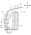
- FIG. 1 is an overall configuration diagram of a vehicle cooling system according to an embodiment. It is sectional drawing of the vehicle by which the cooling system for vehicles in one Embodiment is mounted, and has shown the state by which the shutter mechanism was opened. It is a front view of the 1st radiator and the 2nd radiator in one embodiment. It is a front view of the 1st radiator and the 2nd radiator in the modification of one embodiment. It is a front view of the 1st radiator and the 2nd radiator in the modification of one embodiment. It is sectional drawing of the tube in one Embodiment. It is sectional drawing of the tube in the modification of one Embodiment.
- FIG. 1 The up and down arrows in FIG. 1 indicate the up and down directions in a vehicle on which the vehicle cooling system is mounted.
- the first low-temperature radiator 11, the second low-temperature radiator 12, the engine cooling radiator 13, and the blower 14 are arranged in the front part of the engine room 15 of the vehicle.
- the first low-temperature radiator 11, the second low-temperature radiator 12, the engine cooling radiator 13, and the blower 14 constitute an integrated assembly structure. That is, the first low-temperature radiator 11, the second low-temperature radiator 12, the engine cooling radiator 13 and the blower 14 constitute a cooling module.
- the first low-temperature radiator 11, the second low-temperature radiator 12, and the engine cooling radiator 13 are incorporated in a common front end panel 16.
- the front end panel 16 supports the periphery of the first low-temperature radiator 11, the second low-temperature radiator, and the engine cooling radiator 13, and the air flow passing through the first low-temperature radiator 11, the second low-temperature radiator 12, and the engine cooling radiator 13. It is a member which guides.
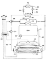
- the first low-temperature radiator 11 and the second low-temperature radiator 12 are heat exchangers that exchange heat between the cooling water in the low-temperature cooling water circuit 30 shown in FIG. 2 and air outside the vehicle compartment (hereinafter referred to as outside air).
- the engine cooling radiator 13 is a heat exchanger that exchanges heat between the coolant of the engine coolant circuit 40 shown in FIG. 2 and the outside air.
- the engine cooling radiator 13 is arranged on the downstream side of the outside air flow of the first low-temperature radiator 11 and the second low-temperature radiator 12. That is, the engine cooling radiator 13 is disposed on the vehicle rear side of the first low-temperature radiator 11 and the second low-temperature radiator 12.
- the low-temperature cooling water circuit 30 and the engine cooling water circuit 40 are cooling water circulation circuits through which cooling water circulates.
- the low-temperature cooling water circuit 30 and the engine cooling water circuit 40 are independent cooling water circuits.
- Cooling water is a fluid as a heat medium.
- the cooling water is an ethylene glycol antifreeze (so-called LLC).
- the blower 14 is a blower that blows air toward the first low-temperature radiator 11, the second low-temperature radiator, and the engine cooling radiator 13.
- the blower 14 is an electric blower that drives an axial fan with an electric motor.
- Bumper lean force 17 and bumper cover 18 are disposed at the front end of engine room 15.
- the bumper lean force 17 is a beam-like member that extends in the vehicle width direction at the front end portion of the vehicle and absorbs a collision force from the vehicle front side.
- the bumper cover 18 is disposed on the front side of the bumper lean force 17.
- the bumper cover 18 is a resin component that covers the front side of the bumper reinforcement 17.
- the upper surface opening of the engine room 15 is blocked by an engine hood 19.
- An under cover 20 is disposed below the engine room 15.
- An upper opening 21 is provided above the bumper lean force 17.
- a lower opening 22 is provided below the bumper lean force 17.
- the upper side opening 21 and the lower side opening 22 are outside air introduction ports for introducing outside air into the first low temperature radiator 11, the second low temperature radiator and the engine cooling radiator 13 in the engine room 15.
- the first low-temperature radiator 11 is disposed in the engine room 15 at a position facing the upper opening 21.
- the second low-temperature radiator 12 is disposed in the engine room 15 at a position facing the lower opening 22.
- a shutter mechanism 23 is disposed in the lower opening 22.
- the shutter mechanism 23 is an introduction air volume adjustment unit that adjusts the air volume of air introduced from the lower opening 22 by opening and closing the lower opening 22.
- the shutter mechanism 23 is an opening area adjustment unit that adjusts the opening area of the lower opening 22. In other words, the shutter mechanism 23 adjusts the opening area of a portion of the upper opening 21 and the lower opening 22 that faces the second low-temperature radiator 12.
- the shutter mechanism 23 has a plurality of plate doors.
- the shutter mechanism 23 is rotationally displaced by being driven by the electric actuator 24 shown in FIG.
- the electric actuator 24 rotates and displaces a plurality of plate doors, the lower opening 22 is opened and closed.
- FIG. 1 shows a state in which the shutter mechanism 23 closes the lower opening 22.
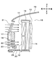
- FIG. 3 shows a state in which the shutter mechanism 23 opens the lower opening 22.
- the shutter mechanism 23 closes the lower opening 22 when traveling at a high speed (for example, when traveling at 80 km / h or more). Thereby, the aerodynamic performance (for example, “Cd value”) at the time of high speed traveling is improved.
- a high speed for example, when traveling at 80 km / h or more.
- the shutter mechanism 23 opens the lower opening 22 except when traveling at high speeds and at low outside temperatures.
- outside air is introduced from the lower opening 22, so that the outside air flows to the second low-temperature radiator 12.
- a bumper lean force 25 is disposed in the vicinity of the under cover 20.
- the first low-temperature radiator 11 and the second low-temperature radiator 12 are arranged in parallel with each other in the cooling water flow of the low-temperature cooling water circuit 30.
- the first low-temperature radiator 11 is a first radiator of the low-temperature cooling water circuit 30.
- the second low-temperature radiator 12 is a second radiator of the low-temperature cooling water circuit 30.
- a low-temperature cooling water pump 31 In the low-temperature cooling water circuit 30, a low-temperature cooling water pump 31, a turbocharger 32, an intercooler 33, a refrigerant radiator 34, a first switching valve 35, and a second switching valve 36 are arranged.
- the low-temperature cooling water pump 31 is an electric pump that sucks and discharges cooling water from the low-temperature cooling water circuit 30.
- the turbocharger 32, the intercooler 33, and the refrigerant radiator 34 are devices to be cooled that are cooled by the cooling water of the low-temperature cooling water circuit 30.
- the turbocharger 32 is a supercharger that supercharges intake air from the engine 41.
- the intercooler 33 is an intake air cooler that cools the supercharged intake air by exchanging heat between the supercharged intake air that has been compressed by the turbocharger 32 and has reached a high temperature and the cooling water.
- turbocharger 32 and the intercooler 33 are arranged in parallel with each other in the cooling water flow of the low-temperature cooling water circuit 30. Further, the turbocharger 32 and the intercooler 33 are arranged in parallel with the refrigerant radiator 34 in the cooling water flow of the low-temperature cooling water circuit 30.
- the refrigerant radiator 34 is a heat exchanger that cools the refrigerant by exchanging heat between the high-temperature and high-pressure refrigerant of the refrigeration cycle 50 and the cooling water of the low-temperature cooling water circuit 30.
- the refrigeration cycle 50 includes a compressor 51, a refrigerant radiator 34, an expansion valve 52, and an evaporator 53.
- the compressor 51 sucks and compresses the low-pressure refrigerant of the refrigeration cycle 50 and discharges the high-pressure refrigerant.
- the refrigerant radiator 34 cools the high-pressure refrigerant by exchanging heat between the high-pressure refrigerant discharged from the compressor 51 and the cooling water in the low-temperature cooling water circuit 30.
- the expansion valve 52 is a decompression unit that decompresses and expands the high-pressure refrigerant cooled by the refrigerant radiator 34.
- the evaporator 53 is a heat exchanger for air conditioning that cools the air blown into the vehicle interior by exchanging heat between the low-pressure refrigerant decompressed by the expansion valve 52 and the air blown into the vehicle interior.
- the first switching valve 35 is a flow rate adjustment unit that adjusts the flow rate ratio between the cooling water flowing through the first low-temperature radiator 11 and the cooling water flowing through the second low-temperature radiator 12.
- the first switching valve 35 is disposed at a branch portion between the cooling water flow path on the first low temperature radiator 11 side and the cooling water flow path on the second low temperature radiator 12 side.
- the first switching valve 35 is an electromagnetic valve that opens and closes the cooling water flow path on the second low-temperature radiator 12 side.
- the first switching valve 35 opens the cooling water flow path on the second low-temperature radiator 12 side, the cooling water flows through both the first low-temperature radiator 11 and the second low-temperature radiator 12.
- the first switching valve 35 closes the cooling water flow path on the second low temperature radiator 12 side, the cooling water flows through the first low temperature radiator 11 and the cooling water does not flow through the second low temperature radiator 12.
- the second switching valve 36 is a flow rate adjustment unit that adjusts the flow rate of the cooling water flowing through the turbocharger 32 and the intercooler 33 and the cooling water flowing through the refrigerant radiator 34.
- the second switching valve 36 is disposed at a branch portion between the cooling water passage on the turbocharger 32 and the intercooler 33 side and the cooling water passage on the refrigerant radiator 34 side.
- the second switching valve 36 is an electromagnetic valve that opens and closes the cooling water flow path on the turbocharger 32 and intercooler 33 side.
- the second switching valve 36 opens the cooling water flow path on the turbocharger 32 and intercooler 33 side, the cooling water flows to the turbocharger 32, the intercooler 33 and the refrigerant radiator 34.
- the second switching valve 36 closes the cooling water flow path on the turbocharger 32 and the intercooler 33 side, the cooling water flows to the refrigerant radiator 34 and the cooling water does not flow to the turbocharger 32 and the intercooler 33.
- the engine coolant pump 42 is a pump that sucks and discharges coolant from the engine coolant circuit 40.
- the engine coolant pump 42 is a belt-driven pump that is driven by transmitting the driving force of the engine 41 through the belt.
- the engine coolant pump 42 may be an electric pump.
- the operation of the electric actuator 24 that drives the shutter mechanism 23, the low-temperature cooling water pump 31, the first switching valve 35, the second switching valve 36, and the blower 14 is controlled by a control signal output from the control device 60.
- the control device 60 is composed of a well-known microcomputer including a CPU, ROM, RAM and the like and its peripheral circuits, performs various calculations and processing based on a control program stored in the ROM, and is connected to the output side. Control the operation of the equipment.
- the control device 60 is a control unit that controls the operation of various control devices constituting the vehicle cooling system.
- the control device 60 is activated when power is supplied from a battery (not shown) when the occupant turns on an ignition switch of the vehicle.
- the electric actuator 24 for driving the shutter mechanism 23, the low-temperature cooling water pump 31, the first switching valve 35, the second switching valve 36, and the engine cooling water pump 42 are connected to the output side of the control device 60.
- a sensor group such as a vehicle speed sensor 61, an outside air temperature sensor 62, an intake air temperature sensor 63, and a refrigerant pressure sensor 64 is connected to the input side of the control device 60.
- the vehicle speed sensor 61 is a travel speed detector that detects the travel speed of the vehicle.
- the outside air temperature sensor 62 is an outside air temperature detecting unit that detects an outside temperature (that is, outside air temperature) Tam.
- the intake sensor 63 is an intake air temperature detection unit that detects the temperature of intake air flowing into the intercooler 33.
- the intake sensor 63 may be an intake pressure detector that detects the pressure of intake air flowing into the intercooler 33.
- the refrigerant pressure sensor 64 is a refrigerant pressure detector that detects the pressure of a refrigeration cycle (not shown). For example, the refrigerant pressure sensor 64 detects the pressure of the refrigerant discharged from the compressor 51 of the refrigeration cycle 50 and flowing into the refrigerant radiator 34.
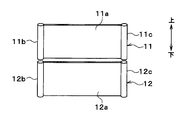
- the first low-temperature radiator 11 and the second low-temperature radiator 12 are separated from each other.
- the first low-temperature radiator 11 and the second low-temperature radiator 12 have the same front area.
- the first low-temperature radiator 11 and the second low-temperature radiator 12 may be integrated with each other.
- the first low-temperature radiator 11 and the second low-temperature radiator 12 may have different front areas.
- the front area of the first low-temperature radiator 11 is larger than the front area of the second low-temperature radiator 12, but the front area of the second low-temperature radiator 12 is larger than the front area of the first low-temperature radiator 11. It may be bigger.
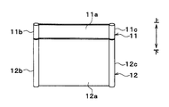
- the first low-temperature radiator 11 and the second low-temperature radiator 12 have core portions 11a and 12a and tanks 11b, 11c, 12b, and 12c, respectively.
- Core part 11a, 12a is a heat exchange part which heat-exchanges cooling water and air.
- the core parts 11a and 12a are formed in a substantially rectangular shape.
- the core parts 11a and 12a have many tubes and fins.
- the tube is a pipe through which cooling water flows. Many tubes are arranged in parallel to each other.
- the fin is joined to the flat surface of the tube.
- the fin is a heat exchange promoting member that increases the heat transfer area and promotes heat exchange between the refrigerant and the air.
- the fin is a corrugated fin formed in a wave shape.
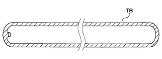
- the tube TB is a flat tube formed in a flat shape.
- the tube is arrange
- the tanks 11b, 11c, 12b, and 12c are joined to both ends of the tube TB.
- the tanks 11b, 11c, 12b, and 12c distribute and collect the cooling water with respect to the multiple tubes TB.
- the tube TB is a flat tube.
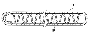
- the tube may be an inner fin tube having an inner fin IF.
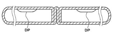
- the tube may be a dimple tube in which a dimple DP is formed.
- the cooling water flows from the one tank 11b, 11c, 12b, and 12c side to the other tank 11b, 11c, 12b, It flows in one direction toward the 12c side.
- the cooling water is directed from one tank 11b, 11c, 12b, 12c side to the other tank side.
- the other tank 11b, 11c, 12b, 12c may make a U-turn and flow toward the one tank 11b, 11c, 12b, 12c.
- the cooling water flows in a U-turn in the core portions 11a and 12a of the first low-temperature radiator 11, and the cooling water flows in one direction in the core portions 11a and 12a of the second low-temperature radiator 12. May be.
- the performance characteristics of the first low-temperature radiator 11 and the second low-temperature radiator 12 are different from each other. Specifically, when the wind speed of the inflowing outside air is in a high wind speed range, the first low-temperature radiator 11 and the first low-temperature radiator 11 and the second low-temperature radiator 12 have a heat exchange amount larger than that of the second low-temperature radiator 12. Two low-temperature radiators 12 are formed.
- the high wind speed region refers to the wind speed region of the outside air that flows into the first low-temperature radiator 11 (for example, about 80 km) when the shutter mechanism 23 closes the lower opening 22 and travels at a high speed (for example, when traveling at 80 km / h or more). / H or more).
- the first low-temperature radiator 11 and the second low-temperature radiator 12 so that the heat exchange amount of the second low-temperature radiator 12 is larger than the heat exchange amount of the first low-temperature radiator 11. Is formed.
- the contribution of the air side to the cooling is larger than that of the second low-temperature radiator 12, and in the second low-temperature radiator 12, the contribution of the cooling water side to the cooling is the first low-temperature radiator 11.
- the first low-temperature radiator 11 and the second low-temperature radiator 12 are formed so as to be larger than the first low-temperature radiator.
- the contribution of the air side to the cooling of the first low-temperature radiator 11 is compared with that of the second low-temperature radiator 12 by increasing the number of fin louvers of the first low-temperature radiator 11 than the number of fin louvers of the second low-temperature radiator 12. Can be bigger.
- the contribution of the air side to the cooling of the first low-temperature radiator 11 is larger than that of the second low-temperature radiator 12. it can.
- the contribution of the cooling water side to the cooling of the second low-temperature radiator 12 can be increased.
- the size can be increased.
- the cooling water side contribution to the cooling of the second low temperature radiator 12 is achieved.
- the control device 60 controls the operation of the shutter driving electric actuator 24, the first switching valve 35, and the second switching valve 36 in accordance with the traveling scene.
- the shutter mechanism 23 opens the lower opening 22 and the first switching valve 35 has a cooling water flow on the second low-temperature radiator 12 side.
- the path is opened, and the second switching valve 36 closes the cooling water flow path on the turbocharger 32 and intercooler 33 side.
- the blower 14 is operated to blow outside air. This is because when the engine 41 is in an idle state, no traveling wind is obtained, and less traveling wind is obtained during city driving.
- the turbocharger 32 When the engine 41 is in an idle state or when driving in an urban area, the turbocharger 32 hardly supercharges intake air, so there is no problem even if cooling water does not flow through the turbocharger 32 and the intercooler 33. .
- the shutter mechanism 23 opens the lower opening 22 and the first switching valve 35 is on the second low-temperature radiator 12 side.
- the second switching valve 36 opens the cooling water flow path on the turbocharger 32 and intercooler 33 side.
- the refrigerant radiator 34 radiates heat from the high-temperature refrigerant in the refrigeration cycle to the cooling water
- the turbocharger 32 radiates heat to the cooling water
- the intercooler 33 radiates heat from the supercharged intake air to the cooling water.
- the first low-temperature radiator 11 and the second low-temperature radiator 12 radiate heat from the cooling water to the outside air.
- the engine 41 can be sufficiently used even during low-speed climbing or traction when the engine load is high. Can be cooled.
- the shutter mechanism 23 closes the lower opening 22
- the first switching valve 35 closes the cooling water flow path on the second low temperature radiator 12 side
- the second switching valve 36 Opens the cooling water flow path on the turbocharger 32 and intercooler 33 side.
- the cooling water of the low-temperature cooling water circuit 30 flows through the first low-temperature radiator 11, the refrigerant radiator 34, the turbocharger 32, and the intercooler 33, and the second low-temperature radiator 12.
- the cooling water of the low-temperature cooling water circuit 30 does not flow in
- the rotation speed of the low-temperature cooling water pump 31 is controlled to be low so that the flow rate of the cooling water flowing through the first low-temperature radiator 11 does not become excessive. Thereby, the power consumption of the low-temperature cooling water pump 31 can be reduced.
- the refrigerant radiator 34 In the low-temperature cooling water circuit 30, heat is radiated from the high-temperature refrigerant in the refrigeration cycle to the cooling water by the refrigerant radiator 34, radiated from the turbocharger 32 to the cooling water, and radiated from the supercharged intake air to the cooling water by the intercooler 33.
- the first low-temperature radiator 11 radiates heat from the cooling water to the outside air.
- the wind speed of the outside air flowing into the first low-temperature radiator 11 is in a high speed range.
- the first low-temperature radiator 11 is formed so that the heat exchange amount of the first low-temperature radiator 11 is increased when the wind speed of the inflowing outside air is in a high wind speed region.
- the turbocharger 32 and the supercharged intake air can be reliably cooled during high-speed travel where the turbocharger 32 performs supercharging of the intake air. Moreover, the cooling performance of the air in the evaporator 53 of the refrigeration cycle can be ensured. In other words, air conditioning performance can be ensured.
- the engine cooling water circuit 40 heat is radiated from the engine 41 to the cooling water, and the engine cooling radiator 13 radiates heat from the cooling water to the outside air, so that the engine 41 can be cooled.
- control device 60 operates the shutter mechanism 23, the first switching valve 35, and the second switching valve 36 in the cold state in which the engine 41 is idled up to warm up, as in the case of high-speed traveling. To control.
- the engine 41 can be warmed up early by raising the coolant temperature of the engine coolant circuit 40 early. .
- the rotation speed of the low-temperature cooling water pump 31 is controlled to be low so that the flow rate of the cooling water flowing through the first low-temperature radiator 11 does not become excessive. Thereby, the power consumption of the low-temperature cooling water pump 31 can be reduced.
- the devices to be cooled 32, 33, and 34 can be appropriately cooled as necessary. .
- the heat exchange capacity of the first low-temperature radiator 11 and the second low-temperature radiator 12 can be appropriately adjusted to efficiently cool the cooled devices 32, 33, and 34.
- the to-be-cooled apparatuses 32, 33, and 34 can be efficiently cooled, the degree of freedom in designing the openings 21 and 22 of the vehicle can be improved.
- control device 60 controls the operation of the first switching valve 35 according to the operating state of the shutter mechanism 23.
- the flow rate of the cooling water with respect to the first low-temperature radiator 11 and the second low-temperature radiator 12 can be changed according to the introduction state of the outside air to the first low-temperature radiator 11 and the second low-temperature radiator 12. Therefore, it is possible to efficiently flow cooling water through the first low-temperature radiator 11 and the second low-temperature radiator 12.
- control device 60 reduces the flow rate of the cooling water flowing through the second low-temperature radiator 12 when the shutter mechanism 23 is operated so that the introduction of outside air to the second low-temperature radiator 12 is suppressed.
- the operation of the first switching valve 35 is controlled.
- the control device 60 controls the operation of the shutter mechanism 23 so that the introduction of outside air to the second low-temperature radiator 12 is suppressed when the traveling speed of the vehicle exceeds a predetermined speed.
- the first heat exchange quantity of the second low-temperature radiator 12 is greater than the first heat exchange quantity.
- the first low-temperature radiator 11 and the second low-temperature radiator 12 are formed so that the heat exchange amount of the low-temperature radiator 11 is increased.
- the shutter mechanism 23 suppresses the introduction of outside air to the second low-temperature radiator 12
- the heat exchange amount of the first low-temperature radiator 11 can be increased. Therefore, even when the introduction of outside air to the second low-temperature radiator 12 is suppressed, it is possible to suppress a shortage of the heat exchange amount between the cooling water of the low-temperature cooling water circuit 30 and the outside air.
- the control device 60 prevents the flow of the cooling water from being interrupted with respect to the second low-temperature radiator 12.
- the operation of the 1 switching valve 35 is controlled.
- the first low-temperature radiator 11 and the second low-temperature radiator 12 are arranged in parallel with each other in the flow of the cooling water.
- the 1st switching valve 35 is a valve
- the flow rate of the cooling water with respect to the first low-temperature radiator 11 and the second low-temperature radiator 12 can be changed with a simple configuration.
- the shutter mechanism 23 opens and closes the lower opening 22, but the shutter mechanism 23 may arbitrarily adjust the opening of the lower opening 22. Good.
- the shutter mechanism 23 is disposed in the lower opening 22, but the shutter mechanism 23 may be disposed in the upper opening 21.
- the control device 60 controls the operation of the first switching valve 35 so as to close the cooling water flow path on the first low temperature radiator 11 side so that the cooling water does not flow to the first low temperature radiator 11. do it.
- the first low-temperature radiator 11 is disposed above the second low-temperature radiator 12, but the first low-temperature radiator 11 is disposed below the second low-temperature radiator 12. Also good.
- the first switching valve 35 is arranged at a branch portion between the cooling water flow path on the first low temperature radiator 11 side and the cooling water flow path on the second low temperature radiator 12 side.
- the valve 35 may be disposed at a junction between the cooling water flow path on the first low-temperature radiator 11 side and the cooling water flow path on the second low-temperature radiator 12 side.
- the 1st switching valve 35 is arrange
- the 1st switching valve 35 is the 1st low temperature radiator 11
- the cooling water flow rate ratio of the first low-temperature radiator 11 and the second low-temperature radiator 12 is adjusted by the first switching valve 35, but the cooling water flow rate of the first low-temperature radiator 11 and the second low-temperature radiator 12 is adjusted.
- the ratio may be adjusted by a pump.
- a pump for the first low-temperature radiator 11 and a pump for the second low-temperature radiator 12 are provided separately, and the rotation speeds of these pumps are independently controlled, so that the first low-temperature radiator 11 and the second low-temperature radiator are controlled.
- the cooling water flow rate ratio of 12 may be adjusted.
- the devices to be cooled by the cooling water of the low-temperature cooling water circuit 30 are the turbocharger 32, the intercooler 33, and the refrigerant radiator 34.
- the devices to be cooled are the battery, the inverter, and the oil A cooler or the like may be used.
- the battery is a storage battery that stores electric power generated by a vehicle generator and supplies the electric power to various in-vehicle devices.
- a temperature sensor for detecting the temperature of the cooling water flowing into the battery is connected to the input side of the control device 60.
- An inverter is a power converter that converts DC power supplied from a battery into AC power.
- a temperature sensor for detecting the temperature of the cooling water flowing into the inverter is connected to the input side of the control device 60.
- Oil cooler is a heat exchanger that cools oil by exchanging heat between various oils used in vehicles and cooling water.
- a temperature sensor for detecting the temperature of oil flowing into the oil cooler is connected to the input side of the control device 60.
- An air conditioning request signal and an accelerator opening signal are input to the control device 60, and the control device 60 controls the operation of the first switching valve 35 and the second switching valve 36 based on these signals. You may come to do.
- a chiller may be arranged in the low-temperature cooling water circuit 30 of the above embodiment.
- the chiller is a heat exchanger that cools cooling water by exchanging heat between the low-temperature and low-pressure refrigerant of the refrigeration cycle and the cooling water.
Landscapes
- Engineering & Computer Science (AREA)
- Chemical & Material Sciences (AREA)
- Combustion & Propulsion (AREA)
- Mechanical Engineering (AREA)
- General Engineering & Computer Science (AREA)
- Transportation (AREA)
- Cooling, Air Intake And Gas Exhaust, And Fuel Tank Arrangements In Propulsion Units (AREA)
Abstract
La présente invention concerne un système de refroidissement de véhicule comprenant : des dispositifs à refroidir (32, 33, 34), qui sont refroidis par un milieu chauffant ; un premier radiateur à basse température (11) et un second radiateur à basse température (12) qui effectuent un échange de chaleur entre l'air extérieur introduit depuis des ouvertures (21, 22) d'un véhicule et le milieu chauffant ; une unité de réglage de zone d'ouverture (23) qui règle la zone d'ouverture des ouvertures (21, 22) ; une unité de réglage de rapport de débit (35) qui règle le rapport de débit entre le milieu chauffant passant à travers le premier radiateur à basse température (11) et le milieu chauffant passant à travers le second radiateur à basse température (12) ; et un dispositif de commande (60) qui commande le fonctionnement de l'unité de réglage de rapport de débit (35) selon l'état de fonctionnement de l'unité de réglage de zone d'ouverture (23).
Applications Claiming Priority (2)
| Application Number | Priority Date | Filing Date | Title |
|---|---|---|---|
| JP2016-081947 | 2016-04-15 | ||
| JP2016081947A JP6512158B2 (ja) | 2016-04-15 | 2016-04-15 | 車両用冷却システム |
Publications (1)
| Publication Number | Publication Date |
|---|---|
| WO2017179324A1 true WO2017179324A1 (fr) | 2017-10-19 |
Family
ID=60042520
Family Applications (1)
| Application Number | Title | Priority Date | Filing Date |
|---|---|---|---|
| PCT/JP2017/007586 WO2017179324A1 (fr) | 2016-04-15 | 2017-02-28 | Système de refroidissement de véhicule |
Country Status (2)
| Country | Link |
|---|---|
| JP (1) | JP6512158B2 (fr) |
| WO (1) | WO2017179324A1 (fr) |
Cited By (2)
| Publication number | Priority date | Publication date | Assignee | Title |
|---|---|---|---|---|
| CN110131037A (zh) * | 2019-06-25 | 2019-08-16 | 重庆安布伦斯科技有限公司 | 一种车载发电机组 |
| WO2021010081A1 (fr) * | 2019-07-17 | 2021-01-21 | ダイムラー・アクチェンゲゼルシャフト | Dispositif de refroidissement de véhicule |
Families Citing this family (5)
| Publication number | Priority date | Publication date | Assignee | Title |
|---|---|---|---|---|
| KR101927000B1 (ko) * | 2017-12-15 | 2019-03-07 | 현대자동차주식회사 | 차량용 열관리시스템 |
| JP2020093671A (ja) * | 2018-12-13 | 2020-06-18 | 株式会社デンソー | 熱交換ユニット |
| JP7352834B2 (ja) * | 2020-02-19 | 2023-09-29 | マツダ株式会社 | 冷却システム |
| JP7464011B2 (ja) * | 2021-06-22 | 2024-04-09 | トヨタ自動車株式会社 | 電気自動車用冷却システム |
| JP7464010B2 (ja) * | 2021-06-22 | 2024-04-09 | トヨタ自動車株式会社 | 電気自動車用冷却システム |
Citations (2)
| Publication number | Priority date | Publication date | Assignee | Title |
|---|---|---|---|---|
| US20110308763A1 (en) * | 2010-06-17 | 2011-12-22 | Gm Global Technology Operations, Inc. | Fuel efficient powertrain cooling systems and radiator modules |
| JP2013189110A (ja) * | 2012-03-14 | 2013-09-26 | Toyota Industries Corp | 車載電池用冷却器 |
Family Cites Families (1)
| Publication number | Priority date | Publication date | Assignee | Title |
|---|---|---|---|---|
| JP2010069898A (ja) * | 2008-09-16 | 2010-04-02 | Mazda Motor Corp | 車両用冷却装置 |
-
2016
- 2016-04-15 JP JP2016081947A patent/JP6512158B2/ja active Active
-
2017
- 2017-02-28 WO PCT/JP2017/007586 patent/WO2017179324A1/fr active Application Filing
Patent Citations (2)
| Publication number | Priority date | Publication date | Assignee | Title |
|---|---|---|---|---|
| US20110308763A1 (en) * | 2010-06-17 | 2011-12-22 | Gm Global Technology Operations, Inc. | Fuel efficient powertrain cooling systems and radiator modules |
| JP2013189110A (ja) * | 2012-03-14 | 2013-09-26 | Toyota Industries Corp | 車載電池用冷却器 |
Cited By (6)
| Publication number | Priority date | Publication date | Assignee | Title |
|---|---|---|---|---|
| CN110131037A (zh) * | 2019-06-25 | 2019-08-16 | 重庆安布伦斯科技有限公司 | 一种车载发电机组 |
| WO2021010081A1 (fr) * | 2019-07-17 | 2021-01-21 | ダイムラー・アクチェンゲゼルシャフト | Dispositif de refroidissement de véhicule |
| JP2021019369A (ja) * | 2019-07-17 | 2021-02-15 | ダイムラー・アクチェンゲゼルシャフトDaimler AG | 車両用冷却装置 |
| CN114174108A (zh) * | 2019-07-17 | 2022-03-11 | 戴姆勒股份公司 | 车辆用冷却装置 |
| JP7386642B2 (ja) | 2019-07-17 | 2023-11-27 | メルセデス・ベンツ グループ アクチェンゲゼルシャフト | 車両用冷却装置 |
| CN114174108B (zh) * | 2019-07-17 | 2024-03-15 | 戴姆勒卡车股份公司 | 车辆用冷却装置 |
Also Published As
| Publication number | Publication date |
|---|---|
| JP6512158B2 (ja) | 2019-05-15 |
| JP2017190096A (ja) | 2017-10-19 |
Similar Documents
| Publication | Publication Date | Title |
|---|---|---|
| WO2017179324A1 (fr) | Système de refroidissement de véhicule | |
| CN109291763B (zh) | 一种热泵空调系统及其控制方法和汽车 | |
| US9994087B2 (en) | Vehicular heat management system | |
| JP6135256B2 (ja) | 車両用熱管理システム | |
| JP5436673B2 (ja) | 燃料電池システムを冷却するための少なくとも1つの冷却回路を備える車両 | |
| US5901786A (en) | Axial fan sandwich cooling module incorporating airflow by-pass features | |
| US10065478B2 (en) | Thermal management system for vehicle | |
| US10371419B2 (en) | Vehicle air conditioner with programmed flow controller | |
| JP5949522B2 (ja) | 温調装置 | |
| JP2010090729A (ja) | 車両用冷却システム | |
| JP2010115993A (ja) | 車両用空調装置 | |
| JP2018058573A (ja) | 車両用空調装置 | |
| US11260719B2 (en) | Battery cooling system including a cooling water circulation circuit | |
| KR101680825B1 (ko) | 자동차용 프론트 엔드 모듈 | |
| KR101219344B1 (ko) | 차량용 냉각공기 유입량 조절 장치 및 이를 이용한 하이브리드 차량용 냉각 장치 | |
| WO2015155985A1 (fr) | Système de commande de température d'air d'admission | |
| JP2014141899A (ja) | 車載内燃機関の冷却装置 | |
| WO2015004904A1 (fr) | Dispositif de climatisation pour véhicule | |
| KR102576259B1 (ko) | 전기자동차용 냉난방 시스템 | |
| WO2018066276A1 (fr) | Dispositif de climatisation pour véhicule | |
| KR20180126115A (ko) | 차량용 열관리 장치 | |
| US11780293B2 (en) | In-vehicle temperature control system | |
| WO2024116459A1 (fr) | Système de gestion de chaleur pour véhicule | |
| WO2023286349A1 (fr) | Système de gestion de chaleur de véhicule | |
| KR102622339B1 (ko) | 전기자동차용 냉난방 시스템 |
Legal Events
| Date | Code | Title | Description |
|---|---|---|---|
| NENP | Non-entry into the national phase |
Ref country code: DE |
|
| 121 | Ep: the epo has been informed by wipo that ep was designated in this application |
Ref document number: 17782142 Country of ref document: EP Kind code of ref document: A1 |
|
| 122 | Ep: pct application non-entry in european phase |
Ref document number: 17782142 Country of ref document: EP Kind code of ref document: A1 |