WO2017179133A1 - 移動局、基地局、無線通信システム及び無線通信方法 - Google Patents
移動局、基地局、無線通信システム及び無線通信方法 Download PDFInfo
- Publication number
- WO2017179133A1 WO2017179133A1 PCT/JP2016/061845 JP2016061845W WO2017179133A1 WO 2017179133 A1 WO2017179133 A1 WO 2017179133A1 JP 2016061845 W JP2016061845 W JP 2016061845W WO 2017179133 A1 WO2017179133 A1 WO 2017179133A1
- Authority
- WO
- WIPO (PCT)
- Prior art keywords
- communication device
- mobile station
- communication
- resource pool
- resource
- Prior art date
Links
- 238000004891 communication Methods 0.000 title claims abstract description 320
- 238000000034 method Methods 0.000 title claims description 25
- 238000012546 transfer Methods 0.000 abstract description 13
- 230000005540 biological transmission Effects 0.000 description 69
- 238000012545 processing Methods 0.000 description 45
- 238000010586 diagram Methods 0.000 description 22
- 238000013468 resource allocation Methods 0.000 description 13
- 238000007796 conventional method Methods 0.000 description 7
- 238000004364 calculation method Methods 0.000 description 6
- 239000000284 extract Substances 0.000 description 6
- 230000004044 response Effects 0.000 description 6
- 238000012937 correction Methods 0.000 description 4
- 238000005259 measurement Methods 0.000 description 4
- 239000004065 semiconductor Substances 0.000 description 4
- 238000006243 chemical reaction Methods 0.000 description 2
- 230000007774 longterm Effects 0.000 description 2
- 238000010295 mobile communication Methods 0.000 description 2
- 238000012986 modification Methods 0.000 description 2
- 230000004048 modification Effects 0.000 description 2
- 230000000737 periodic effect Effects 0.000 description 2
- 230000002093 peripheral effect Effects 0.000 description 2
- 238000004590 computer program Methods 0.000 description 1
- 238000010276 construction Methods 0.000 description 1
- 238000001514 detection method Methods 0.000 description 1
- 238000005516 engineering process Methods 0.000 description 1
- 230000006870 function Effects 0.000 description 1
- 230000005236 sound signal Effects 0.000 description 1
- 238000006467 substitution reaction Methods 0.000 description 1
Images


Classifications
-
- H—ELECTRICITY
- H04—ELECTRIC COMMUNICATION TECHNIQUE
- H04W—WIRELESS COMMUNICATION NETWORKS
- H04W16/00—Network planning, e.g. coverage or traffic planning tools; Network deployment, e.g. resource partitioning or cells structures
- H04W16/24—Cell structures
- H04W16/26—Cell enhancers or enhancement, e.g. for tunnels, building shadow
-
- H—ELECTRICITY
- H04—ELECTRIC COMMUNICATION TECHNIQUE
- H04W—WIRELESS COMMUNICATION NETWORKS
- H04W72/00—Local resource management
- H04W72/02—Selection of wireless resources by user or terminal
-
- H—ELECTRICITY
- H04—ELECTRIC COMMUNICATION TECHNIQUE
- H04W—WIRELESS COMMUNICATION NETWORKS
- H04W40/00—Communication routing or communication path finding
- H04W40/02—Communication route or path selection, e.g. power-based or shortest path routing
- H04W40/22—Communication route or path selection, e.g. power-based or shortest path routing using selective relaying for reaching a BTS [Base Transceiver Station] or an access point
-
- H—ELECTRICITY
- H04—ELECTRIC COMMUNICATION TECHNIQUE
- H04W—WIRELESS COMMUNICATION NETWORKS
- H04W72/00—Local resource management
- H04W72/20—Control channels or signalling for resource management
-
- H—ELECTRICITY
- H04—ELECTRIC COMMUNICATION TECHNIQUE
- H04W—WIRELESS COMMUNICATION NETWORKS
- H04W74/00—Wireless channel access
- H04W74/08—Non-scheduled access, e.g. ALOHA
- H04W74/0808—Non-scheduled access, e.g. ALOHA using carrier sensing, e.g. carrier sense multiple access [CSMA]
-
- H—ELECTRICITY
- H04—ELECTRIC COMMUNICATION TECHNIQUE
- H04W—WIRELESS COMMUNICATION NETWORKS
- H04W88/00—Devices specially adapted for wireless communication networks, e.g. terminals, base stations or access point devices
- H04W88/02—Terminal devices
- H04W88/04—Terminal devices adapted for relaying to or from another terminal or user
-
- H—ELECTRICITY
- H04—ELECTRIC COMMUNICATION TECHNIQUE
- H04W—WIRELESS COMMUNICATION NETWORKS
- H04W92/00—Interfaces specially adapted for wireless communication networks
- H04W92/16—Interfaces between hierarchically similar devices
- H04W92/18—Interfaces between hierarchically similar devices between terminal devices
Definitions
- the present invention provides, for example, a wireless communication system in which a mobile station relays communication between other mobile stations, or communication between another mobile station and a base station, and wireless communication used in such a wireless communication system.
- the present invention relates to a method, a mobile station, and a base station.
- the mobile station transmits data and control information using the resource selected from the resource pool.
- the resource represents time and frequency that can be allocated when a mobile station transmits a control signal or data within a channel having a predetermined period and frequency band defined in D2D communication.
- the resource pool includes a plurality of such resources.
- the resource pool listed at the top of the list representing the set of resource pools is used for both data transmission and reception, while the other resource pools are used only for data reception. Is done.
- the resource pool described at the top of the list representing the set of resource pools is used for both transmission and reception of SidelinkSControl.
- other resource pools are used only for reception of Sidelink Control (see, for example, Non-Patent Document 1).
- a transmitting mobile station hereinafter referred to as a remote mobile station
- a receiving mobile station hereinafter referred to as a destination mobile station
- the two mobile stations communicate directly. Can not do it. Therefore, in such a case, it is considered that one or more mobile stations (hereinafter referred to as relay mobile stations) located between the remote mobile station and the destination mobile station relay D2D communication.
- relay mobile stations one or more mobile stations located between the remote mobile station and the destination mobile station relay D2D communication.
- each relay mobile station When one or more relay mobile stations relay D2D communication, resource allocation in each relay mobile station is performed according to the resource allocation in the case where each mobile station is out of the cell range as defined in Release IV12. To do. In this case, each relay mobile station individually selects a resource to be used at random. Therefore, when two relay mobile stations select the same resource, collision or interference may occur. In particular, in Release 12, as described above, only one resource pool can be used for both transmission and reception of data, so each relay mobile station selects a resource to be used from the same resource pool. Become. Therefore, as the number of D2D communication links increases, that is, as the number of relay mobile stations increases, the possibility of collision or interference increases.
- an object of the present invention is to provide a wireless communication system capable of reducing the occurrence of collision and interference when one or more mobile stations relay D2D communication.
- a wireless communication system having a plurality of communication devices having a plurality of communication devices.
- each of a plurality of communication devices has a common set of resource pools including a plurality of resources that define frequencies and times that can be used for wireless communication with other communication devices of the plurality of communication devices.
- the first communication device among the plurality of communication devices selects any resource pool from the set of resource pools, and uses any resource included in the selected resource pool to A signal addressed to the second communication device of the devices is transmitted.
- each of at least one third communication device that relays wireless communication between the first communication device and the second communication device includes the first communication device and the second communication device.
- a mobile station that relays wireless communication between a first other mobile station and a second other mobile station.
- the mobile station includes a storage unit that stores a set of resource pools including a plurality of resources that define a frequency and time that the mobile station can use for wireless communication with the second other mobile station, and a first other A predetermined number defined based on a hop count at the mobile station in wireless communication between the mobile station and the second other mobile station and a resource pool selected from the set of resource pools by the first other mobile station.
- a resource pool is selected from the set of resource pools, and a first other mobile station and a second other mobile station are selected using any resource included in the selected resource pool.
- a control unit that relays wireless communication with the station.
- a base station that performs radio communication with each of a plurality of mobile stations by relaying at least one other mobile station.
- the base station includes a storage unit that stores a set of resource pools including a plurality of resources that define a frequency and a time that each of the plurality of mobile stations can use for wireless communication with at least one other mobile station, Based on the parameter indicating the state of the mobile station notified from each of the mobile stations, a resource pool used by the mobile station is set for each of a plurality of mobile stations from the set of resource pools, and at least one And a control unit that notifies the set resource pool to each of the plurality of mobile stations via the other mobile stations.
- a wireless communication method in a wireless communication system having a plurality of communication devices is provided.
- the first communication device of the plurality of communication devices stores frequencies stored in each of the plurality of communication devices and can be used for wireless communication with other communication devices of the plurality of communication devices.
- selecting one of the resource pools from the set of resource pools including a plurality of resources defining the time, and using one of the resources included in the selected resource pool, the second of the plurality of communication devices Send a signal addressed to Among the plurality of communication devices, each of at least one third communication device that relays wireless communication between the first communication device and the second communication device has a hop count at the third communication device in the wireless communication.
- any resource pool included in the selected resource pool is selected from a set of resource pools according to a predetermined rule defined based on the resource pool selected by the first communication device , Including forwarding the signal addressed to the second communication device to the next communication device or the second communication device in the relay order of at least one third communication device.
- the wireless communication system disclosed in this specification can reduce the occurrence of collision and interference when one or more mobile stations relay D2D communication.
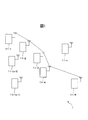
- FIG. 1 is a schematic configuration diagram of a radio communication system according to the first embodiment.
- FIG. 2 is a diagram illustrating an example of a relationship between a hop count and a selected resource pool.
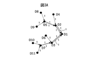
- FIG. 3A is a diagram illustrating an example of a resource pool selected by each mobile station according to a conventional method in a tree-like D2D link.
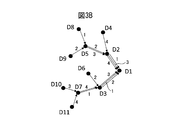
- FIG. 3B is a diagram showing an example of a resource pool selected by each mobile station according to the present embodiment in the same D2D link as the tree-like D2D link shown in FIG. 3A.
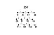
- FIG. 4A is a diagram illustrating an example of a resource pool selected by each mobile station according to a conventional method in a linear D2D link.
- FIG. 4B is a diagram illustrating an example of a resource pool selected by each mobile station according to the present embodiment in a linear D2D link.
- FIG. 5 is a sequence diagram of D2D communication in the wireless communication system 1 according to the present embodiment.
- FIG. 6 is a schematic configuration diagram of the mobile station apparatus.
- FIG. 7 is a functional block diagram of a control unit related to D2D communication.
- FIG. 8 is a schematic configuration diagram of a radio communication system according to the second embodiment.
- FIG. 9 is a schematic configuration diagram of a base station.
- a remote mobile station and a destination mobile station located outside a cell provided by a base station execute D2D communication via one or more relay mobile stations.
- a plurality of resource pools common to each mobile station are made available for both transmission and reception of data and call control.
- the remote mobile station performs carrier sensing, detects a resource pool in an idle state, and executes data and call control transmission using any resource in the resource pool.
- each relay mobile station determines whether its own device is based on a predetermined rule representing the relationship between the resource pool number used by the remote mobile station, the hop count in the relay mobile station, and the selected resource pool. Select the resource pool to be used. Thereby, the possibility that the same resource is selected in the remote mobile station and each relay mobile station is reduced, and as a result, the occurrence of collision and interference is reduced.
- the wireless communication system according to the present embodiment is, for example, a mobile communication system compliant with LTE-Advanced.
- the mobile stations located outside the cell provided by the base station can perform various other mobile units that can perform D2D communication via one or more relay mobile stations. It may be a communication system.
- FIG. 1 is a schematic configuration diagram of a radio communication system according to the first embodiment.
- the wireless communication system 1 includes a plurality of mobile stations 11-1 to 11-n (n is an integer of 3 or more). Each mobile station is an example of a communication device.
- the wireless communication system 1 may further include a base station (not shown) connected to the core network via an upper node (not shown).
- any of the plurality of mobile stations 11-1 to 11-n supports D2D communication and can operate as any of a remote mobile station, a destination mobile station, and a relay mobile station.
- Each mobile station is preinstalled with the same set of resource pools. Any resource pool included in the set of resource pools can be used for both transmission and reception of data or call control signals.
- the mobile station 11-1 is a remote mobile station
- the mobile station 11-5 is a destination mobile station
- the mobile stations 11-2 to 11-4 are relay mobile stations.
- any of the mobile stations 11-1 to 11-5 may be located outside the range of a cell provided by a base station (not shown), or may be a mobile station 11-1 that is a remote mobile station and Any one of the mobile stations 11-5 as the destination mobile station may be included in the cell range.
- the mobile station 11-1 which is a remote mobile station, finds another mobile station capable of D2D communication, for example, according to a predetermined Discovery procedure. Then, the mobile station 11-1 specifies a communication path by D2D communication to the mobile station 11-5 that is the destination mobile station, based on the other mobile stations that are found.
- the mobile station 11-1 selects a resource to be used for communication to the next relay mobile station on the communication path from a plurality of preinstalled resource pools.
- any of the plurality of preinstalled resource pools can be used for both transmission and reception of data or call control signals. Therefore, for each resource pool, the mobile station 11-1 performs carrier sensing for each resource included in the resource pool, and detects an unused resource pool, that is, an idle resource pool. For example, the mobile station 11-1 performs carrier sensing based on energy detection. That is, the mobile station 11-1 calculates the average value of the power detected in a predetermined period for each resource. Then, the mobile station 11-1 compares the detected average power value with a predetermined threshold value for each resource.
- the resource pool containing the resource is occupied by D2D communication by other mobile stations.
- the resource pool is assumed to be in an idle state, that is, usable. Therefore, the mobile station 11-1 selects a resource to be used from the resource pool in the idle state.
- the mobile station 11-1 performs carrier sensing only for some resources included in the resource pool for each resource pool, instead of performing carrier sensing for all resources. May be.
- the mobile station 11-1 performs carrier sensing for resources corresponding to the median, upper limit frequency, and lower limit frequency of the frequencies defined by each resource included in the resource pool. May be.
- the mobile station 11-1 can reduce the amount of computation required for carrier sensing.
- the mobile station 11-1 transmits data or a call control signal to the next relay mobile station 11-2 using the selected resource. At that time, the mobile station 11-1 transmits a synchronization signal such as PSSS / SSSS (Primary / Secandary Sidelink synchronization Signal) to synchronize the relay mobile station 11-2. The mobile station 11-1 then sends scheduling information such as resources used for data transmission to the next relay mobile station 11-2 via, for example, a Physical Sidelink Control Channel (PSCCH) defined based on a predetermined period. To notify. In addition, the mobile station 11-1 includes its own hop count (0 in the case of the mobile station 11-1) in predetermined control information and transmits the control information to the next relay mobile station 11-2. To do.
- PSSS / SSSS Primary / Secandary Sidelink synchronization Signal
- the predetermined control information may be, for example, information obtained by adding a hop count to SCI format0 defined in Release IV12. Then, the mobile station 11-1 uses the selected resource to transmit data to the relay mobile station 11-2 via Physical Sidelink Shared Channel (PSSCH).
- PSSCH Physical Sidelink Shared Channel
- Each of relay mobile stations 11-2 to 11-4 receives data from the previous relay mobile station or remote mobile station and transfers the data to the next relay mobile station or destination mobile station.
- Each of the relay mobile stations 11-2 to 11-4 receives data using the resource selected by the immediately preceding relay mobile station or remote mobile station. Then, each of the relay mobile stations 11-2 to 11-4 follows the predetermined rule based on the hop count of its own device and the resource pool number selected by the remote mobile station according to a predetermined rule. Select the resource pool to be used for data transfer to.
- FIG. 2 is a diagram showing an example of the relationship between the hop count and the selected resource pool.
- the arrows represent the order of mobile stations to which data is transferred. That is, in this example, data is transferred in the order of mobile station 11-1, mobile station 11-2, mobile station 11-3, mobile station 11-4, and mobile station 11-5. Therefore, the hop counts of the mobile stations 11-2 to 11-4 are 1, 2, and 3, respectively.
- the relay mobile station selects a resource pool having a number corresponding to a total value obtained by adding the hop count in the relay mobile station to the resource pool number selected by the remote mobile station 11-1. It is specified to be a resource pool. However, when the total value exceeds the maximum value of the resource pool number, the relay mobile station selects a resource pool having a number obtained by subtracting the maximum value of the resource pool number from the total value. In the example shown in FIG. 2, since the remote mobile station 11-1 has selected the nth resource pool, the mobile station 11-2 with a hop count of '1' has the (n + 1) th resource Select a pool.
- the mobile station 11-3 whose hop count is “2” selects the (n + 2) th resource pool
- the predetermined rule is not limited to the above example.
- a predetermined rule a resource pool whose relay mobile station selects a resource pool having a number corresponding to a value obtained by subtracting the hop count in the relay mobile station from the resource pool number selected by the remote mobile station 11-1. It may be prescribed to do.
- the resource pool numbers selected by the relay mobile stations 11-2 to 11-4 are (n ⁇ 1), (n-2), (n-3), respectively. ).
- the resource pool number calculated based on this rule is 0 or less, the number obtained by adding the maximum value of the resource pool number to the number becomes the number of the selected resource pool. Also good.
- a predetermined rule may be defined so that a resource pool having a different number is selected for each relay mobile station having at least a continuous hop count.
- Each relay mobile station transfers data received from the previous relay mobile station or remote mobile station to the next relay mobile station or destination mobile station using any of the resources belonging to the resource pool selected by the own device. To do. At that time, each relay mobile station may transfer data by the same procedure as that of the remote mobile station 11-1. Each relay mobile station may transfer data in accordance with any of the layer 1 to layer 3 relay methods. Also, each relay mobile station includes its own hop count in predetermined control information and transmits the control information to the next relay mobile station, as with mobile station 11-1.
- remote mobile station and each relay mobile station may select the resource pool to be used in accordance with the same procedure as described above for the D2D communication call control signal communicated via the PSCCH.
- the probability that collision or interference occurs when a resource pool is selected according to the conventional method and the collision or interference when resource pool is selected according to this embodiment are as follows. The probability of occurrence will be described.
- FIG. 3A is a diagram showing an example of a resource pool selected by each mobile station according to a conventional method in a tree-like D2D link.
- FIG. 3B is a diagram showing an example of a resource pool selected by each mobile station according to the present embodiment in the same D2D link as the tree-like D2D link shown in FIG. 3A.
- D1 to D11 each represent a mobile station.
- Each arrow represents a link between mobile stations.
- a mobile station on the base side of the arrow transmits data, and a mobile station on the tip side of the arrow receives data.
- a numerical value attached in the vicinity of each arrow represents a resource pool number used in the D2D communication indicated by the corresponding arrow.
- each mobile station has four resource pools.
- the first resource pool is used in each D2D communication.
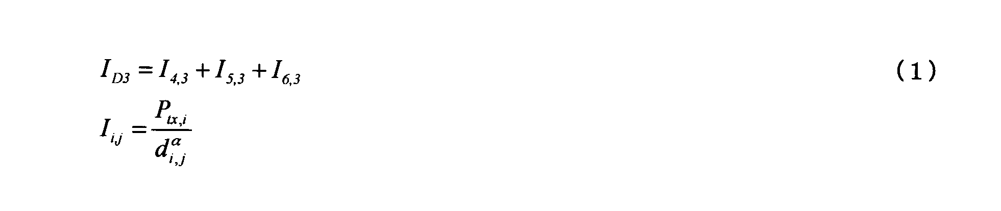
- interference that may occur with a radio wave used for data communication from the mobile station D7 is expressed by the following equation.
- ⁇ is a propagation loss index.
- each relay mobile station uses a resource different from the resource used for data reception from the previous mobile station.
- interference that may occur with radio waves used for data communication from mobile station D3 is expressed by the following equation.
- the remote mobile station selects a resource pool determined to be in an idle state from among a plurality of resource pools as a result of carrier sensing, and enters the resource pool.
- Each relay mobile station selects a resource pool according to the resource pool number selected by the remote mobile station and the hop count of the own device. Therefore, as shown in FIG. 3B, the resource pools used are different between adjacent links.
- attention is paid to data communication received from the mobile station D11 via the mobile station D7 in the mobile station D3, as described above.
- the resource pool '1' used for this data communication is different from any of the resource pools used by the mobile stations D4, D5, and D6 that have transmitted radio waves that may cause interference in the prior art. . Therefore, no interference occurs in this data communication.
- FIG. 4A is a diagram illustrating an example of a resource pool selected by each mobile station according to a conventional method in a linear D2D link.
- FIG. 4B is a diagram illustrating an example of a resource pool selected by each mobile station according to the present embodiment in a linear D2D link.
- D1 to D12 each represent a mobile station.
- Each arrow represents a link between mobile stations.
- a mobile station on the base side of the arrow transmits data, and a mobile station on the tip side of the arrow receives data.
- a numerical value attached in the vicinity of each arrow represents a resource pool number used in the D2D communication indicated by the corresponding arrow.
- each mobile station has four resource pools.
- the only resource pool that can be used for both data transmission and reception is the first resource pool. Therefore, as shown in FIG. 4A, the first resource pool is used in each D2D communication. Therefore, for example, in the mobile station D9, interference that may occur for radio waves used for data communication from the mobile station D10 is expressed by the following equation. However, it is assumed that the mobile stations D3, D7, and D11 are only receiving data while the mobile stations D4, D8, and D9 are transmitting data.
- the remote mobile station selects a resource pool determined to be in an idle state from among a plurality of resource pools as a result of carrier sensing, and enters the resource pool.
- Each relay mobile station selects a resource pool according to the resource pool number selected by the remote mobile station and the hop count of the own device. Therefore, as shown in FIG. 4B, the resource pools used are different between adjacent links. Therefore, for example, as in the above, attention is paid to data communication from the mobile station D10 in the mobile station D9.
- the mobile station D4 among the mobile stations D4, D8, D8, D12, D2, and D6 that transmitted radio waves that may cause interference in the prior art is a resource pool used for this data communication.
- N rp is the number of resources included in one resource pool.
- no collision occurs.
- FIG. 5 is a sequence diagram of D2D communication in the wireless communication system 1 according to the present embodiment.
- the remote mobile station 11-1 performs carrier sensing on each resource pool to detect an idle resource pool, and selects a resource pool to be used from the detected idle resource pool (step S1). S101). Then, the remote mobile station 11-1 transmits the resource allocation information and the hop count “0” of the remote mobile station 11-1 to the first relay mobile station 11-2. Thereafter, the remote mobile station 11-1 transmits data using the resource indicated by the resource allocation information.
- the relay mobile station 11-2 refers to the resource allocation information and receives data transmitted using the designated resource. Further, the relay mobile station 11-2 calculates the hop count “1” of the own device from the notified hop count. Then, the relay mobile station 11-2 selects a resource pool to be used for data transfer according to a predetermined rule based on the resource pool number selected by the remote mobile station 11-1 and the hop count “1” of its own device ( Step S102). Then, the relay mobile station 11-2 transmits the resource allocation information and the hop count “1” of the relay mobile station 11-2 to the next relay mobile station 11-3. Thereafter, the relay mobile station 11-2 transmits data using the resource indicated by the resource allocation information.
- the relay mobile station 11-3 refers to the resource allocation information and receives the data transferred using the designated resource. Also, the relay mobile station 11-3 calculates its own hop count “2” from the notified hop count. Then, the relay mobile station 11-3 selects a resource pool to be used for data transfer according to a predetermined rule based on the resource pool number selected by the remote mobile station 11-1 and the hop count “2” of its own device ( Step S103). Then, the relay mobile station 11-3 transmits the resource allocation information and the hop count “2” of the relay mobile station 11-3 to the next relay mobile station 11-4. Thereafter, the relay mobile station 11-3 transfers data using the resource indicated by the resource allocation information.
- the relay mobile station 11-4 refers to the resource allocation information and receives data transferred using the specified resource. Further, the relay mobile station 11-4 calculates its own hop count “3” from the notified hop count. Then, the relay mobile station 11-4 selects a resource pool to be used for data transfer according to a predetermined rule based on the resource pool number selected by the remote mobile station 11-1 and the hop count '3' of its own device ( Step S104). The relay mobile station 11-4 transmits the resource allocation information to the destination mobile station 11-5. Thereafter, the relay mobile station 11-4 transfers the data using the resource indicated by the resource allocation information. As described above, data is transmitted from the remote mobile station 11-1 to the destination mobile station 11-5.
- each mobile station included in the wireless communication system 1 may have the same configuration. Therefore, the mobile station 11-1 will be described below.
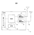
- FIG. 6 is a schematic configuration diagram of the mobile station 11-1.
- the mobile station 11-1 includes a transmission antenna 21, a reception antenna 22, a transmission wireless processing unit 23, a reception wireless processing unit 24, a storage unit 25, and a control unit 26.
- the transmission wireless processing unit 23, the reception wireless processing unit 24, the storage unit 25, and the control unit 26 are formed as separate circuits. Alternatively, each of these units may be mounted on the mobile station 11-1 as one or a plurality of integrated circuits in which circuits corresponding to the respective units are integrated.
- the transmission antenna 21 transmits an uplink signal transmitted via the transmission radio processing unit 23 or various transmission signals in D2D communication as a radio signal.
- the receiving antenna 22 receives a downlink signal, which is a radio signal from the base station, converts it into an electric signal, and transmits the downlink signal converted into the electric signal to the receiving radio processing unit 24.
- the reception antenna 22 receives various radio signals in D2D communication from other mobile stations, converts them into electrical signals, and transmits the converted signals to the reception radio processing unit 24.
- the transmission radio processing unit 23 converts the multiplexed transmission signal (for example, uplink signal or various signals in D2D communication) received from the control unit 26 into an analog signal, and then is designated by the control unit 26. Superimposed on a carrier wave with a different radio frequency. Then, the transmission radio processing unit 23 amplifies the uplink signal superimposed on the carrier wave to a desired level by a high power amplifier (not shown), and transmits the signal to the transmission antenna 21.
- a high power amplifier not shown
- the reception wireless processing unit 24 amplifies a signal (for example, a downlink signal or various signals in D2D communication) received from the reception antenna 22 by a low noise amplifier (not shown).
- the reception radio processing unit 24 multiplies the amplified signal by a periodic signal having an intermediate frequency to convert the frequency of the signal from a radio frequency to a baseband frequency.
- the reception radio processing unit 24 performs analog / digital conversion on the signal having the baseband frequency, and then passes the signal to the control unit 26.
- the storage unit 25 includes, for example, a rewritable nonvolatile semiconductor memory or volatile semiconductor memory.
- the storage unit 25 stores various types of information for communicating with the base station, various types of information transmitted or received by the mobile station 11-1, and various programs that operate on the mobile station 11-1. Furthermore, the storage unit 25 stores various information used in D2D communication, such as a resource pool set.
- the control unit 26 includes, for example, one or a plurality of processors and their peripheral circuits. Then, the control unit 26 performs processing such as error correction coding on the uplink signal. Further, the control unit 26 modulates and multiplexes the uplink signal according to a predetermined modulation scheme.
- the multiplexing scheme may be, for example, a single carrier frequency division multiplexing scheme (Single-Carrier-Frequency-Division-Multiplexing, SC-FDMA). Then, the control unit 26 passes the modulated and multiplexed downlink signal to the transmission radio processing unit 23.
- control unit 26 separates the downlink signal received from the reception radio processing unit 24 according to a predetermined multiplexing method, demodulates the separated downlink signal, and performs error correction decoding.
- the multiplexing method for the downlink signal can be, for example, an orthogonal frequency division multiplexing (OFDM).
- OFDM orthogonal frequency division multiplexing
- the control part 26 takes out an audio
- the control unit 26 reproduces the extracted audio signal through a speaker (not shown) or displays a moving image signal and data on a display (not shown).
- control unit 26 executes various processes for executing wireless communication such as transmission power control and call control.
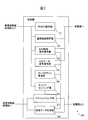
- FIG. 7 is a functional block diagram of the control unit 26 related to D2D communication.
- the control unit 26 includes a PDSCH decoding unit 31, a communication path setting unit 32, a D2D control signal decoding unit 33, a D2D data signal decoding unit 34, a carrier sensing unit 35, a hop count calculation unit 36, and a scheduling unit 37. And a transmission data generation unit 38.
- Each of these units included in the control unit 26 is realized by a computer program that operates on a processor included in the control unit 26.
- each of these units included in the control unit 26 may be implemented in the mobile station 11-1 as one or a plurality of integrated circuits in which circuits for realizing the functions of the respective units are integrated.
- the PDSCH decoding unit 31 When the mobile station 11-1 is located in a cell provided by the base station, the PDSCH decoding unit 31 includes a downlink shared channel (Physical Downlink Shared Channe, PDSCH) included in the downlink signal from the base station. Decode the signal. The PDSCH decoding unit 31 extracts a set of resource pools used when the mobile station 11-1 is located in a cell provided by the base station from the decoded signal, and stores it in the storage unit 25.
- PDSCH Physical Downlink Shared Channe
- the communication path setting unit 32 specifies, for example, a communication path to the destination mobile station and a relay mobile station existing on the communication path.
- the communication path setting unit 32 performs a Discovery process to detect other mobile stations around the mobile station 11-1.
- the Discover process itself may be compliant with LTE Release 12.
- the communication path setting unit 32 generates various transmission signals used in the discovery process, for example, a discovery message such as a discovery request message or a discovery response message. Then, the communication path setting unit 32 outputs the transmission signal to the transmission wireless processing unit 23. Further, the communication path setting unit 32 decodes a signal related to the discovery process from another mobile station, which is included in the signal received from the reception wireless processing unit 24.
- the communication path setting unit 32 When the mobile station 11-1 is a remote mobile station, the communication path setting unit 32 generates a Discovery message including the identification information of the destination mobile station, and transmits the Discovery message to the transmission radio processing unit 23 and the transmission antenna 21. Send through. Then, the communication path setting unit 32 refers to the information regarding the measurement value of the received power included in the Discovery Response message from one or more mobile stations responding to the Discovery message, and selects the mobile station with the highest received power as the first. Relay mobile station. Then, the communication path setting unit 32 generates a control signal including information indicating that the first relay mobile station is designated as the relay mobile station, and transmits the control signal to the transmission wireless processing unit 23 and the transmission mobile station. Transmit via antenna 21.
- the communication path setting unit 32 identifies them. A communication path to the destination mobile station is specified based on the information. Then, the communication path setting unit 32 stores the identification information of each mobile station on the communication path and the order of passing through in the storage unit 25.
- the communication path setting unit 32 measures the received power of the radio wave from the mobile station. Then, the communication path setting unit 32 generates a Discovery Response message including information related to the measured value of the received power and the identification information of the mobile station 11-1, and sends the Discovery Response message to the transmission radio processing unit 23 and the transmission antenna 21. Reply via
- the communication path setting unit 32 When the communication path setting unit 32 receives control information indicating that it has been designated as a relay mobile station, the communication path setting unit 32 includes Discover information including remote mobile station identification information, own apparatus identification information, and destination mobile station identification information. Generate a message. Then, the communication path setting unit 32 transmits the message to the neighboring mobile station via the transmission radio processing unit 23 and the transmission antenna 21.
- the communication path setting unit 32 refers to the information related to the measurement value of the received power included in the Discovery ⁇ ⁇ ⁇ ⁇ ⁇ Response message from one or more mobile stations responding to the Discovery message, and the mobile station with the highest received power is relayed to the next relay station. A mobile station. Then, the communication path setting unit 32 generates a control signal including information indicating that the next relay mobile station is designated as the relay mobile station, and transmits the control signal to the transmission radio processing unit 23 and the transmission antenna. 21 to transmit. In addition, the communication path setting unit 32 sends a control signal including identification information of the own device and the relay mobile stations subsequent to the own device via the transmission wireless processing unit 23 and the transmission antenna 21 to the previous relay mobile station or remote Send to the mobile station.
- the D2D control signal decoding unit 33 is received from another mobile station (for example, a remote mobile station or the previous relay mobile station) by D2D communication, and is included in the signal received via the reception radio processing unit 24.
- a control signal transmitted via PSCCH or the like is decoded.
- This control signal also includes, for example, a signal conforming to SCI Format 0 that has been modified to include a hop count, and schedule allocation information.
- the D2D control signal decoding unit 33 extracts the hop count from the SCI Format0 and notifies the hop count calculation unit 36 of it. Further, the D2D control signal decoding unit 33 extracts schedule allocation information from the control signal and passes the information to the D2D data signal decoding unit 34.
- the D2D data signal decoding unit 34 decodes the D2D communication signal received via the reception wireless processing unit 24. At that time, the D2D data signal decoding unit 34 uses a signal corresponding to the resource specified by the schedule assignment information as a signal to the own device or a signal to be relayed by the own device.
- the carrier sensing unit 35 When the mobile station 11-1 is a remote mobile station, the carrier sensing unit 35 performs carrier sensing for each resource included in a pre-configured resource pool set in order to determine a resource to be used. To do. As described above, the carrier sensing unit 35 calculates an average value of power detected in a predetermined period for each resource. And the carrier sensing part 35 compares the average value of the detected electric power with a predetermined threshold value for every resource.
- the carrier sensing unit 35 detects a resource pool in which the average value of detected power for all the included resources is equal to or less than a predetermined threshold, that is, an idle resource pool, and sets the number of the detected resource pool to the scheduling unit 37. To notify.
- the hop count calculation unit 36 increments the hop count of the previous relay mobile station or remote mobile station received from the D2D control signal decoding unit 33 by one. Then, the hop count calculation unit 36 sets the incremented hop count as the hop count of the own device. Then, the hop count calculation unit 36 notifies the scheduling unit 37 of the hop count of the own device.
- the scheduling unit 37 uses any of the resources included in the resource pool identified by the resource pool number notified from the carrier sensing unit 35 for D2D communication. Select as a resource. Note that the resource selected in the identified resource pool is arbitrary.
- the scheduling unit 37 uses the own device according to a predetermined rule based on the hop count of the own device and the resource pool number selected by the remote mobile station. Select the resource pool to be used. Then, the scheduling unit 37 selects any of the resources included in the selected resource pool as a resource used for D2D communication. Also in this case, the resource selected in the specified resource pool is arbitrary.
- the scheduling unit 37 generates a control signal for D2D communication including the hop count of the own device and scheduling allocation information indicating the selected resource. Then, the scheduling unit 37 transmits the control signal to the next relay mobile station or destination mobile station via the transmission radio processing unit 23 and the transmission antenna 21.
- the transmission data generation unit 38 generates a transmission signal including data for transmission so that the selected resource is used. Then, the transmission data generation unit 38 transmits the transmission signal to the next relay mobile station or destination mobile station via the transmission radio processing unit 23 and the transmission antenna 21. When the mobile station 11-1 is a relay mobile station, the transmission data generation unit 38 transmits data received from the remote mobile station or the previous relay mobile station from the D2D data signal decoding unit 34 as a transmission signal. The data to be included in the transmission.
- each of a plurality of pre-built resource pools can be used for data transmission / reception. And Then, the remote mobile station performs carrier sensing to detect an idle resource pool, and uses any resource included in the detected resource pool for data transmission.
- the relay mobile station that relays D2D communication selects a resource pool according to a predetermined rule based on the resource pool number selected by the remote mobile station and the hop count of the own device.
- the hop count of each relay mobile station may be included in the control signal of the discovery process that is notified from the remote mobile station during the discovery process. Then, the hop count may be notified to each relay mobile station by transferring the control signal via each relay mobile station.
- one relay mobile station relays communication between a plurality of remote mobile stations and a base station.
- FIG. 8 is a schematic configuration diagram of a wireless communication system according to the second embodiment.
- the wireless communication system 2 according to the second embodiment includes a plurality of mobile stations 11-1 to 11-4 and a base station 12.
- the base station 12 is another example of a communication device.
- any of the plurality of mobile stations 11-1 to 11-4 supports D2D communication, and can operate as any of a remote mobile station, a destination mobile station, and a relay mobile station.
- Each mobile station is preinstalled with the same set of resource pools. Any resource pool included in the set of resource pools can be used for both transmission and reception of data or call control signals.
- the mobile station 11-1 is a relay mobile station and the mobile stations 11-2 to 11-4 are remote mobile stations.
- the mobile station 11-1 is located within the range of the cell 12a provided by the base station 12, while any of the mobile stations 11-2 to 11-4 is located outside the range of the cell 12a. Assume that
- the hop count of the mobile station 11-1 is “1”. Therefore, if the resource pools selected by the mobile stations 11-2 to 11-4 are the same, when the resource pool is selected as in the above embodiment, each relay mobile station 11-1 also performs each D2D communication.
- the resource pool selected for is the same.
- the base station 12 selects a resource pool to be used in each remote mobile station so that the resource pools assigned to the remote mobile stations 11-2 to 11-4 are different from each other.
- each of the remote mobile stations 11-2 to 11-4 sets the status of the mobile station used for selection of the resource pool in one of the control signals in the discovery process transmitted to the relay mobile station 11-1.
- the parameter includes, for example, at least one of a parameter representing the environment of the own device, a parameter representing the communication state, and a parameter representing the urgency of communication.
- the parameter representing the environment of the own device is, for example, a parameter representing the position of the own device and the speed of the own device.
- the parameter representing the communication state is a parameter representing the wireless measurement result, for example.
- Relay mobile station 11-1 then transfers the parameters received from each of remote mobile stations 11-2 to 11-4 to base station 12.
- the base station 12 sets a resource pool to be assigned to each of the remote mobile stations 11-2 to 11-4 based on parameters representing the states of the remote mobile stations 11-2 to 11-4. For example, the base station 12 sets different resource pools for a plurality of remote mobile stations within a predetermined distance. Further, a plurality of remote mobile stations that are located within a predetermined distance and have the same speed may belong to the same group. Therefore, the base station 12 allocates the same resource pool to a plurality of remote mobile stations that are located within a predetermined distance and have the same speed. Different resource pools may be set for a plurality of remote mobile stations. Further, the base station 12 may assign different resource pools in order from the remote mobile station having the larger received power or the smaller received power indicated by the wireless measurement result. Furthermore, the base station 12 may assign the resource pool in order from the remote mobile station with the highest urgency when the parameter representing the state of the mobile station includes a parameter representing the urgency of communication.
- the base station 12 can assign resource pools that are orthogonal to each other to different remote mobile stations.
- the resource pools that are orthogonal to each other include, for example, resources that are orthogonal to the resources included in the other resource pool with respect to the frequency.
- One schedule allocation information can indicate a plurality of resource pools that are orthogonal together with resources at the same position in each resource pool. Therefore, the base station 12 can notify the resource pool used in each remote mobile station only by transmitting a single schedule allocation information. Therefore, the overhead of call control from the relay mobile station 11-1 to each of the remote mobile stations 11-2 to 11-4 is reduced.
- the relay mobile station 11-1 can transfer data from the base station 12 to each of the remote mobile stations within one schedule allocation period. At that time, during the connection establishment period, the relay mobile station 11-1 may assign destination identification information in the data link layer (layer 2) to each of the remote mobile stations. In addition, each of the remote mobile stations can identify the reception data in the data link layer and the reception data in the network layer (layer 3). Therefore, when each remote mobile station has common data link layer destination identification information, each remote mobile station uses an address in the network layer, for example, an IP address to receive data. It may be determined which remote mobile station is addressed.
- each of the remote mobile stations and the base station may be relayed by a plurality of relay mobile stations arranged in series in the same manner as each relay mobile station in FIG. And each relay mobile station should just select the resource pool which an own apparatus uses based on the hop count of an own apparatus, and the number of the resource pool which the remote mobile station selected similarly to 1st Embodiment.
- FIG. 9 is a schematic configuration diagram of the base station 12.
- the base station 12 includes a transmission antenna 41, a reception antenna 42, a transmission radio processing unit 43, a reception radio processing unit 44, a wired interface unit 45, a storage unit 46, and a control unit 47.
- the transmission wireless processing unit 43, the reception wireless processing unit 44, the wired interface unit 45, the storage unit 46, and the control unit 47 are formed as separate circuits. Alternatively, each of these units may be mounted on the base station 12 as one or a plurality of integrated circuits in which circuits corresponding to the respective units are integrated.
- the transmission antenna 41 transmits the downlink signal transmitted via the transmission radio processing unit 43 as a radio signal.
- the reception antenna 42 receives an uplink signal, which is a radio signal from the mobile station, converts it into an electrical signal, and transmits the uplink signal converted into the electrical signal to the reception radio processing unit 44.
- the reception antenna 22 receives various radio signals in D2D communication from other mobile stations, converts them into electrical signals, and transmits the converted signals to the reception radio processing unit 44.
- the transmission radio processing unit 43 analogizes the multiplexed downlink signal received from the control unit 47 and then superimposes it on a carrier wave having a radio frequency designated by the control unit 47.
- the transmission radio processing unit 43 amplifies the downlink signal superimposed on the carrier wave to a desired level by a high power amplifier (not shown), and transmits the signal to the transmission antenna 41.
- the reception radio processing unit 44 amplifies the uplink signal received from the reception antenna 42 by a low noise amplifier (not shown).
- the reception radio processing unit 44 converts the frequency of the uplink signal from a radio frequency to a baseband frequency by multiplying the amplified uplink signal by a periodic signal having an intermediate frequency. Then, the reception radio processing unit 44 performs analog / digital conversion on the uplink signal having the baseband frequency, and then passes the uplink signal to the control unit 47.
- This uplink signal includes a signal from any of the remote mobile stations 11-2 to 11-4 relayed by the relay mobile station 11-1.
- the wired interface unit 45 has a communication interface circuit for connecting the base station 12 to an upper node device (not shown) and other base stations. Then, the wired interface unit 45 analyzes the signal received from the higher order node device according to the S1 interface, and extracts the downlink signal and the control signal included in the signal. Further, the wired interface unit 45 analyzes a signal received from another base station according to the X2 interface, and extracts a control signal included in the signal. Then, the wired interface unit 45 passes the extracted downlink signal and control signal to the control unit 47.
- the wired interface unit 45 converts the uplink signal received from the control unit 47 into a signal in a format according to the S1 interface and then outputs the signal to the upper node device.
- the wired interface unit 45 converts a control signal to be transmitted to another base station into a format according to the X2 interface. Then, the wired interface unit 45 outputs the control signal to another base station.
- the storage unit 46 includes, for example, a rewritable nonvolatile semiconductor memory or volatile semiconductor memory. And the memory
- the control unit 47 includes, for example, one or a plurality of processors and their peripheral circuits. Then, the control unit 47 performs processing such as error correction coding on the downlink signal. Furthermore, the control unit 47 modulates and multiplexes the downlink signal according to a predetermined modulation scheme. Note that the multiplexing method can be, for example, OFDM. Then, the control unit 47 passes the modulated and multiplexed downlink signal to the transmission radio processing unit 43.
- control unit 47 separates the uplink signal received from the reception radio processing unit 44 according to a predetermined multiplexing method, demodulates the separated uplink signal, and performs error correction decoding.
- the multiplexing scheme for uplink signals can be, for example, SC-FDMA.
- the control unit 47 outputs the decoded uplink signal to the wired interface unit 45.
- the control unit 47 extracts various signals referred to by the base station 12 from the decoded uplink signal, for example, control information related to call control or parameters representing a state from a remote mobile station.
- control unit 47 executes various processes for executing wireless communication with the mobile station such as transmission power control and call control. Further, the control unit 47 selects a resource pool to be used by each remote mobile station based on the parameter representing the state of the mobile station received from each remote mobile station via the relay mobile station. At that time, as described above, the control unit 47 selects resource pools so that the allocated resource pools are different from each other for a plurality of remote mobile stations that use the same relay mobile station.
Landscapes
- Engineering & Computer Science (AREA)
- Computer Networks & Wireless Communication (AREA)
- Signal Processing (AREA)
- Mobile Radio Communication Systems (AREA)
Abstract
Description
複数の通信装置のうち、第1の通信装置と第2の通信装置間の無線通信を中継する少なくとも一つの第3の通信装置のそれぞれは、その無線通信における第3の通信装置でのホップカウントと、第1の通信装置が選択したリソースプールとに基づいて規定される所定の規則に従ってリソースプールのセットの中から何れかのリソースプールを選択し、選択したリソースプールに含まれる何れかのリソースを利用して、第2の通信装置宛ての信号を少なくとも一つの第3の通信装置のうちの中継順序が次の通信装置または第2の通信装置へ転送することを含む。
この無線通信システムでは、基地局が提供するセルの外に位置するリモート移動局と宛先移動局とが1以上の中継移動局を介してD2D通信を実行する。その際、各移動局について共通する複数のリソースプールがデータ及び呼制御の送信と受信の両方について使用可能とされる。そしてリモート移動局は、キャリアセンシングを行って、アイドル状態にあるリソースプールを検出し、そのリソースプール内の何れかのリソースを使用して、データ及び呼制御の送信を実行する。一方、各中継移動局は、リモート移動局が使用したリソースプールの番号、及び、その中継移動局におけるホップカウントと、選択されるリソースプールとの関係を表す所定の規則に基づいて、自装置が使用するリソースプールを選択する。これにより、リモート移動局及び各中継移動局にて同じリソースが選択される可能性が低減し、その結果として、コリジョン及び干渉の発生が低減される。

先ず、リモート移動局11-1は、各リソースプールに対してキャリアセンシングを実行してアイドル状態のリソースプールを検出し、検出したアイドル状態のリソースプールの中から使用するリソースプールを選択する(ステップS101)。そしてリモート移動局11-1は、最初の中継移動局11-2へ、リソース割り当て情報及びリモート移動局11-1のホップカウント'0'を送信する。その後、リモート移動局11-1は、リソース割り当て情報で示されるリソースを用いて、データを送信する。
以上により、リモート移動局11-1から宛先移動局11-5へデータが送信される。
図7は、D2D通信に関連する、制御部26の機能ブロック図である。制御部26は、PDSCH復号部31と、通信経路設定部32と、D2D制御信号復号部33と、D2Dデータ信号復号部34と、キャリアセンシング部35と、ホップカウント算出部36と、スケジューリング部37と、送信データ生成部38とを有する。制御部26が有するこれらの各部は、制御部26が有するプロセッサ上で動作するコンピュータプログラムにより実現される。あるいは、制御部26が有するこれらの各部は、その各部の機能を実現する回路が集積された一つまたは複数の集積回路として移動局11-1に実装されてもよい。
さらに、制御部47は、各リモート移動局から中継移動局を介して受信した、移動局の状態を表すパラメータに基づいて、各リモート移動局が利用するリソースプールを選択する。その際、制御部47は、上記のように、同一の中継移動局を利用する、複数のリモート移動局について、割り当てられるリソースプールが互いに異なるようにリソースプールを選択する。
11-1~11-n 移動局
12 基地局
21、41 送信用アンテナ
22、42 受信用アンテナ
23、43 送信用無線処理部
24、44 受信用無線処理部
45 有線インターフェース部
25、46 記憶部
26、47 制御部
31 PDSCH復号部
32 通信経路設定部
33 D2D制御信号復号部
34 D2Dデータ信号復号部
35 キャリアセンシング部
36 ホップカウント算出部
37 スケジューリング部
38 送信データ生成部
Claims (14)
- 複数の通信装置を有する無線通信システムであって、
前記複数の通信装置のそれぞれは、前記複数の通信装置のうちの他の通信装置との無線通信に利用可能な周波数及び時間を規定するリソースを複数含むリソースプールの共通するセットを記憶し、
前記複数の通信装置のうちの第1の通信装置は、前記リソースプールのセットの中から何れかのリソースプールを選択し、選択したリソースプールに含まれる何れかのリソースを利用して、前記複数の通信装置のうちの第2の通信装置宛ての信号を送信し、
前記複数の通信装置のうち、前記第1の通信装置と前記第2の通信装置間の無線通信を中継する少なくとも一つの第3の通信装置のそれぞれは、前記無線通信における当該第3の通信装置でのホップカウントと、前記第1の通信装置が選択したリソースプールとに基づいて規定される所定の規則に従って前記リソースプールのセットの中から何れかのリソースプールを選択し、選択したリソースプールに含まれる何れかのリソースを利用して、前記第2の通信装置宛ての信号を前記少なくとも一つの第3の通信装置のうちの中継順序が次の通信装置または前記第2の通信装置へ転送する、
無線通信システム。 - 前記所定の規則は、前記少なくとも一つの第3の通信装置のうち、連続する前記ホップカウントを有する第3の通信装置のそれぞれに対して、前記リソースプールのセットの中から互いに異なるリソースプールが選択されるように規定される、請求項1に記載の無線通信システム。
- 前記複数のリソースプールのそれぞれは互いに異なる番号を有し、
前記所定の規則は、前記第1の通信装置が選択したリソースプールの番号に前記ホップカウントが加算された番号を有するリソースプールが選択されるように規定される、請求項2に記載の無線通信システム。 - 前記第1の通信装置は、前記リソースプールのセットに含まれるリソースプールのそれぞれについてキャリアセンシングを実行して1以上のアイドル状態のリソースプールを検出し、前記検出した1以上のアイドル状態のリソースプールの中から何れかのリソースプールを選択する、請求項1~3の何れか一項に記載の無線通信システム。
- 前記第1の通信装置、前記第2の通信装置及び前記少なくとも一つの第3の通信装置のそれぞれは移動局である、請求項1~4の何れか一項に記載の無線通信システム。
- 前記複数の通信装置のうちの第4の通信装置は、前記少なくとも一つの第3の通信装置を中継して前記第2の通信装置と無線通信し、かつ、前記少なくとも一つの第3の通信装置のそれぞれについて、前記第1の通信装置と前記第2の通信装置間の無線通信におけるホップカウントと、前記第4の通信装置と前記第2の通信装置間の無線通信におけるホップカウントは同一であり、
前記第1の通信装置は、前記少なくとも一つの第3の通信装置を介して前記第2の通信装置へ前記第1の通信装置の状態を表すパラメータを通知し、かつ、前記第4の通信装置は、前記少なくとも一つの第3の通信装置を介して前記第2の通信装置へ前記第4の通信装置の状態を表すパラメータを通知し、
前記第2の通信装置は、前記第1の通信装置から通知された前記パラメータ及び前記第4の通信装置から通知された前記パラメータに基づいて、前記第1の通信装置が使用するリソースプールと前記第4の通信装置が使用するリソースプールとを設定し、前記少なくとも一つの第3の通信装置を中継して、設定したリソースプールを前記第1の通信装置及び前記第4の通信装置へ通知する、請求項1~3の何れか一項に記載の無線通信システム。 - 前記第1の通信装置の状態を表すパラメータは、前記第1の通信装置の環境を表すパラメータ、前記第1の通信装置の通信状態を表すパラメータ、及び、通信の緊急度を表すパラメータのうちの少なくとも一つを含む、請求項6に記載の無線通信システム。
- 前記第2の通信装置は、前記第1の通信装置が使用するリソースプールと前記第4の通信装置が使用するリソースプールとが互いに異なるように、前記リソースプールのセットの中から前記第1の通信装置が使用するリソースプールと前記第4の通信装置が使用するリソースプールとを設定する、請求項6に記載の無線通信システム。
- 前記第2の通信装置は、前記第1の通信装置が使用するリソースプールと前記第4の通信装置が使用するリソースプールとが互いに直交関係となるように、前記第1の通信装置が使用するリソースプールと前記第4の通信装置が使用するリソースプールとを設定する、請求項6に記載の無線通信システム。
- 前記第2の通信装置は、前記第1の通信装置が使用するリソースプールを表す情報と前記第4の通信装置が使用するリソースプールを表す情報とを含む一つのスケジュール割り当て情報を生成し、当該一つのスケジュール割り当て情報を前記少なくとも一つの第3の通信装置を介して前記第1の通信装置及び前記第4の通信装置へ送信する、請求項9に記載の無線通信システム。
- 前記第2の通信装置は基地局であり、前記第1の通信装置、前記第4の通信装置及び前記少なくとも一つの第3の通信装置のそれぞれは移動局である、請求項6~10の何れか一項に記載の無線通信システム。
- 第1の他の移動局と第2の他の移動局との無線通信を中継する移動局であって、
前記移動局が前記第2の他の移動局との無線通信に利用可能な周波数及び時間を規定するリソースを複数含むリソースプールのセットを記憶する記憶部と、
前記無線通信における前記移動局でのホップカウントと、前記第1の他の移動局が前記リソースプールのセットの中から選択したリソースプールとに基づいて規定される所定の規則に従って前記リソースプールのセットの中から何れかのリソースプールを選択し、前記選択したリソースプールに含まれる何れかのリソースを利用して、前記無線通信を中継する制御部と、
を有する移動局。 - 複数の移動局のそれぞれと、少なくとも一つの他の移動局の中継により無線通信する基地局であって、
前記複数の移動局のそれぞれが前記少なくとも一つの他の移動局との無線通信に利用可能な周波数及び時間を規定するリソースを複数含むリソースプールのセットを記憶する記憶部と、
前記複数の移動局のそれぞれから通知された、当該移動局の状態を表すパラメータに基づいて、前記リソースプールのセットの中から前記複数の移動局のそれぞれごとに、当該移動局が使用するリソースプールを設定し、前記少なくとも一つの他の移動局を介して、前記複数の移動局のそれぞれに対して設定したリソースプールを通知する制御部と、
を有する基地局。 - 複数の通信装置を有する無線通信システムにおける無線通信方法であって、
前記複数の通信装置のうちの第1の通信装置は、前記複数の通信装置のそれぞれが記憶する、前記複数の通信装置のうちの他の通信装置との無線通信に利用可能な周波数及び時間を規定するリソースを複数含むリソースプールのセットの中から何れかのリソースプールを選択し、選択したリソースプールに含まれる何れかのリソースを利用して、前記複数の通信装置のうちの第2の通信装置宛ての信号を送信し、
前記複数の通信装置のうち、前記第1の通信装置と前記第2の通信装置間の無線通信を中継する少なくとも一つの第3の通信装置のそれぞれは、前記無線通信における当該第3の通信装置でのホップカウントと、前記第1の通信装置が選択したリソースプールとに基づいて規定される所定の規則に従って前記リソースプールのセットの中から何れかのリソースプールを選択し、選択したリソースプールに含まれる何れかのリソースを利用して、前記第2の通信装置宛ての信号を前記少なくとも一つの第3の通信装置のうちの中継順序が次の通信装置または前記第2の通信装置へ転送する、
ことを含む無線通信方法。
Priority Applications (5)
| Application Number | Priority Date | Filing Date | Title |
|---|---|---|---|
| CN201680084470.8A CN108886764B (zh) | 2016-04-12 | 2016-04-12 | 移动站、基站、无线通信系统及无线通信方法 |
| JP2018511804A JP6801709B2 (ja) | 2016-04-12 | 2016-04-12 | 無線通信システム、移動局及び無線通信方法 |
| EP16898593.5A EP3445105B1 (en) | 2016-04-12 | 2016-04-12 | Mobile station, base station, wireless communication system, and wireless communication method |
| PCT/JP2016/061845 WO2017179133A1 (ja) | 2016-04-12 | 2016-04-12 | 移動局、基地局、無線通信システム及び無線通信方法 |
| US16/137,764 US10735977B2 (en) | 2016-04-12 | 2018-09-21 | User equipment, base station, radio communication system, and radio communication method |
Applications Claiming Priority (1)
| Application Number | Priority Date | Filing Date | Title |
|---|---|---|---|
| PCT/JP2016/061845 WO2017179133A1 (ja) | 2016-04-12 | 2016-04-12 | 移動局、基地局、無線通信システム及び無線通信方法 |
Related Child Applications (1)
| Application Number | Title | Priority Date | Filing Date |
|---|---|---|---|
| US16/137,764 Continuation US10735977B2 (en) | 2016-04-12 | 2018-09-21 | User equipment, base station, radio communication system, and radio communication method |
Publications (1)
| Publication Number | Publication Date |
|---|---|
| WO2017179133A1 true WO2017179133A1 (ja) | 2017-10-19 |
Family
ID=60042497
Family Applications (1)
| Application Number | Title | Priority Date | Filing Date |
|---|---|---|---|
| PCT/JP2016/061845 WO2017179133A1 (ja) | 2016-04-12 | 2016-04-12 | 移動局、基地局、無線通信システム及び無線通信方法 |
Country Status (5)
| Country | Link |
|---|---|
| US (1) | US10735977B2 (ja) |
| EP (1) | EP3445105B1 (ja) |
| JP (1) | JP6801709B2 (ja) |
| CN (1) | CN108886764B (ja) |
| WO (1) | WO2017179133A1 (ja) |
Cited By (1)
| Publication number | Priority date | Publication date | Assignee | Title |
|---|---|---|---|---|
| CN110636615A (zh) * | 2018-06-21 | 2019-12-31 | 维沃移动通信有限公司 | 一种资源确定方法、指示方法、中继站及节点 |
Families Citing this family (4)
| Publication number | Priority date | Publication date | Assignee | Title |
|---|---|---|---|---|
| JP2018191130A (ja) * | 2017-05-02 | 2018-11-29 | ソニー株式会社 | 通信装置及び通信方法 |
| CN109495924B (zh) * | 2017-09-11 | 2023-06-02 | 维沃移动通信有限公司 | 一种测量、测量配置方法、终端及基站 |
| RU2755210C1 (ru) * | 2018-05-22 | 2021-09-14 | Гуандун Оппо Мобайл Телекоммьюникейшнз Корп., Лтд. | Способ доступа и точка передачи |
| WO2023164317A1 (en) * | 2022-02-25 | 2023-08-31 | Qualcomm Incorporated | Avoiding resource conflict for sidelink positioning |
Citations (3)
| Publication number | Priority date | Publication date | Assignee | Title |
|---|---|---|---|---|
| JP2007043435A (ja) * | 2005-08-03 | 2007-02-15 | Nec Corp | 無線マルチホップネットワーク、通信端末装置及びそれらに用いるチャネル予約方法並びにそのプログラム |
| WO2012131925A1 (ja) * | 2011-03-29 | 2012-10-04 | 富士通株式会社 | 通信ノード及び通信方法 |
| JP2016032252A (ja) * | 2014-07-30 | 2016-03-07 | ソニー株式会社 | 装置 |
Family Cites Families (10)
| Publication number | Priority date | Publication date | Assignee | Title |
|---|---|---|---|---|
| US6333936B1 (en) * | 1998-04-29 | 2001-12-25 | Telefonaktiebolaget Lm Ericsson (Publ) | Method and apparatus for allocating processing resources |
| US20080108355A1 (en) | 2006-11-03 | 2008-05-08 | Fujitsu Limited | Centralized-scheduler relay station for mmr extended 802.16e system |
| JP2008147925A (ja) | 2006-12-08 | 2008-06-26 | Kddi Corp | ネットワークの帯域予約方法、該方法のための通信装置 |
| US20140038653A1 (en) | 2011-04-19 | 2014-02-06 | Telefonaktiebolaget L M Ericsson (Publ) | Radio base stations and methods therein for handling interference and scheduling radio resources accordingly |
| US9603127B2 (en) * | 2013-11-08 | 2017-03-21 | Lg Electronics Inc. | Method and apparatus for allocating resources for performing device-to-device communication in wireless communication system |
| TWI571153B (zh) * | 2014-01-31 | 2017-02-11 | 財團法人資訊工業策進會 | 用於一無線通訊系統之基地台及裝置對裝置使用者裝置 |
| CN106233803B (zh) * | 2014-02-16 | 2019-09-13 | Lg电子株式会社 | 用于无线通信系统中的装置到装置通信的控制信号的资源分配方法及其装置 |
| WO2015130074A2 (ko) * | 2014-02-27 | 2015-09-03 | 엘지전자 주식회사 | 무선 통신 시스템에서 단말 간 직접 통신을 위한 동기 신호의 송신 방법 및 이를 위한 장치 |
| WO2016006859A1 (ko) * | 2014-07-07 | 2016-01-14 | 엘지전자 주식회사 | 기기간 통신을 지원하는 무선 접속 시스템에서 릴레이 단말의 d2d 신호 송수신 방법 및 장치 |
| US10397850B2 (en) * | 2015-04-30 | 2019-08-27 | Lg Electronics Inc. | Method and device for transmitting/receiving data in mesh network using bluetooth |
-
2016
- 2016-04-12 WO PCT/JP2016/061845 patent/WO2017179133A1/ja active Application Filing
- 2016-04-12 JP JP2018511804A patent/JP6801709B2/ja active Active
- 2016-04-12 CN CN201680084470.8A patent/CN108886764B/zh active Active
- 2016-04-12 EP EP16898593.5A patent/EP3445105B1/en active Active
-
2018
- 2018-09-21 US US16/137,764 patent/US10735977B2/en active Active
Patent Citations (3)
| Publication number | Priority date | Publication date | Assignee | Title |
|---|---|---|---|---|
| JP2007043435A (ja) * | 2005-08-03 | 2007-02-15 | Nec Corp | 無線マルチホップネットワーク、通信端末装置及びそれらに用いるチャネル予約方法並びにそのプログラム |
| WO2012131925A1 (ja) * | 2011-03-29 | 2012-10-04 | 富士通株式会社 | 通信ノード及び通信方法 |
| JP2016032252A (ja) * | 2014-07-30 | 2016-03-07 | ソニー株式会社 | 装置 |
Non-Patent Citations (4)
| Title |
|---|
| "Beijing Xinwei Telecom Techn. , V2X resource allocation with cooperative diversity", 3GPP TSG-RAN WG1#82B R1-155954, 25 September 2015 (2015-09-25), XP051041738, Retrieved from the Internet <URL:http://www.3gpp.org/ftp/tsg_ran/WG1_RL1/TSGR1_82b/Docs/Rl-155954.zip> * |
| ERICSSON: "Discussion on V2X Resource Allocation", 3GPP TSG-RAN WG1#83 R1-157372, 7 November 2015 (2015-11-07), XP051022765, Retrieved from the Internet <URL:http://www.3gpp.org/ftp/tsg_ran/WG1_RL1/TSGR1_83/Docs/Rl-157372.zip> * |
| FUJITSU: "Discussion of Resource Allocation for PC5 based V2V", 3GPP TSG-RAN WG1#83 R1- 156618, 6 November 2015 (2015-11-06), XP051022123, Retrieved from the Internet <URL:http://www.3gpp.org/ftp/tsg_ran/WG1_RL1/TSGR1_83/Docs/R1-156618.zip> * |
| See also references of EP3445105A4 * |
Cited By (2)
| Publication number | Priority date | Publication date | Assignee | Title |
|---|---|---|---|---|
| CN110636615A (zh) * | 2018-06-21 | 2019-12-31 | 维沃移动通信有限公司 | 一种资源确定方法、指示方法、中继站及节点 |
| CN110636615B (zh) * | 2018-06-21 | 2024-04-23 | 维沃移动通信有限公司 | 一种资源确定方法、指示方法、中继站及节点 |
Also Published As
| Publication number | Publication date |
|---|---|
| JP6801709B2 (ja) | 2020-12-16 |
| CN108886764B (zh) | 2023-04-18 |
| EP3445105A1 (en) | 2019-02-20 |
| CN108886764A (zh) | 2018-11-23 |
| US10735977B2 (en) | 2020-08-04 |
| EP3445105B1 (en) | 2020-05-20 |
| US20190028906A1 (en) | 2019-01-24 |
| EP3445105A4 (en) | 2019-03-27 |
| JPWO2017179133A1 (ja) | 2018-11-22 |
Similar Documents
| Publication | Publication Date | Title |
|---|---|---|
| TWI751277B (zh) | 多子訊框探索參考信號傳遞(drs)量測時序配置(dmtc)訊窗 | |
| JP5939299B2 (ja) | 無線通信システム、無線基地局装置、端末装置、及び無線リソースの割り当て方法 | |
| US10057076B2 (en) | System and method for device-to-device communication | |
| US10735977B2 (en) | User equipment, base station, radio communication system, and radio communication method | |
| JP6726679B2 (ja) | 通信装置および無線通信方法 | |
| CN105338589A (zh) | 随机接入响应消息的传输方法及装置 | |
| JP2012521105A (ja) | ダウンリンクパワーを配分する方法、装置およびシステム | |
| EP3157298B1 (en) | Carrier aggregation using different frame structures | |
| CN114073163A (zh) | 用于随机接入过程的方法和装置 | |
| KR20140116899A (ko) | 매크로 셀에 대한 최소 간섭을 갖는 단문 메시지 송신 | |
| JP2020523919A (ja) | 信号伝送方法、関連装置、およびシステム | |
| JP2017539135A (ja) | D2d同期信号のための電力制御モード | |
| WO2017113077A1 (zh) | 一种上行紧急业务传输方法、基站、用户设备及系统 | |
| JP2018007171A (ja) | 通信装置、及び無線リソース割当方法 | |
| WO2015166792A1 (ja) | 基地局装置、端末装置、および通信方法 | |
| US9544879B2 (en) | Wireless communication system, method for wireless communication, relay station, and wireless base station | |
| CN111345105A (zh) | 网格网络中的网络节点和方法 | |
| JP2020526056A (ja) | 無線通信方法及び無線通信装置 | |
| JP6409166B2 (ja) | 無線通信システム、端末、基地局および処理方法 | |
| JP5726649B2 (ja) | 異種システム間交換機及び異種システム間交換方法 | |
| JP2018019376A (ja) | 無線通信システム、基地局及び閾値制御方法 | |
| JP2013005339A5 (ja) | ||
| JP2012257091A (ja) | 移動体通信システム、基地局装置及びベースバンド処理割当方法 | |
| CN116097787A (zh) | 信息发送和接收方法、装置及系统 | |
| JP2018006905A (ja) | 無線通信システム、基地局、移動局及び識別番号設定方法 |
Legal Events
| Date | Code | Title | Description |
|---|---|---|---|
| WWE | Wipo information: entry into national phase |
Ref document number: 2018511804 Country of ref document: JP |
|
| NENP | Non-entry into the national phase |
Ref country code: DE |
|
| WWE | Wipo information: entry into national phase |
Ref document number: 2016898593 Country of ref document: EP |
|
| ENP | Entry into the national phase |
Ref document number: 2016898593 Country of ref document: EP Effective date: 20181112 |
|
| 121 | Ep: the epo has been informed by wipo that ep was designated in this application |
Ref document number: 16898593 Country of ref document: EP Kind code of ref document: A1 |