WO2017175609A1 - モータ、インホイールモータ及び車輪装置 - Google Patents
モータ、インホイールモータ及び車輪装置 Download PDFInfo
- Publication number
- WO2017175609A1 WO2017175609A1 PCT/JP2017/012108 JP2017012108W WO2017175609A1 WO 2017175609 A1 WO2017175609 A1 WO 2017175609A1 JP 2017012108 W JP2017012108 W JP 2017012108W WO 2017175609 A1 WO2017175609 A1 WO 2017175609A1
- Authority
- WO
- WIPO (PCT)
- Prior art keywords
- stator
- rotor
- shaft
- angle sensor
- wheel
- Prior art date
- Legal status (The legal status is an assumption and is not a legal conclusion. Google has not performed a legal analysis and makes no representation as to the accuracy of the status listed.)
- Ceased
Links
Images


Classifications
-
- B—PERFORMING OPERATIONS; TRANSPORTING
- B60—VEHICLES IN GENERAL
- B60K—ARRANGEMENT OR MOUNTING OF PROPULSION UNITS OR OF TRANSMISSIONS IN VEHICLES; ARRANGEMENT OR MOUNTING OF PLURAL DIVERSE PRIME-MOVERS IN VEHICLES; AUXILIARY DRIVES FOR VEHICLES; INSTRUMENTATION OR DASHBOARDS FOR VEHICLES; ARRANGEMENTS IN CONNECTION WITH COOLING, AIR INTAKE, GAS EXHAUST OR FUEL SUPPLY OF PROPULSION UNITS IN VEHICLES
- B60K7/00—Disposition of motor in, or adjacent to, traction wheel
-
- H—ELECTRICITY
- H02—GENERATION; CONVERSION OR DISTRIBUTION OF ELECTRIC POWER
- H02K—DYNAMO-ELECTRIC MACHINES
- H02K11/00—Structural association of dynamo-electric machines with electric components or with devices for shielding, monitoring or protection
- H02K11/20—Structural association of dynamo-electric machines with electric components or with devices for shielding, monitoring or protection for measuring, monitoring, testing, protecting or switching
- H02K11/21—Devices for sensing speed or position, or actuated thereby
-
- Y—GENERAL TAGGING OF NEW TECHNOLOGICAL DEVELOPMENTS; GENERAL TAGGING OF CROSS-SECTIONAL TECHNOLOGIES SPANNING OVER SEVERAL SECTIONS OF THE IPC; TECHNICAL SUBJECTS COVERED BY FORMER USPC CROSS-REFERENCE ART COLLECTIONS [XRACs] AND DIGESTS
- Y02—TECHNOLOGIES OR APPLICATIONS FOR MITIGATION OR ADAPTATION AGAINST CLIMATE CHANGE
- Y02T—CLIMATE CHANGE MITIGATION TECHNOLOGIES RELATED TO TRANSPORTATION
- Y02T10/00—Road transport of goods or passengers
- Y02T10/60—Other road transportation technologies with climate change mitigation effect
- Y02T10/64—Electric machine technologies in electromobility
Definitions
- the present invention relates to a motor, an in-wheel motor, and a wheel device.
- an angle sensor for controlling the operation of a motor is generally provided in a motor used for driving various devices and various devices.
- the angle sensor detects a relative rotation angle between the stator and the rotor included in the motor.
- an optical encoder, a resolver, or the like is used as the angle sensor.
- devices using motors have been diversified, and therefore, there has been a demand for miniaturized motors with built-in angle sensors.
- the present invention has been made in view of the above, and an object thereof is to provide a motor, an in-wheel motor, and a wheel device that can be miniaturized while incorporating an angle sensor.
- a motor includes a stator, a rotor that rotates relative to the stator about a rotation axis, and an axis of the rotation axis.
- a shaft disposed so as to extend in a direction; and an angle sensor that detects a rotation angle of the rotor with respect to the stator, wherein the shaft is fixed to one of the stator and the rotor, and the stator and the rotor.
- the angle sensor is arranged to face the other end of the shaft in the axial direction with a predetermined distance therebetween, and the angle sensor faces the end in the axial direction of the shaft and the end of the other of the stator and the rotor. It is arranged between the parts to be.
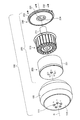
- FIG. 1 is a perspective view showing an appearance of a wheel device incorporating an in-wheel motor according to the present embodiment.
- FIG. 2 is an exploded perspective view showing the configuration of the wheel device incorporating the in-wheel motor according to the present embodiment.
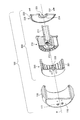
- FIG. 3 is an exploded cross-sectional perspective view showing the configuration of the wheel device incorporating the in-wheel motor according to the present embodiment.
- FIG. 4 is a cross-sectional perspective view showing a configuration of a stator included in the in-wheel motor according to the present embodiment.
- FIG. 5 is an exploded perspective view showing a configuration of a rotor included in the in-wheel motor according to the present embodiment.
- FIG. 6 is a front view showing the wheel device according to the present embodiment.
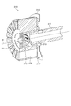
- FIG. 7 is a side sectional view showing the wheel device according to the present embodiment.
- FIG. 1 is a perspective view showing an appearance of a wheel device incorporating an in-wheel motor according to the present embodiment.
- the in-wheel motor which concerns on this embodiment is incorporated in the wheel apparatus 100 shown in FIG. 1, for example.
- the wheel device 100 is used as, for example, a drive wheel of a self-propelled robot or a transport cart.
- the wheel device 100 includes a wheel 110 and a tire 120.
- the wheel 110 is a wheel formed in a substantially bottomed cylindrical shape using metal, plastic, or the like.
- the tire 120 is formed in a substantially annular shape using a material having elasticity such as rubber and is fixed so as to surround the wheel 110.
- the tire 110 is a consumable item, the wheel 110 and the tire 120 have a structure that can be exchanged in an integrated state with each as a basic configuration.
- the in-wheel motor according to the present embodiment is directly connected to the wheel 110 and rotates the wheel 110 about a predetermined rotation axis R. That is, the in-wheel motor according to the present embodiment is, for example, a direct drive type in-wheel motor.
- FIG. 2 is an exploded perspective view showing the configuration of the wheel device 100 incorporating the in-wheel motor according to the present embodiment.
- the in-wheel motor 200 according to the present embodiment is mounted inside the wheel 110 of the wheel device 100 and is fixed to the bottom of the wheel 110 by a nut 111.
- the in-wheel motor 200 includes a stator 210, a rotor 220, and a cover 230.
- the stator 210 is fixed to a device on which the wheel device 100 is mounted via a shaft 211 arranged so as to extend in the axial direction of the rotation axis R.
- the rotor 220 rotates relative to the stator 210 around the rotation axis R.
- the rotor 220 has a casing 221 that accommodates the stator 210, is disposed so as to surround the outer periphery of the stator 210, and rotates along the outer periphery. That is, the in-wheel motor 200 according to the present embodiment is an outer rotor type motor.
- the cover 230 has a through hole 231 formed therein, and seals the space in the housing 221 of the rotor 220 with the shaft 211 passing through the through hole 231.
- the cover 230 is formed in a substantially disc shape, and a through hole 231 is provided in the approximate center.
- the cover 230 is fixed to the wheel 110 with, for example, screws 232 in a state where the stator 210 is housed in the housing 221 and the shaft 211 is passed through the through hole 231.
- the stator 210, the rotor 220, and the in-wheel motor 200 have a waterproof structure that prevents water from entering the casing 221 of the rotor 220.
- the cover 230 includes an O-ring 233 and a rubber seal bearing 234.
- the O-ring 233 is disposed between the cover 230 and the casing 221 of the rotor 220, and seals between the two.
- the rubber seal bearing 234 rotatably supports the shaft 211 inside the through hole 231 of the cover 230 and seals between the through hole 231 and the shaft 211.
- the screw 232 for fixing the cover 230 to the wheel 110 is waterproofed after being tightened.
- FIG. 3 is an exploded cross-sectional perspective view showing the configuration of the wheel device 100 incorporating the in-wheel motor 200 according to the present embodiment.
- the in-wheel motor 200 includes an angle sensor 212 that detects a rotation angle of the rotor 220 with respect to the stator 210.
- the angle sensor 212 is disposed between the axial end portion of the shaft 211 and the portion of the rotor 220 facing the end portion.
- the angle sensor 212 is a magnetic sensor and detects the rotation angle of the rotor 220 with respect to the stator 210 by detecting the angular position of the sensor magnet 222 provided on the stator 210.
- the angle sensor 212 includes an IC (Integrated Circuit), detects an angular position of a magnet placed at a position facing the IC by an absolute angle or a relative angle, and outputs a three-phase control signal for the UVW phase.
- IC Integrated Circuit
- FIG. 4 is a cross-sectional perspective view showing the configuration of the stator 210 provided in the in-wheel motor 200 according to the present embodiment.
- the stator 210 includes a shaft 211, an angle sensor 212, a stator base 213, a bearing 214, a stator core 215, and a substrate 216.
- the stator base 213 is a support member disposed substantially at the center of the stator 210, and is formed in a substantially bottomed cylindrical shape. Here, the stator base 213 is disposed such that the central axis of the stator base 213 coincides with the rotation axis R.
- the shaft 211 is formed in a hollow, substantially cylindrical shape, and is fixed in a state where one end is inserted into the inner peripheral side of the stator base 213.
- the shaft 211 is fixed to the stator base 213 so that the central axis of the shaft 211 coincides with the central axis of the stator base 213.
- the bearing 214 is fixed at a position separated from the outer bottom surface of the stator base 213 by a predetermined distance.
- the bearing 214 is fixed to the stator base 213 so that the center axis of the bearing 214 coincides with the center axis of each of the stator base 213 and the shaft 211.
- the stator core 215 has a laminated structure in which a plurality of plate-like soft magnetic materials are laminated in the axial direction of the stator base 213, and is fixed to the outer periphery of the stator base 213 and the outer periphery of the bearing 214.
- a plurality of salient poles (not shown) are provided on the outer peripheral portion of the stator core 215 at substantially equal intervals along the circumferential direction.
- a coil is wound around each salient pole.
- the substrate 216 is formed in a substantially disc shape and is fixed so as to be orthogonal to the central axis of the stator base 213.
- the substrate 216 is disposed at a predetermined interval in the axial direction along the end surface of the stator core 215 on the side where the shaft 211 protrudes.
- the angle sensor 212 is fixed to the outer bottom surface of the stator base 213 so as to intersect the central axis of the stator base 213. As a result, the angle sensor 212 is disposed at a position facing the bearing hole of the bearing 214.
- the stator 210 further includes another angle sensor 217 that detects the rotation angle of the rotor 220 with respect to the stator 210, in addition to the angle sensor 212 described above.
- another angle sensor 217 that detects the rotation angle of the rotor 220 with respect to the stator 210, in addition to the angle sensor 212 described above.
- the angle sensor 217 an angle sensor using a Hall element or a Hall IC is used.
- three angle sensors 217 are provided on the surface of the substrate 216 on the side facing the stator core 215 by shifting the position by 120 ° in the circumferential direction.
- illustration of two of the three angle sensors 217 is omitted.
- FIG. 5 is an exploded perspective view showing the configuration of the rotor 220 provided in the in-wheel motor 200 according to the present embodiment.
- the rotor 220 includes a housing 221 and a plurality of magnets 223.
- the housing 221 is formed in a substantially bottomed cylindrical shape, and includes a rotor frame 221a serving as a peripheral wall and a rotor case 221b serving as a bottom.
- the rotor frame 221a is formed in a substantially cylindrical shape using a nonmagnetic material.
- the rotor case 221b is formed in a substantially disk shape using a nonmagnetic material.
- the rotor case 221b is provided with a plurality of protrusions 221c that are arranged in a comb shape in the circumferential direction along the end portions and protrude toward the side facing the rotor frame 221a.
- the plurality of magnets 223 each have a strip shape, and are provided in the circumferential direction along the inner circumference of the rotor frame 221a in a magnetized state.
- the protrusions 221c of the rotor case 221b are fitted in the gaps between the magnets 223, so that the positions of the magnets 223 in the circumferential direction of the rotor frame 221a. Fixed.
- these magnets 223 are arranged so as to face the stator core 215 when the stator 210 is incorporated inside the rotor 220. As a result, when a drive current is passed through the coil of the stator core 215, the rotor 220 rotates around the rotation axis R along the outer periphery of the stator 210 by the electromagnetic force generated in the coil.
- the rotor case 221b is provided with a rod-shaped rotor shaft 221d that protrudes along the rotation axis R toward the side facing the rotor frame 221a.
- the aforementioned sensor magnet 222 is fixed to the tip of the rotor shaft 221d.
- the rotor shaft 221d is disposed so as to pass through the bearing hole of the bearing 214 provided in the stator 210 when the stator 210 is incorporated inside the rotor 220.
- the sensor magnet 222 fixed to the tip portion of the rotor shaft 221d is disposed to face the angle sensor 212.
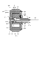
- FIG. 6 is a front view showing the wheel device 100 according to the present embodiment
- FIG. 7 is a side sectional view showing the wheel device 100 according to the present embodiment.
- FIG. 7 shows a cross-section at the position AA of the wheel device 100 shown in FIG.
- the shaft 211 is fixed to the stator 210 and disposed so as to face the rotor 220 with a predetermined distance D in the axial direction.
- the angle sensor 212 is disposed between the axial end portion of the shaft 211 and the portion of the stator 210 facing the end portion.
- stator 210 and the rotor 220 are arranged such that the axial end portion of the shaft 211 on the stator 210 side and the tip end portion of the rotor shaft 221d are spaced apart by a distance D.
- An angle sensor 212 is provided at the end of the shaft 211 on the stator 210 side in the axial direction, and a sensor magnet 222 is provided at the tip of the rotor shaft 221d.
- the distance D is a distance according to the specification of the angle sensor 212.
- the distance D is set so that the sensor magnet 222 is disposed within a range in which the angle sensor 212 can detect the rotation angle. Is done.
- the in-wheel motor 200 can incorporate the angle sensor 212 without increasing the width of the in-wheel motor 200 in the axial direction (stacking direction of the stator core 215).
- such a configuration relating to the arrangement of the magnetic sensor makes it possible to realize an in-wheel motor that can be downsized while incorporating the angle sensor.
- the in-wheel motor 200 is connected to the conductor 241 connected to the stator 210 disposed in the space in the housing 221, the conductor 242 connected to the angle sensor 212, and the angle sensor 217.
- the conducting wire 241 is a power supply line that supplies a driving current to the coil of the stator 210 from an external power supply device.
- the conducting wire 242 is a signal line that transmits a control signal output from the angle sensor 212 to an external control device.
- the conducting wire 243 is a signal line that transmits a control signal output from the angle sensor 217 to an external control device.
- each conducting wire is wired through a through hole 211 a provided in a part of the peripheral wall portion of the shaft 211.
- the through hole 211 a is disposed between the stator core 215 and the cover 230 when the stator 210 is incorporated in the housing 221 and the cover 230 is attached to the housing 221 in the shaft 211. Provided in position.
- each lead wire is passed from the inside of the in-wheel motor 200 to the outside while the space in the housing 221 is kept sealed by the cover 230. Wiring becomes possible.
- the in-wheel motor 200 includes the three angle sensors 217 in addition to the angle sensor 212
- the embodiment is not limited thereto.
- the substrate 216 and the three angle sensors 217 may be omitted from the components of the in-wheel motor 200.
- the in-wheel motor 200 can be further reduced in size.
- the in-wheel motor has been described, but the embodiment is not limited thereto.
- the configuration related to the arrangement of the angle sensor described above can also be applied to other types of motors having a stator and a rotor.
- the outer rotor type motor has been described, but the embodiment is not limited thereto.
- the configuration related to the arrangement of the angle sensor described above can also be applied to an inner rotor type motor and an axial gap type motor.
- an inner rotor type motor includes a stator and a rotor that is disposed on the inner circumference side of the stator and rotates along the inner circumference of the stator.
- the shaft is fixed to the rotor and arranged to face the stator with a predetermined distance in the axial direction.
- the angle sensor is disposed between an axial end portion of the shaft and a portion of the stator facing the end portion.
- an axial gap type motor includes a stator and a rotor arranged to face each other in the axial direction of the rotation shaft.
- the shaft is fixed to one of the stator and the rotor, and is disposed so as to face the other of the stator and the rotor with a predetermined distance in the axial direction.
- the angle sensor is disposed between an axial end portion of the shaft and a portion facing the end portion of the other of the stator and the rotor.
- the angle sensor is arranged inside the motor by placing the end of the shaft in the axial direction and the portion of the stator or rotor facing the end away from each other by a predetermined distance. Space can be secured.
- any type of motor it is possible to incorporate an angle sensor in the motor without increasing the axial width of the motor. That is, it is possible to realize a motor that can be downsized while incorporating an angle sensor.
Landscapes
- Engineering & Computer Science (AREA)
- Chemical & Material Sciences (AREA)
- Combustion & Propulsion (AREA)
- Transportation (AREA)
- Mechanical Engineering (AREA)
- Microelectronics & Electronic Packaging (AREA)
- Power Engineering (AREA)
- Arrangement Or Mounting Of Propulsion Units For Vehicles (AREA)
Abstract
実施形態に係るモータ(200)は、ステータ(210)と、回転軸を中心として前記ステータ(210)に対して相対的に回転するロータ(220)と、前記回転軸の軸方向に延在するように配置されたシャフト(211)と、前記ステータ(210)に対する前記ロータ(220)の回転角度を検出する角度センサー(212)とを備え、前記シャフト(211)は、前記ステータ(210)及び前記ロータ(220)の一方に固定され、前記ステータ(210)及び前記ロータ(220)の他方と前記軸方向に所定の距離だけ離間して対向するように配置され、前記角度センサー(212)は、前記シャフト(211)における前記軸方向の端部と、前記ステータ(210)及び前記ロータ(220)の他方における前記端部と対向する部分との間に配置される。
Description
本発明は、モータ、インホイールモータ及び車輪装置に関する。
従来、各種機器や各種装置の駆動等に用いられるモータには、モータの動作を制御するための角度センサーが設けられるのが一般的である。角度センサーは、モータに含まれるステータとロータとの間の相対的な回転角度を検出する。例えば、角度センサーとしては、光学式エンコーダやレゾルバ等が用いられる。そして、近年では、モータを用いる機器が多様化していることから、角度センサーを内蔵しつつ、小型化されたモータが求められている。
しかしながら、上述した従来の角度センサーを小型のモータに内蔵させることは困難であった。例えば、光学式エンコーダは、耐熱性や形状の問題から、モータに内蔵させることが難しい。また、レゾルバは、コイル等を用いる構造のため小型化することが難しく、小型のモータに内蔵させることは難しい。このようなことから、従来の技術では、角度センサーをモータに内蔵しつつ、小型化されたモータを実現することは困難であった。
本発明は、上記に鑑みてなされたものであって、角度センサーを内蔵しつつ、小型化が可能なモータ、インホイールモータ及び車輪装置を提供することを目的とする。
上述した課題を解決し、目的を達成するために、本発明の一態様に係るモータは、ステータと、回転軸を中心として前記ステータに対して相対的に回転するロータと、前記回転軸の軸方向に延在するように配置されたシャフトと、前記ステータに対する前記ロータの回転角度を検出する角度センサーとを備え、前記シャフトは、前記ステータ及び前記ロータの一方に固定され、前記ステータ及び前記ロータの他方と前記軸方向に所定の距離だけ離間して対向するように配置され、前記角度センサーは、前記シャフトにおける前記軸方向の端部と、前記ステータ及び前記ロータの他方における前記端部と対向する部分との間に配置される。
本発明の一態様によれば、角度センサーを内蔵しつつ、小型化が可能なモータ及びインホイールモータを実現することができる。
以下、図面を参照して、実施形態に係るモータ、インホイールモータ及び車輪装置について説明する。
(実施形態)
図1は、本実施形態に係るインホイールモータを内蔵した車輪装置の外観を示す斜視図である。本実施形態に係るインホイールモータは、例えば、図1に示す車輪装置100に内蔵される。この車輪装置100は、例えば、自走式のロボットや搬送台車等の駆動輪として用いられる。
図1は、本実施形態に係るインホイールモータを内蔵した車輪装置の外観を示す斜視図である。本実施形態に係るインホイールモータは、例えば、図1に示す車輪装置100に内蔵される。この車輪装置100は、例えば、自走式のロボットや搬送台車等の駆動輪として用いられる。
例えば、図1に示すように、車輪装置100は、ホイール110と、タイヤ120とを備える。ホイール110は、金属やプラスチック等を用いて略有底円筒状に形成された車輪である。タイヤ120は、ゴム等の弾力性を有する材料を用いて略円環状に形成され、ホイール110の周りを囲むように固定される。例えば、ホイール110及びタイヤ120は、タイヤ120が消耗品であることから、それぞれを基本構成として、一体化された状態で交換可能な構造とされる。
例えば、本実施形態に係るインホイールモータは、ホイール110に直結され、所定の回転軸Rを中心としてホイール110を回転させる。すなわち、本実施形態に係るインホイールモータは、例えばダイレクトドライブ方式のインホイールモータである。
図2は、本実施形態に係るインホイールモータを内蔵した車輪装置100の構成を示す分解斜視図である。例えば、図2に示すように、本実施形態に係るインホイールモータ200は、車輪装置100のホイール110の内部に搭載され、ナット111によってホイール110の底部に固定される。
例えば、インホイールモータ200は、ステータ210と、ロータ220と、カバー230とを備える。ステータ210は、回転軸Rの軸方向に延在するように配置されたシャフト211を介して、車輪装置100が実装される装置に固定される。
ロータ220は、回転軸Rを中心としてステータ210に対して相対的に回転する。ここで、ロータ220は、ステータ210を収容する筐体221を有し、ステータ210の外周を囲むように配置され、当該外周に沿って回転する。すなわち、本実施形態に係るインホイールモータ200は、アウターロータ形のモータである。
カバー230は、貫通孔231が形成され、当該貫通孔231にシャフト211を貫通させた状態で、ロータ220の筐体221内の空間を密閉する。例えば、カバー230は、略円板状に形成され、略中央に貫通孔231が設けられる。そして、カバー230は、筐体221内にステータ210が収容され、かつ、貫通孔231にシャフト211を貫通させた状態で、例えばねじ232によってホイール110に固定される。
ここで、ステータ210、ロータ220及びインホイールモータ200は、ロータ220の筐体221内への水の浸入を防ぐ防水構造とされている。例えば、カバー230は、Oリング233と、ゴムシールベアリング234とを備える。Oリング233は、カバー230と、ロータ220の筐体221との間に配置され、両者の間を密閉する。ゴムシールベアリング234は、カバー230の貫通孔231の内側でシャフト211を回転可能に支持するとともに、貫通孔231とシャフト211との間を密閉する。また、カバー230をホイール110に固定するねじ232は、締め付け後に防水加工が施される。
図3は、本実施形態に係るインホイールモータ200を内蔵した車輪装置100の構成を示す分解断面斜視図である。例えば、図3に示すように、インホイールモータ200は、ステータ210に対するロータ220の回転角度を検出する角度センサー212を備える。ここで、角度センサー212は、シャフト211における軸方向の端部と、ロータ220における当該端部と対向する部分との間に配置される。
本実施形態では、角度センサー212は、磁気センサーであり、ステータ210に設けられ、ロータ220に設けられたセンサー用磁石222の角度位置を検出することで、ステータ210に対するロータ220の回転角度を検出する。例えば、この角度センサー212としては、IC(Integrated Circuit)を備え、当該ICと対向する位置に置かれた磁石の角度位置を絶対角又は相対角で検出し、UVW相の3相の制御信号を出力可能な高速回転角度センサーが用いられる。
図4は、本実施形態に係るインホイールモータ200が備えるステータ210の構成を示す断面斜視図である。例えば、図4に示すように、ステータ210は、シャフト211と、角度センサー212と、ステータベース213と、ベアリング214と、ステータコア215と、基板216とを備える。
ステータベース213は、ステータ210の略中央に配置される支持部材であり、略有底円筒状に形成される。ここで、ステータベース213は、当該ステータベース213の中心軸が回転軸Rと一致するように配置される。
シャフト211は、中空の略円筒状に形成され、一方の端部がステータベース213の内周側に挿入された状態で固定される。ここで、シャフト211は、当該シャフト211の中心軸がステータベース213の中心軸と一致するように、ステータベース213に固定される。
ベアリング214は、ステータベース213の外底面から所定の距離だけ離間した位置に固定される。ここで、ベアリング214は、当該ベアリング214の中心軸がステータベース213及びシャフト211それぞれの中心軸と一致するように、ステータベース213に固定される。
ステータコア215は、複数の板状の軟磁性材料をステータベース213の軸方向に積層した積層構造を有し、ステータベース213の外周及びベアリング214の外周側に固定される。ここで、ステータコア215の外周部分には、周方向に沿って略均等な間隔で複数の突極(図示せず)が設けられている。そして、各突極には、コイルが巻回されている。
基板216は、略円板状に形成され、ステータベース213の中心軸と直交するように固定される。ここで、基板216は、ステータコア215におけるシャフト211が突出した側の端面に沿って、軸方向に所定の間隔を空けて配置される。
そして、本実施形態では、ステータベース213の外底面に、ステータベース213の中心軸と交差するように角度センサー212が固定される。これにより、角度センサー212は、ベアリング214の軸受孔と対向する位置に配置されることになる。
また、本実施形態では、ステータ210は、上述した角度センサー212とは別に、ステータ210に対するロータ220の回転角度を検出する他の角度センサー217をさらに備える。例えば、この角度センサー217としては、ホール素子又はホールICを用いた角度センサーが用いられる。
例えば、基板216のステータコア215と対向する側の面上に、周方向に120°ずつ位置をずらして3つの角度センサー217が設けられる。なお、図4では、3つの角度センサー217のうちの2つについては図示を省略している。
このように、角度センサーを複数設けた冗長構成とすることが可能になる。
図5は、本実施形態に係るインホイールモータ200が備えるロータ220の構成を示す分解斜視図である。例えば、図5に示すように、ロータ220は、筐体221と、複数の磁石223とを備える。
筐体221は、略有底円筒状に形成され、周壁となるロータフレーム221aと、底部となるロータケース221bとを備える。ロータフレーム221aは、非磁性材料を用いて略円筒状に形成される。ロータケース221bは、非磁性材料を用いて略円板状に形成される。ロータケース221bには、端部に沿って周方向に櫛歯状に並び、かつ、それぞれロータフレーム221aと対向する側に向けて突出する複数の突起部221cが設けられる。
複数の磁石223は、それぞれ短冊状の形状を有し、着磁済みの状態で、ロータフレーム221aの内周に沿って周方向に略均等な間隔で設けられる。これらの磁石223は、ロータフレーム221aにロータケース221bが取り付けられた際に、ロータケース221bの各突起部221cが各磁石223の間隙に嵌合することによって、ロータフレーム221aにおける周方向の位置が固定される。
また、これらの磁石223は、ロータ220の内側にステータ210が組み込まれた際に、ステータコア215と対向するように配置される。これにより、ステータコア215のコイルに駆動電流が流された際に、コイルに発生する電磁力によって、ロータ220が回転軸Rを中心としてステータ210の外周に沿って回転する。
そして、本実施形態では、ロータケース221bに、回転軸Rに沿ってロータフレーム221aと対向する側に向けて突出する棒状のロータ軸221dが設けられる。ここで、ロータ軸221dの先端部分には、前述したセンサー用磁石222が固定される。このロータ軸221dは、ロータ220の内側にステータ210が組み込まれた際に、ステータ210に設けられたベアリング214の軸受孔を貫通するように配置される。これにより、ロータ軸221dの先端部分に固定されたセンサー用磁石222が、角度センサー212と対向して配置されることになる。
図6は、本実施形態に係る車輪装置100を示す正面図であり、図7は、本実施形態に係る車輪装置100を示す側面断面図である。なお、図7は、図6に示す車輪装置100の位置A-Aにおける断面を示している。
例えば、図7に示すように、本実施形態では、シャフト211が、ステータ210に固定され、軸方向に所定の距離Dだけ離間してロータ220と対向するように配置される。そして、角度センサー212が、シャフト211における軸方向の端部と、ステータ210における当該端部と対向する部分との間に配置される。
具体的には、シャフト211における軸方向のステータ210側の端部と、ロータ軸221dの先端部分とが距離Dだけ離間して配置されるように、ステータ210及びロータ220が配置される。そして、シャフト211における軸方向のステータ210側の端部に角度センサー212が設けられ、ロータ軸221dの先端部分にセンサー用磁石222が設けられる。
ここで、距離Dは、角度センサー212の仕様に応じた距離とされる。例えば、本実施形態のように角度センサー212として磁気センサーが用いられる場合には、角度センサー212によって回転角度の検出が可能な範囲内にセンサー用磁石222が配置されるように、距離Dが設定される。
このように、シャフト211の軸方向の端部とロータ220とを所定の距離Dだけ離間して配置することによって、インホイールモータ200の内部に、角度センサー212を配置するための空間を確保することができる。これにより、インホイールモータ200の軸方向(ステータコア215の積層方向)の幅を拡げることなく、インホイールモータ200に角度センサー212を内蔵させることが可能になる。本実施形態では、このような磁気センサーの配置に関する構成によって、角度センサーを内蔵しつつ、小型化が可能なインホイールモータを実現することが可能になる。
また、本実施形態では、インホイールモータ200は、筐体221内の空間に配置されたステータ210に接続される導線241と、角度センサー212に接続される導線242と、角度センサー217に接続される導線243とを備える。
ここで、導線241は、ステータ210のコイルに外部の電源装置から駆動電流を供給する給電線である。また、導線242は、角度センサー212から出力される制御信号を外部の制御装置に伝送する信号線である。また、導線243は、角度センサー217から出力される制御信号を外部の制御装置に伝送する信号線である。
そして、導線241~243は、筐体221内の空間からシャフト211の内部を通ってカバー230の外へ配線される。例えば、各導線は、シャフト211における周壁部分の一部に設けられた貫通孔211aを通して配線される。ここで、貫通孔211aは、シャフト211において、筐体221内にステータ210が組み込まれ、かつ、筐体221にカバー230が取り付けられた際に、ステータコア215とカバー230との間に配置される位置に設けられる。
このように、シャフト211の内部を通って各導線を配線することによって、カバー230によって筐体221内の空間が密閉された状態を保ったまま、インホイールモータ200の内部から外部へ各導線を配線することが可能になる。
上述したように、本実施形態によれば、角度センサーを内蔵しつつ、小型化が可能なインホイールモータを実現することができる。
なお、上述した実施形態では、インホイールモータ200が、角度センサー212の他に3つの角度センサー217を備える場合の例を説明したが、実施形態はこれに限られない。例えば、角度検出用のセンサーが角度センサー212だけで足りる場合には、インホイールモータ200の構成要素から、基板216及び3つの角度センサー217を除いてもよい。この場合には、基板216及び3つの角度センサー217を除いた分だけ、ステータ210の軸方向の幅をより短くすることができるので、インホイールモータ200をさらに小型化することができる。
また、上述した実施形態では、インホイールモータについて説明したが、実施形態はこれに限られない。ステータ及びロータを有する他の種類のモータについても、上述した角度センサーの配置に関する構成が適用可能である。
また、上述した実施形態では、アウターロータ形のモータについて説明したが、実施形態はこれに限られない。例えば、インナーロータ形のモータやアキシャルギャップ形のモータについても、上述した角度センサーの配置に関する構成が適用可能である。
例えば、インナーロータ形のモータは、ステータと、ステータの内周側に配置され、ステータの内周に沿って回転するロータとを備える。この場合に、例えば、シャフトは、ロータに固定され、ステータと軸方向所定の距離だけ離間して対向するように配置される。そして、角度センサーは、シャフトにおける軸方向の端部と、ステータにおける当該端部と対向する部分との間に配置される。
また、例えば、アキシャルギャップ形のモータは、回転軸の軸方向に対向して配置されたステータ及びロータを備える。この場合には、例えば、シャフトは、ステータ及びロータの一方に固定され、ステータ及びロータの他方と軸方向に所定の距離だけ離間して対向するように配置される。そして、角度センサーは、シャフトにおける軸方向の端部と、ステータ及びロータの他方における当該端部と対向する部分との間に配置される。
いずれの種類のモータでも、シャフトの軸方向における端部と、ステータ又はロータにおける当該端部と対向する部分とを所定の距離だけ離間して配置することによって、モータの内部に、角度センサーを配置するための空間を確保することができる。これにより、いずれの種類のモータでも、モータの軸方向の幅を拡げることなく、モータに角度センサーを内蔵させることが可能になる。すなわち、角度センサーを内蔵しつつ、小型化が可能なモータを実現することができる。
また、上記実施の形態により本発明が限定されるものではない。上述した各構成素を適宜組み合わせて構成したものも本発明に含まれる。また、さらなる効果や変形例は、当業者によって容易に導き出すことができる。よって、本発明のより広範な態様は、上記の実施の形態に限定されるものではなく、様々な変更が可能である。
110 ホイール
200 インホイールモータ
210 ステータ
211 シャフト
212 角度センサー
217 角度センサー
220 ロータ
221 筐体
222 センサー用磁石
230 カバー
241~243 導線
200 インホイールモータ
210 ステータ
211 シャフト
212 角度センサー
217 角度センサー
220 ロータ
221 筐体
222 センサー用磁石
230 カバー
241~243 導線
Claims (7)
- ステータと、
回転軸を中心として前記ステータに対して相対的に回転するロータと、
前記回転軸の軸方向に延在するように配置されたシャフトと、
前記ステータに対する前記ロータの回転角度を検出する角度センサーと
を備え、
前記シャフトは、前記ステータ及び前記ロータの一方に固定され、前記ステータ及び前記ロータの他方と前記軸方向に所定の距離だけ離間して対向するように配置され、
前記角度センサーは、前記シャフトにおける前記軸方向の端部と、前記ステータ及び前記ロータの他方における前記端部と対向する部分との間に配置される、
モータ。 - 前記角度センサーとは別に、前記ステータに対する前記ロータの回転角度を検出する他の角度センサーをさらに備える、
請求項1に記載のモータ。 - 前記ステータ及び前記ロータの一方を収容する筐体と、
貫通孔が形成され、当該貫通孔に前記シャフトを貫通させた状態で、前記筐体内の空間を密閉するカバーと、
前記ステータ及び前記ロータの一方、又は、前記角度センサーに接続される導線と
をさらに備え、
前記導線は、前記筐体内の空間から前記シャフトの内部を通って前記カバーの外へ配線される、
請求項1又は2に記載のモータ。 - 前記角度センサーは、前記ロータ及び前記ステータの一方に設けられ、前記ロータ及び前記ステータの他方に設けられたセンサー用磁石の角度位置を検出することで、前記回転角度を検出する磁気センサーである、
請求項1又は2に記載のモータ。 - 前記ロータは、前記ステータの外周を囲むように配置され、当該外周に沿って回転する、
請求項1又は2に記載のモータ。 - ホイールの内部に搭載されるインホイールモータであって、
ステータと、
回転軸を中心として前記ステータに対して相対的に回転するロータと、
前記回転軸の軸方向に延在するように配置されたシャフトと、
前記ステータに対する前記ロータの回転角度を検出する角度センサーと
を備え、
前記シャフトは、前記ステータに固定され、前記軸方向に所定の距離だけ離間して前記ロータと対向するように配置され、
前記角度センサーは、前記シャフトにおける前記軸方向の端部と、前記ロータにおける前記端部と対向する部分との間に配置される、
インホイールモータ。 - 請求項1に記載のモータ又は請求項6に記載のインホイールモータを内蔵した車輪装置。
Applications Claiming Priority (2)
| Application Number | Priority Date | Filing Date | Title |
|---|---|---|---|
| JP2016078317A JP6842838B2 (ja) | 2016-04-08 | 2016-04-08 | モータ、インホイールモータ及び車輪装置 |
| JP2016-078317 | 2016-04-08 |
Publications (1)
| Publication Number | Publication Date |
|---|---|
| WO2017175609A1 true WO2017175609A1 (ja) | 2017-10-12 |
Family
ID=60000367
Family Applications (1)
| Application Number | Title | Priority Date | Filing Date |
|---|---|---|---|
| PCT/JP2017/012108 Ceased WO2017175609A1 (ja) | 2016-04-08 | 2017-03-24 | モータ、インホイールモータ及び車輪装置 |
Country Status (2)
| Country | Link |
|---|---|
| JP (1) | JP6842838B2 (ja) |
| WO (1) | WO2017175609A1 (ja) |
Cited By (2)
| Publication number | Priority date | Publication date | Assignee | Title |
|---|---|---|---|---|
| WO2020066960A1 (ja) * | 2018-09-28 | 2020-04-02 | 本田技研工業株式会社 | モータの構造 |
| CN110971086A (zh) * | 2018-09-28 | 2020-04-07 | 本田技研工业株式会社 | 马达的构造 |
Families Citing this family (5)
| Publication number | Priority date | Publication date | Assignee | Title |
|---|---|---|---|---|
| JP7302231B2 (ja) * | 2019-03-28 | 2023-07-04 | ニデック株式会社 | モータ |
| KR102224049B1 (ko) * | 2019-08-23 | 2021-03-08 | 효림산업 주식회사 | 차량용 인휠 모터 |
| KR102694038B1 (ko) * | 2019-12-30 | 2024-08-12 | 엘지전자 주식회사 | 인휠모터 |
| JPWO2024062870A1 (ja) * | 2022-09-22 | 2024-03-28 | ||
| KR102847889B1 (ko) * | 2022-11-29 | 2025-08-19 | 엘지전자 주식회사 | 로봇 휠 구동장치 |
Citations (6)
| Publication number | Priority date | Publication date | Assignee | Title |
|---|---|---|---|---|
| US5894902A (en) * | 1996-09-05 | 1999-04-20 | The United States Of America As Represented By The Secretary Of The Navy | Self-propelled wheel for wheeled vehicles |
| JP3094345B2 (ja) * | 1991-10-29 | 2000-10-03 | 東京電力株式会社 | ホイールモータ |
| JP2004343905A (ja) * | 2003-05-16 | 2004-12-02 | Toyota Motor Corp | モータ内蔵車輪装置 |
| WO2010038862A1 (ja) * | 2008-10-03 | 2010-04-08 | 日本電産株式会社 | モータ |
| WO2011111617A1 (ja) * | 2010-03-10 | 2011-09-15 | Ntn株式会社 | 電気自動車のモータ駆動システム |
| JP2014168344A (ja) * | 2013-02-28 | 2014-09-11 | Honda Motor Co Ltd | クランク軸の位置検出構造 |
Family Cites Families (3)
| Publication number | Priority date | Publication date | Assignee | Title |
|---|---|---|---|---|
| JP5517869B2 (ja) * | 2009-11-27 | 2014-06-11 | Ntn株式会社 | インホイール型モータ内蔵センサ付き車輪用軸受装置 |
| JP5615033B2 (ja) * | 2010-05-17 | 2014-10-29 | Ntn株式会社 | インホイールモータ駆動装置 |
| JP2015089188A (ja) * | 2013-10-29 | 2015-05-07 | Ntn株式会社 | インホイールモータおよびインホイールモータ駆動装置 |
-
2016
- 2016-04-08 JP JP2016078317A patent/JP6842838B2/ja active Active
-
2017
- 2017-03-24 WO PCT/JP2017/012108 patent/WO2017175609A1/ja not_active Ceased
Patent Citations (6)
| Publication number | Priority date | Publication date | Assignee | Title |
|---|---|---|---|---|
| JP3094345B2 (ja) * | 1991-10-29 | 2000-10-03 | 東京電力株式会社 | ホイールモータ |
| US5894902A (en) * | 1996-09-05 | 1999-04-20 | The United States Of America As Represented By The Secretary Of The Navy | Self-propelled wheel for wheeled vehicles |
| JP2004343905A (ja) * | 2003-05-16 | 2004-12-02 | Toyota Motor Corp | モータ内蔵車輪装置 |
| WO2010038862A1 (ja) * | 2008-10-03 | 2010-04-08 | 日本電産株式会社 | モータ |
| WO2011111617A1 (ja) * | 2010-03-10 | 2011-09-15 | Ntn株式会社 | 電気自動車のモータ駆動システム |
| JP2014168344A (ja) * | 2013-02-28 | 2014-09-11 | Honda Motor Co Ltd | クランク軸の位置検出構造 |
Cited By (5)
| Publication number | Priority date | Publication date | Assignee | Title |
|---|---|---|---|---|
| WO2020066960A1 (ja) * | 2018-09-28 | 2020-04-02 | 本田技研工業株式会社 | モータの構造 |
| CN110971086A (zh) * | 2018-09-28 | 2020-04-07 | 本田技研工业株式会社 | 马达的构造 |
| JP2020058087A (ja) * | 2018-09-28 | 2020-04-09 | 本田技研工業株式会社 | モータの構造 |
| CN112771768A (zh) * | 2018-09-28 | 2021-05-07 | 本田技研工业株式会社 | 马达的结构 |
| JP7156892B2 (ja) | 2018-09-28 | 2022-10-19 | 本田技研工業株式会社 | モータの構造 |
Also Published As
| Publication number | Publication date |
|---|---|
| JP6842838B2 (ja) | 2021-03-17 |
| JP2017185975A (ja) | 2017-10-12 |
Similar Documents
| Publication | Publication Date | Title |
|---|---|---|
| JP6842838B2 (ja) | モータ、インホイールモータ及び車輪装置 | |
| CN205489998U (zh) | 马达 | |
| JP6511137B2 (ja) | ブラシレスモータ | |
| TW201826670A (zh) | 馬達 | |
| US20030230945A1 (en) | Brushless motor | |
| JP2010104212A (ja) | ブラシレスモータ | |
| KR20170082573A (ko) | 회전각 검출 장치 및 파워 스티어링 장치 | |
| US20080174212A1 (en) | Brushless Electric Motor | |
| CA2566542A1 (en) | Brushless dc motors with remote hall sensing and methods of making the same | |
| WO2017033917A1 (ja) | モータ | |
| WO2016068073A1 (ja) | 駆動装置 | |
| JPWO2020137291A1 (ja) | モータ | |
| JP4753545B2 (ja) | トルク検出装置及びこれの製造方法 | |
| CN103944344A (zh) | 4极无刷直流电机位置传感器及其检测方法 | |
| JP5566470B2 (ja) | 電動パワーステアリング用モータ | |
| JP2013090501A (ja) | モータ | |
| JPWO2019038849A1 (ja) | 電動駆動装置 | |
| JP2005160296A (ja) | ロータ位置を検出するセンサを備えた電気モータ | |
| JP2014236531A (ja) | モータ | |
| JP2010124519A (ja) | 電動モータ | |
| KR102516543B1 (ko) | 모터 및 이를 포함하는 전동식 조향장치 | |
| WO2020166344A1 (ja) | モータ装置 | |
| JP2008079468A (ja) | ブラシレスモータ | |
| JP5538660B2 (ja) | 回転電機 | |
| KR101396175B1 (ko) | 브러시레스 직류모터 |
Legal Events
| Date | Code | Title | Description |
|---|---|---|---|
| NENP | Non-entry into the national phase |
Ref country code: DE |
|
| 121 | Ep: the epo has been informed by wipo that ep was designated in this application |
Ref document number: 17778988 Country of ref document: EP Kind code of ref document: A1 |
|
| 122 | Ep: pct application non-entry in european phase |
Ref document number: 17778988 Country of ref document: EP Kind code of ref document: A1 |