WO2017175456A1 - 混練機構、造型装置及び発泡混合物の製造方法 - Google Patents
混練機構、造型装置及び発泡混合物の製造方法 Download PDFInfo
- Publication number
- WO2017175456A1 WO2017175456A1 PCT/JP2017/003001 JP2017003001W WO2017175456A1 WO 2017175456 A1 WO2017175456 A1 WO 2017175456A1 JP 2017003001 W JP2017003001 W JP 2017003001W WO 2017175456 A1 WO2017175456 A1 WO 2017175456A1
- Authority
- WO
- WIPO (PCT)
- Prior art keywords
- air
- air supply
- stirring
- frame
- tank
- Prior art date
- Legal status (The legal status is an assumption and is not a legal conclusion. Google has not performed a legal analysis and makes no representation as to the accuracy of the status listed.)
- Ceased
Links
Images


Classifications
-
- B—PERFORMING OPERATIONS; TRANSPORTING
- B22—CASTING; POWDER METALLURGY
- B22C—FOUNDRY MOULDING
- B22C5/00—Machines or devices specially designed for dressing or handling the mould material so far as specially adapted for that purpose
- B22C5/04—Machines or devices specially designed for dressing or handling the mould material so far as specially adapted for that purpose by grinding, blending, mixing, kneading, or stirring
-
- B—PERFORMING OPERATIONS; TRANSPORTING
- B22—CASTING; POWDER METALLURGY
- B22C—FOUNDRY MOULDING
- B22C15/00—Moulding machines characterised by the compacting mechanism; Accessories therefor
- B22C15/02—Compacting by pressing devices only
Definitions
- the present invention relates to a kneading mechanism, a molding apparatus, and a method for producing a foamed mixture.
- the present invention is intended to obtain a kneading mechanism, a molding apparatus, and a method for producing a foamed mixture that can shorten the time required to obtain a foamed mixture having good fluidity in consideration of the above facts.
- the kneading mechanism of the first aspect of the present invention includes a stirring tank for storing the particulate aggregate and the additive, a stirring blade for stirring the additive containing the particulate aggregate and the foaming agent in the stirring tank, An air supply port is formed in the stirring blade, and an air supply mechanism capable of supplying air from the air supply port into the stirring tank.
- the particulate aggregate and additive stored in the stirring tank are stirred by the stirring blade.
- an air supply port is formed in the stirring blade, and the air supply mechanism can supply air from the air supply port into the stirring tank.
- Air can be included. Therefore, compared with the case where air is not supplied from a stirring blade, a foaming mixture with good fluidity can be obtained by stirring for a short time.
- the kneading mechanism according to the second aspect of the present invention is the structure according to the first aspect, wherein the stirring blade is a frame having a hollow cross-section, and the frame through which the air flows, and the frame. And an air supply port formed at a portion facing the frame inside of the frame body.
- the stirring blade is a frame body and includes the frame body through which the air flows through the hollow portion and the net portion disposed inside the frame.
- the mixture of the particulate aggregate and the additive to be passed through can be finely divided by a mesh portion so that air can be included in the mixture.
- the air supply port is formed at the part facing the inner side of the frame having a hollow cross-section, air is blown into the mixture that passes through the inner side of the frame, so that the mixture being stirred Air can be contained more efficiently.
- the stirring blade is a frame having a hollow cross-section, the frame through which the air flows, and the frame. And a net portion disposed on the inner side of the frame body, and the air at a portion facing the side opposite to the side on which the frame body rotates when the rotating shaft rotates.
- a supply port is formed.
- the stirring blade is a frame body and includes the frame body through which the air flows through the hollow portion and the net portion disposed inside the frame.
- the mixture of the particulate aggregate and the additive to be passed through can be finely divided by a mesh portion so that air can be included in the mixture.
- the frame having a hollow cross-section is attached to a rotating shaft that rotates in a predetermined rotation direction, and the frame has a portion that faces away from the side on which the frame rotates when the rotating shaft rotates. An air supply port is formed. For this reason, at the time of stirring by the stirring blade, turbulent flow is generated in a region opposite to the side on which the frame body rotates and air is blown into the region where such turbulent flow is generated. Air can be efficiently contained.
- the air supplied to the stirring tank is supplied to the air flow passage of the air supply mechanism.
- a humidifying mechanism for humidifying is provided.
- the humidification mechanism provided in the air flow path of the air supply mechanism humidifies the air supplied into the stirring tank. Then, when the air is supplied from the air supply port into the stirring tank while the particulate aggregate and the additive are being stirred by the stirring blade, the mixture of the particulate aggregate and the additive is added to the air. Moisture will be supplied. For this reason, for example, even in an environment where the initial moisture ratio of the mixture in the stirring tank is suppressed and the mixture being stirred is easily dried, the drying of the mixture is suppressed without replenishing water separately. And foaming proceeds stably.
- the axis is set along the vertical direction, and the stirring blade is attached to the lower end portion.
- a rotating shaft arranged to be rotatable around its own axis, a tube through which the air supplied from the air supply port into the stirring tank passes, and an upper end portion of the rotating shaft.
- a joint portion that covers from above and is connected to the rotation shaft via a bearing disposed on the outer peripheral side of the upper end portion of the rotation shaft, and the tube includes a lower portion and a side portion of the joint portion. It is arranged in a state of passing through the joint part and supported by the side part of the joint part.
- the rotating shaft with which the stirring blade was attached to the lower end part is arrange
- the joint part which covers the upper end part of a rotating shaft from upper direction is the upper end of a rotating shaft. It is connected to the rotating shaft via a bearing arranged on the outer peripheral side of the part. For this reason, even if the rotating shaft rotates around its own axis, the joint portion does not rotate.
- the tube that circulates the air supplied from the air supply port into the agitation tank passes through the inside of the rotating shaft, but the tube passes through the joint part through the lower part and the side part of the joint part. Since it is supported by the side part of the joint part, the position where the joint part supports the tube is maintained even if the tube rotates together with the rotating shaft. Thereby, it can prevent that a tube becomes entangled at the time of rotation of a rotating shaft.
- a pressure sensor is disposed in the air flow passage of the air supply mechanism.
- the detected value of the pressure sensor becomes higher than when the air supply port is not clogged. Can be detected.
- the diameter of the air supply port is set to 0.1 mm to 0.3 mm.
- the pressure loss can be suppressed by making the diameter of the air supply port 0.1 mm or more, and the air can be blown out favorably, and the diameter of the air supply port is 0.3 mm or less.
- the diameter of the air supply port is 0.3 mm or less.
- a molding apparatus in which a mold molding space is formed by one mold and the other mold, and a filling opening is formed through an upper wall portion disposed on the upper side.
- a filling port is formed through the bottom of the agitation tank, and the agitation tank is capable of agitating the particulate aggregate and additive in the agitation tank by the agitation blade;
- the kneading mechanism according to any one of the first to third aspects, which is arranged so as to be movable between the second position which is directly above the filling port, and the state where the kneading mechanism is arranged at the first position.
- a filling port closing mechanism for closing the filling port of the agitation tank, a material supply unit for supplying an additive containing particulate aggregate and a foaming agent to the agitation tank arranged in the first position, A pressing mechanism that presses the contents of the agitation tank in the second position from above. That.
- the filling port at the bottom of the agitation tank is closed by the filling port closing mechanism, and the particulate aggregate and additive are supplied from the material supply unit to the agitation tank. Supplied.
- air is supplied from the air supply port into the stirring tank while the additive containing the particulate aggregate and the foaming agent in the stirring tank is stirred by the stirring blade, the particulate aggregate and the additive Air can be efficiently contained therein, and a foamed mixture having good fluidity can be obtained by stirring for a short time.
- the foamed mixture as the contents of the stirring tank is moved upward by the pressing mechanism. Is pressed from. Thereby, after passing through the filling port and the filling port, the foamed mixture is filled into a mold making space formed by one mold and the other mold and solidified to form a mold.
- the method for producing a foamed mixture according to the ninth aspect of the present invention includes a stirring tank, a stirring blade for stirring the contents of the stirring tank, an air supply port formed in the stirring blade, and the stirring from the air supply port.
- the air is supplied into the stirring tank by the air supply mechanism from the air supply port formed in the stirring blade. Supply.
- air can be efficiently contained in the mixture of the particulate aggregate and the additive, so that the foaming has good fluidity with short stirring compared to the case where air is not supplied from the stirring blade. A mixture can be obtained.
- the method for producing a foamed mixture according to a tenth aspect of the present invention is the structure according to the first aspect, wherein the air supply mechanism humidifies the air and then supplies the air from the air supply port into the stirring tank. To do.
- air can be efficiently contained in the particulate aggregate and additive, and the time required to obtain a foamed mixture having good fluidity can be shortened. It has an excellent effect of being able to.
- FIG. 4A shows the result of kinematic viscosity measurement.
- FIG. 4B shows the result of moisture measurement. It is a figure which shows the flow of experiment. It is a figure which shows the principal part of a modification.
- FIG. 6A shows a front view.
- FIG. 6B is a schematic plan view of the frame.
- FIG. 1 shows a schematic front view of a molding apparatus 10 according to the present embodiment. Note that up, down, left and right mean up, down, left and right in the figure unless otherwise specified or apparent in context.
- the molding apparatus 10 has a kneading mechanism 12 on the right side of the apparatus.
- the kneading mechanism 12 includes a stirring tank 20 (also referred to as “kneading tank”) that stores sand and additives as particulate aggregates, and stirs the contents (sand and additives) in the stirring tank 20.
- a stirring blade 24 (also referred to as “kneading blade”) is provided as a stirring blade.
- a plurality of filling ports 22 are formed through the bottom 20B of the stirring tank 20 in a container shape, and a filling port closing mechanism 26 that can close the filling port 22 is provided below the stirring tank 20 in the figure. It has been.
- the kneading mechanism 12 includes a use position (position shown in FIG. 1) where the stirring blade 24 is positioned inside the stirring tank 20, and a retreat position (not shown) where the stirring blade 24 is retracted upward from the inside of the stirring tank 20. , And a kneading blade moving mechanism 28 that moves between them (in the direction of arrow Y).
- the kneading mechanism 12 includes at least a foaming agent as an additive and kneads a foamable sand mold material. Typically, including but not limited to a water-soluble binder and water, other additives may also be included.
- the molding apparatus 10 further includes a horizontal movement mechanism 32 for moving the stirring tank 20 of the kneading mechanism 12 along the frame portion 30 extending in the left-right direction (in the direction of the arrow X).
- the horizontal movement mechanism 32 is a kneading position as the first position on the lower side of the stirring blade 24 (the same position as the position shown in FIG. 1) with the stirring blade 24 in the retracted position. ) And a filling position (not shown) as a second position on the left side of the apparatus with respect to the kneading position.
- the kneading position is set to a position where the sand and additives in the stirring tank 20 can be stirred by the stirring blade 24, and both the filling positions are between the mold 40 and the pressing mechanism 16 described later. Set to position.
- the molding apparatus 10 has a mold mechanism 14 on the left side of the apparatus and on the lower side of the apparatus with respect to the kneading mechanism 12.
- the mold mechanism 14 includes a mold 40 for forming the foamed mixture kneaded by the kneading mechanism 12 into a predetermined shape.
- a pressing mechanism 16 (filling mechanism) is provided immediately above the mold mechanism 14 and in the upper part of the apparatus. The pressing mechanism 16 presses the foamed mixture, which is the content of the stirring tank 20 in a state where the stirring tank 20 is disposed at the filling position (not shown), from above, and from the filling port 22 of the stirring tank 20.
- the mold 40 is configured to be filled (injected) with the foamed mixture.
- a mold extrusion mechanism 18 (upper mold extrusion mechanism) is provided on the left side of the stirring tank 20 on the apparatus upper side with respect to the mold mechanism 14 and on the apparatus lower side with respect to the pressing mechanism 16.
- the mold extrusion mechanism 18 is a mechanism for taking out the mold from the mold 40 by opening the mold 40 in conjunction with the mold mechanism 14.
- the mold extrusion mechanism 18 is connected to the stirring tank 20 via the connecting portion 19 in the apparatus left-right direction, and can be moved together with the stirring tank 20 in the apparatus left-right direction.
- the mold 40 forms a mold making space with an upper mold 42 as one mold and a lower mold 44 as the other mold. That is, the mold 40 in the present embodiment is a horizontal split mold.
- the lower mold 44 is attached to the upper surface of the lifting frame 14A.
- the elevating frame 14A can be moved up and down along guide rods 14C erected in the vertical direction of the apparatus at the four corners of the machine base 14B, and the piston rod of the cylinder 14D installed upward on the lower side of the elevating frame 14A. 14D1. That is, the elevating frame 14A is raised and lowered according to the expansion and contraction of the piston rod 14D1 of the cylinder 14D.
- the upper die 42 is disposed immediately above the lower die 44 and is supported by a support mechanism portion 14E attached to the guide rod 14C. Further, a filling port 46 is formed through the upper wall portion 42A of the upper mold 42 (the upper wall portion disposed on the upper side of the mold 40).
- the pressing mechanism 16 provided in the upper part of the apparatus just above the mold mechanism 14 is provided in the ceiling part 30A of the frame part 30 and includes a piston 16A.
- a plurality of exhaust holes (not shown) are formed through the piston 16A.
- the piston 16A is connected to the lower end side of the piston rod 16B1 of the downward cylinder 16B, and moves up and down by the operation of the cylinder 16B.
- the mold extruding mechanism 18 provided on the apparatus left side of the stirring tank 20 on the lower side of the apparatus with respect to the pressing mechanism 16 includes a mold extruding member 18A.
- a plurality of mold extruding pins are formed in the mold extruding member 18A, and these mold extruding pins can be inserted into a filling port 46 formed in the upper mold 42.
- the mold extruding member 18A is connected to the lower end side of the piston rod 18B1 of the downward cylinder 18B, and moves up and down by the operation of the cylinder 18B.
- a horizontal movement mechanism 32 for moving the agitation tank 20 and the mold pushing mechanism 18 in the left-right direction of the apparatus includes a guide part 32A extending in the left-right direction of the apparatus in the frame part 30, and a traveling carriage capable of traveling along the guide part 32A. (Not shown). That is, the horizontal movement mechanism 32 moves the stirring tank 20 and the mold extrusion mechanism 18 as the traveling carriage travels (moves) along the guide portion 32A.
- the frame part 30 is being fixed to the upper end part of the guide rod 14C mentioned above.
- the filling position (not shown) of the stirring tank 20 is a position where the filling port 22 of the stirring tank 20 is directly above the filling port 46 of the upper mold 42.
- a state where the mold pushing mechanism 18 is disposed at a position retracted from right above the mold 40 to the left side of the apparatus is indicated by a two-dot chain line.
- the kneading mechanism 12 includes the stirring tank 20 as described above.
- the agitation tank 20 includes a cylindrical portion 20A having the vertical direction as the central axis direction, and a bottom portion 20B that is fixed to the lower end of the cylindrical portion 20A and closes the lower end side opening of the cylindrical portion 20A.
- the volume of the stirring tank 20 is set to be considerably larger than the volume of the mold making space of the mold 40.
- a lid 48 can be disposed in the upper end side opening of the cylindrical portion 20A.
- the kneading mechanism 12 includes a kneading blade operating mechanism 50 for operating the stirring blade 24 on the ceiling portion 30 ⁇ / b> A side of the frame portion 30.
- the kneading blade operating mechanism 50 includes a rotating shaft 52 for rotating the stirring blade 24.
- the rotating shaft 52 is disposed so as to be rotatable about its own axis, and the output shaft of the motor 50M is provided via the driving force transmitting portion 50B. It is the composition connected to. That is, the kneading mechanism 12 moves the contents of the stirring tank 20 by operating the motor 50M in a state where the stirring tank 20 is disposed at the kneading position (the same position as the position of the stirring tank 20 shown in FIG.
- the stirring blade 24 is kneaded.
- the axis of the rotation shaft 52 is set along the vertical direction.
- the rotating shaft 52 includes a blade-side rotating shaft 52C connected to the stirring blade 24, a driving-side rotating shaft 52A that receives the driving force transmitted by the driving force transmitting unit 50B, a blade-side rotating shaft 52C, and a driving-side rotating shaft 52A. And a connecting portion 52B for connecting the two.
- the kneading blade moving mechanism 28 includes a downward cylinder 28A and a lifting platform 28B that moves up and down in accordance with the operation of the cylinder 28A.
- the elevator base 28B rotatably supports the drive-side rotary shaft 52A via the bearing portion 28C, and supports the lid 48 and the motor 50M via other members. Accordingly, the stirring blade 24, the lid 48, and the motor 50M are moved up and down in accordance with the operation of the cylinder 28A.
- the filling port closing mechanism 26 provided on the lower side of the kneading blade operating mechanism 50 is provided with the same number of stop pins 26A (plugs) as the number of filling ports 22 for closing the filling port 22 of the bottom 20B of the stirring tank 20. ing.
- the retaining pin 26A protrudes upward from the horizontally disposed base plate 26B.
- the base plate 26B is attached to the upper end of the piston rod 26C1 of the upward cylinder 26C, and moves up and down by the operation of the cylinder 26C.
- the filling port closing mechanism 26 stops the filling port 22 of the stirring tank 20 in a state where the stirring tank 20 is disposed at the kneading position (the same position as the position of the stirring tank 20 shown in FIG. 1). It is possible to close with. Note that the cylinder 26C of the filling port closing mechanism 26 is supported by the frame portion 30 via a member.
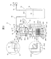
- FIG. 2 shows a part of the kneading mechanism 12 in a schematic schematic configuration diagram.
- the kneading mechanism 12 includes sand and additives (foaming agent) in the stirring tank 20 in a state where the stirring tank 20 is disposed at the kneading position (position of the stirring tank 20 shown in FIG. 2). , A water supply binder, water, etc.).
- the material supply unit 54 includes a sand supply unit 56, a binder supply unit 58, a foaming agent supply unit 60, and a water supply unit 62.
- the sand supply unit 56 includes a sand supply device 56A (blocked and illustrated) capable of storing sand and supplying sand, and a sand throwing chute 56B that receives the sand supplied by the sand supply device 56A.
- the sand supply device 56A includes an open / close gate (not shown) so that the amount of sand supplied can be adjusted.
- the sand throwing chute 56 ⁇ / b> B is inclined, and the lower end portion thereof is disposed inside the upper end opening portion of the stirring tank 20.
- dredged sand, alumina sand, olivine sand, chromite sand, zircon sand, mullite sand, and other artificial sand can be applied to the sand as the particulate aggregate.
- the binder supply unit 58 includes a binder supply device 58A (blocked and illustrated) that stores the water-soluble binder and supplies the water-soluble binder with a pump, and also includes a binder flow path 58B connected to the binder supply device 58A. Further, a valve device 58 ⁇ / b> C attached to the downstream end of the binder flow passage 58 ⁇ / b> B is installed in the lid 48 in the binder supply unit 58.
- the valve device 58C includes a valve (not shown) for opening and closing the downstream passage of the binder flow passage 58B, and an opening / closing mechanism (not shown) for opening and closing the valve.
- a supply port 58 ⁇ / b> D constituting the downstream end portion of the binder supply unit 58 is disposed on the upper side of the stirring tank 20 and is directed to the inside of the stirring tank 20.
- the foaming agent supply unit 60 includes a foaming agent supply device 60A (blocked and illustrated) that stores the liquid foaming agent and supplies the foaming agent with a pump, and is connected to the foaming agent supply device 60A.
- 60B is provided.
- a surfactant is added to the liquid foaming agent stored in the foaming agent supply device 60A.
- the foaming agent supply section 60 is provided with a valve device 60C attached to the downstream end of the foaming agent flow passage 60B.
- the valve device 60C includes a valve (not shown) for opening and closing the downstream passage of the foaming agent flow passage 60B, and an opening / closing mechanism (not shown) for opening and closing the valve.
- a supply port 60 ⁇ / b> D constituting the downstream end portion of the foaming agent supply unit 60 is disposed on the upper side of the stirring tank 20 and is directed to the inside of the stirring tank 20.
- the water supply unit 62 includes a water supply device 62A (blocked and illustrated) that stores water and supplies water with a pump, and includes a water flow passage 62B connected to the water supply device 62A.
- a valve device 62C attached to the downstream end of the water flow passage 62B is installed on the lid 48.
- the valve device 62C includes a valve (not shown) for opening and closing the downstream passage of the water passage 62B, and an opening / closing mechanism (not shown) for opening and closing the valve.
- a supply port 62 ⁇ / b> D constituting the downstream end of the water supply unit 62 is disposed on the upper side of the stirring tank 20 and is directed to the inside of the stirring tank 20.
- the stirring blade 24 is attached to the lower end portion of the rotating shaft 52, that is, the lower end portion of the blade-side rotating shaft 52C, and includes a rectangular frame-shaped frame body 24A, and is attached to the frame body 24A to the inside of the frame body 24A.
- a net 24B is provided.
- the frame 24A has a hollow cross section, and air circulates inside the hollow.
- the mesh portion 24B of the stirring blade 24 is provided in the entire region inside the frame of the frame body 24A, and is formed of a wire and has a lattice-like coarse mesh.
- the frame body 24A of the stirring blade 24 includes an upper frame portion 24A1 that constitutes an upper portion thereof and extends in the lateral direction, a lower frame portion 24A2 that is disposed in parallel with the upper frame portion 24A1, an upper frame portion 24A1, and a lower frame portion 24A1.
- a pair of side frame portions 24A3 arranged in parallel with each other by connecting the frame portions 24A2.
- the upper frame portion 24A1, the lower frame portion 24A2, and the side frame portion 24A3 have a rectangular cross-sectional shape that is orthogonal to each axis.
- a plurality (for example, a total of 20) of air supply ports 70 are formed in a portion 24I facing the inside of the frame 24A of the stirring blade 24.
- the air supply port 70 communicates with the hollow interior of the frame body 24A.
- the part 24I that faces the inner side of the frame refers to a part that faces in a direction parallel to the mesh part 24B arranged inside the frame of the frame body 24A, or a part whose angle with the parallel direction faces within 45 degrees.
- the air supply port 70 is set at a portion on both sides of the lower frame portion 24A2 and a lower portion of the side frame portion 24A3.
- the diameter of the air supply port 70 is set to 0.1 mm to 0.3 mm.
- air supply ports 70 constitute a part of the air supply mechanism 64.
- the air supply port 70 is formed in a direction perpendicular to the outer surface of the frame body 24A, but is not limited thereto. For example, it may be formed in a direction parallel to the mesh part 24B.
- the air supply mechanism 64 includes a compressor 66 (illustrated in a block form) shown at the right end in the drawing for supplying air, and is connected to the compressor 66 so as to circulate air from a connection portion with the compressor 66 to the air supply port 70.
- Air flow passage 68 is provided. Thereby, the air supply mechanism 64 can supply air from the air supply port 70 into the stirring tank 20.
- the pressure of the air supplied into the stirring tank 20 is set to 0.1 MPa to 0.5 MPa as an example.
- the air flow path 68 of the air supply mechanism 64 connects the first tube 74 that connects the compressor 66 and the water tank 76, the water tank 76, the water tank 76, and the frame body 24 ⁇ / b> A and passes through the inside of the rotary shaft 52.
- the two tubes 78 and the frame body 24A are formed.
- Water 90 is stored in the water tank 76, the downstream end of the first tube 74 is disposed in the water 90, and the upstream end of the second tube 78 is the top plate portion 76 ⁇ / b> A ( That is, it is disposed above the water 90).
- the air supplied into the agitation tank 20 is humidified (humidification by water aeration).
- the air flow path 68 of the air supply mechanism 64 is provided with a humidifying mechanism 72 including a water tank 76. Note that the humidity of the air supplied into the stirring tank 20 is 50% to 100% as an example in the present embodiment.
- the second tube 78 is attached to the joint portion 92 on the upper side of the drive side rotating shaft 52A.
- the joint portion 92 covers the upper end portion of the rotating shaft 52, that is, the upper end portion of the driving side rotating shaft 52A from the upper side, and, as shown in the enlarged partial view, the upper end portion of the driving side rotating shaft 52A (the rotating shaft 52). It is connected to the drive side rotating shaft 52A (rotating shaft 52) via a bearing 94 disposed on the outer peripheral side. Thereby, even if the rotating shaft 52 rotates, the joint part 92 does not rotate.
- the second tube 78 is arranged in a state of passing through the joint portion 92 through the lower hole portion and the side hole portion of the joint portion 92 and supported by the side portion of the joint portion 92.
- a valve device 96 is arranged in the air flow passage 68 (passage formed by the first tube 74 as an example in the present embodiment).
- the valve device 96 includes a valve (not shown) for opening and closing a predetermined part of the air flow passage 68 and an opening / closing mechanism (not shown) for opening and closing the valve.
- a pressure sensor 98 is disposed in the air flow passage 68 (passage formed by the second tube 78 as an example in the present embodiment). The pressure sensor 98 measures the pressure in a predetermined space in the air flow path 68.
- the agitation tank 20 is arranged at the kneading position (position shown in FIG. 2), and the filling port 22 of the bottom 20B of the agitation tank 20 is closed by the stop pin 26A of the filling port closing mechanism 26 (see FIG. 1). .
- Sand, a water-soluble binder, a foaming agent, and water are respectively supplied from the material supply unit 54 to the stirring tank 20 disposed in the kneading position (position shown in FIG. 2).
- air is supplied from the air supply port 70 into the stirring tank 20 by the air supply mechanism 64. Is done. Thereby, a foaming mixture is obtained.
- the upper mold 42 and the lower mold 44 are combined and arranged at a predetermined height position (not shown) by raising the lower mold 44 by the operation of the cylinder 14D. Further, it is heated to about 250 ° C.
- the stop pin 26A is pulled out from the filling port 22 of the bottom 20B. Further, the stirring blade 24 is retracted upward from the inside of the stirring tank 20 by the kneading blade moving mechanism 28 and the lid 48 is also retracted upward. Next, the stirring tank 20 and the mold pushing mechanism 18 are slid to the left in the figure by the horizontal movement mechanism 32, and the filling port 22 of the stirring tank 20 is directly above the filling port 46 of the upper wall portion 42A of the upper mold 42.
- the stirring tank 20 is arranged at a position (filling position).
- the stirring tank 20 and the mold extrusion mechanism 18 are slid to the right side in the drawing by the horizontal movement mechanism 32, the stirring tank 20 is returned to the kneading position, and the mold extrusion mechanism 18 is disposed immediately above the upper mold 42. Is done.
- a stop pin 26A is inserted into the filling port 22 of the bottom 20B, and sand, a water-soluble binder, a foaming agent, water, and water are supplied from the material supply unit 54. Are additionally supplied (supplemented).
- the air supply mechanism 64 causes the air supply mechanism 64 to agitate the sand and additives (foaming agent, water-soluble binder, water, etc.) in the stirring tank 20 from the air supply port 70. Air is supplied into the stirring tank 20. Thereby, air can be efficiently contained in the mixture a of sand and additive, and air can be uniformly dispersed by the rotation of the stirring blade 24. Therefore, in the case of this embodiment, compared with the case where air is not supplied from the stirring blade 24, the foaming mixture with favorable fluidity
- the stirring blade 24 includes the frame body 24A and the net portion 24B disposed inside the frame, so that during stirring, the stirring blade 24 passes through the inside of the frame body 24A.
- the mixture a can be finely divided by the mesh portion 24B so that air is included in the mixture a.
- the air supply port 70 is formed at a portion facing the inner side of the frame body 24A having a hollow cross section, air is blown into the mixture a that passes through the inner side of the frame body 24A. Air can be more efficiently contained in the mixture a.
- the air supply mechanism 64 humidifies the air by the humidification mechanism 72 and then supplies the air from the air supply port 70 into the stirring tank 20. For this reason, for example, even in an environment where the initial moisture ratio of the mixture a in the stirring tank 20 is suppressed and the mixture a being stirred is easily dried, the mixture a is not replenished. Therefore, foaming proceeds stably.
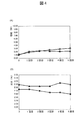
- FIG. 4 shows the results of kinematic viscosity measurement when humidified air is supplied from the air supply port into the stirring tank and when non-humidified air is supplied from the air supply port into the stirring tank.
- 4 (A)) and a graph comparing water measurement results (FIG. 4B) are shown.
- “kinematic viscosity” is a value related to kinematic viscosity, but means a value measured by a method described later.
- the horizontal axis indicates how many times the additional kneading is performed (details will be described later)
- the vertical axis in FIG. 4 (A) indicates kinematic viscosity measurement.
- FIG. 4B shows the result of moisture measurement.
- 0 on the horizontal axis indicates extraction after the initial kneading (described later).
- a white triangle mark indicates a case where air humidified to 100% humidity is supplied
- a white circle mark indicates a case where air which is not humidified is supplied.
- a black triangle indicates a case where air humidified to 100% humidity is supplied
- a black circle indicates a case where air which is not humidified is supplied.
- ESPAR # 90 (manufactured by Yamakawa Sangyo Co., Ltd.) is used as sand
- No. 3 water glass is used as a water-soluble binder
- Adeka Hope YES-25 (manufactured by ADEKA Co., Ltd.) is used as a foaming agent.
- the initial input amount of sand is 5 kg.
- the water-soluble binder is supplied at 0.65 wt% with respect to the sand
- the foaming agent is supplied at 0.03 wt% with respect to the sand
- the water is supplied at 3.20 wt% with respect to the sand.
- the air flow rate of air supplied from the air supply port is 8 L / min.
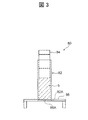
- FIG. 3 shows a measuring device 80 used for kinematic viscosity measurement.
- the measuring device 80 includes a cylindrical member 82 arranged so that the central axis is in the vertical direction, a columnar weight 84 that pushes the measurement target mixture b placed in the cylindrical member 82 from above, and a cylindrical member. And a base plate 86 that is horizontally disposed to support a lower end opening 82A of 82.
- the base plate 86 is formed with a small-diameter hole portion 86 ⁇ / b> A at a portion corresponding to the central portion of the lower end opening portion 82 ⁇ / b> A of the cylindrical member 82.
- the cylindrical member 82 has an outer diameter of 50 mm and an inner diameter of 42 mm.
- the weight 84 has a weight of 1,000 g and an outer diameter of 40 mm.
- the thickness of the base plate 86 is 6 mm, and the thickness of the portion through which the hole 86A penetrates, that is, the length of the hole 86A is 4 mm.
- the mixture b is put into the cylindrical member 82, and thereafter, a weight 84 is placed on the mixture b, and the mixture b is pushed from above by the weight 84. Then, it is measured how many seconds the mixture b passes between the two upper and lower points set in advance in the cylindrical member 82. Specifically, a line having a distance of 50 mm was inserted into the weight 84, and the time over which the line exceeded a certain height was measured to determine the time for the mixture b to pass through, that is, “kinematic viscosity”.
- the rotating shaft 52 having the stirring blade 24 attached to the lower end portion is disposed so as to be rotatable around its own axis, and rotates.
- the joint portion 92 that covers the upper end portion of the shaft 52 from above is connected to the rotating shaft 52 via a bearing 94 disposed on the outer peripheral side of the upper end portion of the rotating shaft 52. For this reason, even if the rotating shaft 52 rotates around its own axis, the joint portion 92 does not rotate.
- the second tube 78 for circulating the air supplied from the air supply port 70 into the stirring tank 20 passes through the inside of the rotating shaft 52, but the second tube 78 passes through the lower part and the side part of the joint part 92. Therefore, even if the second tube 78 rotates with the rotating shaft 52, the joint portion 92 supports the second tube 78 even if the second tube 78 rotates together with the rotating shaft 52. Is maintained. Thereby, it is possible to prevent the second tube 78 from being entangled when the rotation shaft 52 rotates.
- the second tube 78 prevents twisting by using a ring joint between a portion that is supported by the joint portion 92 and does not rotate and a portion that rotates through the inside of the rotating shaft 52. Note that other known twist prevention measures may be used.
- a pressure sensor 98 is disposed in the air flow path 68 of the air supply mechanism 64. For this reason, when the air supply port 70 is clogged, the detection value of the pressure sensor 98 is higher than when the air supply port 70 is not clogged. Can be detected automatically.
- the diameter of the air supply port 70 is set to 0.1 mm to 0.3 mm.
- the diameter of the air supply port 70 is set to 0.1 mm to 0.3 mm.
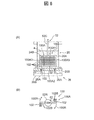
- FIG. 6A shows a front view of the main part of the modification
- FIG. 6B shows a schematic plan view of the frame.
- this modified example is different from the above-described embodiment in that a frame body 100A is provided instead of the frame body 24A (see FIG. 2) of the above-described embodiment.
- Other configurations are the same as those in the above embodiment.
- symbol is attached
- the stirring blade 100 as the stirring blade shown in FIG. 6 (A) and FIG. 6 (B) is the above embodiment except that the frame body 100A is provided instead of the frame body 24A (see FIG. 2) of the above embodiment.
- the configuration is the same as that of the stirring blade 24.
- the frame 100A is attached to the lower end of the rotating shaft 52 that rotates in a predetermined rotation direction (see the arrow 52R in FIG. 6B), that is, the lower end of the blade-side rotating shaft 52C, and has a hollow cross section and a rectangular frame shape. Is formed.
- the frame body 100A includes an upper frame portion 100A1, a lower frame portion 100A2, and a pair of side frame portions 100A3, similarly to the frame body 24A (see FIG.
- the upper frame portion 100A1, the lower frame portion 100A2, and the side frame portion 100A3 have a rectangular cross-sectional shape orthogonal to each axis.
- a mesh portion 24B is attached to the frame body 100A in the same manner as the frame body 24A (see FIG. 2) of the above embodiment.
- the frame 100A has a side on which the frame 100A rotates when the rotary shaft 52 rotates (see an arrow 100R in FIG. 6B).
- a plurality of air supply ports 102 are formed in a portion facing the opposite side.
- the air supply port 102 is formed so that air blows out on the opposite side to the rotation direction 52R of the rotation shaft 52 (see FIG. 6B).
- the direction of air blowing from the air supply port 102 is indicated by an arrow 102B.
- the air supply port 102 is set in a portion on both sides of the pair of side frame portions 100A3 and the lower frame portion 100A2 shown in FIG.
- the diameter of the air supply port 102 is set similarly to the diameter of the air supply port 70 (see FIG. 2) of the above embodiment.
- the “opposite side” when the air supply port 102 is formed at a portion facing the side opposite to the side on which the frame body 100 ⁇ / b> A rotates when the rotary shaft 52 rotates is a cross section perpendicular to the rotary shaft 52.
- the outer surface of the frame body 100A refers to a portion facing in a direction 180 degrees opposite to the direction in which the frame body 100A rotates and in a direction within 45 degrees from the opposite direction.
- the air supply port 102 is formed in a direction perpendicular to the outer surface of the frame body 100A, but is not limited thereto. For example, it may be formed in a direction parallel to the mesh part 24B.
- the air flow path 68 of the air supply mechanism 64 shown in FIG. 2 is provided with a humidifying mechanism 72 that humidifies the air supplied into the stirring tank 20.
- the air is supplied from the air supply port 70 into the stirring tank 20 after being humidified, for example, when the kneading mechanism operates in a humid environment or when the lid of the stirring tank is highly sealed, Alternatively, the air supply mechanism does not have to be equipped with a humidifying mechanism and is not humidified when water is replenished during stirring or when the initial moisture ratio of the mixture in the stirring tank is set high. May be fed into a stirred tank.
- the method of humidifying the air supplied into the stirring tank may be a method other than the above-described embodiment, such as heat evaporation, ultrasonic humidification, water spray, and the like.
- the stirring blades 24 and 100 as the stirring blades are provided with the frame bodies 24A and 100A and the mesh portion 24B.
- the stirring blades may be other types such as a propeller type stirring blade.
- the stirring blade may be used.
- the pressure sensor 98 is disposed in the air flow path 68, but a flow meter may be disposed instead of the pressure sensor.
- a flow meter By arranging the flow meter, the clogged state of the air supply port can be detected as in the pressure sensor.
- these structures are preferable, the structure which neither a pressure sensor nor a flow meter arrange
- the diameters of the air supply ports 70 and 102 are set to 0.1 mm to 0.3 mm, and such a configuration is preferable.
- the diameter of the air supply port is not necessarily limited to the above setting. It is not something. That is, the diameter and number of air supply ports can be set as appropriate depending on the particle diameter of the applied sand, the amount of sand particles, the type of binder, and the like.
- die 40 shown by FIG. 1 is a horizontal split metal mold
- die is made into a vertical split metal mold
- the mold may be a mold in which a mold making space is formed by the other mold and a filling port is formed through an upper wall portion disposed on the upper side of the mold.
Landscapes
- Engineering & Computer Science (AREA)
- Mechanical Engineering (AREA)
- Molds, Cores, And Manufacturing Methods Thereof (AREA)
- Mixers Of The Rotary Stirring Type (AREA)
- Casting Devices For Molds (AREA)
Abstract
流動性の良好な発泡混合物を得るまでの時間を短縮することができる混練機構、造型装置及び発泡混合物の製造方法を得る。撹拌槽(20)の中の粒子状骨材及び添加物を撹拌する撹拌翼(24)には、複数のエア供給口(70)が形成されている。エア供給機構(64)は、エア流通路(68)に加湿機構(72)を備え、加湿機構(72)によって加湿されたエアをエア供給口(70)から撹拌槽(20)の中に供給する。また、エア供給口(70)は、撹拌翼(24)の枠体(24A)の枠内側に臨む部位に形成されている。
Description
本発明は、混練機構、造型装置及び発泡混合物の製造方法に関する。
撹拌槽に粒子状骨材、水溶性バインダ及び水を入れて撹拌することで発泡混合物を得る方法がある(例えば、特許文献1参照)。
しかしながら、そのような技術では、流動性の良好な発泡混合物を得るまでに比較的時間を要する。なお、撹拌槽の充填ノズルに挿入した押込み棒からエアを吹出すことで砂の撹拌を促進しようとする技術があるが(例えば、特許文献2参照)、この技術ではエア吹出口の位置や数が充填ノズルの位置や数によって制限されるうえ、充填ノズルの近傍の砂の撹拌に寄与するものに過ぎない。
本発明は、上記事実を考慮して、流動性の良好な発泡混合物を得るまでの時間を短縮することができる混練機構、造型装置及び発泡混合物の製造方法を得ることが目的である。
本発明の第1の態様の混練機構は、粒子状骨材及び添加物を貯留する撹拌槽と、前記撹拌槽の中の粒子状骨材及び発泡剤を含む添加物を撹拌する撹拌羽根と、前記撹拌羽根にエア供給口が形成され、前記エア供給口から前記撹拌槽の中にエアの供給が可能なエア供給機構と、を有する。
上記構成によれば、撹拌槽の中に貯留された粒子状骨材及び添加物が撹拌羽根によって撹拌される。ここで、撹拌羽根にはエア供給口が形成されており、エア供給機構はエア供給口から撹拌槽の中にエアの供給が可能となっている。そして、粒子状骨材及び発泡剤を含む添加物が撹拌羽根によって撹拌されながら、エア供給口から撹拌槽の中にエアが供給されると、粒子状骨材及び添加物の中に効率的にエアを含ませることができる。よって、撹拌羽根からエアが供給されない場合と比べて、短時間の撹拌で流動性の良好な発泡混合物を得ることができる。
本発明の第2の態様の混練機構は、第1の態様の構成において、前記撹拌羽根は、断面中空形状の枠体であって該中空部分を前記エアが流通する枠体と、前記枠体に取り付けられて前記枠体の枠内側に配置された網部と、を備えると共に、前記枠体の枠内側に臨む部位に前記エア供給口が形成されている。
上記構成によれば、撹拌羽根は枠体であって該中空部分を前記エアが流通する枠体とその枠内側に配置された網部とを備えているので、撹拌時には、枠体の枠内側を通過させる粒子状骨材と添加物との混合物を網部によって細かく分断させて混合物の中にエアを含ませることができる。ここで、断面中空形状の枠体の枠内側に臨む部位にはエア供給口が形成されているため、枠体の枠内側を通過させる混合物にエアが吹き込まれるので、撹拌中の混合物の中に一層効率的にエアを含ませることができる。
本発明の第3の態様混練機構は、第1の態様の構成において、前記撹拌羽根は、断面中空形状の枠体であって該中空部分を前記エアが流通する枠体と、前記枠体に取り付けられて前記枠体の枠内側に配置された網部と、を備えると共に、前記枠体には前記回転軸の回転時に前記枠体が回転移動する側とは反対側に向く部位に前記エア供給口が形成されている。
上記構成によれば、撹拌羽根は枠体であって該中空部分を前記エアが流通する枠体とその枠内側に配置された網部とを備えているので、撹拌時には、枠体の枠内側を通過させる粒子状骨材と添加物との混合物を網部によって細かく分断させて混合物の中にエアを含ませることができる。ここで、断面中空形状の枠体は、所定の回転方向に回転する回転軸に取り付けられており、枠体には回転軸の回転時に枠体が回転移動する側とは反対側に向く部位にエア供給口が形成されている。このため、撹拌羽根による撹拌時には、枠体が回転移動する側とは反対側の領域に乱流が生じると共にそのような乱流が生じている領域にエアが吹き込まれるので、混合物の中に一層効率的にエアを含ませることができる。
本発明の第4の態様の混練機構は、第1の態様~第3の態様のいずれか1つの構成において、前記エア供給機構のエア流通路には、前記撹拌槽の中に供給するエアを加湿する加湿機構が設けられている。
上記構成によれば、エア供給機構のエア流通路に設けられた加湿機構が、撹拌槽の中に供給するエアを加湿する。そして、粒子状骨材及び添加物が撹拌羽根によって撹拌されながら、エア供給口から撹拌槽の中に加湿されたエアが供給されると、粒子状骨材及び添加物の混合物にはエアに加えて水分が供給されることになる。このため、例えば、撹拌槽の中の混合物の当初の水分比率が抑えられていてかつ撹拌中の混合物が乾燥し易い環境下にあっても、別途水分を補給することなく、混合物の乾燥を抑えることができ、発泡が安定的に進行する。
本発明の第5の態様の混練機構は、第1の態様~第3の態様のいずれか1つの構成において、軸線が鉛直方向に沿って設定されると共に下端部に前記撹拌羽根が取り付けられ、自身の軸線周りに回転可能に配置された回転軸と、前記回転軸の内部を通り、前記エア供給口から前記撹拌槽の中に供給するエアを流通させるチューブと、前記回転軸の上端部を上方側から覆うと共に、前記回転軸の上端部の外周側に配置された軸受を介して前記回転軸に連結されたジョイント部と、を有し、前記チューブが前記ジョイント部の下部及び側部を通って前記ジョイント部を貫通した状態で配置されて前記ジョイント部の側部に支持されている。
上記構成によれば、撹拌羽根が下端部に取り付けられた回転軸は、自身の軸線周りに回転可能に配置されており、回転軸の上端部を上方側から覆うジョイント部は、回転軸の上端部の外周側に配置された軸受を介して回転軸に連結されている。このため、回転軸が自身の軸線周りに回転しても、ジョイント部は回転しない。また、エア供給口から撹拌槽の中に供給するエアを流通させるチューブは回転軸の内部を通っているが、当該チューブはジョイント部の下部及び側部を通ってジョイント部を貫通した状態で配置されてジョイント部の側部に支持されているので、チューブが回転軸と共に回転してもジョイント部がチューブを支持する位置は維持される。これにより、回転軸の回転時にチューブが絡まるのを防止することができる。
本発明の第6の態様の混練機構は、第1の態様~第3の態様のいずれか1つの構成において、前記エア供給機構のエア流通路に圧力センサが配置されている。
上記構成によれば、エア供給口が目詰まりしている場合にはエア供給口が目詰まりしていない場合よりも圧力センサの検出値が高くなるので、エア供給口の目詰まり状態を間接的に検出することができる。
本発明の第7の態様の混練機構は、第1の態様~第3の態様のいずれか1つの構成において、前記エア供給口の直径が0.1mm~0.3mmに設定されている。
上記構成によれば、エア供給口の直径を0.1mm以上にすることで圧力損失が抑えられてエアの良好な吹き出しが可能となっており、また、エア供給口の直径を0.3mm以下にすることで撹拌後に撹拌羽根を撹拌槽の中から上方側に移動させる際に粒子状骨材がエア供給口からエア流通路に入り込むのを防止又は抑制することができる。
本発明の第8の態様の造型装置は、一方の型と他方の型とで鋳型造型用空間を形成すると共に、上側に配置される上壁部に被充填口が貫通形成された金型と、前記撹拌槽の底部に充填口が貫通形成され、前記撹拌槽が、前記撹拌槽の中の粒子状骨材及び添加物を前記撹拌羽根によって撹拌可能な第一位置と、前記充填口が前記被充填口の直上となる第二位置と、の間で移動可能に配置された、第1の態様~第3の態様のいずれか1つの混練機構と、前記第一位置に配置された状態の前記撹拌槽の前記充填口を閉塞する充填口閉塞機構と、前記第一位置に配置された状態の前記撹拌槽に粒子状骨材及び発泡剤を含む添加物を供給する材料供給部と、前記第二位置に配置された状態の前記撹拌槽の内容物を上方側から押圧する押圧機構と、を有する。
上記構成によれば、第一位置に撹拌槽が配置された状態では、撹拌槽の底部の充填口が充填口閉塞機構によって閉塞され、材料供給部から撹拌槽に粒子状骨材及び添加物が供給される。そして、撹拌槽の中の粒子状骨材及び発泡剤を含む添加物が撹拌羽根によって撹拌されながら、エア供給口から撹拌槽の中にエアが供給されると、粒子状骨材及び添加物の中に効率的にエアを含ませることができ、短時間の撹拌で流動性の良好な発泡混合物を得ることができる。一方、撹拌槽の充填口が金型の上壁部の被充填口の直上となる第二位置に撹拌槽が配置された状態では、撹拌槽の内容物である発泡混合物が押圧機構によって上方側から押圧される。これにより、発泡混合物は、充填口及び被充填口を通った後、一方の型と他方の型とで形成された鋳型造型用空間に充填され、固化することで鋳型に造型される。
本発明の第9の態様の発泡混合物の製造方法は、撹拌槽と、前記撹拌槽の内容物を撹拌する撹拌羽根と、前記撹拌羽根にエア供給口が形成されて前記エア供給口から前記撹拌槽の中にエアの供給が可能なエア供給機構と、を用いた、発泡混合物の製造方法であって、前記撹拌槽の中で粒子状骨材及び発泡剤を含む添加物を前記撹拌羽根によって撹拌しながら前記エア供給機構によって前記エア供給口から前記撹拌槽の中にエアを供給する。
上記構成によれば、撹拌槽の中で粒子状骨材及び発泡剤を含む添加物を撹拌羽根によって撹拌しながら、撹拌羽根に形成されたエア供給口からエア供給機構によって撹拌槽の中にエアを供給する。これにより、粒子状骨材及び添加物の混合物の中に効率的にエアを含ませることができるので、撹拌羽根からエアが供給されない場合と比べて、短時間の撹拌で流動性の良好な発泡混合物を得ることができる。
本発明の第10の態様の発泡混合物の製造方法は、第1の態様の構成において、前記エア供給機構は、エアを加湿してから当該エアを前記エア供給口から前記撹拌槽の中に供給する。
上記構成によれば、エア供給口から撹拌槽の中に加湿されたエアが供給される。このため、例えば、撹拌槽の中の混合物の当初の水分比率が抑えられていてかつ撹拌中の混合物が乾燥し易い環境下にあっても、別途水分を補給することなく、混合物の乾燥を抑えることができるので、発泡が安定的に進行する。
以上説明したように、本発明によれば、粒子状骨材及び添加物の中に効率的にエアを含ませることができ、流動性の良好な発泡混合物を得るまでの時間を短縮することができるという優れた効果を有する。
この出願は、日本国で2016年4月8日に出願された特願2016-078318号に基づいており、その内容は本出願の内容として、その一部を形成する。
また、本発明は以下の詳細な説明により更に完全に理解できるであろう。しかしながら、詳細な説明および特定の実施例は、本発明の望ましい実施の形態であり、説明の目的のためにのみ記載されているものである。この詳細な説明から、種々の変更、改変が、当業者にとって明らかだからである。
出願人は、記載された実施の形態のいずれをも公衆に献上する意図はなく、開示された改変、代替案のうち、特許請求の範囲内に文言上含まれないかもしれないものも、均等論下での発明の一部とする。
本明細書あるいは請求の範囲の記載において、名詞及び同様な指示語の使用は、特に指示されない限り、または文脈によって明瞭に否定されない限り、単数および複数の両方を含むものと解釈すべきである。本明細書中で提供されたいずれの例示または例示的な用語(例えば、「等」)の使用も、単に本発明を説明し易くするという意図であるに過ぎず、特に請求の範囲に記載しない限り本発明の範囲に制限を加えるものではない。
また、本発明は以下の詳細な説明により更に完全に理解できるであろう。しかしながら、詳細な説明および特定の実施例は、本発明の望ましい実施の形態であり、説明の目的のためにのみ記載されているものである。この詳細な説明から、種々の変更、改変が、当業者にとって明らかだからである。
出願人は、記載された実施の形態のいずれをも公衆に献上する意図はなく、開示された改変、代替案のうち、特許請求の範囲内に文言上含まれないかもしれないものも、均等論下での発明の一部とする。
本明細書あるいは請求の範囲の記載において、名詞及び同様な指示語の使用は、特に指示されない限り、または文脈によって明瞭に否定されない限り、単数および複数の両方を含むものと解釈すべきである。本明細書中で提供されたいずれの例示または例示的な用語(例えば、「等」)の使用も、単に本発明を説明し易くするという意図であるに過ぎず、特に請求の範囲に記載しない限り本発明の範囲に制限を加えるものではない。
本発明の一実施形態に係る混練機構を備えた造型装置及び発泡混合物の製造方法について図1~図5を用いて説明する。図1には、本実施形態に係る造型装置10が概略正面図で示されている。なお、上下左右に関しては、特に指示されたり文脈上明らかである場合を除いて、図中での上下左右を意味する。
(造型装置の全体構成)
まず、図1に示される造型装置10の全体構成について概説する。
まず、図1に示される造型装置10の全体構成について概説する。
造型装置10は、装置右側に混練機構12を有する。混練機構12は、粒子状骨材としての砂及び添加物を貯留する撹拌槽20(「混練槽」ともいう。)を備えると共に、撹拌槽20の中の内容物(砂及び添加物)を撹拌する撹拌羽根としての撹拌翼24(「混練翼」ともいう。)を備える。容器状とされた撹拌槽20の底部20Bには複数の充填口22が貫通形成されており、図中において撹拌槽20の下方側には充填口22を閉塞可能な充填口閉塞機構26が設けられている。また、混練機構12は、撹拌翼24を、撹拌槽20の内部に位置させる使用位置(図1に示される位置)と、撹拌槽20の内部から上方側へ退避させる退避位置(図示省略)と、の間で(矢印Y方向に)移動させる混練翼移動機構28を備える。なお混練機構12は、添加物として少なくとも発泡剤を含み、発泡性砂型の素材を混練する。典型的には、水溶性バインダおよび水をも含むが、これには限定されず、また、他の添加物を含んでもよい。
また、造型装置10は、混練機構12の撹拌槽20を左右方向に延びるフレーム部30に沿って(矢印X方向に)移動させるための水平移動機構32を備える。水平移動機構32は、撹拌翼24が退避位置に配置された状態で、撹拌槽20を、撹拌翼24の下方側となる第一位置としての混練用位置(図1に示される位置と同じ位置)と、前記混練用位置よりも装置左側の第二位置としての充填用位置(図示省略)と、の間で移動させるための機構とされている。前記混練用位置は、撹拌槽20の中の砂及び添加物を撹拌翼24によって撹拌可能な位置に設定され、前記充填用位置は、いずれも後述する金型40と押圧機構16との間の位置に設定されている。
また、造型装置10は、混練機構12よりも装置左側でかつ装置下部側に金型機構14を有する。金型機構14は、混練機構12で混練された発泡混合物を所定の形状に成形するための金型40を備える。また、金型機構14の直上側で装置上部には、押圧機構16(充填機構)が設けられている。押圧機構16は、撹拌槽20が前記充填用位置(図示省略)に配置された状態での当該撹拌槽20の内容物である発泡混合物を上方側から押圧して撹拌槽20の充填口22から金型40に発泡混合物を充填(射出)させるように構成されている。さらに、金型機構14よりも装置上方側かつ押圧機構16よりも装置下方側には、撹拌槽20の装置左側に鋳型押出機構18(上金型鋳型押出機構)が設けられている。鋳型押出機構18は、金型機構14と連動して金型40を開くことで金型40から鋳型を取り出すための機構とされる。また、鋳型押出機構18は、本実施形態では撹拌槽20に連結部19を介して装置左右方向に連結されており、撹拌槽20と共に装置左右方向に移動可能とされている。
(各機構の概説)
次に、各機構について概説する。
次に、各機構について概説する。
金型機構14では、金型40が一方の型としての上型42と他方の型としての下型44とで鋳型造型用空間を形成する。すなわち、本実施形態における金型40は、水平割の金型とされている。下型44は、昇降フレーム14Aの上面に取り付けられている。昇降フレーム14Aは、機台14Bの四隅部において装置上下方向に立設されたガイドロッド14Cに沿って昇降可能とされると共に、昇降フレーム14Aの下方側において上向きに設置されたシリンダ14Dのピストンロッド14D1に支持されている。すなわち、昇降フレーム14Aは、シリンダ14Dのピストンロッド14D1の伸縮に応じて昇降するようになっている。これに対して、上型42は、下型44の直上に配置され、ガイドロッド14Cに装着された支持機構部14Eに支持されている。また、上型42の上壁部42A(金型40において上側に配置される上壁部)には被充填口46が貫通形成されている。
金型機構14の直上側で装置上部に設けられた押圧機構16は、フレーム部30の天井部30Aに設けられ、ピストン16Aを備える。このピストン16Aには複数の排気孔(図示省略)が貫通形成されている。また、ピストン16Aは、下向きのシリンダ16Bのピストンロッド16B1の下端部側に接続されており、シリンダ16Bの作動により上下動するようになっている。
押圧機構16よりも装置下方側で撹拌槽20の装置左側に設けられた鋳型押出機構18は、鋳型押出用部材18Aを備える。鋳型押出用部材18Aには、複数の鋳型押出ピンが形成され、これらの鋳型押出ピンは、上型42に形成された被充填口46に挿入可能とされている。鋳型押出用部材18Aは、下向きのシリンダ18Bのピストンロッド18B1の下端部側に接続されており、シリンダ18Bの作動により上下動するようになっている。
撹拌槽20及び鋳型押出機構18を装置左右方向に移動させるための水平移動機構32は、フレーム部30に装置左右方向に延びるガイド部32Aを備えると共に、ガイド部32Aに沿って走行可能な走行台車(図示省略)を備えている。すなわち、水平移動機構32は、前記走行台車がガイド部32Aに沿って走行(移動)することで、撹拌槽20及び鋳型押出機構18を移動させるようになっている。なお、フレーム部30は、前述したガイドロッド14Cの上端部に固定されている。また、撹拌槽20の前記充填用位置(図示省略)は、撹拌槽20の充填口22が上型42の被充填口46の直上となる位置とされている。また、図中では、鋳型押出機構18が金型40の直上から装置左側に退避した位置に配置された状態を二点鎖線で示している。
混練機構12は、前述したように撹拌槽20を備えている。撹拌槽20は、上下方向を中心軸線方向とする筒状部20Aと、筒状部20Aの下端に固着されて筒状部20Aの下端側開口部を塞ぐ底部20Bと、を備えている。本実施形態では、撹拌槽20の容積は、金型40の鋳型造型用空間の容積よりもかなり大きく設定されている。また、筒状部20Aの上端側開口部には蓋48が配置可能とされている。
また、混練機構12は、撹拌翼24を作動させるための混練翼作動機構50をフレーム部30の天井部30A側に備える。混練翼作動機構50は、撹拌翼24を回転させるための回転軸52を備え、その回転軸52が自身の軸線周りに回転可能に配置されかつ駆動力伝達部50Bを介してモータ50Mの出力軸に接続された構成となっている。すなわち、混練機構12は、撹拌槽20が混練用位置(図1に示される撹拌槽20の位置と同じ位置)に配置された状態でモータ50Mが作動することで当該撹拌槽20の内容物を撹拌翼24が混練するようになっている。なお、回転軸52は、その軸線が鉛直方向に沿って設定されている。この回転軸52は、撹拌翼24に接続された翼側回転軸52Cと、駆動力伝達部50Bにより伝達された駆動力を受ける駆動側回転軸52Aと、翼側回転軸52Cと駆動側回転軸52Aとを連結する連結部52Bと、で構成されている。
また、混練翼移動機構28は、下向きのシリンダ28Aと、シリンダ28Aの作動に応じて昇降する昇降台部28Bと、を備えている。昇降台部28Bは、軸受部28Cを介して駆動側回転軸52Aを回転可能に支持すると共に、他部材を介して蓋48及びモータ50Mを支持している。これにより、シリンダ28Aの作動に応じて撹拌翼24、蓋48及びモータ50Mが昇降する構成となっている。
また、混練翼作動機構50の下方側に設けられた充填口閉塞機構26は、撹拌槽20の底部20Bの充填口22の閉塞用として止めピン26A(栓)を充填口22の数と同数備えている。止めピン26Aは、水平配置されたベースプレート26Bから上方側に突出している。また、ベースプレート26Bは、上向きのシリンダ26Cのピストンロッド26C1の上端部に取り付けられており、シリンダ26Cの作動により上下動するようになっている。そして、充填口閉塞機構26は、撹拌槽20が混練用位置(図1に示される撹拌槽20の位置と同じ位置)に配置された状態での当該撹拌槽20の充填口22を止めピン26Aで閉塞することが可能とされている。なお、充填口閉塞機構26のシリンダ26Cは、部材を介してフレーム部30に支持されている。
(混練機構の詳細説明)
次に、図2を参照しながら混練機構12について更に説明する。図2には、混練機構12の一部が模式的な概略構成図で示されている。
次に、図2を参照しながら混練機構12について更に説明する。図2には、混練機構12の一部が模式的な概略構成図で示されている。
図2に示されるように、混練機構12は、撹拌槽20が混練用位置(図2に示される撹拌槽20の位置)に配置された状態において当該撹拌槽20に砂及び添加物(発泡剤、水溶性バインダ、水等)を供給する材料供給部54を備える。材料供給部54は、砂供給部56、バインダ供給部58、発泡剤供給部60、及び水供給部62を備える。
砂供給部56は、砂を貯留すると共に砂を供給可能な砂供給装置56A(ブロック化して図示)を備えると共に、砂供給装置56Aにより供給された砂を受ける砂投入シュート56Bを備える。砂供給装置56Aは、図示しない開閉ゲートを備え、砂の供給量を調整できるようになっている。また、砂投入シュート56Bは、傾斜状とされ、その下端部が撹拌槽20の上端開口部の内側に配置されている。
なお、粒子状骨材としての砂には、例えば、硅砂、アルミナ砂、オリビン砂、クロマイト砂、ジルコン砂、ムライト砂等の他、各種の人工砂(いわゆる人工骨材)を適用することができる。
バインダ供給部58は、水溶性バインダを貯留すると共にポンプで水溶性バインダを供給するバインダ供給装置58A(ブロック化して図示)を備えると共に、バインダ供給装置58Aに接続されたバインダ流通路58Bを備える。また、バインダ供給部58には、バインダ流通路58Bの下流側端部に取り付けられた弁装置58Cが蓋48に設置されている。弁装置58Cは、バインダ流通路58Bの下流側通路の開閉用とされた弁(図示省略)を備えると共に、前記弁を開閉させる開閉機構(図示省略)を備える。バインダ供給部58の下流側端部を構成する供給口58Dは、撹拌槽20の上方側に配置されて撹拌槽20の内側へ向けられている。
発泡剤供給部60は、液状の発泡剤を貯留すると共にポンプで発泡剤を供給する発泡剤供給装置60A(ブロック化して図示)を備えると共に、発泡剤供給装置60Aに接続された発泡剤流通路60Bを備える。なお、本実施形態では、発泡剤供給装置60Aに貯留される液状の発泡剤には界面活性剤が添加されている。また、発泡剤供給部60には、発泡剤流通路60Bの下流側端部に取り付けられた弁装置60Cが設けられている。弁装置60Cは、発泡剤流通路60Bの下流側通路の開閉用とされた弁(図示省略)を備えると共に、前記弁を開閉させる開閉機構(図示省略)を備える。発泡剤供給部60の下流側端部を構成する供給口60Dは、撹拌槽20の上方側に配置されて撹拌槽20の内側へ向けられている。
水供給部62は、水を貯留すると共にポンプで水を供給する水供給装置62A(ブロック化して図示)を備えると共に、水供給装置62Aに接続された水流通路62Bを備える。また、水供給部62には、水流通路62Bの下流側端部に取り付けられた弁装置62Cが蓋48に設置されている。弁装置62Cは、水流通路62Bの下流側通路の開閉用とされた弁(図示省略)を備えると共に、前記弁を開閉させる開閉機構(図示省略)を備える。水供給部62の下流側端部を構成する供給口62Dは、撹拌槽20の上方側に配置されて撹拌槽20の内側へ向けられている。
一方、撹拌翼24は、回転軸52の下端部すなわち翼側回転軸52Cの下端部に取り付けられて矩形枠状の枠体24Aを備えると共に、枠体24Aに取り付けられて枠体24Aの枠内側に配置された網部24Bを備えている。枠体24Aは、その断面が中空で、中空の内部をエアが流通する。撹拌翼24の網部24Bは、枠体24Aの枠内側の全域に設けられ、ワイヤで構成されて格子状の粗い網目を有している。また、撹拌翼24の枠体24Aは、その上部を構成して横方向に延びる上枠部24A1と、この上枠部24A1と平行に配置された下枠部24A2と、上枠部24A1及び下枠部24A2を繋いで互いに平行に配置される一対の側枠部24A3と、を備えている。上枠部24A1、下枠部24A2及び側枠部24A3は、各々の軸線に直交する断面形状が矩形状とされている。
撹拌翼24の枠体24Aの枠内側に臨む部位24Iには、部分拡大図に示されるように、複数(一例として計20個)のエア供給口70が形成されている。エア供給口70は、枠体24Aの中空の内部と連通する。枠内側に臨む部位24Iは、枠体24Aの枠内側に配置された網部24Bと平行な方向を向く部位、または、平行な方向との角度が45度以内を向く部位をいう。エア供給口70は、本実施形態では一例として、下枠部24A2の両サイド側の部位及び側枠部24A3の下部に設定されている。また、エア供給口70の直径は、0.1mm~0.3mmに設定されている。これらのエア供給口70は、エア供給機構64の一部を構成している。エア供給口70は、枠体24Aの外面に垂直方向に形成されるが、これには限定されない。例えば、網部24Bと平行な方向を向いて形成されてもよい。
エア供給機構64は、エアを供給する図中右端に示されるコンプレッサ66(ブロック化して図示)を備えると共に、コンプレッサ66に接続されてコンプレッサ66との接続部からエア供給口70までエアを流通させるためのエア流通路68を備える。これにより、エア供給機構64は、エア供給口70から撹拌槽20の中にエアの供給が可能とされている。なお、撹拌槽20の中に供給するエアの圧力は、本実施形態では一例として0.1MPa~0.5MPaとされている。エア供給機構64のエア流通路68は、コンプレッサ66と水タンク76とを繋ぐ第一チューブ74と、水タンク76と、水タンク76と枠体24Aとを繋ぐと共に回転軸52の内部を通る第二チューブ78と、枠体24Aと、で形成されている。
水タンク76には水90が貯留されており、第一チューブ74の下流側端部は水90の中に配置され、第二チューブ78の上流側端部は水タンク76の天板部76A(すなわち水90よりも上方側)に配置されている。このような第一チューブ74、水タンク76及び第二チューブ78の配置構成により、撹拌槽20の中に供給するエアを加湿するようになっている(水散気による加湿)。すなわち、エア供給機構64のエア流通路68には、水タンク76を含んで構成された加湿機構72が設けられている。なお、撹拌槽20の中に供給するエアの湿度は、本実施形態では一例として50%~100%とされている。
また、第二チューブ78は、駆動側回転軸52Aの上方側でジョイント部92に装着されている。ジョイント部92は、回転軸52の上端部すなわち駆動側回転軸52Aの上端部を上方側から覆うと共に、部分拡大図に示されるように、駆動側回転軸52A(回転軸52)の上端部の外周側に配置された軸受94を介して駆動側回転軸52A(回転軸52)に連結されている。これにより、回転軸52が回転してもジョイント部92は回転しない構造になっている。そして、第二チューブ78がジョイント部92の下部の孔部及び側部の孔部を通ってジョイント部92を貫通した状態で配置されてジョイント部92の側部に支持されている。
また、エア流通路68(本実施形態では一例として第一チューブ74で形成される通路)には、弁装置96が配置されている。弁装置96は、エア流通路68の所定部位の開閉用とされた弁(図示省略)を備えると共に、前記弁を開閉させる開閉機構(図示省略)を備える。また、エア流通路68(本実施形態では一例として第二チューブ78で形成される通路)には、圧力センサ98が配置されている。圧力センサ98は、エア流通路68における所定空間の圧力を測定する。
(鋳型の造型)
次に、本実施形態の造型装置10(図1参照)による砂鋳型(砂中子)の造型について概説する。
次に、本実施形態の造型装置10(図1参照)による砂鋳型(砂中子)の造型について概説する。
まず、撹拌槽20が混練用位置(図2に示される位置)に配置され、撹拌槽20の底部20Bの充填口22が充填口閉塞機構26(図1参照)の止めピン26Aによって閉塞される。この混練用位置(図2に示される位置)に配置された状態の撹拌槽20には、材料供給部54から砂、水溶性バインダ、発泡剤及び水がそれぞれ供給される。そして、撹拌槽20の中の混合物a(砂、水溶性バインダ、発泡剤及び水)が撹拌翼24によって撹拌されながら、エア供給機構64によってエア供給口70から撹拌槽20の中にエアが供給される。これにより、発泡混合物が得られる。
一方、図1に示される金型40は、シリンダ14Dの作動により下型44を上昇させることで、上型42及び下型44が合わせられてかつ所定の高さ位置に配置され(図示省略)、更に250℃程度に加熱される。
これに対して、撹拌槽20は、その底部20Bの充填口22から止めピン26Aが抜かれる。また、混練翼移動機構28によって撹拌翼24が撹拌槽20の内部から上方側へ退避させられると共に蓋48も上方側へ退避させられる。次に、撹拌槽20及び鋳型押出機構18が水平移動機構32によって図中左側にスライド移動させられ、撹拌槽20の充填口22が上型42の上壁部42Aの被充填口46の真上となる位置(充填用位置)に撹拌槽20が配置させられる。
この状態で撹拌槽20の内容物である発泡混合物が押圧機構16のピストン16Aによって上方側から押圧されると、発泡混合物は、撹拌槽20の充填口22及び上型42の被充填口46を通った後、上型42と下型44とで形成された鋳型造型用空間に充填(押圧射出)される。そして、加熱された金型40の熱により発泡混合物が乾燥して固化し、鋳型が造型される。
次に、撹拌槽20及び鋳型押出機構18が水平移動機構32によって図中右側にスライド移動させられ、撹拌槽20が混練用位置に戻されると共に、鋳型押出機構18が上型42の直上に配置される。混練用位置に戻された撹拌槽20には、図2に示されるように底部20Bの充填口22に止めピン26Aが挿入され、材料供給部54から砂、水溶性バインダ、発泡剤及び水及がそれぞれ追加供給(補充)される。そして、撹拌槽20の中の混合物aが撹拌翼24によって撹拌されながらエア供給機構64によってエア供給口70から撹拌槽20の中にエアが供給されて次回の鋳型造型用の発泡混合物が製造される。一方、図1に示される上型42の被充填口46には、鋳型押出機構18の鋳型押出用部材18Aの鋳型押出ピンが挿入されると共に下型44が下降する等して造型された鋳型が取り出される。
(発泡混合物の製造方法及び混練機構の作用・効果)
次に、図2を参照しながら発泡混合物の製造方法について説明すると共に、混練機構12の作用及び効果について説明する。
次に、図2を参照しながら発泡混合物の製造方法について説明すると共に、混練機構12の作用及び効果について説明する。
本実施形態の発泡混合物の製造方法では、撹拌槽20の中で砂及び添加物(発泡剤、水溶性バインダ、水等)を撹拌翼24によって撹拌しながらエア供給機構64によってエア供給口70から撹拌槽20の中にエアを供給する。これにより、砂及び添加物の混合物aの中に効率的にエアを含ませることができると共に、撹拌翼24の回転によってエアを均一的に分散させることができる。したがって、本実施形態の場合には、撹拌翼24からエアが供給されない場合と比べて、短時間の撹拌で流動性の良好な発泡混合物を得ることができる。
また、本実施形態の混練機構12では、撹拌翼24は、枠体24Aと、その枠内側に配置された網部24Bと、を備えているので、撹拌時には、枠体24Aの枠内側を通過させる砂、水溶性バインダ、発泡剤及び水の混合物aを網部24Bによって細かく分断させて混合物aの中にエアを含ませることができる。ここで、断面中空形状の枠体24Aの枠内側に臨む部位にはエア供給口70が形成されているため、枠体24Aの枠内側を通過させる混合物aにエアが吹き込まれるので、撹拌中の混合物aの中に一層効率的にエアを含ませることができる。
また、本実施形態では、エア供給機構64は、加湿機構72でエアを加湿してから当該エアをエア供給口70から撹拌槽20の中に供給する。このため、例えば、撹拌槽20の中の混合物aの当初の水分比率が抑えられていてかつ撹拌中の混合物aが乾燥し易い環境下にあっても、別途水分を補給することなく、混合物aの乾燥を抑えることができるので、発泡が安定的に進行する。
図4には、エア供給口から撹拌槽の中に加湿したエアが供給された場合と、エア供給口から撹拌槽の中に加湿しないエアが供給された場合とで、動粘測定結果(図4(A))及び水分測定結果(図4(B))を比較したグラフが示されている。ここで、「動粘」とは、動粘度に関連する値であるが、後述の方法で測定した値をいう。なお、図4(A)及び図4(B)では、横軸は何回目の追加混練後の抜き取りであるか(詳細後述)を示しており、図4(A)の縦軸は動粘測定した結果を示し、図4(B)の縦軸は水分測定した結果を示している。なお、横軸の0は初期混練後の抜き取りを示している(後述)。図4(A)のグラフにおいて、白抜き三角印は湿度100%に加湿したエアが供給された場合を示し、白抜き丸印は加湿しないエアが供給された場合を示す。また、図4(B)のグラフにおいて、黒塗りの三角印は湿度100%に加湿したエアが供給された場合を示し、黒塗りの丸印は加湿しないエアが供給された場合を示す。
図4に測定結果が示された実験の方法について説明する。まず、図5を参照しながら実験のフローについて説明する。この実験では、最初に、材料(砂、水溶性バインダ、発泡剤及び水)を約5kg(詳細後述)投入し(S1)、初期の混練(撹拌)を420秒行う(S2)。次に、砂等で構成される混合物を3.1kg分抜き取り(S3)、抜き取った混合物についての動粘測定及び水分測定を行う(S4)。なお、動粘測定については後述する。次に、砂等で構成される混合物(すなわち、砂、水溶性バインダ、発泡剤及び水)を3.1kg分補充し(S5)、追加の混練(撹拌)を45秒行う(S6)。その後はS3に戻り、S3~S6を5回繰り返す。
本実験では、砂としてはエスパール#90(山川産業株式会社製)、水溶性バインダとしては3号水ガラス、発泡剤としてはアデカホープYES-25(株式会社ADEKA製)が適用されている。砂の初期投入量は5kgである。また、水溶性バインダは砂に対して0.65wt%、発泡剤は砂に対して0.03wt%、水は砂に対して3.20wt%がそれぞれ供給される。また、エア供給口から供給するエアのエア流量は、8L/分とされている。また、エアを加湿する場合については、エア流通路に水量5Lの水タンク(図2の水タンク76に相当するタンク)を2個設け、これら2個の水タンクを通ったエア(換言すれば水タンクを2回通ったエア)がエア供給口から供給されるようにした。なお、本実験時の外気温は6~8℃、湿度は23%である。
次に、図3を参照しながら、動粘測定の方法について概説する。図3には、動粘測定に用いる測定装置80が示されている。
測定装置80は、中心軸が鉛直方向となるように配置される円筒部材82と、円筒部材82の中に入れられた測定対象の混合物bを上方側から押す円柱状の錘84と、円筒部材82の下端開口部82Aを支持して水平に配置されるベースプレート86と、を備える。そして、ベースプレート86には、円筒部材82の下端開口部82Aの中心部に対応する部位に小径の孔部86Aが貫通形成されている。円筒部材82の外径は50mm、内径は42mmとする。錘84の重量は1,000g、外径は40mmとする。また、ベースプレート86の厚さは6mm、孔部86Aが貫通する部分の厚さ、すなわち孔部86Aの長さは、4mmとする。
測定時には、円筒部材82の中に混合物bを入れ、その後に混合物bの上に錘84を載せ、錘84で混合物bを上方側から押す。そして、円筒部材82に予め設定した上下二点間を混合物bが何秒で通り抜けるのかを測定する。具体的には、錘84に間隔50mmの線を入れ、その線がある高さを超える時間を測定して、混合物bが通り抜ける時間、すなわち「動粘」とした。
図4(B)に示されるように、エア供給口から撹拌槽の中に加湿しないエアが供給された場合(黒塗りの丸印の場合)には、混合物における水分割合(%)が漸減した。これに対して、エア供給口から撹拌槽の中に加湿した湿度100%のエアが供給された場合(黒塗りの三角印の場合)には、混合物における水分割合(%)が2.90%プラスマイナス0.05%の範囲内に収まった。
また、図4(A)に示されるように、エア供給口から撹拌槽の中に加湿しないエアが供給された場合(白抜き丸印の場合)には、回数を重ねるごとに動粘測定値が徐々に増加する傾向(混練状態が徐々に悪化する傾向)にあった。これに対して、エア供給口から撹拌槽の中に加湿した湿度100%のエアが供給された場合(白抜き三角印の場合)には、動粘測定値が安定していること(混練状態が安定していること)が判る。
図2に戻り、混練機構12の作用及び効果について説明すると、本実施形態では、撹拌翼24が下端部に取り付けられた回転軸52は、自身の軸線周りに回転可能に配置されており、回転軸52の上端部を上方側から覆うジョイント部92は、回転軸52の上端部の外周側に配置された軸受94を介して回転軸52に連結されている。このため、回転軸52が自身の軸線周りに回転しても、ジョイント部92は回転しない。また、エア供給口70から撹拌槽20の中に供給するエアを流通させる第二チューブ78は回転軸52の内部を通っているが、第二チューブ78はジョイント部92の下部及び側部を通ってジョイント部92を貫通した状態で配置されてジョイント部92の側部に支持されているので、第二チューブ78が回転軸52と共に回転してもジョイント部92が第二チューブ78を支持する位置は維持される。これにより、回転軸52の回転時に第二チューブ78が絡まるのを防止することができる。なお、第二チューブ78は、ジョイント部92に支持されて回転しない部分と、回転軸52の内部を通って回転する部分との間にリング式継手を用いて、捩れを防止する。なお、他の公知の捩じれ防止の方策を用いてもよい。
また、本実施形態では、エア供給機構64のエア流通路68に圧力センサ98が配置されている。このため、エア供給口70が目詰まりしている場合にはエア供給口70が目詰まりしていない場合よりも圧力センサ98の検出値が高くなるので、エア供給口70の目詰まり状態を間接的に検出することができる。
また、本実施形態では、エア供給口70の直径が0.1mm~0.3mmに設定されている。エア供給口70の直径を0.1mm以上にすることで圧力損失が抑えられてエアの良好な吹き出しが可能となっており、また、エア供給口70の直径を0.3mm以下にすることで撹拌後に撹拌翼24を撹拌槽20の中から上方側に移動させる際に砂がエア供給口70からエア流通路68に入り込むのを防止又は抑制することができる。
以上説明したように、本実施形態によれば、流動性の良好な発泡混合物を得るまでの時間を短縮することができる。
(実施形態の変形例)
次に、上記実施形態の変形例について、図6を用いて説明する。図6には、上記実施形態の変形例の要部が示されている。図6(A)は変形例の要部の正面図を示し、図6(B)は枠体の模式的な平面図を示す。これらの図に示されるように、この変形例は、上記実施形態の枠体24A(図2参照)に代えて、枠体100Aを備える点で、上記実施形態とは異なる。他の構成は、上記実施形態と同様の構成となっている。なお、上記実施形態と同様の構成部については、同一符号を付して説明を省略する。
次に、上記実施形態の変形例について、図6を用いて説明する。図6には、上記実施形態の変形例の要部が示されている。図6(A)は変形例の要部の正面図を示し、図6(B)は枠体の模式的な平面図を示す。これらの図に示されるように、この変形例は、上記実施形態の枠体24A(図2参照)に代えて、枠体100Aを備える点で、上記実施形態とは異なる。他の構成は、上記実施形態と同様の構成となっている。なお、上記実施形態と同様の構成部については、同一符号を付して説明を省略する。
図6(A)及び図6(B)に示される撹拌羽根としての撹拌翼100は、上記実施形態の枠体24A(図2参照)に代えて枠体100Aを備える点を除き、上記実施形態の撹拌翼24と同様の構成となっている。枠体100Aは、所定の回転方向(図6(B)の矢印52R参照)に回転する回転軸52の下端部すなわち翼側回転軸52Cの下端部に取り付けられて断面中空形状でかつ矩形枠状に形成されている。図6(A)に示されるように、枠体100Aは、上記実施形態の枠体24A(図2参照)と同様に、上枠部100A1、下枠部100A2及び一対の側枠部100A3を備えており、上枠部100A1、下枠部100A2及び側枠部100A3は、各々の軸線に直交する断面形状が矩形状とされている。枠体100Aには、上記実施形態の枠体24A(図2参照)と同様に網部24Bが取り付けられている。
図6(A)及び図6(B)に示されるように、枠体100Aには、回転軸52の回転時に枠体100Aが回転移動する側(図6(B)の矢印100R参照)とは反対側に向く部位に複数のエア供給口102が形成されている。言い換えれば、回転軸52の回転方向52R(図6(B)参照)とは反対側にエアが吹き出すようにエア供給口102が形成されている。なお、図6(B)では、エア供給口102からのエアの吹き出し方向を矢印102Bで示す。エア供給口102は、本実施形態では一例として、図6(A)に示される一対の側枠部100A3及び下枠部100A2の両サイド側の部位に設定されている。なお、エア供給口102の直径は、上記実施形態のエア供給口70(図2参照)の直径と同様に設定されている。なお、エア供給口102が回転軸52の回転時に枠体100Aが回転移動する側とは反対側に向く部位に形成されているというときの「反対側」とは、回転軸52に垂直な断面で、枠体100Aの外面が枠体100Aが回転移動する方向と180度反対の方向と該反対の方向から45度以内の方向を向いた部位をいう。エア供給口102は、枠体100Aの外面に垂直方向に形成されるが、これには限定されない。例えば、網部24Bと平行な方向を向いて形成されてもよい。
この変形例によれば、前述した第1実施形態とほぼ同様の作用及び効果が得られる。また、この変形例では、撹拌翼100による撹拌時には、図6(B)に示される枠体100Aが回転移動する側(矢印100R参照)とは反対側の領域に乱流が生じると共にそのような乱流が生じている領域にエアが吹き込まれるので、混合物a(図6(A)参照)の中に一層効率的にエアを含ませることができる。
(実施形態の補足説明)
なお、上記実施形態では、図2に示されるエア供給機構64のエア流通路68には、撹拌槽20の中に供給するエアを加湿する加湿機構72が設けられ、エア供給機構64は、エアを加湿してから当該エアをエア供給口70から撹拌槽20の中に供給しているが、例えば、多湿の環境下で混練機構が作動する場合や撹拌槽の蓋の密閉性が高い場合、あるいは撹拌中に別途水分を補給する場合や撹拌槽の中の混合物の当初の水分比率が高く設定されている場合等には、エア供給機構は、加湿機構を備えなくてもよく、加湿しないエアを撹拌槽の中に供給してもよい。
なお、上記実施形態では、図2に示されるエア供給機構64のエア流通路68には、撹拌槽20の中に供給するエアを加湿する加湿機構72が設けられ、エア供給機構64は、エアを加湿してから当該エアをエア供給口70から撹拌槽20の中に供給しているが、例えば、多湿の環境下で混練機構が作動する場合や撹拌槽の蓋の密閉性が高い場合、あるいは撹拌中に別途水分を補給する場合や撹拌槽の中の混合物の当初の水分比率が高く設定されている場合等には、エア供給機構は、加湿機構を備えなくてもよく、加湿しないエアを撹拌槽の中に供給してもよい。
また、撹拌槽の中に供給するエアを加湿する方法は、加熱蒸発散気、超音波加湿、水噴霧等のような上記実施形態以外の方法でもよい。
また、上記実施形態等では、撹拌羽根としての撹拌翼24、100は、枠体24A、100A及び網部24Bを備えているが、撹拌羽根は、例えば、プロペラ型の撹拌羽根等のような他の撹拌羽根であってもよい。
また、上記実施形態では、エア流通路68に圧力センサ98が配置されているが、圧力センサの代わりに流量計を配置する構成でもよい。流量計を配置することにより、圧力センサと同じくエア供給口の目詰まり状態を検出することができる。また、これらの構成が好ましいが、エア流通路に圧力センサ及び流量計のいずれも配置しない構成も採り得る。
また、上記実施形態では、エア供給口70、102の直径が0.1mm~0.3mmに設定されており、このような構成が好ましいが、エア供給口の直径は必ずしも上記の設定に限定されるものではない。すなわち、エア供給口の直径や数は、適用される砂の粒子径、砂の粒子量、バインダの種類の違い等により適宜設定し得る。
また、上記実施形態では、図1に示される金型40は水平割の金型とされているが、上記実施形態の変形例として、金型は、垂直割の金型とされて一方の型と他方の型とで鋳型造型用空間を形成すると共に当該金型において上側に配置される上壁部に被充填口が貫通形成されている金型であってもよい。
なお、上記実施形態及び上述の複数の変形例は、適宜組み合わされて実施可能である。
以上、本発明の一例について説明したが、本発明は、上記に限定されるものでなく、上記以外にも、その主旨を逸脱しない範囲内において種々変形して実施可能であることは勿論である。
以下に、本明細書および図面で用いた主な符号をまとめて示す。
10 造型装置
12 混練機構
16 押圧機構
20 撹拌槽
22 充填口
24 撹拌翼(撹拌羽根)
24A 枠体
24B 網部
26 充填口閉塞機構
40 金型
42 上型(一方の型)
42A 上壁部
44 下型(他方の型)
46 被充填口
52 回転軸
54 材料供給部
64 エア供給機構
68 エア流通路
70 エア供給口
72 加湿機構
78 第二チューブ(チューブ)
92 ジョイント部
98 圧力センサ
100 撹拌翼(撹拌羽根)
100A 枠体
102 エア供給口
10 造型装置
12 混練機構
16 押圧機構
20 撹拌槽
22 充填口
24 撹拌翼(撹拌羽根)
24A 枠体
24B 網部
26 充填口閉塞機構
40 金型
42 上型(一方の型)
42A 上壁部
44 下型(他方の型)
46 被充填口
52 回転軸
54 材料供給部
64 エア供給機構
68 エア流通路
70 エア供給口
72 加湿機構
78 第二チューブ(チューブ)
92 ジョイント部
98 圧力センサ
100 撹拌翼(撹拌羽根)
100A 枠体
102 エア供給口
Claims (10)
- 粒子状骨材及び添加物を貯留する撹拌槽と、
前記撹拌槽の中の粒子状骨材及び発泡剤を含む添加物を撹拌する撹拌羽根と、
前記撹拌羽根にエア供給口が形成され、前記エア供給口から前記撹拌槽の中にエアの供給が可能なエア供給機構と、
を有する混練機構。 - 前記撹拌羽根は、断面中空形状の枠体であって該中空部分を前記エアが流通する枠体と、前記枠体に取り付けられて前記枠体の枠内側に配置された網部と、を備えると共に、前記枠体の枠内側に臨む部位に前記エア供給口が形成されている、請求項1に記載の混練機構。
- 前記撹拌羽根は、断面中空形状の枠体であって該中空部分を前記エアが流通する枠体と、前記枠体に取り付けられて前記枠体の枠内側に配置された網部と、を備えると共に、前記枠体には前記回転軸の回転時に前記枠体が回転移動する側とは反対側に向く部位に前記エア供給口が形成されている、請求項1に記載の混練機構。
- 前記エア供給機構のエア流通路には、前記撹拌槽の中に供給するエアを加湿する加湿機構が設けられている、請求項1~請求項3のいずれか1項に記載の混練機構。
- 軸線が鉛直方向に沿って設定されると共に下端部に前記撹拌羽根が取り付けられ、自身の軸線周りに回転可能に配置された回転軸と、
前記回転軸の内部を通り、前記エア供給口から前記撹拌槽の中に供給するエアを流通させるチューブと、
前記回転軸の上端部を上方側から覆うと共に、前記回転軸の上端部の外周側に配置された軸受を介して前記回転軸に連結されたジョイント部と、
を有し、
前記チューブが前記ジョイント部の下部及び側部を通って前記ジョイント部を貫通した状態で配置されて前記ジョイント部の側部に支持されている、請求項1~請求項3のいずれか1項に記載の混練機構。 - 前記エア供給機構のエア流通路に圧力センサが配置されている、請求項1~請求項3のいずれか1項に記載の混練機構。
- 前記エア供給口の直径が0.1mm~0.3mmに設定されている、請求項1~請求項3のいずれか1項に記載の混練機構。
- 一方の型と他方の型とで鋳型造型用空間を形成すると共に、上側に配置される上壁部に被充填口が貫通形成された金型と、
前記撹拌槽の底部に充填口が貫通形成され、前記撹拌槽が、前記撹拌槽の中の粒子状骨材及び添加物を前記撹拌羽根によって撹拌可能な第一位置と、前記充填口が前記被充填口の直上となる第二位置と、の間で移動可能に配置された、請求項1~請求項3のいずれか1項に記載の混練機構と、
前記第一位置に配置された状態の前記撹拌槽の前記充填口を閉塞する充填口閉塞機構と、
前記第一位置に配置された状態の前記撹拌槽に粒子状骨材及び発泡剤を含む添加物を供給する材料供給部と、
前記第二位置に配置された状態の前記撹拌槽の内容物を上方側から押圧する押圧機構と、
を有する造型装置。 - 撹拌槽と、前記撹拌槽の内容物を撹拌する撹拌羽根と、前記撹拌羽根にエア供給口が形成されて前記エア供給口から前記撹拌槽の中にエアの供給が可能なエア供給機構と、を用いた、発泡混合物の製造方法であって、
前記撹拌槽の中で粒子状骨材及び発泡剤を含む添加物を前記撹拌羽根によって撹拌しながら前記エア供給機構によって前記エア供給口から前記撹拌槽の中にエアを供給する、発泡混合物の製造方法。 - 前記エア供給機構は、エアを加湿してから当該エアを前記エア供給口から前記撹拌槽の中に供給する、請求項9に記載の発泡混合物の製造方法。
Priority Applications (1)
| Application Number | Priority Date | Filing Date | Title |
|---|---|---|---|
| CN201780002566.XA CN107848019B (zh) | 2016-04-08 | 2017-01-27 | 混炼机构、造型装置以及发泡混合物的制造方法 |
Applications Claiming Priority (2)
| Application Number | Priority Date | Filing Date | Title |
|---|---|---|---|
| JP2016-078318 | 2016-04-08 | ||
| JP2016078318A JP6558858B2 (ja) | 2016-04-08 | 2016-04-08 | 混練機構、造型装置及び発泡混合物の製造方法 |
Publications (1)
| Publication Number | Publication Date |
|---|---|
| WO2017175456A1 true WO2017175456A1 (ja) | 2017-10-12 |
Family
ID=60000338
Family Applications (1)
| Application Number | Title | Priority Date | Filing Date |
|---|---|---|---|
| PCT/JP2017/003001 Ceased WO2017175456A1 (ja) | 2016-04-08 | 2017-01-27 | 混練機構、造型装置及び発泡混合物の製造方法 |
Country Status (3)
| Country | Link |
|---|---|
| JP (1) | JP6558858B2 (ja) |
| CN (1) | CN107848019B (ja) |
| WO (1) | WO2017175456A1 (ja) |
Families Citing this family (4)
| Publication number | Priority date | Publication date | Assignee | Title |
|---|---|---|---|---|
| JP6624237B2 (ja) * | 2018-05-17 | 2019-12-25 | トヨタ自動車株式会社 | 混練装置 |
| JP6624236B2 (ja) * | 2018-05-17 | 2019-12-25 | トヨタ自動車株式会社 | 混練装置 |
| JP6753505B2 (ja) * | 2019-10-07 | 2020-09-09 | トヨタ自動車株式会社 | 混練方法 |
| JP6753506B2 (ja) * | 2019-10-07 | 2020-09-09 | トヨタ自動車株式会社 | 混練方法 |
Citations (2)
| Publication number | Priority date | Publication date | Assignee | Title |
|---|---|---|---|---|
| JPH07256074A (ja) * | 1994-03-25 | 1995-10-09 | Sintokogio Ltd | 連続式混練機 |
| JP2007160354A (ja) * | 2005-12-14 | 2007-06-28 | Sintokogio Ltd | 発泡混合物の金型キャビティへの充填方法および鋳型造型装置 |
Family Cites Families (6)
| Publication number | Priority date | Publication date | Assignee | Title |
|---|---|---|---|---|
| JPS5852737B2 (ja) * | 1979-01-12 | 1983-11-25 | 株式会社浪速製作所 | 鋳型砂定量吹込鋳型造型機 |
| CN100500327C (zh) * | 2004-03-23 | 2009-06-17 | 新东工业株式会社 | 铸模造型装置以及使用于其上的金属模具装置 |
| EP1897633B1 (en) * | 2005-06-15 | 2011-08-17 | Sintokogio, Ltd. | Method of controlling foaming mixture |
| CN201900216U (zh) * | 2010-09-01 | 2011-07-20 | 金丽 | 铸造离合器壳的专用消失模 |
| CN204431611U (zh) * | 2014-12-09 | 2015-07-01 | 广西吉顺能源科技有限公司 | 一种聚氨酯发泡机 |
| CN204955251U (zh) * | 2015-09-15 | 2016-01-13 | 江西行新汽车科技有限公司 | 一种方向盘发泡装置 |
-
2016
- 2016-04-08 JP JP2016078318A patent/JP6558858B2/ja active Active
-
2017
- 2017-01-27 CN CN201780002566.XA patent/CN107848019B/zh active Active
- 2017-01-27 WO PCT/JP2017/003001 patent/WO2017175456A1/ja not_active Ceased
Patent Citations (2)
| Publication number | Priority date | Publication date | Assignee | Title |
|---|---|---|---|---|
| JPH07256074A (ja) * | 1994-03-25 | 1995-10-09 | Sintokogio Ltd | 連続式混練機 |
| JP2007160354A (ja) * | 2005-12-14 | 2007-06-28 | Sintokogio Ltd | 発泡混合物の金型キャビティへの充填方法および鋳型造型装置 |
Also Published As
| Publication number | Publication date |
|---|---|
| CN107848019B (zh) | 2020-06-30 |
| JP2017185537A (ja) | 2017-10-12 |
| JP6558858B2 (ja) | 2019-08-14 |
| CN107848019A (zh) | 2018-03-27 |
Similar Documents
| Publication | Publication Date | Title |
|---|---|---|
| JP6558858B2 (ja) | 混練機構、造型装置及び発泡混合物の製造方法 | |
| JP4428385B2 (ja) | 鋳型造型装置およびそれに使用する金型装置 | |
| JP6456501B2 (ja) | 無機バインダーを用いた中子及び鋳造品の製造方法 | |
| JP6822315B2 (ja) | 鋳型造型装置及び鋳型造型方法 | |
| KR101633708B1 (ko) | 고점도 혼합물 믹서의 세척 방법 | |
| CN206374035U (zh) | 一种防扬尘的混凝土搅拌机 | |
| CN104884187B (zh) | 造型装置以及造型方法 | |
| JP4688635B2 (ja) | ゴム混練機 | |
| JP5767139B2 (ja) | 砂型造型装置及び砂型の造型方法 | |
| CN100500327C (zh) | 铸模造型装置以及使用于其上的金属模具装置 | |
| JP2017148836A (ja) | 鋳造用砂型の造型方法 | |
| JP4238932B2 (ja) | 発泡性混合物の管理方法 | |
| CN105705267A (zh) | 铸型造型装置 | |
| CN203990471U (zh) | 一体制浆装置 | |
| JP4072710B2 (ja) | コンクリートの製造装置、及びその製造方法 | |
| CN115479868B (zh) | 无机砂流动性测试方法、流动性测试用砂芯结构及砂芯模具 | |
| CN206416316U (zh) | 一种新型混料装置 | |
| KR200377528Y1 (ko) | Mspc 조성물 타설기 | |
| JP7472534B2 (ja) | 可塑化装置、射出成形装置、および、三次元造形装置 | |
| JP6733564B2 (ja) | 鋳型造型装置 | |
| KR100640274B1 (ko) | Mspc 조성물 타설기 | |
| KR20120062154A (ko) | 화합물 분말의 용탕 표면 반응 장치 및 이를 이용한 표면 반응 방법 | |
| MX2007015987A (es) | Metodo para controlar una mezcla espumosa. |
Legal Events
| Date | Code | Title | Description |
|---|---|---|---|
| NENP | Non-entry into the national phase |
Ref country code: DE |
|
| 121 | Ep: the epo has been informed by wipo that ep was designated in this application |
Ref document number: 17778835 Country of ref document: EP Kind code of ref document: A1 |
|
| 122 | Ep: pct application non-entry in european phase |
Ref document number: 17778835 Country of ref document: EP Kind code of ref document: A1 |