WO2017170930A1 - 搬送加熱装置 - Google Patents
搬送加熱装置 Download PDFInfo
- Publication number
- WO2017170930A1 WO2017170930A1 PCT/JP2017/013396 JP2017013396W WO2017170930A1 WO 2017170930 A1 WO2017170930 A1 WO 2017170930A1 JP 2017013396 W JP2017013396 W JP 2017013396W WO 2017170930 A1 WO2017170930 A1 WO 2017170930A1
- Authority
- WO
- WIPO (PCT)
- Prior art keywords
- furnace body
- hood
- upper furnace
- transport
- heating apparatus
- Prior art date
- Legal status (The legal status is an assumption and is not a legal conclusion. Google has not performed a legal analysis and makes no representation as to the accuracy of the status listed.)
- Ceased
Links
Images







Classifications
-
- B—PERFORMING OPERATIONS; TRANSPORTING
- B23—MACHINE TOOLS; METAL-WORKING NOT OTHERWISE PROVIDED FOR
- B23K—SOLDERING OR UNSOLDERING; WELDING; CLADDING OR PLATING BY SOLDERING OR WELDING; CUTTING BY APPLYING HEAT LOCALLY, e.g. FLAME CUTTING; WORKING BY LASER BEAM
- B23K1/00—Soldering, e.g. brazing, or unsoldering
- B23K1/008—Soldering within a furnace
-
- B—PERFORMING OPERATIONS; TRANSPORTING
- B23—MACHINE TOOLS; METAL-WORKING NOT OTHERWISE PROVIDED FOR
- B23K—SOLDERING OR UNSOLDERING; WELDING; CLADDING OR PLATING BY SOLDERING OR WELDING; CUTTING BY APPLYING HEAT LOCALLY, e.g. FLAME CUTTING; WORKING BY LASER BEAM
- B23K3/00—Tools, devices or special appurtenances for soldering, e.g. brazing, or unsoldering, not specially adapted for particular methods
- B23K3/08—Auxiliary devices therefor
-
- F—MECHANICAL ENGINEERING; LIGHTING; HEATING; WEAPONS; BLASTING
- F27—FURNACES; KILNS; OVENS; RETORTS
- F27B—FURNACES, KILNS, OVENS OR RETORTS IN GENERAL; OPEN SINTERING OR LIKE APPARATUS
- F27B9/00—Furnaces through which the charge is moved mechanically, e.g. of tunnel type; Similar furnaces in which the charge moves by gravity
- F27B9/30—Details, accessories or equipment specially adapted for furnaces of these types
- F27B9/32—Casings
-
- H—ELECTRICITY
- H05—ELECTRIC TECHNIQUES NOT OTHERWISE PROVIDED FOR
- H05K—PRINTED CIRCUITS; CASINGS OR CONSTRUCTIONAL DETAILS OF ELECTRIC APPARATUS; MANUFACTURE OF ASSEMBLAGES OF ELECTRICAL COMPONENTS
- H05K3/00—Apparatus or processes for manufacturing printed circuits
- H05K3/30—Assembling printed circuits with electric components, e.g. with resistors
- H05K3/32—Assembling printed circuits with electric components, e.g. with resistors electrically connecting electric components or wires to printed circuits
- H05K3/34—Assembling printed circuits with electric components, e.g. with resistors electrically connecting electric components or wires to printed circuits by soldering
Definitions
- the present invention relates to a conveyance heating device that can be applied to, for example, a reflow device that reflows a printed circuit board.
- a reflow apparatus is used in which a solder composition is supplied in advance to an electronic component or a printed circuit board, and the board is transported in a reflow furnace by a transport conveyor (see, for example, Patent Document 1).
- the reflow apparatus includes a transport conveyor for transporting a substrate and a reflow furnace main body to which an object to be heated, such as a printed circuit board, is supplied by the transport conveyor.
- the reflow furnace is divided into a plurality of zones along a transfer path from a carry-in port to a carry-out port, and the plurality of zones are arranged in-line.
- the plurality of zones have roles such as a heating zone and a cooling zone depending on their functions.
- the reflow furnace body has an upper furnace body and a lower furnace body. For example, hot air is blown from the upper furnace body to the substrate, and hot air is blown from the lower furnace body to the substrate, so that the solder in the solder composition is melted and the printed circuit board electrodes and electronic components are Soldered.
- desired soldering is performed by controlling the temperature during heating according to a desired temperature profile.
- the upper furnace body and the hood (case) can be opened with a one-side hinge structure (see, for example, Patent Document 2). .
- An operator opened the upper furnace body and the hood and performed maintenance work on the reflow apparatus from one side.
- an object of the present invention is to provide a transport heating device that makes maintenance work easier than before and improves workability.
- the present invention includes a transport device that transports a heated body, an upper furnace body that is provided above the transport device and that heats the heated body, and a hood that forms a part of a housing that houses the furnace body and the transport device.
- a transport heating apparatus including a plurality of lifting mechanisms that translate the furnace body and the hood in the vertical direction, and a single transmission means and a rotation transmission mechanism provided between the plurality of lifting mechanisms.
- the openings can be formed on both sides by translating the furnace body and the hood upward. Therefore, the maintenance work becomes easier as compared with the conventional configuration in which the furnace body and the hood are rotated by the hinge.
- the effects described here are not necessarily limited, and may be any effects described in the present disclosure.
- the contents of the present disclosure are not construed as being limited by the exemplified effects in the following description.
- Embodiments of the present invention will be described below. The description will be given in the following order. ⁇ 1. Example of reflow equipment> ⁇ 2. Embodiment> ⁇ 3. Modification> The embodiment described below is a preferred specific example of the present invention, and various technically preferable limitations are given. However, the scope of the present invention is particularly limited to the present invention in the following description. Unless otherwise stated, the present invention is not limited to these embodiments.
- FIG. 1 shows a schematic configuration of a conventional reflow apparatus 101 to which the present invention can be applied.
- the reflow apparatus 101 includes a furnace body 102, a conveyor 103 for passing an object to be heated, for example, a printed circuit board (hereinafter referred to as a workpiece) W on which both surface mounting electronic components are mounted, and a conveyor.
- Rotating bodies 105a, 105b, 105c, and 105d that define a moving path 103, a lower housing 104, and a hood 106 are provided.
- the furnace body 102 is for heating the workpiece W from above and below by the upper furnace body and the lower furnace body, and cooling after heating.
- the transport conveyor 103 is one transport conveyor extending in the transport direction in the case of single transport, and two transport conveyors arranged in parallel with the transport direction in the case of dual transport. For example, a roller chain is used as the conveyor 103.
- a lower casing 104 that covers the entire lower portion of the reflow apparatus 101 and a hood 106 that covers the entire upper portion are provided.
- a hood 106 is placed on the lower housing 104.
- the workpiece W After the workpiece W is carried into the furnace body 102 from the carry-in entrance 107, it is carried by the conveyer 103 at a predetermined speed in the direction of the arrow (from left to right as viewed in FIG. 1), and finally taken out from the carry-out exit 108. It is.
- a work carry-in device for carrying the work W is provided in the front stage of the carry-in entrance 107, and a work carry-out apparatus for sending the work W to the outside is arranged in the rear stage of the carry-out port 108. .
- the furnace body 102 is sequentially divided into nine zones Z1 to Z9 along the transfer path from the carry-in entrance 107 to the carry-out exit 108, and these zones Z1 to Z9 are arranged in-line.
- Seven zones Z1 to Z7 from the carry-in port 107 side are heating zones, and two zones Z8 and Z9 on the carry-out port 108 side are cooling zones.
- a forced cooling unit (not shown) is provided in association with the cooling zones Z8 and Z9.
- the number of zones is an example, and other numbers of zones may be provided.
- the plurality of zones Z1 to Z9 controls the temperature of the workpiece W according to the temperature profile during reflow.
- Each of the heating zones Z1 to Z7 has an upper furnace body and a lower furnace body each including a blower.
- the first section is a temperature raising portion R1 where the temperature rises due to heating
- the next section is a preheating (preheating) portion R2 where the temperature is substantially constant
- the next section is a reflow (reflow) portion R3, and the last section
- the section is the cooling unit R4.
- the temperature raising portion R1 is a period in which the substrate is heated from room temperature to a preheating portion R2 (for example, 150 ° C. to 170 ° C.).
- the preheating portion R2 is a period for performing isothermal heating, activating the flux, removing the oxide film on the surface of the electrode and solder powder, and eliminating uneven heating of the workpiece.
- the reflow portion R3 (for example, the peak temperature is 220 ° C.
- the last cooling part R4 is a period in which the printed circuit board is rapidly cooled to form a solder composition. In the case of lead-free solder, the temperature in the reflow part is higher (eg, 240 ° C. to 260 ° C.).
- the zones Z1 and Z2 are mainly responsible for the temperature control of the temperature raising portion R1.
- the temperature control of the preheating part R2 is mainly handled by the zones Z3, Z4 and Z5.
- the zones Z6 and Z7 are responsible for temperature control of the reflow section R3.
- the temperature control of the cooling unit R4 is handled by the zone Z8 and the zone Z9.
- Embodiment> In the reflow apparatus 101 described above, the upper furnace body of the furnace body 102 and the hood 106 are translated upward, and work openings are formed on both sides along the conveying direction of the furnace body 102. Work is performed through this opening, and maintenance work such as flux removal is performed.
- the hood 106 is configured by attaching a metal plate (outer plate) to the hood frame 1.
- the hood frame 1 is formed by assembling, for example, prismatic members into a roof shape covering the entire upper portion of the furnace body 102.
- Brackets 3a, 3b, 3c and 3d as two connecting portions on both side surfaces of the upper furnace body 2 (indicated by a two-dot chain line) of the furnace body 102 (if these brackets do not need to be particularly distinguished, they are simply brackets. 3) is fixed.
- the connecting portion is not limited to a plate shape, and a rod shape or the like may be used.
- 3A and 3B the hood frame 1 is not shown, and the upper furnace body 2 is shown as a rectangular box.
- Two brackets 3a and 3c are attached to the upper furnace body 2 at a position equidistant from the work carry-in side, and two brackets 3b and 3d are attached at a position equidistant from the work carry-out side. That is, the bracket 3 is attached in the vicinity of the four corners of the upper furnace body 2.
- the bracket 3 is formed by processing a metal plate into an L shape so that the horizontal plate and the vertical plate form an angle of about 90 degrees, and the vertical plate is fixed to the side surface of the upper furnace body 2.
- a horizontal plate of the bracket 3 is attached to the hood frame 1.
- the horizontal plate of the bracket 3 is attached to two prismatic members extending in the furnace body extension direction of the hood frame 1.
- the total weight of the hood frame 1 and the upper furnace body 2 is 1.2 ton, for example.
- the furnace body 102 (upper furnace body 2) expands by a few millimeters during reflow operation compared to when it does not operate.
- the position of the bracket 3 changes due to the thermal expansion of the furnace body 102. In order to absorb this change, the horizontal plate of the bracket 3 is slidable with respect to the hood frame 1 at the mounting location.
- the hood frame 1 and the upper furnace body 2 are moved up and down in the vertical direction.
- FIG. 3A shows a state where the hood frame 1 and the upper furnace body 2 are in the normal positions.
- FIG. 3B shows a state where the hood frame 1 and the upper furnace body 2 are in the maintenance position. At the maintenance position, the hood is translated upward, and an opening is formed between the hood and the housing. Maintenance work can be performed through this opening.
- the hood frame 1 and the upper furnace body 2 are moved in parallel by the elevating operation.
- the parallel movement means that all points of the hood frame 1 and the upper furnace body 2 move by an equal distance. However, when there is a difference that usually occurs due to errors such as gear backlash, it is also referred to as parallel movement.
- Initial adjustments are made as necessary, so that the hood frame 1 and the upper furnace body 2 are positioned horizontally.
- elevating mechanisms 4 a, 4 b, 4 c and 4 d (referred to simply as the elevating mechanism 4 when these elevating mechanisms are not particularly required) are provided below the bracket 3.
- a motor 5 is provided as a single drive means for the lifting mechanism 4. The rotation of the motor 5 is controlled by a control unit (not shown).
- rotation transmission mechanism parts 6a, 6b, 6c, 6d for transmitting the driving force of the motor 5 to the lifting mechanism 4 (there is no need to distinguish these rotation transmission mechanism parts in particular).
- a rotation transmission mechanism 6 is simply provided).
- the elevating mechanism 4 is moved up and down by rotation of the screw shaft 7 and screw shafts 7 a, 7 b, 7 c, 7 d (which are simply referred to as screw shafts 7 when it is not necessary to distinguish these screw shafts).
- Movable struts 8a, 8b, 8c, and 8d (referred to simply as the movable struts 8 when there is no need to distinguish these movable struts).
- the rotation transmission mechanism 6 is provided with shafts 9a, 9b, 9c, and 9d for transmitting rotation (they are simply referred to as shafts 9 when it is not necessary to distinguish these axes).
- the motor 5 is coupled via one lifting mechanism, for example, a lifting mechanism 4a and a rotation transmission mechanism 6a. Furthermore, a handle 10 for manually generating a rotational force is attached to the rotation transmission mechanism 6d of the lifting mechanism 4d.
- the motor 5 and the rotation transmission mechanism 6 are installed on the lower side of the lower furnace body, for example, at the bottom of the reflow device. The further away from the lower furnace body, the less likely to be affected by the heat of the furnace body at the time of reflow, the possibility that the motor 5 and the rotation transmission mechanism 6 will fail due to heat can be reduced.
- the rotation of the motor 5 is transmitted to the screw shaft 7a and the shafts 9a and 9b.
- a rotational force is transmitted to the shaft 9a having substantially the same extension direction as the shaft of the motor 5 via a shaft coupling (coupling).
- a rotational force is transmitted to the screw shaft 7a and the shaft 9b in a direction different from the shaft of the motor 5 via a bevel gear.
- the rotation of the shaft 9a is transmitted to the rotation transmission mechanism 6b, and the rotation of the shaft 9b is transmitted to the rotation transmission mechanism 6c.
- the bevel gear is an example of a rotation transmission mechanism, and other mechanisms such as a worm gear may be used.
- the rotation of the shaft 9a is transmitted to the screw shaft 7b and the shaft 9d via the bevel gear.
- the rotation of the shaft 9b is transmitted to the screw shaft 7c via the bevel gear.
- the rotation of the shaft 9d is transmitted to the screw shaft 7d via the bevel gear.
- the rotation may be transmitted by a shaft 9c instead of the shaft 9d.
- the four shafts 9 form a rectangle on the horizontal plane, and the strength against twisting and the like can be increased.
- the rotation transmission mechanism 6a transmits the rotation of the motor 5 to the screw shaft 7a, the shaft 9a, and the shaft 9b. And the path of (axis 9a ⁇ rotation transmission mechanism 6b (screw shaft 7b) ⁇ axis 9d ⁇ rotation transmission mechanism 6d (screw shaft 7d)) and (axis 9b ⁇ rotation transmission mechanism 6c (screw shaft 7c))
- the rotation of the motor 5 is transmitted along the path. Since the rotations of the shafts 9a, 9b, and 9d are synchronized, the four screw shafts 7a to 7d are also rotated in synchronization.
- a trapezoidal screw nut that meshes with the screw shaft is attached to the movable support column 8.
- the nut is raised by the rotation of the screw shaft 7 in a predetermined direction, and the nut is lowered by the rotation of the screw shaft 7 in the opposite direction. Therefore, the movable column 8 is moved up and down by the rotation of the screw shaft 7.
- a support plate at the upper end of the movable column 8 is attached to the lower surface of the horizontal plate of the bracket 3. As described above, since the upper furnace body 2 is thermally expanded, the bracket 3 is supported by the movable support column 8 so as to be displaceable. As shown in FIGS.
- FIG. 3A shows a normal position
- FIG. 3B shows a position during maintenance.
- the meshing structure of the screw shaft 7 and the nut has a self-locking function, and the position of the movable support column 8 is maintained when the rotation of the screw shaft 7 is stationary. Therefore, it is not necessary to provide a brake mechanism in the motor 5 and the rotation transmission mechanism unit 6. Since the brake mechanism is not provided, for example, by rotating the handle 10 during a power failure, the hood frame 1 and the upper furnace body 2 can be moved up and down by rotating the screw shaft.
- an optical rotation detection sensor is provided. You may make it detect the raising / lowering position of the movable support
- FIG. A case where all the four screw shafts 7 are rotating is detected as a normal operation, and a case where even one of the screw shafts 7 is not rotating normally (stop and abnormal rotation speed) is detected as an abnormal operation. In the case of abnormal operation, the motor 5 is forcibly stopped.
- a sensor dog SD is attached to the movable support column 8, and the sensors S1, S2, and S2 are positioned at different heights in parallel with the moving direction of the movable support column 8.
- S3 is arranged.
- a detection signal is generated based on an optical detection operation, a magnetic detection operation, or an electrostatic detection operation.
- a non-contact type but a contact type may be used.
- a micro photo sensor is used.
- the sensor S1 is provided at the start position
- the sensor S3 is provided at the end position of the maximum height
- the sensor S2 is provided between the sensors S1 and S2.
- a bevel gear is shown as the rotation transmission mechanism unit 6.
- the movable column 8 is moved up and down by the motor 5 as a driving means. Therefore, as shown in FIG. 5, the sensors S1 and S2 associated with all the movable columns with respect to the control unit 31 that controls the driving of the motor 5. , S3 detection signals are supplied.
- the control unit 31 has a microprocessor and controls the rotation of the motor 5 according to software. For example, when the rotation of the motor 5 starts from the initial position and the detection signal of the sensor S1 is generated, the rotation of the motor 5 is stopped and the position of the movable column 8 is set as the initial position. When a command to raise the movable column 8 from the input unit 32 is supplied to the control unit 31, the control unit 31 starts rotating the motor 5.
- the control unit 31 stops the rotation of the motor 5.
- the control part 31 can measure the raising / lowering speed of the movable support
- the control unit 31 urgently stops the rotation of the motor 5.
- the configuration for controlling the rotation of the motor 5 shown in FIGS. 4 and 5 is an example, and other configurations may be used.
- the motor 5 as a driving means is single and four lifting mechanisms 4 are provided. Unlike this invention, it is also possible to provide a motor for each lifting mechanism. However, if separate motors are provided in this way, it is difficult to synchronize between the motors, raising and lowering defects due to the biting of the shaft, and there is a high possibility that parallel movement is impossible. Furthermore, since all the motors are stopped at the time of a power failure, they are manually moved separately, and there is a problem that parallel movement is difficult. Therefore, as in the present invention, it is possible to synchronize the ascending / descending operation of the elevating mechanism by a configuration driven by a single driving means, and there is an advantage that it can be driven manually at the time of a power failure.
- FIGS. 6A and 6B are cross-sectional views of a cross section when one zone of the heating zone is cut along a plane orthogonal to the transport direction, as viewed from the carry-in entrance side.
- the workpiece W is placed on the conveyor 103 and conveyed in the facing gap between the upper furnace body 2 and the lower furnace body 21.
- the space formed by the upper furnace body 2 and the lower furnace body 21 is filled with, for example, nitrogen (N2) gas, which is an atmospheric gas.
- the atmospheric gas may be atmospheric gas instead of nitrogen (N2) gas.
- the upper furnace body 2 and the lower furnace body 21 heat the work W by blowing hot air (heated atmospheric gas) onto the work W.
- a heating unit including a blower configured as a turbo fan, a heater, and a panel (heat storage member) having a large number of small holes through which hot air passes is arranged.
- the hood 106 is placed on the lower housing 104.
- the hood 106 has a configuration in which a metal plate (outer plate) is attached to the hood frame 1. Hot air that has passed through the small holes in the panel is blown from above on the workpiece W conveyed by the conveyor 103.
- a similar heating unit is also provided in the lower furnace body 21, and hot air is blown against the workpiece W from below.
- the upper furnace body 2 and the hood 106 are translated upward by the elevating mechanism 4 to the position shown in FIG. 6B. At this position, maintenance work such as internal cleaning can be performed through openings on both sides formed between the lower housing 104 and the hood 106.
- Modification of single transfer 7A, 7B, 8A, and 8B show modifications when the present invention is applied to single conveyance.
- 7A and 7B the side surfaces of the upper furnace body 2 and the inner surface of the hood 106 are connected by brackets 22a and 22b.
- brackets 11a, 11b are provided on the side surfaces of the upper furnace body 2.
- the brackets 22a and 22b and the brackets 11a and 11b are provided with a configuration for absorbing thermal expansion of the upper furnace body 2.
- the ends of the movable columns 8b and 8d of the elevating mechanisms 4b and 4d push up the lower surfaces of the brackets 11a and 11b.
- the hood 106 overlaps the lower casing 104 at the normal position. As shown in FIG. 7B, the upper furnace body 2 and the hood 106 are translated upward during maintenance. And maintenance work can be performed from the openings formed on both sides.
- brackets 12a and 12b that connect the inner surface of the hood 106 and the movable support columns 8b and 8d are used instead of the brackets 11a and 11b in FIGS. 7A and 7B.
- the brackets 22a and 22b and the brackets 12a and 12b are provided with a configuration for absorbing thermal expansion of the upper furnace body 2.
- the ends of the movable struts 8b and 8d of the elevating mechanisms 4b and 4d push up the lower surfaces of the brackets 12a and 12b.
- the hood 106 overlaps the lower casing 104 at the normal position, and during maintenance, the upper furnace body 2 and the hood 106 are translated upward as shown in FIG. 8B. And maintenance work can be performed from the openings formed on both sides.
- FIGS. 9A and 9B show a conventional configuration.
- the side surfaces of the upper furnace body 2 and the inner surface of the hood 106 are connected by brackets 22a and 22b.
- the upper furnace body 2 and the hood 106 can be rotated by the hinge part 23.
- a bracket 24 is attached to the side surface of the upper furnace body 2 on the side where the hinge portion 23 is not provided.
- a drive mechanism including a rotating shaft 25 and a movable support column 26 is provided, and an opening is formed between the hood 106 and the lower housing 104 by the end of the movable support column 26 pushing up the bracket 24.
- 10A and 10B are cross-sectional views of a cross section when one zone of the heating zone is cut along a plane orthogonal to the transport direction, as viewed from the carry-in entrance side.
- a first transport conveyor 103a and a second transport conveyor 103b are provided in parallel.
- a partition provided between these conveyors divides the space in the furnace into a space on the first conveyor 103a side and a space on the second conveyor 103b side.
- the partition wall is composed of an upper partition wall 15a on the upper furnace body side and a lower partition wall 15b on the lower furnace body side.
- the partition wall has, for example, a heat insulating effect.
- the upper partition wall 15a and the lower partition wall 15b are configured such that, for example, two metal plate-like bodies (for example, stainless steel plates, etc.) each having a space into which gas is introduced face each other.
- One of the opposing end portions of the upper partition 15a and the lower partition 15b facing each other has a tapered shape, and the other has an open shape.
- One opposing end portion that is tapered may be fitted / separated from the other opposing end portion that is open.
- the heating unit in the upper furnace body 2 and the heating unit in the lower furnace body 21 serve as the workpiece Wa.
- hot air heatd atmospheric gas
- the upper furnace body 2 and the lower furnace body 21 are each provided with a heating unit including a blower having a turbo fan configuration, a heater, and a panel (heat storage member) having a large number of small holes through which hot air passes.
- the workpiece Wb is heated by the same heating unit.
- the hood 106 In the normal position shown in FIG. 10A, the hood 106 is placed on the lower housing 104.
- the hood 106 has a configuration in which a metal plate (outer plate) is attached to the hood frame 1. Hot air that has passed through the small holes in the panel is blown from above and below the workpieces Wa and Wb conveyed by the conveyors 103a and 103b.
- the upper furnace body 2 and the hood 106 are translated upward by the elevating mechanism 4 to the position shown in FIG. 10B.
- maintenance work such as internal cleaning can be performed through openings on both sides formed between the lower housing 104 and the hood 106.
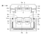
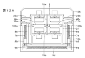
- FIGS. 11A, 11B, 12A, and 12B Modified examples in the case where the present invention is applied to dual conveyance are shown in FIGS. 11A, 11B, 12A, and 12B, respectively.
- the side surface of the upper furnace body 2 and the inner surface of the hood 106 are connected by brackets 22a and 22b.
- brackets 11a, 11b are provided on the side surfaces of the upper furnace body 2.
- the brackets 22a and 22b and the brackets 11a and 11b are provided with a slide structure for absorbing thermal expansion of the upper furnace body 2.
- the ends of the movable columns 8b and 8d of the elevating mechanisms 4b and 4d push up the lower surfaces of the brackets 11a and 11b.
- the hood 106 overlaps the lower casing 104.
- the upper furnace body 2 and the hood 106 are translated upward as shown in FIG. 11B. And maintenance work can be performed from the openings formed on both sides.
- brackets 12a and 12b that connect the inner surface of the hood 106 and the ends of the movable support columns 8b and 8d are used instead of the brackets 11a and 11b in FIGS. 11A and 11B.
- the brackets 22a and 22b and the brackets 12a and 12b are provided with a slide structure for absorbing thermal expansion of the upper furnace body 2.
- the ends of the movable struts 8b and 8d of the elevating mechanisms 4b and 4d push up the lower surfaces of the brackets 12a and 12b.
- the hood 106 overlaps with the lower casing 104.
- the upper furnace body 2 and the hood 106 are translated upward as shown in FIG. 12B. And maintenance work can be performed from the openings formed on both sides.
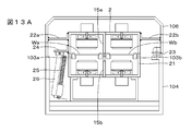
- FIGS. 13A and 13B show a configuration in which a hinge structure opening / closing method is applied to one side of a conventional technique for dual conveyance including an upper bulkhead 15a on the upper furnace side and a lower bulkhead 15b on the lower furnace side.
- the side surfaces of the upper furnace body 2 and the inner surface of the hood 106 are connected by brackets 22a and 22b.
- the upper furnace body 2 and the hood 106 can be rotated by the hinge part 23.
- a bracket 24 is attached to the side surface of the upper furnace body 2 on the side where the hinge portion 23 is not provided.
- a drive mechanism including a rotating shaft 25 and a movable support column 26 is provided, and an opening is formed between the hood 106 and the lower housing 104 by the end of the movable support column 26 pushing up the bracket 24.
- the opening is formed only on one side, there is a problem that maintenance work for the location on the back side becomes troublesome.
- it becomes difficult to perform maintenance work such as cleaning of a conveyance part far from the opening (in the example of FIGS. 13A and 13B, the conveyance conveyor 103b side).
- the openings are formed on both sides, such a problem does not occur.
- the recessed member of the upper partition wall moves obliquely from the upper direction toward the projecting member of the lower partition wall, it is necessary to set a large opening of the recessed member material.
- the effect of preventing temperature interference between the two spaces is reduced by the fitting portion having a low degree of close contact.
- the opening of the recess material of the fitting portion can be made smaller than the case where the one-side hinge structure shown in FIGS. 13A and 13B is adopted, and the effect of preventing the temperature interference of the partition wall is impaired. There is no advantage.
- a chain may be used in addition to the shaft as a rotation transmission mechanism between a plurality of lifting mechanisms.
- the number of lifting mechanisms may be other than the above-described embodiment.
- the present invention can be applied not only to the reflow device but also to a heating device for curing the resin.
- the configurations, methods, processes, shapes, materials, numerical values, and the like given in the above-described embodiments are merely examples, and different configurations, methods, processes, shapes, materials, numerical values, etc. are used as necessary. May be.
- the configurations, methods, steps, shapes, materials, numerical values, and the like of the above-described embodiments can be combined with each other without departing from the gist of the present disclosure.
- the openings can be formed on both sides by translating the furnace body and the hood upward. Therefore, the maintenance work becomes easier as compared with the conventional configuration in which the furnace body and the hood are rotated by the hinge.
Landscapes
- Engineering & Computer Science (AREA)
- Mechanical Engineering (AREA)
- General Engineering & Computer Science (AREA)
- Manufacturing & Machinery (AREA)
- Microelectronics & Electronic Packaging (AREA)
- Electric Connection Of Electric Components To Printed Circuits (AREA)
- Tunnel Furnaces (AREA)
Abstract
上部炉体及びフードを上方に平行移動して搬送方向に沿って両側に開口を形成することによってメインテナンス作業を容易とする。被加熱体を搬送する搬送装置と、搬送装置の上方に設けられ、被加熱体を加熱する上部炉体と、上部炉体及び搬送装置を収納する筐体の一部をなすフードと、上部炉体及びフードを垂直方向に平行移動させる複数の昇降機構と、単一の駆動手段と複数の昇降機構の間に設けられた回転伝達機構部とを備える搬送加熱装置である。
Description
この発明は、例えばプリント基板のリフローを行うリフロー装置に対して適用できる搬送加熱装置に関する。
電子部品又はプリント基板に対して、予めはんだ組成物を供給しておき、リフロー炉の中に基板を搬送コンベアで搬送するリフロー装置が使用されている(例えば特許文献1参照)。リフロー装置は、基板を搬送する搬送コンベアと、この搬送コンベアによって被加熱物例えばプリント基板が供給されるリフロー炉本体とを備えている。リフロー炉は、例えば、搬入口から搬出口に至る搬送経路に沿って、複数のゾーンに分割されており、これらの複数のゾーンがインライン状に配列されている。複数のゾーンは、その機能によって、加熱ゾーン、冷却ゾーンなどの役割を有する。
リフロー炉本体は上部炉体及び下部炉体を有する。例えば上部炉体から基板に対して熱風が吹きつけられ、下部炉体から基板に対して熱風が吹きつけられることによって、はんだ組成物内のはんだを溶融させてプリント基板の電極と電子部品とがはんだ付けされる。リフロー装置では、加熱時の温度を所望の温度プロファイルにしたがって制御することによって、所望のはんだ付けがなされる。
このようなリフロー装置において、内部に付着したフラックスの除去等のメインテナンス作業を行うために、従来では、片側ヒンジ構造で上部炉体及びフード(ケース)を開放可能としていた(例えば特許文献2参照)。作業者は上部炉体及びフードを開放して片側からリフロー装置内に対するメインテナンス作業を行っていた。
従来の構成では片側からのみしかアクセスすることができないので、奥側の箇所に対するメインテナンス作業を行うのに手間がかかっていた。特に二つの搬送コンベアを平行に配置するデュアル搬送構成のリフロー装置の場合では、奥側の搬送コンベアに対するメインテナンス作業を行うことが大変面倒であった。特許文献2に記載のものは、両側にヒンジを設けているので、作業のために開放する側を変えることによってメインテナンス作業が楽とできる。しかしながら、開放する側を変更する場合、上部炉体及びフードを一旦閉じてから再び反対側を開ける作業が必要で作業性が悪く、且つ二つの搬送コンベアを備えたデュアル搬送リフロー装置に対して本技術を適用しても同時にメインテナンスできないといった問題があった。
したがって、この発明の目的は、メインテナンス作業が従来に比して容易となり、作業性を向上することができる搬送加熱装置を提供することにある。
この発明は、被加熱体を搬送する搬送装置と、搬送装置の上方に設けられ、被加熱体を加熱する上部炉体と、炉体及び搬送装置を収納する筐体の一部をなすフードと、炉体及びフードを垂直方向に平行移動させる複数の昇降機構と、単一の駆動手段と複数の昇降機構の間に設けられた回転伝達機構部とを備える搬送加熱装置である。
少なくとも一つの実施形態によれば、炉体及びフードを上方に平行移動することによって両側に開口を形成することができる。したがって、ヒンジによって炉体及びフードを回転させる従来の構成と比較してメインテナンス作業が容易となる。なお、ここに記載された効果は必ずしも限定されるものではなく、本開示中に記載されたいずれの効果であってもよい。また、以下の説明における例示された効果により本開示の内容が限定して解釈されるものではない。
以下、この発明を実施の形態について説明する。なお、説明は、以下の順序で行う。
<1.リフロー装置の一例>
<2.一実施の形態>
<3.変形例>
なお、以下に説明する一実施の形態は、この発明の好適な具体例であり、技術的に好ましい種々の限定が付されているが、この発明の範囲は、以下の説明において、特にこの発明を限定する旨の記載がない限り、これらの実施の形態に限定されないものとする。
<1.リフロー装置の一例>
<2.一実施の形態>
<3.変形例>
なお、以下に説明する一実施の形態は、この発明の好適な具体例であり、技術的に好ましい種々の限定が付されているが、この発明の範囲は、以下の説明において、特にこの発明を限定する旨の記載がない限り、これらの実施の形態に限定されないものとする。
<1.リフロー装置の一例>
図1は、この発明を適用できる従来のリフロー装置101の概略的構成を示す。リフロー装置101は、炉体102と、被加熱物例えば両面に表面実装用電子部品が搭載されたプリント基板(以下、ワークと称する)Wを炉体102内を通過させる搬送コンベア103と、搬送コンベア103の移動経路を規定する回転体105a、105b、105c、105dと、下部筐体104及びフード106を備える。
図1は、この発明を適用できる従来のリフロー装置101の概略的構成を示す。リフロー装置101は、炉体102と、被加熱物例えば両面に表面実装用電子部品が搭載されたプリント基板(以下、ワークと称する)Wを炉体102内を通過させる搬送コンベア103と、搬送コンベア103の移動経路を規定する回転体105a、105b、105c、105dと、下部筐体104及びフード106を備える。
炉体102は、上部炉体及び下部炉体によってワークWを上下から加熱し、加熱後に冷却するためのものである。搬送コンベア103は、シングル搬送の場合は搬送方向に延びる一つの搬送コンベアであり、デュアル搬送の場合は搬送方向に平行して配されている二つの搬送コンベアである。例えば搬送コンベア103として、ローラチェーンが使用されている。リフロー装置101の下部全体を覆う下部筐体104と上部全体を覆うフード106が設けられている。下部筐体104上にフード106が載置される。
ワークWは、搬入口107から炉体102内に搬入された後、搬送コンベア103によって所定速度で矢印方向(図1に向かって左から右方向)へ搬送され、最終的に搬出口108から取り出される。図示しないが、搬入口107の前段には、ワークWを搬入するためのワーク搬入装置が設けられ、搬出口108の後段には、ワークWを外部へ送り出すためのワーク搬出装置が配置されている。
搬入口107から搬出口108に至る搬送経路に沿って、炉体102が例えば9個のゾーンZ1からZ9に順次分割され、これらのゾーンZ1~Z9がインライン状に配列されている。搬入口107側から7個のゾーンZ1~Z7が加熱ゾーンであり、搬出口108側の2個のゾーンZ8及びZ9が冷却ゾーンである。冷却ゾーンZ8及びZ9に関連して強制冷却ユニット(図示しない)が設けられている。なお、ゾーン数は、一例であって、他の個数のゾーンを備えても良い。複数のゾーンZ1~Z9がリフロー時の温度プロファイルにしたがってワークWの温度を制御する。加熱ゾーンZ1~Z7のそれぞれは、それぞれ送風機を含む上部炉体及び下部炉体を有する。
最初の区間が加熱によって温度が上昇する昇温部R1であり、次の区間は温度がほぼ一定のプリヒート(予熱)部R2であり、次の区間がリフロー(リフロー)部R3であり、最後の区間が冷却部R4である。昇温部R1は、常温からプリヒート部R2(例えば150℃~170℃)まで基板を加熱する期間である。プリヒート部R2は、等温加熱を行い、フラックスを活性化し、電極、及びはんだ粉の表面の酸化膜を除去し、また、ワークの加熱ムラをなくすための期間である。リフロー部R3(例えばピーク温度で220℃~240℃)は、はんだが溶融し、接合が完成する期間である。リフロー部R3では、はんだの溶融温度を超える温度まで昇温が必要とされる。最後の冷却部R4は、急速にプリント基板を冷却し、はんだ組成を形成する期間である。なお、無鉛ハンダの場合では、リフロー部における温度は、より高温(例えば240℃~260℃)となる。
かかる構成のリフロー装置101では、昇温部R1の温度制御を、主としてゾーンZ1及びZ2が受け持つ。プリヒート部R2の温度制御は、主としてゾーンZ3、Z4及びZ5が受け持つ。リフロー部R3の温度制御は、ゾーンZ6及びZ7が受け持つ。冷却部R4の温度制御は、ゾーンZ8及びゾーンZ9が受け持つ。
<2.一実施の形態>
上述したリフロー装置101において、炉体102の上部炉体とフード106が上方に平行移動され、炉体102の搬送方向に沿った両側に作業用の開口が形成される。この開口を通じて作業を行い、フラックス除去等のメインテナンス作業がなされる。
上述したリフロー装置101において、炉体102の上部炉体とフード106が上方に平行移動され、炉体102の搬送方向に沿った両側に作業用の開口が形成される。この開口を通じて作業を行い、フラックス除去等のメインテナンス作業がなされる。
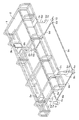
図2及び図3A、図3Bは、一実施の形態の構成を示す。フードフレーム1に対して図示しないが金属板(外板)が貼り付けられてフード106が構成される。フードフレーム1は炉体102の上方全体を覆う屋根状に例えば角柱部材を組み立てたものである。
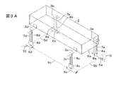
炉体102の上部炉体2(2点鎖線で示す)の両側面にそれぞれ2個の連結部としてのブラケット3a,3b,3c及び3d(これらのブラケットを特に区別する必要がない場合は単にブラケット3と称する)が固定されている。連結部としては板状のものに限らず、棒状のものなどを使用してもよい。なお、図3A及び図3Bではフードフレーム1の図示を省略し、上部炉体2を矩形の箱体として示している。上部炉体2に対してそのワーク搬入側から等距離の位置に2個のブラケット3a及び3cが取り付けられ、そのワーク搬出側から等距離の位置に2個のブラケット3b及び3dが取り付けられる。すなわち、上部炉体2の4隅の近傍にブラケット3が取り付けられる。
ブラケット3は、金属板をL字状に加工して水平板と垂直板が約90度の角度をなすもので、垂直板が上部炉体2の側面と固定されている。ブラケット3の水平板がフードフレーム1に取り付けられる。例えばフードフレーム1の炉体延長方向に延びる2本の角柱部材に対してブラケット3の水平板が取り付けられる。フードフレーム1及び上部炉体2の合計の重量は例えば1.2tonである。さらに、炉体102(上部炉体2)はリフロー動作時に非動作時に比較して数ミリ程度熱膨張する。この炉体102の熱膨張によってブラケット3の位置が変化する。この変化を吸収するために、取付箇所において、フードフレーム1に対してブラケット3の水平板がスライド可能とされている。
一実施の形態では、フードフレーム1及び上部炉体2が垂直方向に昇降するようになされる。図3Aはフードフレーム1及び上部炉体2が通常位置にある状態を示す。図3Bがフードフレーム1及び上部炉体2がメインテナンス位置にある状態を示す。メインテナンス位置ではフードが上方に平行移動され、フードと筐体の間に開口が形成される。この開口を通じてメインテナンス作業を行うことができる。
昇降動作によってフードフレーム1及び上部炉体2が平行移動される。平行移動とはフードフレーム1及び上部炉体2の全ての点が等しい距離移動することである。但し、歯車のバックラッシュ等の誤差に起因して通常生じる程度の相違が存在する場合も平行移動と称する。必要に応じて初期的な調整がなされ、フードフレーム1及び上部炉体2が水平に位置するようになされる。フードフレーム1とブラケット3の連結位置の近傍で、ブラケット3の下側に昇降機構4a,4b,4c,4d(これらの昇降機構を特に区別する必要がない場合は単に昇降機構4と称する)が配置されている。昇降機構4に対して単一の駆動手段としてモータ5が設けられる。モータ5の回転が図示しない制御部によって制御される。
モータ5と昇降機構4との間に、モータ5の駆動力を昇降機構4に伝達するための回転伝達機構部6a,6b,6c,6d(これらの回転伝達機構部を特に区別する必要がない場合は単に回転伝達機構部6と称する)が設けられている。昇降機構4は、台形ねじで構成されたスクリュー軸7a,7b,7c,7d(これらのスクリュー軸を特に区別する必要がない場合は単にスクリュー軸7と称する)と、スクリュー軸7の回転によって昇降する可動支柱8a、8b、8c、8d(これらの可動支柱を特に区別する必要がない場合は単に可動支柱8と称する)を有している。
回転伝達機構部6には回転を伝達するための軸9a,9b,9c,9d(これらの軸を特に区別する必要がない場合は単に軸9と称する)が設けられている。モータ5は、一つの昇降機構例えば昇降機構4aと回転伝達機構部6aを介して結合されている。さらに、昇降機構4dの回転伝達機構部6dに手動で回転力を発生するためのハンドル10が取り付けられている。なお、モータ5及び回転伝達機構部6は下部炉体の下側例えばリフロー装置の底部に設置される。下部炉体から離れるほどリフロー時の炉体の熱の影響を受けにくいので、モータ5及び回転伝達機構部6が熱で故障するおそれを低くできる。
回転伝達機構部6aにおいて、モータ5の回転がスクリュー軸7a、軸9a及び9bに伝達される。モータ5の軸とほぼ同一の延長方向を有する軸9aに対しては軸継手(カップリング)を介して回転力が伝えられる。モータ5の軸と異なる方向のスクリュー軸7a及び軸9bに対してはかさ歯車を介して回転力が伝えられる。軸9aの回転が回転伝達機構部6bに伝達され、軸9bの回転が回転伝達機構部6cに伝達される。なお、かさ歯車は回転伝達機構の一例であり、ウォームギヤ等の他の機構を使用してもよい。
回転伝達機構部6bにおいて、かさ歯車を介して軸9aの回転がスクリュー軸7b及び軸9dに伝達される。回転伝達機構部6cにおいて、かさ歯車を介して軸9bの回転がスクリュー軸7cに伝達される。回転伝達機構部6dにおいて、かさ歯車を介して軸9dの回転がスクリュー軸7dに伝達される。軸9dに代えて軸9cによって回転を伝達するようにしてもよい。4本の軸9が水平面上で矩形を構成し、ねじれ等に対する強度を増すことができる。
上述したように、回転伝達機構部6aにおいて、モータ5の回転がスクリュー軸7a、軸9a及び軸9bに伝達される。そして(軸9a→回転伝達機構部6b(スクリュー軸7b)→軸9d→回転伝達機構部6d(スクリュー軸7d))の経路と、(軸9b→回転伝達機構部6c(スクリュー軸7c))の経路でモータ5の回転が伝達される。軸9a,9b,9dの回転が同期しているので、4本のスクリュー軸7a~7dも同期して回転する。
スクリュー軸と噛み合う台形ねじのナットが可動支柱8に取り付けられている。スクリュー軸7の所定方向の回転によってナットが上昇し、反対方向の回転によってナットが下降するため、スクリュー軸7の回転によって可動支柱8が昇降する。可動支柱8の上側の端部の支持板がブラケット3の水平板の下面に取り付けられている。上述したように、上部炉体2が熱膨張するので、ブラケット3が変位可能に可動支柱8によって支持される。図3A及び図3Bに示すように、スクリュー軸7の回転によって可動支柱8が昇降すると、フードフレーム1及び上部炉体2が昇降する。図3Aが通常位置を示し、図3Bがメインテナンス時の位置を示す。
スクリュー軸7とナットの噛み合わせの構造は、セルフロック機能を有し、スクリュー軸7の回転が静止した時の可動支柱8の位置が保持される。したがって、モータ5及び回転伝達機構部6にブレーキ機構を設ける必要がない。ブレーキ機構を設けないので、例えば停電時にはハンドル10を回転することによって、スクリュー軸を回転させてフードフレーム1及び上部炉体2が昇降させることができる。すなわち、ハンドル10の回転が(回転伝達機構部6d(スクリュー軸7d)→軸9d→回転伝達機構部6b(スクリュー軸7b)→軸9a→回転伝達機構部6a(スクリュー軸7a)→軸9b→回転伝達機構部6c(スクリュー軸7c))の経路で伝達される。軸9a,9b,9dの回転が同期するので、4本のスクリュー軸7a~7dが同期して回転する。
回転伝達機構部6の損傷等の理由によって、4本のスクリュー軸7が同期して回転しない場合にはリフロー装置に損傷が与えられるおそれがある。そこで、可動支柱8にスクリュー軸7の回転を監視するために例えば光学式の回転検出センサを設けるようにしている。スクリュー軸7の回転の検出の代わりに可動支柱8の昇降位置を検出するようにしてもよい。4本のスクリュー軸7が全て回転している場合を正常動作として検出し、スクリュー軸7の1本でも正常に回転していない場合(停止及び回転速度の異常)を異常動作として検出する。異常動作の場合には、モータ5を強制的に停止させる。
図4に示すように、可動支柱8の昇降を検出するために、可動支柱8にセンサドグSDが取り付けられ、可動支柱8の昇降方向と平行し、且つ異なる高さの位置にセンサS1,S2,S3が配されている。センサドグSDがセンサS1,S2,S3と接近すると、光学的な検出動作、磁気的な検出動作又は静電的な検出動作に基づいて検出信号が発生する。さらに、非接触式に限らず、接触式のものを使用してもよい。一例としてマイクロフォトセンサが使用される。センサS1が例えば開始位置に設けられ、センサS3が最大高さの終了位置に設けられ、センサS2がセンサS1及びS2の間に設けられている。なお、図4では、一つの可動支柱8についてのみ示されているが、全ての可動支柱と関連してセンサが同様に設けられている。また、図4では、回転伝達機構部6としてかさ歯車が示されている。
可動支柱8の昇降動作は、駆動手段としてのモータ5によってなされるので、図5に示すように、モータ5の駆動を制御する制御部31に対して全ての可動支柱と関連するセンサS1,S2,S3の検出信号が供給される。制御部31は、マイクロプロセッサを有し、ソフトウェアにしたがってモータ5の回転を制御する。例えば初期位置からモータ5の回転が開始してセンサS1の検出信号が発生すると、モータ5の回転を停止し、可動支柱8の位置を初期位置とする。入力部32から可動支柱8を上昇させる指令が制御部31に供給されると、制御部31はモータ5の回転を開始する。そして、センサS3からの検出信号が得られると、制御部31はモータ5の回転を停止する。制御部31は、センサS1、センサS2及びセンサS3の検出信号同士の時間間隔を測定することによって、可動支柱8の昇降速度を測定することができる。4個の昇降機構の可動支柱8の昇降速度が予め設定した値以上ばらつく場合には、制御部31がモータ5の回転を緊急停止する。なお、図4及び図5に示すモータ5の回転の制御の構成は一例であって、他の構成を使用してもよい。
上述したように、この発明の一実施の形態では、駆動手段としてのモータ5が単一であって、4個の昇降機構4が設けられている。この発明と異なり、各昇降機構にモータを設けることも考えうる構成である。しかしながら、このように別々のモータを設けると、モータ間の同期をとることが難しく軸の噛み込みによる昇降不良が発生し、平行移動ができないおそれが高い。さらに、停電時には全てのモータが停止してしまうので、別々に手動で動かすことになり、平行移動が難しい問題がある。したがって、この発明のように、単一の駆動手段によって駆動する構成によって昇降機構の昇降動作を同期させることができ、また、停電時に手動で駆動することができる利点がある。
「シングル搬送の実施の形態」
さらに、この発明の一実施の形態について図面を参照して説明する。図6A、図6Bは、加熱ゾーンの一つのゾーンを搬送方向と直交する面で切断した場合の断面を搬入口側から見た断面図である。図6A、図6Bに示すように、上部炉体2と下部炉体21の対向間隙内で、ワークWが、搬送コンベア103上に置かれて搬送される。
さらに、この発明の一実施の形態について図面を参照して説明する。図6A、図6Bは、加熱ゾーンの一つのゾーンを搬送方向と直交する面で切断した場合の断面を搬入口側から見た断面図である。図6A、図6Bに示すように、上部炉体2と下部炉体21の対向間隙内で、ワークWが、搬送コンベア103上に置かれて搬送される。
上部炉体2及び下部炉体21により形成される空間内は、雰囲気ガスである例えば窒素(N2)ガスが充満している。なお、雰囲気ガスは窒素(N2)ガスに代えて大気ガスであってもよい。上部炉体2及び下部炉体21は、ワークWに対して熱風(熱せられた雰囲気ガス)を噴出してワークWを加熱する。上部炉体2内には例えばターボファンの構成の送風機と、ヒータと、熱風が通過する多数の小孔を有するパネル(蓄熱部材)からなる加熱ユニットが配されている。
図6Aに示す通常位置では、下部筐体104上にフード106が載置されている。フード106は、フードフレーム1に対して金属板(外板)を貼り付けた構成を有する。パネルの小孔を通過した熱風が、搬送コンベア103によって搬送されるワークWに対して上側から吹きつけられる。下部炉体21内にも同様の加熱ユニットが設けられ、ワークWに対して下側から熱風が吹きつけられる。
メインテナンス時には、昇降機構4によって上部炉体2及びフード106が上方に平行移動され、図6Bに示す位置とされる。この位置において、下部筐体104とフード106との間に形成された両側の開口を通じて内部の清掃等のメインテナンス作業を行うことができる。
「シングル搬送の変形例」
この発明をシングル搬送に適用した場合の変形例を図7A、図7B及び図8A、図8Bにそれぞれ示す。図7A、図7Bに示す構成では、上部炉体2の側面とフード106の内面との間がブラケット22a及び22bによって連結される。ブラケット3(3b,3d)の代わりに、上部炉体2の側面にブラケット11a,11bが設けられている。これらのブラケット22a及び22b並びにブラケット11a,11bには、上部炉体2の熱膨張を吸収するための構成が設けられている。昇降機構4b,4dの可動支柱8b,8dの端部がブラケット11a,11bの下面を押し上げるようになされる。
この発明をシングル搬送に適用した場合の変形例を図7A、図7B及び図8A、図8Bにそれぞれ示す。図7A、図7Bに示す構成では、上部炉体2の側面とフード106の内面との間がブラケット22a及び22bによって連結される。ブラケット3(3b,3d)の代わりに、上部炉体2の側面にブラケット11a,11bが設けられている。これらのブラケット22a及び22b並びにブラケット11a,11bには、上部炉体2の熱膨張を吸収するための構成が設けられている。昇降機構4b,4dの可動支柱8b,8dの端部がブラケット11a,11bの下面を押し上げるようになされる。
図7Aの通常位置では下部筐体104上にフード106が重なっており、メインテナンス時には図7Bに示すように、上部炉体2及びフード106が上方に平行移動される。そして、両側に形成された開口からメインテナンス作業を行うことができる。
図8A、図8Bに示す構成では、図7A、図7Bのブラケット11a,11bの代わりにフード106の内面と可動支柱8b,8dの間を連結するブラケット12a,12bが使用される。これらのブラケット22a及び22b並びにブラケット12a,12bには、上部炉体2の熱膨張を吸収するための構成が設けられている。昇降機構4b,4dの可動支柱8b,8dの端部がブラケット12a,12bの下面を押し上げるようになされる。
図8Aの通常位置では下部筐体104上にフード106が重なっており、メインテナンス時には図8Bに示すように、上部炉体2及びフード106が上方に平行移動される。そして、両側に形成された開口からメインテナンス作業を行うことができる。
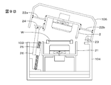
図9A、図9Bは、従来の構成を示す。上部炉体2の側面とフード106の内面との間がブラケット22a及び22bによって連結される。ヒンジ部23によって上部炉体2及びフード106が回転可能とされる。ヒンジ部23が設けられていない側の上部炉体2の側面にブラケット24が取り付けられる。回転軸25及び可動支柱26からなる駆動機構が設けられ、可動支柱26の端部がブラケット24を押し上げることによってフード106と下部筐体104の間に開口が形成される。かかる従来の構成では、片側のみに開口が形成されるので、奥側の箇所に対するメインテナンス作業が面倒となる問題がある。この発明では両側に開口が形成されるのでかかる問題が生じない。
「デュアル搬送の実施の形態」
さらに、この発明をデュアル搬送に適用した場合の構成について説明する。図10A、図10Bは、加熱ゾーンの一つのゾーンを搬送方向と直交する面で切断した場合の断面を搬入口側から見た断面図である。
さらに、この発明をデュアル搬送に適用した場合の構成について説明する。図10A、図10Bは、加熱ゾーンの一つのゾーンを搬送方向と直交する面で切断した場合の断面を搬入口側から見た断面図である。
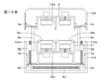
上部炉体2及び下部炉体21内に、第1の搬送コンベア103aと第2の搬送コンベア103bとが平行して設けられている。これらの搬送コンベア間に設けられた隔壁によって、炉体内の空間が第1の搬送コンベア103a側の空間と、第2の搬送コンベア103b側の空間に仕切られている。隔壁は、上部炉体側の上部隔壁15aと下部炉体側の下部隔壁15bとにより構成されている。
隔壁は、例えば、断熱作用を有するものである。上部隔壁15a及び下部隔壁15bは、例えばそれぞれ内部にガスが導入される空間を有する2枚の金属板状体(例えば、ステンレス板等)が対向するものである。上部隔壁15a及び下部隔壁15bの対向する対向端部の一方は先細り形状とされ、他方は開放形状とされている。先細り形状とされた一方の対向端部は、開放形状とされた他方の対向端部に嵌合/分離可能とされている。
上部炉体2、下部炉体21、上部隔壁15a及び下部隔壁15bによって形成される搬送コンベア103a側の空間では、上部炉体2内の加熱ユニット及び下部炉体21内の加熱ユニットがワークWaに対して熱風(熱せられた雰囲気ガス)を噴出してワークWaを加熱する。上部炉体2及び下部炉体21には例えばターボファンの構成の送風機と、ヒータと、熱風が通過する多数の小孔を有するパネル(蓄熱部材)からなる加熱ユニットがそれぞれ設けられている。搬送コンベア103b側の空間においては同様の加熱ユニットによってワークWbが加熱される。
図10Aに示す通常位置では、下部筐体104上にフード106が載置されている。フード106は、フードフレーム1に対して金属板(外板)を貼り付けた構成を有する。パネルの小孔を通過した熱風が、搬送コンベア103a及び103bによって搬送されるワークWa及びWbに対して上側及び下側から吹きつけられる。
メインテナンス時には、昇降機構4によって上部炉体2及びフード106が上方に平行移動され、図10Bに示す位置とされる。この位置において、下部筐体104とフード106との間に形成された両側の開口を通じて内部の清掃等のメインテナンス作業を行うことができる。
「デュアル搬送の変形例」
この発明をデュアル搬送に適用した場合の変形例を図11A、図11B及び図12A、図12Bにそれぞれ示す。図11A、図11Bに示す構成では、上部炉体2の側面とフード106の内面との間がブラケット22a及び22bによって連結される。ブラケット3(3b,3d)の代わりに、上部炉体2の側面にブラケット11a,11bが設けられている。これらのブラケット22a及び22b並びにブラケット11a,11bには、上部炉体2の熱膨張を吸収するためのスライド構成が設けられている。昇降機構4b,4dの可動支柱8b,8dの端部がブラケット11a,11bの下面を押し上げるようになされる。
この発明をデュアル搬送に適用した場合の変形例を図11A、図11B及び図12A、図12Bにそれぞれ示す。図11A、図11Bに示す構成では、上部炉体2の側面とフード106の内面との間がブラケット22a及び22bによって連結される。ブラケット3(3b,3d)の代わりに、上部炉体2の側面にブラケット11a,11bが設けられている。これらのブラケット22a及び22b並びにブラケット11a,11bには、上部炉体2の熱膨張を吸収するためのスライド構成が設けられている。昇降機構4b,4dの可動支柱8b,8dの端部がブラケット11a,11bの下面を押し上げるようになされる。
図11Aの通常位置では下部筐体104上にフード106が重なっており、メインテナンス時には図11Bに示すように、上部炉体2及びフード106が上方に平行移動される。そして、両側に形成された開口からメインテナンス作業を行うことができる。
図12A、図12Bに示す構成では、図11A、図11B中のブラケット11a,11bの代わりにフード106の内面と可動支柱8b,8dの端部間を連結するブラケット12a,12bが使用される。これらのブラケット22a及び22b並びにブラケット12a,12bには、上部炉体2の熱膨張を吸収するためのスライド構成が設けられている。昇降機構4b,4dの可動支柱8b,8dの端部がブラケット12a,12bの下面を押し上げるようになされる。
図12Aの通常位置では下部筐体104上にフード106が重なっており、メインテナンス時には図12Bに示すように、上部炉体2及びフード106が上方に平行移動される。そして、両側に形成された開口からメインテナンス作業を行うことができる。
図13A、図13Bは、上部炉体側の上部隔壁15aと下部炉体側の下部隔壁15bとを備えたデュアル搬送に従来技術の片側にヒンジ構造の開閉方式を適用した構成を示す。上部炉体2の側面とフード106の内面との間がブラケット22a及び22bによって連結される。ヒンジ部23によって上部炉体2及びフード106が回転可能とされる。ヒンジ部23が設けられていない側の上部炉体2の側面にブラケット24が取り付けられる。回転軸25及び可動支柱26からなる駆動機構が設けられ、可動支柱26の端部がブラケット24を押し上げることによってフード106と下部筐体104の間に開口が形成される。かかる従来の構成では、片側にのみ開口が形成されるので、奥側の箇所に対するメインテナンス作業が面倒となる問題がある。特にデュアル搬送のようなマルチ搬送型の場合では、開口から遠い側の搬送部(図13A、図13Bの例では搬送コンベア103bの側)の清掃等のメインテナンス作業を行うことが大変となる。この発明では両側に開口が形成されるのでかかる問題が生じない。
さらに、図13A、図13Bに示す片側ヒンジ構造では斜め上から上部隔壁の凹部材が下部隔壁の凸部材に向かって移動するために、凹部材の開口を大きく設定する必要があり、その結果、密着の程度の低い嵌合部によって二つの空間の間の温度干渉を防止する効果が減少する。この発明では平行移動であるので、嵌合部の凹部材の開口を図13A、図13Bに示す片側ヒンジ構造を採用した場合と比較して小さくすることができ、隔壁の温度干渉防止効果が損なわれない利点がある。
<3.変形例>
以上、本開示の実施の形態について具体的に説明したが、上述の各実施の形態に限定されるものではなく、本開示の技術的思想に基づく各種の変形が可能である。例えば、この発明は、複数の昇降機構間の回転伝達機構としては軸以外にチェーンを使用するようにしてもよい。また、昇降機構の個数は、上述した実施の形態以外の数を設けてもよい。さらに、リフロー装置に限らず、樹脂の硬化のための加熱装置等に対しても適用できる。また、上述の実施の形態において挙げた構成、方法、工程、形状、材料及び数値などはあくまでも例に過ぎず、必要に応じてこれと異なる構成、方法、工程、形状、材料及び数値などを用いてもよい。また、上述の実施の形態の構成、方法、工程、形状、材料及び数値などは、本開示の主旨を逸脱しない限り、互いに組み合わせることが可能である。
以上、本開示の実施の形態について具体的に説明したが、上述の各実施の形態に限定されるものではなく、本開示の技術的思想に基づく各種の変形が可能である。例えば、この発明は、複数の昇降機構間の回転伝達機構としては軸以外にチェーンを使用するようにしてもよい。また、昇降機構の個数は、上述した実施の形態以外の数を設けてもよい。さらに、リフロー装置に限らず、樹脂の硬化のための加熱装置等に対しても適用できる。また、上述の実施の形態において挙げた構成、方法、工程、形状、材料及び数値などはあくまでも例に過ぎず、必要に応じてこれと異なる構成、方法、工程、形状、材料及び数値などを用いてもよい。また、上述の実施の形態の構成、方法、工程、形状、材料及び数値などは、本開示の主旨を逸脱しない限り、互いに組み合わせることが可能である。
少なくとも一つの実施形態によれば、炉体及びフードを上方に平行移動することによって両側に開口を形成することができる。したがって、ヒンジによって炉体及びフードを回転させる従来の構成と比較してメインテナンス作業が容易となる。
W,Wa,Wb・・・ワーク
1・・・フードフレーム
2・・・上部炉体
3,3a~3d・・・ブラケット
4,4a~4d・・・昇降機構
5・・・モータ
6,6a~6d・・・回転伝達機構部
7,7a~7d・・・スクリュー軸
8,8a~8d・・・可動支柱
9,9a~9d・・・軸
10・・・ハンドル
11a,11b・・・ブラケット
12a,12b・・・ブラケット
15a・・・下部隔壁
15b・・・上部隔壁
101・・・リフロー装置
102・・・炉体
103,103a,103b・・・搬送コンベア
106・・・フード
1・・・フードフレーム
2・・・上部炉体
3,3a~3d・・・ブラケット
4,4a~4d・・・昇降機構
5・・・モータ
6,6a~6d・・・回転伝達機構部
7,7a~7d・・・スクリュー軸
8,8a~8d・・・可動支柱
9,9a~9d・・・軸
10・・・ハンドル
11a,11b・・・ブラケット
12a,12b・・・ブラケット
15a・・・下部隔壁
15b・・・上部隔壁
101・・・リフロー装置
102・・・炉体
103,103a,103b・・・搬送コンベア
106・・・フード
Claims (8)
- 被加熱体を搬送する搬送装置と、
前記搬送装置の上方に設けられ、前記被加熱体を加熱する上部炉体と、
前記上部炉体及び前記搬送装置を収納する筐体の一部をなすフードと、
前記上部炉体及び前記フードを垂直方向に平行移動させる複数の昇降機構と、
単一の駆動手段と前記複数の昇降機構の間に設けられた回転伝達機構部と
を備える搬送加熱装置。 - 前記搬送装置が配置される空間を挟んで前記上部炉体と対向する下部炉体が設けられた
請求項1に記載の搬送加熱装置。 - 前記上部炉体の搬送方向に沿った両側にそれぞれ少なくとも二つの前記昇降機構が設けられ、
前記昇降機構の間に前記回転伝達機構部の軸がそれぞれ設けられた
請求項1又は2に記載の搬送加熱装置。 - 前記昇降機構が前記駆動手段によって回転されるスクリュー軸と、
前記スクリュー軸に噛み合って昇降する台形ねじのナットに取り付けられた可動支柱とからなる
請求項1乃至3のいずれかに記載の搬送加熱装置。 - 前記搬送装置が搬送方向に沿って並列に設けられた複数の搬送コンベアを有する
請求項1乃至4のいずれかに記載の搬送加熱装置。 - 前記複数の搬送コンベアのそれぞれの間に隔壁が設けられ、前記隔壁が上部隔壁及び下部隔壁が接続位置で分離又は嵌合するようになされた
請求項5に記載の搬送加熱装置。 - 前記上部炉体及び前記フードを連結部によって連結し、前記昇降機構によって前記上部炉体及び前記フードを一体に昇降させるようにした
請求項1に記載の搬送加熱装置。 - 前記フード及び前記連結部の一方が前記上部炉体の熱膨張によってスライドするようになされた
請求項7に記載の搬送加熱装置。
Applications Claiming Priority (2)
| Application Number | Priority Date | Filing Date | Title |
|---|---|---|---|
| JP2016-072756 | 2016-03-31 | ||
| JP2016072756A JP6471114B2 (ja) | 2016-03-31 | 2016-03-31 | 搬送加熱装置 |
Publications (1)
| Publication Number | Publication Date |
|---|---|
| WO2017170930A1 true WO2017170930A1 (ja) | 2017-10-05 |
Family
ID=59964797
Family Applications (1)
| Application Number | Title | Priority Date | Filing Date |
|---|---|---|---|
| PCT/JP2017/013396 Ceased WO2017170930A1 (ja) | 2016-03-31 | 2017-03-30 | 搬送加熱装置 |
Country Status (2)
| Country | Link |
|---|---|
| JP (1) | JP6471114B2 (ja) |
| WO (1) | WO2017170930A1 (ja) |
Cited By (2)
| Publication number | Priority date | Publication date | Assignee | Title |
|---|---|---|---|---|
| US11007591B2 (en) * | 2017-06-05 | 2021-05-18 | Senju Metal Industry Co., Ltd. | Reflow soldering apparatus having independently openable main bodies |
| US20230147525A1 (en) * | 2021-11-09 | 2023-05-11 | Ersa Gmbh | Soldering system |
Citations (2)
| Publication number | Priority date | Publication date | Assignee | Title |
|---|---|---|---|---|
| JP2007173494A (ja) * | 2005-12-22 | 2007-07-05 | Yokota Technica:Kk | リフロー半田付け方法及びリフロー半田付け装置 |
| JP2014170906A (ja) * | 2013-03-05 | 2014-09-18 | Tamura Seisakusho Co Ltd | リフロー装置 |
-
2016
- 2016-03-31 JP JP2016072756A patent/JP6471114B2/ja active Active
-
2017
- 2017-03-30 WO PCT/JP2017/013396 patent/WO2017170930A1/ja not_active Ceased
Patent Citations (2)
| Publication number | Priority date | Publication date | Assignee | Title |
|---|---|---|---|---|
| JP2007173494A (ja) * | 2005-12-22 | 2007-07-05 | Yokota Technica:Kk | リフロー半田付け方法及びリフロー半田付け装置 |
| JP2014170906A (ja) * | 2013-03-05 | 2014-09-18 | Tamura Seisakusho Co Ltd | リフロー装置 |
Cited By (2)
| Publication number | Priority date | Publication date | Assignee | Title |
|---|---|---|---|---|
| US11007591B2 (en) * | 2017-06-05 | 2021-05-18 | Senju Metal Industry Co., Ltd. | Reflow soldering apparatus having independently openable main bodies |
| US20230147525A1 (en) * | 2021-11-09 | 2023-05-11 | Ersa Gmbh | Soldering system |
Also Published As
| Publication number | Publication date |
|---|---|
| JP6471114B2 (ja) | 2019-02-13 |
| JP2017177207A (ja) | 2017-10-05 |
Similar Documents
| Publication | Publication Date | Title |
|---|---|---|
| CN103056473B (zh) | 一种连续式真空焊接炉及其焊接方法 | |
| US11007591B2 (en) | Reflow soldering apparatus having independently openable main bodies | |
| US20110041558A1 (en) | Heat treatment apparatus for tempering glass | |
| JP6471114B2 (ja) | 搬送加熱装置 | |
| JP6715651B2 (ja) | 搬送加熱装置 | |
| JP5279606B2 (ja) | はんだ付け装置 | |
| CN102192643B (zh) | 节能铬酸盐平面炉 | |
| JP7169161B2 (ja) | 搬送加熱装置 | |
| JP2519013B2 (ja) | リフロ―半田付装置 | |
| JP2014170906A (ja) | リフロー装置 | |
| JP2018082112A (ja) | 搬送加熱装置 | |
| JP2013117328A (ja) | 加熱炉 | |
| TWI748803B (zh) | 烤箱自動化開關機械裝置 | |
| JP2005116575A (ja) | リフロー装置 | |
| JP2007281271A (ja) | 半田加熱装置及び方法 | |
| JP7623223B2 (ja) | 搬送加熱装置及び温度制御方法 | |
| CN207104200U (zh) | 门端框焊接系统 | |
| CN114932316B (zh) | 一种板材损伤修复装置 | |
| JP7569348B2 (ja) | 搬送加熱装置 | |
| CN119216845B (zh) | 一种用于铝制件生产的冷焊加工装置 | |
| CN115287434B (zh) | 防撞梁用的网带加热炉和防撞梁热处理方法 | |
| JP2005156311A (ja) | 自動寸法測定装置 | |
| JP7028835B2 (ja) | 加熱炉及び搬送加熱装置 | |
| JP2008226980A (ja) | リフロー装置 | |
| JP4792745B2 (ja) | リフロー炉 |
Legal Events
| Date | Code | Title | Description |
|---|---|---|---|
| NENP | Non-entry into the national phase |
Ref country code: DE |
|
| 121 | Ep: the epo has been informed by wipo that ep was designated in this application |
Ref document number: 17775464 Country of ref document: EP Kind code of ref document: A1 |
|
| 122 | Ep: pct application non-entry in european phase |
Ref document number: 17775464 Country of ref document: EP Kind code of ref document: A1 |