WO2017170798A1 - 物体認識装置及び物体認識方法 - Google Patents
物体認識装置及び物体認識方法 Download PDFInfo
- Publication number
- WO2017170798A1 WO2017170798A1 PCT/JP2017/013117 JP2017013117W WO2017170798A1 WO 2017170798 A1 WO2017170798 A1 WO 2017170798A1 JP 2017013117 W JP2017013117 W JP 2017013117W WO 2017170798 A1 WO2017170798 A1 WO 2017170798A1
- Authority
- WO
- WIPO (PCT)
- Prior art keywords
- target
- image
- radar
- detected
- information
- Prior art date
- Legal status (The legal status is an assumption and is not a legal conclusion. Google has not performed a legal analysis and makes no representation as to the accuracy of the status listed.)
- Ceased
Links
Images



Classifications
-
- G—PHYSICS
- G01—MEASURING; TESTING
- G01S—RADIO DIRECTION-FINDING; RADIO NAVIGATION; DETERMINING DISTANCE OR VELOCITY BY USE OF RADIO WAVES; LOCATING OR PRESENCE-DETECTING BY USE OF THE REFLECTION OR RERADIATION OF RADIO WAVES; ANALOGOUS ARRANGEMENTS USING OTHER WAVES
- G01S13/00—Systems using the reflection or reradiation of radio waves, e.g. radar systems; Analogous systems using reflection or reradiation of waves whose nature or wavelength is irrelevant or unspecified
- G01S13/86—Combinations of radar systems with non-radar systems, e.g. sonar, direction finder
- G01S13/867—Combination of radar systems with cameras
-
- G—PHYSICS
- G01—MEASURING; TESTING
- G01S—RADIO DIRECTION-FINDING; RADIO NAVIGATION; DETERMINING DISTANCE OR VELOCITY BY USE OF RADIO WAVES; LOCATING OR PRESENCE-DETECTING BY USE OF THE REFLECTION OR RERADIATION OF RADIO WAVES; ANALOGOUS ARRANGEMENTS USING OTHER WAVES
- G01S13/00—Systems using the reflection or reradiation of radio waves, e.g. radar systems; Analogous systems using reflection or reradiation of waves whose nature or wavelength is irrelevant or unspecified
- G01S13/88—Radar or analogous systems specially adapted for specific applications
- G01S13/93—Radar or analogous systems specially adapted for specific applications for anti-collision purposes
- G01S13/931—Radar or analogous systems specially adapted for specific applications for anti-collision purposes of land vehicles
-
- B—PERFORMING OPERATIONS; TRANSPORTING
- B60—VEHICLES IN GENERAL
- B60R—VEHICLES, VEHICLE FITTINGS, OR VEHICLE PARTS, NOT OTHERWISE PROVIDED FOR
- B60R21/00—Arrangements or fittings on vehicles for protecting or preventing injuries to occupants or pedestrians in case of accidents or other traffic risks
-
- G—PHYSICS
- G01—MEASURING; TESTING
- G01S—RADIO DIRECTION-FINDING; RADIO NAVIGATION; DETERMINING DISTANCE OR VELOCITY BY USE OF RADIO WAVES; LOCATING OR PRESENCE-DETECTING BY USE OF THE REFLECTION OR RERADIATION OF RADIO WAVES; ANALOGOUS ARRANGEMENTS USING OTHER WAVES
- G01S7/00—Details of systems according to groups G01S13/00, G01S15/00, G01S17/00
- G01S7/02—Details of systems according to groups G01S13/00, G01S15/00, G01S17/00 of systems according to group G01S13/00
- G01S7/41—Details of systems according to groups G01S13/00, G01S15/00, G01S17/00 of systems according to group G01S13/00 using analysis of echo signal for target characterisation; Target signature; Target cross-section
-
- G—PHYSICS
- G08—SIGNALLING
- G08G—TRAFFIC CONTROL SYSTEMS
- G08G1/00—Traffic control systems for road vehicles
- G08G1/16—Anti-collision systems
Definitions
- the present disclosure relates to an object recognition device and an object recognition method, and more particularly to an object recognition device and an object recognition method applied to a vehicle in which a radar device and an imaging device are mounted as object detection sensors.
- a reflection point satisfying a predetermined condition is grouped as a reflection point reflected by the same object, and the grouping is performed.
- An apparatus for recognizing an object existing around a host vehicle using information on a plurality of reflection points has been proposed (see, for example, Patent Document 1).
- a right end reflection point and a left end reflection point are extracted from a plurality of reflection points detected by a radar apparatus, and an object is represented based on the right end reflection point and the left end reflection point.
- the representative point to be calculated is calculated.
- the amount of change of each of the right end reflection point, the left end reflection point, and the representative point is calculated, and when the change amount satisfies a predetermined condition, the estimated width of the object is calculated based on the right end reflection point and the left end reflection point. Based on the estimated width, the reflection point grouping is corrected. Thereby, an erroneous grouping process by determining a reflection point group straddling a plurality of objects as one object is prevented.
- the present disclosure has been made in view of the above problems, and an object thereof is to provide an object recognition device and an object recognition method that can quickly determine that a radar device has detected a plurality of objects as one object. To do.
- This disclosure employs the following means in order to solve the above problems.
- reflection points detected by a radar device are grouped, and a radar target detected using the grouped plurality of reflection points and an image detected using an image captured by an imaging device
- An object recognition device for recognizing an object existing around the host vehicle based on a target, and a reflection point acquisition unit that acquires reflection point information that is information on the plurality of grouped reflection points;
- the image target detected by the imaging device includes an image single target that is not detected by the radar device, the reflection point information acquired by the reflection point acquisition unit and the information of the image target
- an object determination unit that determines that the radar device has detected a plurality of the objects as one object.
- a plurality of grouped reflection point information is acquired, and based on the acquired reflection point information and image target information, it is determined that the radar apparatus has detected a plurality of objects as one object.
- the radar apparatus may erroneously detect the plurality of vehicles as one object.
- a plurality of vehicles running in parallel at a distance are detected as a plurality of objects by the imaging device, and a plurality of reflection points grouped as reflections on one object reach a plurality of image targets. If so, it can be determined that the radar device detects a plurality of objects as one object.
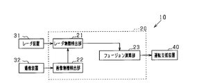
- FIG. 1 is a block diagram showing a schematic configuration of a driving support system
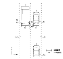
- FIG. 2 is a diagram for explaining object detection and fusion by the radar device 31.
- FIG. 3 is a diagram for explaining an embodiment of image multi-connection.
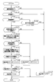
- FIG. 4 is a flowchart showing the processing procedure of the multi-join determination process.
- FIG. 5 is a flowchart showing a processing procedure of image multi-connection processing.
- FIG. 6 is a block diagram illustrating a schematic configuration of a driving support system according to another embodiment.
- the driving support system 10 of the present embodiment shown in FIG. 1 is mounted on a vehicle, recognizes an object existing around the host vehicle, and executes various driving supports based on the recognition result of the object.
- an auto cruise control system ACC
- PCS system
- the driving support system 10 includes an object recognition device 20, various sensors, and a driving support device 40.
- the object recognition device 20 is a computer having a CPU, a ROM, a RAM, an I / O, and the like, and the CPU recognizes an object existing around the host vehicle by executing a program installed in the ROM. To achieve each function.
- the object recognition device 20 is connected to a radar device 31 and an imaging device 32, which are object detection sensors, and receives detection results of objects from these sensors.
- the radar device 31 is a detection device that detects an object by transmitting an electromagnetic wave as a transmission wave and receiving the reflected wave.
- a known millimeter wave that uses a high-frequency signal in the millimeter wave band as a transmission wave. It consists of radar.
- the radar device 31 is attached to the front end portion of the host vehicle, and scans a region extending over a predetermined angle range from the front of the vehicle around the optical axis with a radar signal. Further, the radar device 31 creates distance measurement data based on the time from transmission of electromagnetic waves toward the front of the vehicle until reception of the reflected wave, and sequentially outputs the created distance measurement data to the object recognition device 20. .
- the distance measurement data includes information on the direction in which the object exists, the distance to the object, and the relative speed of the object.
- the radar device 31 includes a transmission / reception unit 31a that transmits electromagnetic waves and receives reflected waves, and a control unit 31b.
- the control unit 31b detects a plurality of reflection points based on the reflected waves received by the transmission / reception unit 31a, and groups the detected plurality of reflection points into segments based on a predetermined condition. Thereby, the target which exists ahead of the own vehicle is recognized as one target.
- a representative point representing the target is calculated for each target recognized by the grouping process from a plurality of reflection points for each grouped segment.
- the representative point may be one point selected from a plurality of reflection points in the segment (for example, an intermediate point, a left end point or a right end point among the plurality of reflection points), or a left end point and a right end point It is good also as a midpoint.
- the control unit 31b calculates the relative position, the relative speed, and the direction of the target recognized by the grouping process as distance measurement data using the distance, speed, and direction of the plurality of reflection points with respect to the host vehicle.
- the object recognition device 20 outputs the reflection point information as distance measurement data together with the coordinates of the representative point.
- the reflection point information includes distance information from a representative point of each reflection point in a plurality of reflection points for each segment.
- the imaging device 32 is an in-vehicle camera, and is composed of, for example, a monocular camera such as a CCD camera, a CMOS image sensor, or a near infrared camera.
- the imaging device 32 is attached to a predetermined height in the center of the vehicle in the vehicle width direction, and images an area that extends in a predetermined angle range toward the front of the vehicle from an overhead viewpoint. Further, the imaging device 32 sequentially outputs the captured image data to the object recognition device 20.
- the object recognition device 20 sequentially inputs the distance measurement data of the radar device 31 and the image data of the imaging device 32, and recognizes the object using the input data.
- the object recognition device 20 includes a radar target detection unit 21, an image target detection unit 22, and a fusion calculation unit 23.
- the radar target detection unit 21 inputs distance measurement data from the radar device 31 and identifies an object detected using the input distance measurement data as a radar target. Further, the relative position of the radar target with respect to the host vehicle is specified by applying the position information of the identified radar target to the xy plane.
- the vehicle width direction of the host vehicle is the x axis and the vehicle length direction is the y axis.
- the position information of the representative point P is applied to the xy plane, and the radar search area is set as an area representing the position of the radar target in the area including the representative point P.
- the radar search area is set as an area having an error assumed based on the detection characteristics of the radar device 31.
- the radar target detection unit 21 functions as a reflection point acquisition unit.
- the image target detection unit 22 identifies an object detected by analyzing the image data as an image target, and applies the position information of the identified image target to the xy plane, so that the image target for the host vehicle is detected. Specify the relative position.
- the image target detection unit 22 performs pattern matching on the image target using a predetermined pattern, and detects the type of the object detected by the imaging device 32, for example, one of a vehicle, a pedestrian, and a bicycle. Is identified. Further, the image target detection unit 22 generates azimuth angle information as information representing the position of the target recognized in the image with respect to the host vehicle.
- the image target detection unit 22 detects a vehicle as an object existing in front of the host vehicle, the line segment connecting the left end of the preceding vehicle and the reference point 0, the right end of the preceding vehicle, The angle formed by the line connecting the reference point 0 is calculated as the image angle width W ⁇ .
- Reference point 0 represents the position of the vehicle.
- the image target detection unit 22 sets an image search area as an area representing the position of the image target.
- the image search area is set as an area having an error assumed based on the detection characteristics of the imaging device 32.
- the fusion calculation unit 23 is a radar that satisfies a predetermined positional relationship determined to belong to the same object in the radar target acquired from the radar target detection unit 21 and the image target acquired from the image target detection unit 22.
- the radar target information and the image target information of the combination are combined (fused) to generate a fusion target as a combined target.
- a combination in which an overlapping portion exists between the radar search area set by the radar target detection unit 21 and the image search area set by the image target detection unit 22 is extracted, and the extracted combination The radar target and the image target are determined as the same object.
- the distance detected by the radar device 31 (hereinafter referred to as “millimeter wave distance”) is set as the distance to the fusion target, and the distance information of the radar target and the azimuth information of the image target are used.
- the horizontal position and width of the fusion target are specified.
- the lateral position is a relative position in the vehicle width direction (x-axis direction) with respect to the reference point 0.
- Information about the generated fusion target is output to the driving support device 40.
- the driving support device 40 inputs the fusion target information generated by the fusion calculation unit 23, and controls driving devices by controlling, for example, a brake device, a steering device, a seat belt driving device, an alarm device, etc. based on the input information. Perform various controls for.
- a sensor that detects the presence of an object by radio waves such as a millimeter wave radar
- radio waves such as a millimeter wave radar
- a plurality of vehicles running in parallel may be erroneously detected as one object.
- driving support such as follow-up traveling control and collision avoidance control for the preceding vehicle cannot be appropriately performed.
- R1 to R3 indicate a plurality of reflection points recognized as belonging to one object by the grouping process
- P indicates a representative point of the plurality of reflection points R1 to R3.
- Q1 indicates the image recognition position of the preceding vehicle 51 recognized by the imaging device 32
- Q2 indicates the image recognition position of the adjacent vehicle 52.
- the millimeter wave output of the radar device 31 becomes one unit.
- a fusion target is generated based on the positional relationship between the image target and the radar target.
- the radar target of the representative point P and the image target of the adjacent vehicle 52 are fused.
- the preceding vehicle 51 becomes an image alone, and no fusion target is generated for the preceding vehicle 51. In such a case, there is a concern that the recognition reliability of the preceding vehicle 51 cannot be sufficiently secured, or that the preceding vehicle 51 may not be a target for driving support depending on the control specifications.
- the radar device 31 when there is an image target that is a target that is not detected by the radar device 31 among the image targets detected by the imaging device 32, the reflection point information of a plurality of reflection points, and the image Based on the target information, it is determined that the radar device 31 has detected a plurality of objects as one object. If the radar device 31 determines that a plurality of objects are erroneously detected as one object, the distance information of the radar target and the lateral position information of the image target are combined for the single image target. By doing so, the recognition accuracy of an object detected only by an image alone is improved.
- the radar device 31 detects the target. Fusion with the radar target.
- image multi-connection the process of combining two image targets with one radar target is referred to as “image multi-connection” or simply “multi-connection”.
- FIG. 3 assumes a scene in which the preceding vehicle 51 and the adjacent vehicle 52 are running in parallel in front of the host vehicle 50, as in FIG. R1 to R3, Q1 and Q2 in FIG. 3 are the same as those in FIG.
- the fusion calculation unit 23 acquires information about the plurality of reflection points R1 to R3 detected by the radar device 31 from the radar target detection unit 21, and the host vehicle 50 out of the acquired plurality of reflection points R1 to R3.
- the right end reflection point, which is the reflection point located at the right end in the width direction, and the left end reflection point, which is the reflection point located at the left end, are extracted. Then, based on the positional relationship between at least one of the extracted right end reflection point and left end reflection point and the single image target, it is determined whether or not the radar device 31 detects a plurality of objects as one object.
- the fusion calculation unit 23 functions as an object determination unit, an information combination unit, a vehicle condition determination unit, a distance determination unit, and a vehicle width calculation unit.
- the fusion calculation unit 23 combines the millimeter-wave distance d, which is the distance information of the object detected by the radar device 31, and the image angle width W ⁇ , which is the lateral position information of the object detected by the imaging device 32, to obtain the preceding vehicle.
- a fusion target corresponding to 51 is generated.
- the process of FIG. 4 is executed by the fusion calculation unit 23 of the object recognition device 20 every predetermined control cycle.
- step S100 it is determined whether or not there is an image target among the image targets detected by the imaging device 32.
- the process proceeds to step S101, and it is determined whether or not the image single target is a target existing on the course of the host vehicle 50.
- the travel lane line of the own lane 61 can be recognized by the imaging device 32, the determination is made based on whether or not the image target is on the own lane 61.
- the predicted course of the host vehicle 50 is calculated, and the determination is made based on whether or not there is a single image target on the predicted course. To do.
- step S101 If an affirmative determination is made in step S101, the process proceeds to step S102, and it is determined whether or not the image single target on the own vehicle path is a long-distance target that is a predetermined distance or more away from the own vehicle 50. When it is determined that the target is not a long-distance target separated by a predetermined distance or more, the process proceeds to step S103, and it is determined whether or not the image is a single target image of the previous multi-join candidate.
- the multi-connection candidate is a target that is a candidate for fusion of one radar target and each of a plurality of image targets.
- step S104 When it is determined that the image alone target on the vehicle path was the previous multi-join candidate, and when the image alone target on the vehicle path is determined to be a long-distance target separated by a predetermined distance or more Then, the process proceeds to step S104.
- step S104 it is determined whether or not there is a fusion target (also referred to as “FSN target”) in the vicinity of the image single target.
- a fusion target also referred to as “FSN target”
- the image target used for the fusion with the radar target is within a predetermined range from the single image target. Specifically, the difference between the distance between the image target used for the fusion with the radar target and the single image target is less than the predetermined value ⁇ d, and the difference between the lateral positions is less than the predetermined value ⁇ x.
- the fusion target here is a combination of a radar target and an image target in which an overlap portion exists between the radar search region and the image search region. In FIG.
- step S104 the target generated based on the radar target of the representative point P and the image target of the adjacent vehicle 52 corresponds to the fusion target in step S104. If an affirmative determination is made in step S104, the process proceeds to step S105, and the left end reflection point and the right end reflection point are extracted from the plurality of reflection points that are grouped when the representative point P is set.
- step S106 it is determined whether or not the object corresponding to the single image target is reflected by the electromagnetic wave transmitted from the radar device 31 (hereinafter referred to as “millimeter wave reflection”).
- millimeter wave reflection the electromagnetic wave transmitted from the radar device 31
- the left end SL of the image single target is to the left of the right end reflection point, or the right end SR of the image single target is to the right of the left end reflection point
- the object corresponding to the image single target It is determined that there was millimeter wave reflection. If an affirmative determination is made in step S106, the process proceeds to step S107.
- the image target is a vehicle
- the millimeter wave distance d detected by the radar device 31 and the azimuth angle of the image target detected by the imaging device 32 are detected.
- the vehicle width WA of the single image target is calculated using the image angle width W ⁇ that is information.
- step S108 it is determined whether or not the vehicle width WA of the single image target is within a predetermined range.
- the vehicle width WA calculated using the millimeter wave distance d and the image angle width W ⁇ is distorted, and is actually present. It is a numerical value that cannot be obtained.
- step S108 when the vehicle width WA calculated using the distance information of the radar target and the information regarding the image width of the single image target is out of a predetermined range, the single image object is displayed. The fusion between the target and the radar target is not performed or is difficult to be performed.
- step S108 the process proceeds to step S109, and the multi-join determination counter CA is incremented.
- step S108 the multi-bond determination counter CA is decremented.
- step S111 it is determined whether or not the multi-bond determination counter CA is greater than or equal to a determination value. If the multi-bond determination counter CA is greater than or equal to the determination value, the process proceeds to step S112, and the multi-bond determination flag is turned on.
- This multi-coupling determination flag is a flag indicating whether or not a plurality of objects are detected as one object by the radar device 31 and is turned on when it is determined that the object is detected as one object. On the other hand, if CA ⁇ determination value, this routine is temporarily terminated. Further, when there is no single image target on the own vehicle path, and when the single image target is a target that suddenly appears near the own vehicle 50, the multi-join determination flag is turned off in step S113.
- step S201 it is determined whether or not the multi-join determination flag is on.
- the process proceeds to step S202 on the condition that the multi-join determination flag is on, and the millimeter wave distance d is acquired from the radar target detection unit 21 and the image target detection unit 22 receives the image as azimuth angle information of the single image target. Obtain the angular width W ⁇ .
- step S203 the acquired millimeter wave distance d and the image angle width W ⁇ are combined, and the distance, the lateral position, and the object width with respect to the host vehicle 50 are calculated for the object detected only by the image on the host vehicle path. Then, this routine ends.
- a plurality of reflection point information grouped as reflections on one object is acquired, and based on the acquired reflection point information and image target information, the radar device 31 detects that the plurality of objects are detected as one object. to decide. Even when a plurality of vehicles running in parallel at a distance have reflections and the radar device 31 erroneously detects a plurality of vehicles as one object, the imaging device 32 detects a plurality of objects, and one object In the case where a plurality of reflection points grouped as reflections on a plurality of image targets reach a plurality of image targets, it can be determined that the radar device 31 detects a plurality of objects as one object.
- the radar apparatus 31 it is possible to accurately determine whether or not the radar apparatus 31 has detected a plurality of objects as one object. Further, by making a determination based on the combination with the image target information, it is possible to quickly determine after an object is detected by the radar device 31 and the imaging device 32.
- the radar device 31 uses a plurality of reflection points grouped as reflections on a single object, based on the positional relationship between at least one of the right end reflection point and the left end reflection point, and the single image target. It was set as the structure which determines having detected this object as one object. According to such a configuration, it is possible to accurately determine that a plurality of reflection points grouped as reflections on one object reach the single image target.
- the radar device 31 Based on the reflection point information and the image target information, when it is determined that the radar device 31 has detected a plurality of objects as one object, the azimuth angle information of the single image target and the distance information of the radar target are combined. Thus, the fusion target corresponding to the single image target is generated. Since the representative point P of the radar target is calculated from a plurality of reflection points grouped as reflections on one object, when it is determined that the radar device 31 has detected a plurality of objects as one object, The representative point P is presumed to be affected by a single image target. In view of this point, it is possible to improve the recognition accuracy of the object corresponding to the image single target by fusing the single image target and the radar target.
- the radar apparatus 31 sets a plurality of objects on the condition that there is a combination of a radar target and an image target that satisfy a predetermined positional relationship determined to belong to the same object within a predetermined range from the single image target. It was set as the structure which determines whether it detected as an object. If there is an image single target and it is determined that the radar device 31 has detected a plurality of objects as one object, it is assumed that an FSN target exists in the vicinity of the image single target. The In view of this point, by adopting the above configuration, it is possible to reduce the risk of erroneous determination when determining whether or not to perform multiple image coupling.
- It is configured to determine whether or not the radar device 31 has detected a plurality of objects as one object on the condition that the single image target is a target existing on the course of the host vehicle.
- the radar device 31 is configured to determine whether or not the radar device 31 has detected a plurality of objects as one object on the condition that the distance of the single image target from the host vehicle 50 is a predetermined distance or more.
- the radar device 31 is likely to erroneously detect a plurality of objects as one object, which is a target that exists far away, and a target that suddenly appears at a short distance may be a ghost. In view of this point, it is possible to suppress erroneous determination by specifying a determination target of whether or not a plurality of objects are detected as one object by the radar device 31 as a long-distance target.
- the azimuth angle information of the image single target and the radar target distance information are combined to calculate the vehicle width WA of the other vehicle, and the calculated vehicle width WA is predetermined.
- the radar apparatus 31 determines that a plurality of objects are detected as one object on the condition that the range is within the range.
- the vehicle width WA obtained by fusing the image single target and the radar target becomes a value that is not possible in practice, the distance between the image single target and the radar target is too far, and the same It is determined that the object cannot be considered.
- the radar target detection unit 21 may function as an object determination unit.
- the radar target detection unit 21 of the object recognition device 20 inputs distance measurement data including reflection point information from the radar device 31 and from the image target detection unit 22. Get an image target.
- the radar target detection unit 21 determines that a plurality of objects are detected as one object by the radar device 31 based on the acquired reflection point information and image target information.
- the grouping correction is performed for a plurality of reflection points that are grouped as reflections by one object. For example, in FIG.
- the reflection points R1 and R2 that overlap with Q2 that is the image recognition position of the adjacent vehicle 52 are grouped as one segment, and the reflection point R3 that overlaps Q1 that is the image recognition position of the preceding vehicle 51 is 1 Group as one segment.
- a representative point is set for each grouping, and information regarding the representative point and the image target information acquired from the image target detecting unit 22 are output to the fusion calculating unit 23.
- the fusion calculation unit 23 generates a fusion target by fusing the information about the representative points and the image target information. In the case of FIG. 3, a fusion target corresponding to the preceding vehicle 51 and a fusion target corresponding to the adjacent vehicle 52 are generated.
- the fusion calculation unit 23 may generate the fusion target using the information about one representative point and the image target information without correcting the grouping.
- the control unit 31b of the radar device 31 may function as an object determination unit.
- the inter-vehicle distance between the host vehicle 50 and the preceding vehicle 51 is controlled to a constant distance. It is good also as a structure which suppresses acceleration of the own vehicle 50 or implements slow deceleration in inter-vehicle distance control. With such a configuration, it is possible to secure a time until the radar device 31 can detect the preceding vehicle 51, and it is possible to generate a fusion target before approaching the preceding vehicle 51.
- a plurality of objects are detected as one object by the radar device 31 based on the reflection point information and the image target information on the condition that there is a single image target existing on the own vehicle path.
- the present invention is not limited to the image single target existing on the own vehicle route, and the above determination process may be performed when the image single target exists on the adjacent lane 62, for example.
- the single image target is a long-distance target separated from the host vehicle 50 by a predetermined distance or more
- a plurality of objects are detected by the radar device 31 based on the reflection point information and the image target information.
- the above-described determination process may be performed regardless of whether or not the single image target is a long-distance target.
- each said component is conceptual and is not limited to the said embodiment.
- the functions of one component may be realized by being distributed to a plurality of components, or the functions of a plurality of components may be realized by one component.
Landscapes
- Engineering & Computer Science (AREA)
- Radar, Positioning & Navigation (AREA)
- Remote Sensing (AREA)
- Physics & Mathematics (AREA)
- General Physics & Mathematics (AREA)
- Computer Networks & Wireless Communication (AREA)
- Mechanical Engineering (AREA)
- Electromagnetism (AREA)
- Radar Systems Or Details Thereof (AREA)
- Traffic Control Systems (AREA)
Abstract
物体認識装置(20)は、レーダ装置(31)で検出された反射点をグルーピングし、該グルーピングした複数の反射点を用いて検出したレーダ物標と、撮像装置(32)で撮影した画像を用いて検出した画像物標とに基づいて、自車両の周囲に存在する物体を認識する。前記物体認識装置は、前記グルーピングされた複数の反射点に関する情報である反射点情報を取得する反射点取得部と、前記撮像装置により検出した画像物標の中に前記レーダ装置では検出されていない物標である画像単独物標を含む場合に、前記反射点取得部で取得した反射点情報と前記画像物標の情報とに基づいて、前記レーダ装置が複数の物体を一物体として検出したことを判定する物体判定部と、を備える。
Description
本出願は、2016年3月31日に出願された日本出願番号2016-072803号に基づくもので、ここにその記載内容を援用する。
本開示は、物体認識装置及び物体認識方法に関し、詳しくは、物体検知センサとしてレーダ装置及び撮像装置が搭載された車両に適用される物体認識装置及び物体認識方法に関する。
従来、ミリ波レーダやレーザレーダ等のレーダ装置で受信した反射波に基づき検出された複数の反射点のうち、所定の条件を満たす反射点を同一物体で反射した反射点としてグルーピングし、そのグルーピングした複数の反射点の情報を用いて、自車両の周囲に存在する物体を認識する装置が提案されている(例えば、特許文献1参照)。
特許文献1に記載の装置では、レーダ装置で検出した複数の反射点の中から、右端の反射点及び左端の反射点を抽出するとともに、右端反射点及び左端反射点に基づいて、物体を代表する代表点を算出する。また、右端反射点、左端反射点及び代表点のそれぞれの変化量を算出し、それら変化量が所定条件を満たす場合に、右端反射点及び左端反射点に基づいて物体の推定幅を算出する。そして、その推定幅に基づいて、反射点のグルーピングの修正を行う。これにより、複数の物体に跨る反射点群を1つの物体として判断することによる誤ったグルーピング処理を防止するようにしている。
特許文献1の装置では、右端反射点、左端反射点及び代表点のそれぞれの変化量を見ており、物体の推定幅を算出するまでにはある程度の時間を要する。そのため、例えば遠方に走行している並走車に追い付く場合に、物体を検出した初期に反射点のグルーピングの修正を行うことが困難である。また、誤ったグルーピングによる物体検出結果を、例えば先行車両に対する追従走行制御や衝突回避制御等の運転支援に用いることによって、運転支援を適切に実施できないことが懸念される。
本開示は上記課題に鑑みなされたものであり、レーダ装置が複数の物体を一物体として検出したことを速やかに判断することができる物体認識装置及び物体認識方法を提供することを一つの目的とする。
本開示は、上記課題を解決するために、以下の手段を採用した。
本開示の第一の態様において、レーダ装置で検出された反射点をグルーピングし、該グルーピングした複数の反射点を用いて検出したレーダ物標と、撮像装置で撮影した画像を用いて検出した画像物標とに基づいて、自車両の周囲に存在する物体を認識する物体認識装置であって、前記グルーピングされた複数の反射点に関する情報である反射点情報を取得する反射点取得部と、前記撮像装置により検出した画像物標の中に前記レーダ装置では検出されていない物標である画像単独物標を含む場合に、前記反射点取得部で取得した反射点情報と前記画像物標の情報とに基づいて、前記レーダ装置で複数の前記物体を一物体として検出したことを判定する物体判定部と、を備える。
上記構成では、グルーピングされた複数の反射点情報を取得し、その取得した反射点情報と画像物標情報とに基づいて、レーダ装置で複数の物体を一物体として検出したことを判断する。遠方で並走している複数の車両で反射があった場合、レーダ装置では、それらの複数の車両を1つの物体として誤検出することがある。このとき、遠方で並走している複数の車両について、撮像装置で複数の物体として検出しており、かつ1つの物体での反射としてグルーピングした複数の反射点が複数の画像物標に及んでいれば、レーダ装置で複数の物体を一物体として検出していると判断できる。こうした点に着目し、上記構成とすることにより、レーダ装置で複数の物体を一物体として検出したか否かを精度良く判定することができる。また、画像物標情報との組み合わせによって判断する構成とすることにより、レーダ装置、撮像装置で物体が検出された後、レーダ装置で複数の物体を一物体として検出したか否かを速やかに判定することができる。
本開示についての上記目的およびその他の目的、特徴や利点は、添付の図面を参照しながら下記の詳細な記述により、より明確になる。その図面は、
図1は、運転支援システムの概略構成を示すブロック図であり、
図2は、レーダ装置31による物体検出及びフュージョンを説明する図であり、
図3は、画像多結合の実施態様を説明するための図であり、
図4は、多結合判定処理の処理手順を示すフローチャートであり、
図5は、画像多結合処理の処理手順を示すフローチャートであり、
図6は、他の実施形態の運転支援システムの概略構成を示すブロック図である。
以下、実施形態を図面に基づいて説明する。なお、以下の各実施形態相互において、互いに同一もしくは均等である部分には、図中、同一符号を付しており、同一符号の部分についてはその説明を援用する。
図1に示す本実施形態の運転支援システム10は、車両に搭載され、自車両の周囲に存在する物体を認識するとともに、その物体の認識結果に基づいて各種の運転支援を実行する。これにより、例えば自車両と同一車線上を走行する車両に追従して走行するオートクルーズコントロールシステム(ACC)や、物体との衝突を回避又は衝突被害を軽減するための各種制御を行うプリクラッシュセーフティシステム(PCS)等として機能する。運転支援システム10は、図1に示すように、物体認識装置20と各種センサと運転支援装置40とを備えている。
物体認識装置20は、CPU、ROM、RAM、I/O等を備えたコンピュータであり、CPUが、ROMにインストールされているプログラムを実行することで、自車両の周囲に存在する物体を認識するための各機能を実現する。物体認識装置20は、物体検知センサであるレーダ装置31及び撮像装置32にそれぞれ接続されており、これらセンサから物体の検出結果を入力する。
レーダ装置31は、送信波として電磁波を送信し、その反射波を受信することで物体を検知する探知装置であり、本実施形態では、ミリ波帯の高周波信号を送信波とする公知のミリ波レーダで構成されている。レーダ装置31は、自車両の前端部に取り付けられており、光軸を中心に車両前方に向かって所定の角度範囲に亘って広がる領域をレーダ信号により走査する。また、レーダ装置31は、車両前方に向けて電磁波を送信してから反射波を受信するまでの時間に基づき測距データを作成し、その作成した測距データを物体認識装置20に逐次出力する。測距データには、物体が存在する方位、物体までの距離及び物体の相対速度に関する情報が含まれている。
具体的には、レーダ装置31は、電磁波の送信及び反射波の受信を行う送受信部31aと、制御部31bとを備えている。制御部31bは、送受信部31aで受信した反射波に基づき複数の反射点を検出するとともに、その検出した複数の反射点を所定の条件に基づきセグメントにグルーピングする。これにより、自車両の前方に存在する物標を1つの物標として認識する。また、グルーピングしたセグメント毎の複数の反射点から、グルーピング処理によって認識した物標毎に、物標を代表する代表点を算出する。代表点は、セグメント内の複数の反射点の中から選択された1つの点(例えば、複数の反射点のうちの中間点、左端点又は右端点)としてもよいし、あるいは左端点と右端点との中点としてもよい。また、制御部31bは、複数の反射点の自車両に対する距離、速度及び方位を用いて、グルーピング処理によって認識した物標の相対位置、相対速度及び方位を測距データとして算出する。物体認識装置20には、代表点の座標と共に反射点情報が測距データとして出力される。反射点情報には、セグメント毎の複数の反射点における各反射点の代表点からの距離情報が含まれている。
撮像装置32は車載カメラであり、例えばCCDカメラ、CMOSイメージセンサ、近赤外線カメラ等の単眼カメラで構成されている。撮像装置32は、車両の車幅方向中央の所定高さに取り付けられており、車両前方へ向けて所定角度範囲で広がる領域を俯瞰視点から撮影する。また、撮像装置32は、その撮影した画像データを物体認識装置20に逐次出力する。
物体認識装置20は、レーダ装置31の測距データ及び撮像装置32の画像データを逐次入力し、その入力したデータを用いて物体を認識する。物体認識装置20は、レーダ物標検出部21と、画像物標検出部22と、フュージョン演算部23とを備えている。
レーダ物標検出部21は、レーダ装置31から測距データを入力するとともに、その入力した測距データを用いて検出した物体をレーダ物標として識別する。また、識別したレーダ物標の位置情報をxy平面に当てはめることにより、レーダ物標の自車両に対する相対位置を特定する。なお、本実施形態では、自車両の車幅方向をx軸、車長方向をy軸としている。本実施形態では、代表点Pの位置情報をxy平面に当てはめ、代表点Pを含む領域に、レーダ物標の位置を表す領域としてレーダ探索領域を設定する。レーダ探索領域は、レーダ装置31の検出特性に基づき想定される誤差を持たせた領域として設定される。本実施形態では、レーダ物標検出部21が反射点取得部として機能する。
画像物標検出部22は、画像データを解析することによって検出された物体を画像物標として識別し、識別した画像物標の位置情報をxy平面に当てはめることにより、自車両に対する画像物標の相対位置を特定する。また、画像物標検出部22は、画像物標に対して、予め定められたパターンを用いてパターンマッチングを行い、撮像装置32が検出した物体の種別、例えば車両、歩行者及び自転車のいずれかであるかを識別する。さらに、画像物標検出部22は、画像で認識した物標の自車両に対する位置を表す情報として方位角情報を生成する。例えば、画像物標検出部22は、自車両の前方に存在する物体として車両を検出している場合には、その前方車両の左端と基準点0とを結ぶ線分と、前方車両の右端と基準点0とを結ぶ線分とがなす角度を画像角度幅Wφとして算出する。基準点0は自車両の位置を表す。画像物標検出部22は、画像物標の位置を表す領域として画像探索領域を設定する。画像探索領域は、撮像装置32の検知特性に基づき想定される誤差を持たせた領域として設定される。
フュージョン演算部23は、レーダ物標検出部21から取得したレーダ物標及び画像物標検出部22から取得した画像物標の中に、同一物体に属すると判断される所定の位置関係を満たすレーダ物標と画像物標との組み合わせがある場合に、その組み合わせのレーダ物標情報と画像物標情報とを結合(フュージョン)して、結合物標としてのフュージョン物標を生成する。本実施形態では、レーダ物標検出部21で設定したレーダ探索領域と、画像物標検出部22で設定した画像探索領域とに重複部分が存在している組み合わせを抽出し、その抽出された組み合わせのレーダ物標及び画像物標を同一物体と判定する。
また、レーダ装置31で検出した距離(以下、「ミリ波距離」と言う。)をフュージョン物標までの距離に設定するとともに、レーダ物標の距離情報及び画像物標の方位角情報を用いて、フュージョン物標の横位置及び横幅を特定する。なお、横位置とは、基準点0に対する車幅方向(x軸方向)の相対位置である。生成したフュージョン物標に関する情報は運転支援装置40に出力される。こうしたフュージョン処理により、レーダ装置31及び撮像装置32のそれぞれの特性を生かすことで物体の認識精度を向上させている。
運転支援装置40は、フュージョン演算部23で生成したフュージョン物標情報を入力し、入力した情報に基づいて、例えばブレーキ装置やステアリング装置、シートベルト駆動装置、警報装置等を制御することで運転支援のための各種制御を実行する。
ここで、ミリ波レーダ等のように電波により物体の存在を検出するセンサは、センサの分解限界により、自車両の前方において特に遠方で並走する複数の車両を分離して検出することが困難であり、並走する複数の車両を1つの物体として誤検知することがある。また、複数の物体を1つの物体として誤検出した場合には物体の認識精度の低下を招くこととなり、先行車両に対する追従走行制御や衝突回避制御等の運転支援を適切に実施できないことが懸念される。
例えば、図2に示すように、自車両50の前方に自車線61上を走行する先行車両51が存在し、隣接車線62上を走行する隣接車両52(例えば大型車両)と先行車両51とが並走している場合を考える。図2中、R1~R3は、グルーピング処理によって1つの物体に属すると認識された複数の反射点を示し、Pは、複数の反射点R1~R3の代表点を示す。Q1は、撮像装置32で認識した先行車両51の画像認識位置を示し、Q2は、隣接車両52の画像認識位置を示す。
先行車両51及び隣接車両52の両方から、反射波を送受信部31aで受信したにも関わらず、誤ったグルーピング処理が行われ、これによりレーダ装置31のミリ波出力が1台分となった場合、画像物標は2つであるのに対し、レーダ物標は1つとなる。このとき、画像物標とレーダ物標との位置関係に基づきフュージョン物標が生成される。図2では、代表点Pのレーダ物標と、隣接車両52の画像物標とがフュージョンされる。一方、先行車両51は画像単独となり、先行車両51についてフュージョン物標は生成されない。かかる場合、先行車両51の認識信頼度を十分に確保できなかったり、あるいは制御仕様によっては先行車両51が運転支援の制御対象とならなかったりすることが懸念される。
そこで本実施形態では、撮像装置32により検出した画像物標の中に、レーダ装置31では検出されていない物標である画像単独物標がある場合、複数の反射点の反射点情報と、画像物標情報とに基づいて、レーダ装置31で複数の物体を一物体として検出したことを判定することとしている。そして、レーダ装置31で複数の物体を一物体として誤検出していると判定された場合には、画像単独物標について、レーダ物標の距離情報と画像単独物標の横位置情報とを結合することにより、画像単独でしか検出されていない物体の認識精度を向上させるようにしている。つまり、本来であれば、レーダ物標とのフュージョンが行われない画像単独物標について、レーダ装置31で複数の物体を一物体として検出したと判定された場合には、レーダ装置31で検出されているレーダ物標とフュージョンさせる。なお、1つのレーダ物標に対して2つの画像物標をそれぞれ結合させる処理を、以下では「画像多結合」又は単に「多結合」という。
以下に、本実施形態の画像多結合について図3を用いて説明する。なお、図3は、図2と同様、自車両50の前方において先行車両51と隣接車両52とが並走している場面を想定している。図3中のR1~R3、Q1及びQ2については図2と同じである。
フュージョン演算部23は、レーダ装置31で検出している複数の反射点R1~R3に関する情報をレーダ物標検出部21から取得し、取得した複数の反射点R1~R3の中から、自車両50の幅方向において右端に位置する反射点である右端反射点、及び左端に位置する反射点である左端反射点を抽出する。そして、それら抽出した右端反射点及び左端反射点の少なくとも一方と、画像単独物標との位置関係に基づいて、レーダ装置31において複数の物体を1つの物体として検出しているか否かを判定する。なお、本実施形態では、フュージョン演算部23が物体判定部、情報結合部、車両条件判定部、距離判定部及び車幅算出部として機能する。
具体的には、図3では、複数の反射点R1~R3のうち、R3が右端反射点となり、R2が左端反射点となる。これらのうち、右端反射点R3は、自車両50の横方向において先行車両51の画像認識位置Q1と重複している。また、複数の反射点R1~R3をグルーピングして代表点Pを算出していることから、代表点Pの情報には先行車両51の影響が及んでいると言える。そこで、フュージョン演算部23では、レーダ装置31で検出した物体の距離情報であるミリ波距離dと、撮像装置32で検出した物体の横位置情報である画像角度幅Wφとを結合し、先行車両51に対応するフュージョン物標を生成する。
次に、多結合判定処理の処理手順について、図4のフローチャートを用いて説明する。図4の処理は、物体認識装置20のフュージョン演算部23で所定の制御周期毎に実行される。
図4において、ステップS100では、撮像装置32により検出した画像物標の中に画像単独物標があるか否かを判定する。画像単独物標がある場合にはステップS101へ進み、その画像単独物標が、自車両50の進路上に存在する物標であるか否かを判定する。ここでは、自車線61の走行区画線を撮像装置32で認識できている場合には、画像単独物標が自車線61上にあるか否かによって判定する。また、自車線61の走行区画線を撮像装置32で認識できていない場合には、例えば、自車両50の予測進路を算出し、その予測進路上に画像単独物標があるか否かによって判定する。
ステップS101で肯定判定された場合にはステップS102へ進み、自車進路上の画像単独物標が、自車両50から所定距離以上離れた物標である遠距離物標か否かを判定する。所定距離以上離れた遠距離物標でないと判定された場合にはステップS103へ進み、前回の多結合候補の画像単独物標であるか否かを判定する。なお、多結合候補とは、1つのレーダ物標と、複数の画像物標のそれぞれとをフュージョンさせるための候補とされた物標である。自車進路上の画像単独物標が前回の多結合候補であったと判定された場合、及び自車進路上の画像単独物標が所定距離以上離れた遠距離物標であると判定された場合にはステップS104へ進む。
ステップS104では、画像単独物標の近傍にフュージョン物標(「FSN物標」とも言う。)があるか否かを判定する。ここでは、レーダ物標とのフュージョンに用いた画像物標が、画像単独物標から所定範囲内に存在しているか否かを判定する。具体的には、レーダ物標とのフュージョンに用いた画像物標と、画像単独物標との距離の差分が所定値Δd未満であって、かつ横位置の差分が所定値Δx未満である場合に、画像単独物標の近傍にFSN物標があるものと判定する。なお、ここでいうフュージョン物標は、レーダ探索領域と画像探索領域とに重複部分が存在しているレーダ物標と画像物標との組み合わせである。図3では、代表点Pのレーダ物標と、隣接車両52の画像物標とに基づき生成した物標が、ステップS104でのフュージョン物標に相当する。ステップS104で肯定判定されると、ステップS105へ進み、代表点Pを設定する際にグルーピング処理された複数の反射点の中から、左端反射点及び右端反射点を抽出する。
続くステップS106では、画像単独物標に対応する物体において、レーダ装置31から送信した電磁波の反射(以下、「ミリ波反射」という。)があったか否かを判定する。ここでは、画像単独物標の左端SLが右端反射点よりも左にあるか、又は画像単独物標の右端SRが左端反射点よりも右にある場合に、画像単独物標に対応する物体でミリ波反射があったと判定する。ステップS106で肯定判定されるとステップS107へ進み、画像単独物標が車両である場合には、レーダ装置31により検出したミリ波距離dと、撮像装置32により検出した画像単独物標の方位角情報である画像角度幅Wφとを用いて、画像単独物標の車両幅WAを算出する。
続くステップS108では、画像単独物標の車両幅WAが所定範囲内か否かを判定する。ここで、画像単独物標とレーダ物標との距離が離れすぎている場合には、ミリ波距離dと画像角度幅Wφとを用いて算出した車両幅WAに歪みが生じ、実際にはあり得ない数値となる。この点に着目し、ステップS108では、レーダ物標の距離情報と画像単独物標の画像幅に関する情報とを用いて算出した車両幅WAが予め定めた所定範囲から外れる場合には、画像単独物標とレーダ物標とのフュージョンを実施しないか、又は実施されにくくしている。具体的には、ステップS108で肯定判定された場合にはステップS109へ進み、多結合判定カウンタCAをインクリメントする。一方、ステップS108で否定判定された場合には、多結合判定カウンタCAをデクリメントする。
続くステップS111では、多結合判定カウンタCAが判定値以上であるか否かを判定する。多結合判定カウンタCAが判定値以上である場合には、ステップS112へ進み、多結合判定フラグをオンにする。この多結合判定フラグは、レーダ装置31で複数の物体を一物体として検出したか否かを表すフラグであり、一物体として検出したと判定された場合にオンにされる。一方、CA<判定値である場合には、一旦本ルーチンを終了する。また、自車進路上に画像単独物標がない場合、画像単独物標が自車両50の近くに突如現れた物標である場合には、ステップS113で多結合判定フラグがOFFされる。
次に、画像単独物標とレーダ物標とをフュージョンする画像多結合処理について、図5を用いて説明する。この処理は、物体認識装置20のフュージョン演算部23で所定の制御周期毎に実行される。
図5において、ステップS201では、多結合判定フラグがオンか否かを判定する。多結合判定フラグがオンであることを条件にステップS202へ進み、レーダ物標検出部21からミリ波距離dを取得するとともに、画像単独物標の方位角情報として画像物標検出部22から画像角度幅Wφを取得する。続くステップS203では、取得したミリ波距離d及び画像角度幅Wφを結合し、自車進路上において画像のみで検出されている物体について、自車両50に対する距離、横位置及び物体幅を算出する。そして本ルーチンを終了する。
以上詳述した本実施形態によれば、次の優れた効果が得られる。
1つの物体での反射としてグルーピングされた複数の反射点情報を取得し、その取得した反射点情報と画像物標情報とに基づいて、レーダ装置31で複数の物体を一物体として検出したことを判断する。遠方で並走している複数の車両で反射があり、レーダ装置31で複数の車両を1つの物体として誤検出した場合でも、撮像装置32で複数の物体を検出しており、かつ1つの物体での反射としてグルーピングした複数の反射点が複数の画像物標に及んでいる場合には、レーダ装置31で複数の物体を一物体として検出していると判断することができる。したがって、上記構成とすることにより、レーダ装置31で複数の物体を一物体として検出したか否かを精度良く判定することができる。また、画像物標情報との組み合わせによって判断することにより、レーダ装置31、撮像装置32で物体が検出された後、速やかに判定することができる。
具体的には、1つの物体での反射としてグルーピングした複数の反射点のうちの右端反射点及び左端反射点の少なくとも一方と、画像単独物標との位置関係に基づいて、レーダ装置31で複数の物体を一物体として検出したことを判定する構成とした。こうした構成によれば、1つの物体での反射としてグルーピングした複数の反射点が画像単独物標に及んでいることを精度良く判断することができる。
反射点情報と画像物標情報とに基づき、レーダ装置31で複数の物体を一物体として検出したと判定された場合に、画像単独物標の方位角情報とレーダ物標の距離情報とを結合して、画像単独物標に対応するフュージョン物標を生成する構成とした。レーダ物標の代表点Pは、1つの物体での反射としてグルーピングした複数の反射点から算出しているため、レーダ装置31で複数の物体を一物体として検出したと判定されている場合には、代表点Pには画像単独物標の影響が及んでいるものと推測される。この点に鑑み、画像単独物標とレーダ物標とをフュージョンさせることにより、画像単独物標に対応する物体の認識精度を向上させることができる。
画像単独物標から所定範囲内に、同一物体に属すると判断される所定の位置関係を満たすレーダ物標と画像物標との組み合わせがあることを条件に、レーダ装置31で複数の物体を一物体として検出したか否かを判定する構成とした。画像単独物標が存在し、かつレーダ装置31で複数の物体を一物体として検出したと判定される状況であれば、画像単独物標の近傍にFSN物標が存在しているものと推測される。この点に鑑み上記構成とすることにより、画像多結合を行うか否かの判定に際し、誤判定のリスクを低減することができる。
画像単独物標が自車両の進路上に存在する物標であることを条件に、レーダ装置31で複数の物体を一物体として検出したか否かを判定する構成とした。画像多結合を行う画像候補を自車進路上の画像物標に特定することにより、誤判定を抑制しつつ、運転支援を行うに当たって重要度の高い車両の認識精度を高めることができる。
画像単独物標の自車両50からの距離が所定距離以上であることを条件に、レーダ装置31で複数の物体を一物体として検出したか否かを判定する構成とした。レーダ装置31で複数の物体を一物体として誤検出しやすいのは遠方に存在する物標であり、近距離で突如現れた物標はゴーストの可能性がある。この点に鑑み、レーダ装置31で複数の物体を一物体として検出したか否かの判定対象を遠距離物標に特定することにより、誤判定を抑制することができる。
画像単独物標が他車両である場合に、画像単独物標の方位角情報とレーダ物標の距離情報とを結合して他車両の車両幅WAを算出し、その算出した車両幅WAが所定範囲内であることを条件に、レーダ装置31で複数の物体を一物体として検出したと判定する構成とした。画像単独物標とレーダ物標とをフュージョンさせて求めた車両幅WAが、実際にはあり得ない値となった場合、画像単独物標とレーダ物標との距離が離れすぎており、同一物体であるとみなすことができないと判断される。この点に鑑み、上記構成とすることにより、画像多結合を行うか否かの判定において誤判定のリスクを低減することができる。
(他の実施形態)
本開示は上記の実施形態に限定されず、例えば以下のように実施されてもよい。
本開示は上記の実施形態に限定されず、例えば以下のように実施されてもよい。
・上記実施形態では、フュージョン演算部23が物体判定部として機能する構成について説明したが、レーダ物標検出部21が物体判定部として機能する構成としてもよい。具体的には、図6に示すように、物体認識装置20のレーダ物標検出部21は、レーダ装置31から、反射点情報を含む測距データを入力するとともに、画像物標検出部22から画像物標を取得する。また、レーダ物標検出部21は、その取得した反射点情報と画像物標の情報とに基づいて、レーダ装置31で複数の物体を一物体として検出したことを判定する。そして、レーダ装置31で複数の物体を一物体として検出した場合には、1つの物体での反射としてグルーピングした複数の反射点についてグルーピングの修正を行う。例えば、図3では、隣接車両52の画像認識位置であるQ2と重複する反射点R1,R2を1つのセグメントとしてグルーピングし、先行車両51の画像認識位置であるQ1と重複する反射点R3を1つのセグメントとしてグルーピングする。また、グルーピング毎に代表点を設定し、代表点に関する情報及び画像物標検出部22から取得した画像物標情報をフュージョン演算部23に出力する。フュージョン演算部23では、代表点に関する情報と画像物標情報とをフュージョンさせてフュージョン物標を生成する。図3の場合では、先行車両51に対応するフュージョン物標と、隣接車両52に対応するフュージョン物標とが生成される。
・図6の構成において、グルーピングの修正を行わずに、フュージョン演算部23では、1つの代表点に関する情報と画像物標情報とを用いてフュージョン物標を生成してもよい。また、レーダ装置31の制御部31bが物体判定部として機能する構成としてもよい。
・反射点情報と画像物標情報とに基づき、レーダ装置31で複数の物体を一物体として検出したと判定された場合に、自車両50と先行車両51との車間距離を一定距離に制御する車間距離制御において自車両50の加速を抑制又は緩減速を実施する構成としてもよい。こうした構成とすることにより、レーダ装置31が先行車両51を検出できるまでの時間を確保することができ、先行車両51に接近する前にフュージョン物標を生成することが可能となる。
・上記実施形態では、自車進路上に存在する画像単独物標が存在することを条件に、反射点情報と画像物標情報とに基づきレーダ装置31で複数の物体を一物体として検出したことを判定する構成としたが、自車進路上に存在する画像単独物標に限らず、例えば画像単独物標が隣接車線62上に存在する場合に上記判定処理を実施する構成としてもよい。
・上記実施形態では、画像単独物標が、自車両50から所定距離以上離れた遠距離物標であることを条件に、反射点情報と画像物標情報とに基づきレーダ装置31で複数の物体を一物体として検出したことを判定する構成としたが、画像単独物標が遠距離物標であるか否かに関わらず上記判定処理を実施する構成としてもよい。また、画像単独物標の車両幅WAが所定範囲内であるか否かに関わらず上記判定処理を実施する構成としてもよい。
・上記の各構成要素は概念的なものであり、上記実施形態に限定されない。例えば、一つの構成要素が有する機能を複数の構成要素に分散して実現したり、複数の構成要素が有する機能を一つの構成要素で実現したりしてもよい。
本開示は、実施例に準拠して記述されたが、本開示は当該実施例や構造に限定されるものではないと理解される。本開示は、様々な変形例や均等範囲内の変形をも包含する。加えて、様々な組み合わせや形態、さらには、それらに一要素のみ、それ以上、あるいはそれ以下、を含む他の組み合わせや形態をも、本開示の範疇や思想範囲に入るものである。
Claims (8)
- レーダ装置(31)で検出された反射点をグルーピングし、該グルーピングした複数の反射点(R1~R3)を用いて検出したレーダ物標と、撮像装置(32)で撮影した画像を用いて検出した画像物標とに基づいて、自車両(50)の周囲に存在する物体(51)を認識する物体認識装置(20)であって、
前記グルーピングされた複数の反射点に関する情報である反射点情報を取得する反射点取得部と、
前記撮像装置により検出した画像物標の中に前記レーダ装置では検出されていない物標である画像単独物標を含む場合に、前記反射点取得部で取得した反射点情報と前記画像物標の情報とに基づいて、前記レーダ装置で複数の前記物体を一物体として検出したことを判定する物体判定部と、
を備える物体認識装置。 - 前記物体判定部は、前記自車両の車幅方向において右端に位置する反射点である右端反射点及び左端に位置する反射点である左端反射点の少なくとも一方と、前記画像単独物標との位置関係に基づいて、前記レーダ装置で複数の前記物体を一物体として検出したことを判定する、請求項1に記載の物体認識装置。
- 前記物体判定部によって前記レーダ装置が複数の前記物体を一物体として検出したと判定された場合に、前記画像単独物標の方位角情報と、前記レーダ物標の距離情報とを結合して、前記物体の情報として結合物標情報を生成する、請求項1又は2に記載の物体認識装置。
- 前記レーダ装置により検出したレーダ物標及び前記撮像装置により検出した画像物標の中に、同一物体に属すると判断される所定の位置関係を満たす前記レーダ物標と前記画像物標との組み合わせがある場合に、該組み合わせについて前記レーダ物標の情報と前記画像物標の情報とを結合して、前記物体の情報として結合物標情報を生成する情報結合部を備え、
前記物体判定部は、前記所定の位置関係を満たす前記レーダ物標と前記画像物標との組み合わせがあり、かつ該組み合わせの画像物標が前記画像単独物標から所定範囲内に存在することを条件に、前記レーダ装置で複数の前記物体を一物体として検出したことを判定する、請求項1~3のいずれか一項に記載の物体認識装置。 - 前記画像単独物標が、前記自車両の進路上に存在する物標であるか否かを判定する車両条件判定部を備え、
前記物体判定部は、前記車両条件判定部により前記画像単独物標が前記自車両の進路上に存在する物標であると判定されたことを条件に、前記レーダ装置で複数の前記物体を一物体として検出したことを判定する、請求項1~4のいずれか一項に記載の物体認識装置。 - 前記画像単独物標の前記自車両からの距離が所定距離以上であるか否かを判定する距離判定部を備え、
前記物体判定部は、前記距離判定部により前記画像単独物標の前記自車両からの距離が所定距離以上であると判定されたことを条件に、前記レーダ装置で複数の前記物体を一物体として検出したことを判定する、請求項1~5のいずれか一項に記載の物体認識装置。 - 前記画像単独物標は他車両であり、
前記画像単独物標の方位角情報と前記レーダ物標の距離情報とを結合して、前記他車両の車両幅を算出する車幅算出部を備え、
前記物体判定部は、前記車幅算出部で算出した車両幅が所定範囲内であることを条件に、前記レーダ装置で複数の前記物体を一物体として検出したことを判定する、請求項1~6のいずれか一項に記載の物体認識装置。 - レーダ装置(31)で検出された反射点をグルーピングし、該グルーピングした複数の反射点を用いて検出したレーダ物標と、撮像装置(32)で撮影した画像を用いて検出した画像物標とに基づいて、自車両(50)の周囲に存在する物体(51)を認識する物体認識方法であって、
前記グルーピングされた複数の反射点に関する情報である反射点情報を取得するステップと、
前記撮像装置により検出した画像物標の中に前記レーダ装置では検出されていない物標である画像単独物標を含む場合に、前記反射点情報と前記画像物標の情報とに基づいて、前記レーダ装置が複数の前記物体を一物体として検出したことを判定するステップと、
を含む物体認識方法。
Priority Applications (1)
| Application Number | Priority Date | Filing Date | Title |
|---|---|---|---|
| US16/089,121 US11467277B2 (en) | 2016-03-31 | 2017-03-29 | Object recognition apparatus and object recognition method |
Applications Claiming Priority (2)
| Application Number | Priority Date | Filing Date | Title |
|---|---|---|---|
| JP2016-072803 | 2016-03-31 | ||
| JP2016072803A JP6643166B2 (ja) | 2016-03-31 | 2016-03-31 | 物体認識装置及び物体認識方法 |
Publications (1)
| Publication Number | Publication Date |
|---|---|
| WO2017170798A1 true WO2017170798A1 (ja) | 2017-10-05 |
Family
ID=59965808
Family Applications (1)
| Application Number | Title | Priority Date | Filing Date |
|---|---|---|---|
| PCT/JP2017/013117 Ceased WO2017170798A1 (ja) | 2016-03-31 | 2017-03-29 | 物体認識装置及び物体認識方法 |
Country Status (3)
| Country | Link |
|---|---|
| US (1) | US11467277B2 (ja) |
| JP (1) | JP6643166B2 (ja) |
| WO (1) | WO2017170798A1 (ja) |
Cited By (2)
| Publication number | Priority date | Publication date | Assignee | Title |
|---|---|---|---|---|
| CN110361722A (zh) * | 2019-07-17 | 2019-10-22 | 四川川大智胜软件股份有限公司 | 一种多雷达信号融合方法及系统 |
| JPWO2024161481A1 (ja) * | 2023-01-30 | 2024-08-08 |
Families Citing this family (22)
| Publication number | Priority date | Publication date | Assignee | Title |
|---|---|---|---|---|
| JP7045155B2 (ja) * | 2017-09-14 | 2022-03-31 | 株式会社デンソー | 物標認識装置、物標認識方法及び車両制御システム |
| JP7133752B2 (ja) * | 2018-03-28 | 2022-09-09 | 株式会社アドヴィックス | 走行制御装置 |
| DE102018209306A1 (de) * | 2018-06-12 | 2019-12-12 | Conti Temic Microelectronic Gmbh | Verfahren zur Detektion von Kennleuchten |
| JP7063184B2 (ja) * | 2018-08-10 | 2022-05-09 | トヨタ自動車株式会社 | 物体認識装置 |
| JP7124760B2 (ja) * | 2019-02-26 | 2022-08-24 | コニカミノルタ株式会社 | 画像処理装置、及び画像処理方法 |
| JP7192600B2 (ja) * | 2019-03-20 | 2022-12-20 | 株式会社デンソー | 警報装置 |
| CN110596660B (zh) * | 2019-10-09 | 2023-03-21 | 立晟智能科技(成都)有限公司 | 一种提升雷达测量物体尺寸准确度的方法及其系统 |
| CN110796102B (zh) * | 2019-10-31 | 2023-04-14 | 重庆长安汽车股份有限公司 | 一种车辆目标感知系统及方法 |
| US12548181B2 (en) * | 2019-12-25 | 2026-02-10 | Kyocera Corporation | Information processing apparatus, sensing apparatus, mobile object, method for processing information, and information processing system |
| CN113128264B (zh) * | 2019-12-30 | 2023-07-07 | 杭州海康汽车技术有限公司 | 一种车辆区域确定方法、装置及电子设备 |
| JP2021157251A (ja) * | 2020-03-25 | 2021-10-07 | 株式会社Soken | 情報統合装置 |
| CN111432331B (zh) * | 2020-03-30 | 2021-10-15 | 华为技术有限公司 | 一种无线连接方法、装置和终端设备 |
| CN111736140B (zh) * | 2020-06-15 | 2023-07-28 | 杭州海康微影传感科技有限公司 | 一种对象检测方法和摄像设备 |
| CN111708029B (zh) * | 2020-06-23 | 2023-04-07 | 公安部交通管理科学研究所 | 一种基于多雷达的自动驾驶信息采集方法及其应用 |
| JP7374057B2 (ja) * | 2020-09-16 | 2023-11-06 | 日立Astemo株式会社 | 信号処理装置 |
| JP2022050966A (ja) * | 2020-09-18 | 2022-03-31 | 株式会社デンソー | 物体検出装置 |
| CN114972935A (zh) * | 2021-02-27 | 2022-08-30 | 上海华为技术有限公司 | 一种信息处理方法及相关设备 |
| WO2023021756A1 (ja) * | 2021-08-19 | 2023-02-23 | ソニーグループ株式会社 | 情報処理システム、情報処理装置、及び情報処理方法 |
| JP7773331B2 (ja) * | 2021-09-22 | 2025-11-19 | 株式会社Subaru | 車両の運転支援装置 |
| CN114545385A (zh) * | 2022-02-18 | 2022-05-27 | 华域汽车系统股份有限公司 | 一种基于车载前视摄像头和前向毫米波雷达的融合目标探测方法 |
| JP7790366B2 (ja) * | 2023-01-20 | 2025-12-23 | トヨタ自動車株式会社 | 情報処理装置及び車両 |
| JP7520267B1 (ja) * | 2023-07-05 | 2024-07-22 | 三菱電機株式会社 | 物体検出装置 |
Citations (2)
| Publication number | Priority date | Publication date | Assignee | Title |
|---|---|---|---|---|
| JP2005084035A (ja) * | 2003-09-11 | 2005-03-31 | Toyota Motor Corp | 物体検出装置 |
| JP2010151621A (ja) * | 2008-12-25 | 2010-07-08 | Fujitsu Ten Ltd | 信号処理装置、及びレーダ装置 |
Family Cites Families (9)
| Publication number | Priority date | Publication date | Assignee | Title |
|---|---|---|---|---|
| JP2002189075A (ja) * | 2000-12-20 | 2002-07-05 | Fujitsu Ten Ltd | 道路上方静止物検知方法 |
| JP4193765B2 (ja) * | 2004-01-28 | 2008-12-10 | トヨタ自動車株式会社 | 車両用走行支援装置 |
| JP4598653B2 (ja) * | 2005-05-13 | 2010-12-15 | 本田技研工業株式会社 | 衝突予知装置 |
| JP2007155469A (ja) * | 2005-12-05 | 2007-06-21 | Alpine Electronics Inc | 車間距離検出装置および車間距離検出方法 |
| US8447472B2 (en) * | 2007-01-16 | 2013-05-21 | Ford Global Technologies, Llc | Method and system for impact time and velocity prediction |
| US8704887B2 (en) * | 2010-12-02 | 2014-04-22 | GM Global Technology Operations LLC | Multi-object appearance-enhanced fusion of camera and range sensor data |
| JP2014081831A (ja) * | 2012-10-17 | 2014-05-08 | Denso Corp | 画像情報を用いた車両用運転支援システム |
| JP2015132553A (ja) * | 2014-01-14 | 2015-07-23 | トヨタ自動車株式会社 | 物体検出装置 |
| JP5991332B2 (ja) * | 2014-02-05 | 2016-09-14 | トヨタ自動車株式会社 | 衝突回避制御装置 |
-
2016
- 2016-03-31 JP JP2016072803A patent/JP6643166B2/ja active Active
-
2017
- 2017-03-29 US US16/089,121 patent/US11467277B2/en active Active
- 2017-03-29 WO PCT/JP2017/013117 patent/WO2017170798A1/ja not_active Ceased
Patent Citations (2)
| Publication number | Priority date | Publication date | Assignee | Title |
|---|---|---|---|---|
| JP2005084035A (ja) * | 2003-09-11 | 2005-03-31 | Toyota Motor Corp | 物体検出装置 |
| JP2010151621A (ja) * | 2008-12-25 | 2010-07-08 | Fujitsu Ten Ltd | 信号処理装置、及びレーダ装置 |
Cited By (3)
| Publication number | Priority date | Publication date | Assignee | Title |
|---|---|---|---|---|
| CN110361722A (zh) * | 2019-07-17 | 2019-10-22 | 四川川大智胜软件股份有限公司 | 一种多雷达信号融合方法及系统 |
| JPWO2024161481A1 (ja) * | 2023-01-30 | 2024-08-08 | ||
| WO2024161481A1 (ja) * | 2023-01-30 | 2024-08-08 | 日立Astemo株式会社 | 車両制御装置 |
Also Published As
| Publication number | Publication date |
|---|---|
| US20190293758A1 (en) | 2019-09-26 |
| JP6643166B2 (ja) | 2020-02-12 |
| US11467277B2 (en) | 2022-10-11 |
| JP2017182696A (ja) | 2017-10-05 |
Similar Documents
| Publication | Publication Date | Title |
|---|---|---|
| JP6643166B2 (ja) | 物体認識装置及び物体認識方法 | |
| CN107241916B (zh) | 车辆的行驶控制装置以及行驶控制方法 | |
| CN109155109B (zh) | 物标检测装置 | |
| US10688997B2 (en) | Lane merging determination apparatus | |
| US10486698B2 (en) | Vehicle cruise control device and cruise control method | |
| JP7018277B2 (ja) | 物体検出装置、物体検出方法及び車両制御システム | |
| JP5862785B2 (ja) | 衝突判定装置及び衝突判定方法 | |
| JP6443318B2 (ja) | 物体検出装置 | |
| US10836388B2 (en) | Vehicle control method and apparatus | |
| US11346922B2 (en) | Object recognition apparatus and object recognition method | |
| JP7045155B2 (ja) | 物標認識装置、物標認識方法及び車両制御システム | |
| JP6504078B2 (ja) | 衝突予測装置 | |
| JP6363516B2 (ja) | 車両の走行制御装置 | |
| JP6497284B2 (ja) | 車両制御装置、及び車両制御方法 | |
| JP2016042288A (ja) | 物体認識装置 | |
| WO2017104387A1 (ja) | 物体検知装置及び物体検知方法 | |
| US11086007B2 (en) | Target detection device | |
| WO2017138329A1 (ja) | 衝突予測装置 | |
| KR102263730B1 (ko) | 주변차량의 위치정보 보정 시스템 및 방법 | |
| WO2017154471A1 (ja) | 横断判定装置 | |
| WO2021153563A1 (ja) | 物体検出装置 |
Legal Events
| Date | Code | Title | Description |
|---|---|---|---|
| NENP | Non-entry into the national phase |
Ref country code: DE |
|
| 121 | Ep: the epo has been informed by wipo that ep was designated in this application |
Ref document number: 17775332 Country of ref document: EP Kind code of ref document: A1 |
|
| 122 | Ep: pct application non-entry in european phase |
Ref document number: 17775332 Country of ref document: EP Kind code of ref document: A1 |