WO2017170477A1 - ガスタービン - Google Patents
ガスタービン Download PDFInfo
- Publication number
- WO2017170477A1 WO2017170477A1 PCT/JP2017/012522 JP2017012522W WO2017170477A1 WO 2017170477 A1 WO2017170477 A1 WO 2017170477A1 JP 2017012522 W JP2017012522 W JP 2017012522W WO 2017170477 A1 WO2017170477 A1 WO 2017170477A1
- Authority
- WO
- WIPO (PCT)
- Prior art keywords
- air
- combustor
- nozzle
- gas turbine
- peg
- Prior art date
- Legal status (The legal status is an assumption and is not a legal conclusion. Google has not performed a legal analysis and makes no representation as to the accuracy of the status listed.)
- Ceased
Links
Images





Classifications
-
- F—MECHANICAL ENGINEERING; LIGHTING; HEATING; WEAPONS; BLASTING
- F23—COMBUSTION APPARATUS; COMBUSTION PROCESSES
- F23R—GENERATING COMBUSTION PRODUCTS OF HIGH PRESSURE OR HIGH VELOCITY, e.g. GAS-TURBINE COMBUSTION CHAMBERS
- F23R3/00—Continuous combustion chambers using liquid or gaseous fuel
- F23R3/005—Combined with pressure or heat exchangers
-
- F—MECHANICAL ENGINEERING; LIGHTING; HEATING; WEAPONS; BLASTING
- F02—COMBUSTION ENGINES; HOT-GAS OR COMBUSTION-PRODUCT ENGINE PLANTS
- F02C—GAS-TURBINE PLANTS; AIR INTAKES FOR JET-PROPULSION PLANTS; CONTROLLING FUEL SUPPLY IN AIR-BREATHING JET-PROPULSION PLANTS
- F02C6/00—Plural gas-turbine plants; Combinations of gas-turbine plants with other apparatus; Adaptations of gas-turbine plants for special use
- F02C6/04—Gas-turbine plants providing heated or pressurised working fluid for other apparatus, e.g. without mechanical power output
- F02C6/06—Gas-turbine plants providing heated or pressurised working fluid for other apparatus, e.g. without mechanical power output providing compressed gas
- F02C6/08—Gas-turbine plants providing heated or pressurised working fluid for other apparatus, e.g. without mechanical power output providing compressed gas the gas being bled from the gas-turbine compressor
-
- F—MECHANICAL ENGINEERING; LIGHTING; HEATING; WEAPONS; BLASTING
- F02—COMBUSTION ENGINES; HOT-GAS OR COMBUSTION-PRODUCT ENGINE PLANTS
- F02C—GAS-TURBINE PLANTS; AIR INTAKES FOR JET-PROPULSION PLANTS; CONTROLLING FUEL SUPPLY IN AIR-BREATHING JET-PROPULSION PLANTS
- F02C7/00—Features, components parts, details or accessories, not provided for in, or of interest apart form groups F02C1/00 - F02C6/00; Air intakes for jet-propulsion plants
- F02C7/08—Heating air supply before combustion, e.g. by exhaust gases
-
- F—MECHANICAL ENGINEERING; LIGHTING; HEATING; WEAPONS; BLASTING
- F02—COMBUSTION ENGINES; HOT-GAS OR COMBUSTION-PRODUCT ENGINE PLANTS
- F02C—GAS-TURBINE PLANTS; AIR INTAKES FOR JET-PROPULSION PLANTS; CONTROLLING FUEL SUPPLY IN AIR-BREATHING JET-PROPULSION PLANTS
- F02C7/00—Features, components parts, details or accessories, not provided for in, or of interest apart form groups F02C1/00 - F02C6/00; Air intakes for jet-propulsion plants
- F02C7/12—Cooling of plants
- F02C7/16—Cooling of plants characterised by cooling medium
- F02C7/18—Cooling of plants characterised by cooling medium the medium being gaseous, e.g. air
-
- F—MECHANICAL ENGINEERING; LIGHTING; HEATING; WEAPONS; BLASTING
- F02—COMBUSTION ENGINES; HOT-GAS OR COMBUSTION-PRODUCT ENGINE PLANTS
- F02C—GAS-TURBINE PLANTS; AIR INTAKES FOR JET-PROPULSION PLANTS; CONTROLLING FUEL SUPPLY IN AIR-BREATHING JET-PROPULSION PLANTS
- F02C7/00—Features, components parts, details or accessories, not provided for in, or of interest apart form groups F02C1/00 - F02C6/00; Air intakes for jet-propulsion plants
- F02C7/12—Cooling of plants
- F02C7/16—Cooling of plants characterised by cooling medium
- F02C7/18—Cooling of plants characterised by cooling medium the medium being gaseous, e.g. air
- F02C7/185—Cooling means for reducing the temperature of the cooling air or gas
-
- F—MECHANICAL ENGINEERING; LIGHTING; HEATING; WEAPONS; BLASTING
- F02—COMBUSTION ENGINES; HOT-GAS OR COMBUSTION-PRODUCT ENGINE PLANTS
- F02C—GAS-TURBINE PLANTS; AIR INTAKES FOR JET-PROPULSION PLANTS; CONTROLLING FUEL SUPPLY IN AIR-BREATHING JET-PROPULSION PLANTS
- F02C7/00—Features, components parts, details or accessories, not provided for in, or of interest apart form groups F02C1/00 - F02C6/00; Air intakes for jet-propulsion plants
- F02C7/22—Fuel supply systems
-
- F—MECHANICAL ENGINEERING; LIGHTING; HEATING; WEAPONS; BLASTING
- F23—COMBUSTION APPARATUS; COMBUSTION PROCESSES
- F23L—SUPPLYING AIR OR NON-COMBUSTIBLE LIQUIDS OR GASES TO COMBUSTION APPARATUS IN GENERAL ; VALVES OR DAMPERS SPECIALLY ADAPTED FOR CONTROLLING AIR SUPPLY OR DRAUGHT IN COMBUSTION APPARATUS; INDUCING DRAUGHT IN COMBUSTION APPARATUS; TOPS FOR CHIMNEYS OR VENTILATING SHAFTS; TERMINALS FOR FLUES
- F23L15/00—Heating of air supplied for combustion
-
- F—MECHANICAL ENGINEERING; LIGHTING; HEATING; WEAPONS; BLASTING
- F23—COMBUSTION APPARATUS; COMBUSTION PROCESSES
- F23R—GENERATING COMBUSTION PRODUCTS OF HIGH PRESSURE OR HIGH VELOCITY, e.g. GAS-TURBINE COMBUSTION CHAMBERS
- F23R3/00—Continuous combustion chambers using liquid or gaseous fuel
- F23R3/02—Continuous combustion chambers using liquid or gaseous fuel characterised by the air-flow or gas-flow configuration
- F23R3/04—Air inlet arrangements
-
- F—MECHANICAL ENGINEERING; LIGHTING; HEATING; WEAPONS; BLASTING
- F23—COMBUSTION APPARATUS; COMBUSTION PROCESSES
- F23R—GENERATING COMBUSTION PRODUCTS OF HIGH PRESSURE OR HIGH VELOCITY, e.g. GAS-TURBINE COMBUSTION CHAMBERS
- F23R3/00—Continuous combustion chambers using liquid or gaseous fuel
- F23R3/02—Continuous combustion chambers using liquid or gaseous fuel characterised by the air-flow or gas-flow configuration
- F23R3/04—Air inlet arrangements
- F23R3/10—Air inlet arrangements for primary air
-
- F—MECHANICAL ENGINEERING; LIGHTING; HEATING; WEAPONS; BLASTING
- F23—COMBUSTION APPARATUS; COMBUSTION PROCESSES
- F23R—GENERATING COMBUSTION PRODUCTS OF HIGH PRESSURE OR HIGH VELOCITY, e.g. GAS-TURBINE COMBUSTION CHAMBERS
- F23R3/00—Continuous combustion chambers using liquid or gaseous fuel
- F23R3/02—Continuous combustion chambers using liquid or gaseous fuel characterised by the air-flow or gas-flow configuration
- F23R3/04—Air inlet arrangements
- F23R3/10—Air inlet arrangements for primary air
- F23R3/12—Air inlet arrangements for primary air inducing a vortex
- F23R3/14—Air inlet arrangements for primary air inducing a vortex by using swirl vanes
-
- F—MECHANICAL ENGINEERING; LIGHTING; HEATING; WEAPONS; BLASTING
- F23—COMBUSTION APPARATUS; COMBUSTION PROCESSES
- F23R—GENERATING COMBUSTION PRODUCTS OF HIGH PRESSURE OR HIGH VELOCITY, e.g. GAS-TURBINE COMBUSTION CHAMBERS
- F23R3/00—Continuous combustion chambers using liquid or gaseous fuel
- F23R3/28—Continuous combustion chambers using liquid or gaseous fuel characterised by the fuel supply
-
- F—MECHANICAL ENGINEERING; LIGHTING; HEATING; WEAPONS; BLASTING
- F23—COMBUSTION APPARATUS; COMBUSTION PROCESSES
- F23R—GENERATING COMBUSTION PRODUCTS OF HIGH PRESSURE OR HIGH VELOCITY, e.g. GAS-TURBINE COMBUSTION CHAMBERS
- F23R3/00—Continuous combustion chambers using liquid or gaseous fuel
- F23R3/28—Continuous combustion chambers using liquid or gaseous fuel characterised by the fuel supply
- F23R3/283—Attaching or cooling of fuel injecting means including supports for fuel injectors, stems, or lances
-
- F—MECHANICAL ENGINEERING; LIGHTING; HEATING; WEAPONS; BLASTING
- F23—COMBUSTION APPARATUS; COMBUSTION PROCESSES
- F23R—GENERATING COMBUSTION PRODUCTS OF HIGH PRESSURE OR HIGH VELOCITY, e.g. GAS-TURBINE COMBUSTION CHAMBERS
- F23R3/00—Continuous combustion chambers using liquid or gaseous fuel
- F23R3/28—Continuous combustion chambers using liquid or gaseous fuel characterised by the fuel supply
- F23R3/286—Continuous combustion chambers using liquid or gaseous fuel characterised by the fuel supply having fuel-air premixing devices
-
- F—MECHANICAL ENGINEERING; LIGHTING; HEATING; WEAPONS; BLASTING
- F23—COMBUSTION APPARATUS; COMBUSTION PROCESSES
- F23R—GENERATING COMBUSTION PRODUCTS OF HIGH PRESSURE OR HIGH VELOCITY, e.g. GAS-TURBINE COMBUSTION CHAMBERS
- F23R3/00—Continuous combustion chambers using liquid or gaseous fuel
- F23R3/28—Continuous combustion chambers using liquid or gaseous fuel characterised by the fuel supply
- F23R3/30—Continuous combustion chambers using liquid or gaseous fuel characterised by the fuel supply comprising fuel prevapourising devices
- F23R3/32—Continuous combustion chambers using liquid or gaseous fuel characterised by the fuel supply comprising fuel prevapourising devices being tubular
-
- F—MECHANICAL ENGINEERING; LIGHTING; HEATING; WEAPONS; BLASTING
- F23—COMBUSTION APPARATUS; COMBUSTION PROCESSES
- F23R—GENERATING COMBUSTION PRODUCTS OF HIGH PRESSURE OR HIGH VELOCITY, e.g. GAS-TURBINE COMBUSTION CHAMBERS
- F23R3/00—Continuous combustion chambers using liquid or gaseous fuel
- F23R3/28—Continuous combustion chambers using liquid or gaseous fuel characterised by the fuel supply
- F23R3/34—Feeding into different combustion zones
- F23R3/346—Feeding into different combustion zones for staged combustion
-
- F—MECHANICAL ENGINEERING; LIGHTING; HEATING; WEAPONS; BLASTING
- F23—COMBUSTION APPARATUS; COMBUSTION PROCESSES
- F23R—GENERATING COMBUSTION PRODUCTS OF HIGH PRESSURE OR HIGH VELOCITY, e.g. GAS-TURBINE COMBUSTION CHAMBERS
- F23R3/00—Continuous combustion chambers using liquid or gaseous fuel
- F23R3/42—Continuous combustion chambers using liquid or gaseous fuel characterised by the arrangement or form of the flame tubes or combustion chambers
-
- F—MECHANICAL ENGINEERING; LIGHTING; HEATING; WEAPONS; BLASTING
- F05—INDEXING SCHEMES RELATING TO ENGINES OR PUMPS IN VARIOUS SUBCLASSES OF CLASSES F01-F04
- F05D—INDEXING SCHEME FOR ASPECTS RELATING TO NON-POSITIVE-DISPLACEMENT MACHINES OR ENGINES, GAS-TURBINES OR JET-PROPULSION PLANTS
- F05D2220/00—Application
- F05D2220/30—Application in turbines
- F05D2220/32—Application in turbines in gas turbines
-
- F—MECHANICAL ENGINEERING; LIGHTING; HEATING; WEAPONS; BLASTING
- F05—INDEXING SCHEMES RELATING TO ENGINES OR PUMPS IN VARIOUS SUBCLASSES OF CLASSES F01-F04
- F05D—INDEXING SCHEME FOR ASPECTS RELATING TO NON-POSITIVE-DISPLACEMENT MACHINES OR ENGINES, GAS-TURBINES OR JET-PROPULSION PLANTS
- F05D2260/00—Function
- F05D2260/20—Heat transfer, e.g. cooling
- F05D2260/213—Heat transfer, e.g. cooling by the provision of a heat exchanger within the cooling circuit
-
- F—MECHANICAL ENGINEERING; LIGHTING; HEATING; WEAPONS; BLASTING
- F05—INDEXING SCHEMES RELATING TO ENGINES OR PUMPS IN VARIOUS SUBCLASSES OF CLASSES F01-F04
- F05D—INDEXING SCHEME FOR ASPECTS RELATING TO NON-POSITIVE-DISPLACEMENT MACHINES OR ENGINES, GAS-TURBINES OR JET-PROPULSION PLANTS
- F05D2260/00—Function
- F05D2260/20—Heat transfer, e.g. cooling
- F05D2260/221—Improvement of heat transfer
-
- F—MECHANICAL ENGINEERING; LIGHTING; HEATING; WEAPONS; BLASTING
- F23—COMBUSTION APPARATUS; COMBUSTION PROCESSES
- F23R—GENERATING COMBUSTION PRODUCTS OF HIGH PRESSURE OR HIGH VELOCITY, e.g. GAS-TURBINE COMBUSTION CHAMBERS
- F23R2900/00—Special features of, or arrangements for continuous combustion chambers; Combustion processes therefor
- F23R2900/03043—Convection cooled combustion chamber walls with means for guiding the cooling air flow
-
- Y—GENERAL TAGGING OF NEW TECHNOLOGICAL DEVELOPMENTS; GENERAL TAGGING OF CROSS-SECTIONAL TECHNOLOGIES SPANNING OVER SEVERAL SECTIONS OF THE IPC; TECHNICAL SUBJECTS COVERED BY FORMER USPC CROSS-REFERENCE ART COLLECTIONS [XRACs] AND DIGESTS
- Y02—TECHNOLOGIES OR APPLICATIONS FOR MITIGATION OR ADAPTATION AGAINST CLIMATE CHANGE
- Y02E—REDUCTION OF GREENHOUSE GAS [GHG] EMISSIONS, RELATED TO ENERGY GENERATION, TRANSMISSION OR DISTRIBUTION
- Y02E20/00—Combustion technologies with mitigation potential
- Y02E20/34—Indirect CO2mitigation, i.e. by acting on non CO2directly related matters of the process, e.g. pre-heating or heat recovery
Definitions
- the present invention relates to a gas turbine.
- This application claims priority on Japanese Patent Application No. 2016-068018 filed on Mar. 30, 2016, the contents of which are incorporated herein by reference.
- a general gas turbine includes a compressor that compresses external air to generate high-pressure air, a combustor that generates high-temperature and high-pressure combustion gas by mixing high-pressure air and fuel, and a combustion gas. And a turbine that is driven to rotate.
- a combustor used in such a gas turbine one described in Patent Document 1 below is known.
- the combustor according to Patent Document 1 mainly includes a combustion cylinder through which combustion gas flows and a plurality of nozzles that form a flame in the combustion cylinder. A flame formed by the nozzle generates high-temperature and high-pressure combustion gas in the combustion cylinder.
- Flashback is a phenomenon in which abnormal combustion is caused by the propagation of a flame to fuel staying in an unexpected region in the combustor.
- the flashback is more likely to occur.
- the amount of NOx generated may increase. For this reason, there is an increasing demand for a gas turbine that can sufficiently suppress the occurrence of flashback even under high-temperature operating conditions and has a reduced amount of NOx generated.
- the present invention has been made to solve the above problems, and provides a gas turbine that can be stably operated even at high temperatures.
- the gas turbine includes a compressor that compresses external air to generate compressed air, a vehicle interior in which the compressed air is introduced, and the compression that is introduced from the vehicle interior.
- Combusting air mixed with fuel to produce combustion gas a combustor having a cylinder through which the combustion gas passes, a turbine driven by the combustion gas, and the compressor A sub-compressor that can be operated independently; and a heat exchanger that bleeds the air in the vehicle interior and boosts the pressure in the sub-compressor, and then heat-exchanges the heat-exchanged air to cool the cylindrical body
- a combustor cooling system to be introduced into the passage; and a combustor air introduction system for extracting air flowing through the combustor cooling system and introducing the air into the combustor.
- a part of the air flowing through the combustor cooling system is extracted by the combustor air introduction system.
- the extracted air By introducing the extracted air into the combustor, it is possible to reduce the possibility of air or fuel gas stagnation or stagnation occurring in each part of the combustor. Thereby, flashback can be suppressed.
- the combustor air introduction system combusts air extracted from an extraction position on the vehicle compartment side of the heat exchanger in the combustor cooling system. It may be introduced into the vessel.
- the pressure of the air flowing through the combustor air introduction system is equivalent to the compressed air in the passenger compartment. That is, air can be introduced into a relatively low pressure location in the combustor without providing another compressor or the like.
- the combustor air introduction system combusts air extracted from an extraction position on the cooling passage side of the heat exchanger in the combustor cooling system. It may be introduced into the vessel.
- the extraction position is on the cooling passage side with respect to the heat exchanger. That is, the air compressed by the sub compressor can be guided to the combustor air introduction system. Thereby, air can be stably introduced also into a relatively high pressure portion in the combustor.
- the combustor is provided on an outer peripheral side of the cylindrical body, and the compressed air flows between the outer peripheral surface of the cylindrical body and the compressed air.
- An outer cylinder that forms a path; and a peg in which an injection hole that injects the fuel in a direction intersecting the flow direction of the compressed air is formed in the air flow path.
- a peg air hole for injecting the air supplied from the combustor air introduction system toward the downstream side in the flow direction of the compressed air may be formed.
- the combustor supplies the fuel into the cylindrical body, mixes the compressed air with the compressed air, and burns the first nozzle.
- a first swirler that is provided on the outer peripheral side and generates a swirl in the combustion gas, and is supplied from the combustor air introduction system toward the vortex center of the swirl at the tip of the first nozzle A first nozzle air hole for injecting air may be formed.
- the swirl is generated by the first swirler on the downstream side of the tip of the first nozzle.
- air containing a large amount of fuel may stay.
- the 1st nozzle air hole is formed in the front-end
- air air (air containing a large amount of fuel) staying at the center of the vortex can be pushed downstream. Therefore, it is possible to reduce the possibility that flashback occurs downstream of the first nozzle or an unexpected combustion region occurs.
- the combustor in the gas turbine, is provided in parallel with the first nozzle and injects fuel for igniting the first nozzle.
- the second nozzle is formed so as to surround the second nozzle injection hole from the outer peripheral side and injects air supplied from the combustor air introduction system. Nozzle air holes may be formed.
- the second nozzle air hole that surrounds the second nozzle injection hole from the outer peripheral side is formed in the second nozzle.
- possibility that the air which contains a large amount of fuel will retain around the 2nd nozzle injection hole can be reduced.
- combustion conditions substantially equivalent to premixed combustion can be realized. Thereby, for example, when the load of the gas turbine is high, the amount of NOx generated can be reduced.
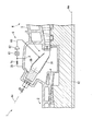
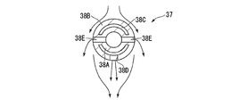
- FIG. 5 is a view taken along line VV in FIG. 4. It is sectional drawing which shows the modification of the peg which concerns on 1st embodiment of this invention.
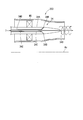
- FIG. 7 is a view taken along line VII-VII in FIG. 6. It is a principal part enlarged view of the combustor (1st nozzle) which concerns on 2nd embodiment of this invention.
- FIG. 11 is a view taken along line IX-IX in FIG. 10. It is a principal part enlarged view of the combustor (2nd nozzle) which concerns on 3rd embodiment of this invention.
- a gas turbine 1 includes a compressor 2, a combustor 3, a turbine 4, a casing 5, a combustor cooling system 6, and a combustor air introduction system 7. It is equipped with.
- Compressor 2 compresses external air to generate high-pressure compressed air. More specifically, the compressor 2 includes a compressor rotor 8 that rotates around the main axis Am, and a compressor casing 9 that covers the compressor rotor 8 from the outer peripheral side.
- the turbine 4 includes a turbine rotor 10 that rotates about the main axis Am, and a turbine casing 11 that covers the turbine rotor 10 from the outer peripheral side.
- the compressor rotor 8 and the turbine rotor 10 are integrally connected on the main axis Am to form a gas turbine rotor 12. Further, the compressor casing 9 and the turbine casing 11 are connected to each other to form a gas turbine casing 5 (hereinafter sometimes simply referred to as a casing 5).
- a generator 13 is connected to one end of the gas turbine rotor 12.
- the generator 13 is driven by the rotation of the gas turbine rotor 12 to extract electric power to the outside.
- the combustor 3 generates high-temperature and high-pressure combustion gas by burning fuel in the compressed air generated by the compressor 2 described above.
- the combustor 3 has a combustion cylinder 30 (cylinder) through which combustion gas passes.
- the combustion cylinder 30 of this embodiment has a double tube structure.
- a space between the inner peripheral side tube and the outer peripheral side tube of the combustion cylinder 30 is a cooling passage 31.
- air supplied through a combustor cooling system 6 described later flows. Thereby, the combustion cylinder 30 exposed to the high temperature of combustion gas can be protected from heat.
- the combustor cooling system 6 includes a first line 60 that connects the space in the casing 5 and the cooling passage 31 of the combustion cylinder 30, a heat exchanger 61 provided on the first line 60, and a sub And a compressor 62.
- One end of the first line 60 communicates with the interior of the passenger compartment 5 to extract a part of the compressed air flowing through the passenger compartment 5.
- the heat exchanger 61 exchanges heat between the extracted compressed air and external air.
- the air heat-exchanged by the heat exchanger 61 is pressurized by the sub compressor 62 and becomes cooling air.
- the sub compressor 62 is provided separately from the compressor 2 and can be operated independently of the compressor 2.
- the combustor air introduction system 7 is provided on the second line 70, which connects the extraction position P upstream of the heat exchanger 61 on the first line 60 and the inside of the combustor 3.
- the flow rate adjusting valve 71 is provided.
- the air flowing through the second line 70 is supplied separately from the fuel to the peg 38, the first nozzle 34, and the second nozzle 35, all of which will be described later, in the combustor 3.
- the combustor 3 includes a combustion cylinder 30, a swirler support cylinder 32, an outer cylinder 33, a first nozzle 34 and a second nozzle 35.
- the combustion cylinder 30 is formed in a cylindrical shape extending along the central axis Ac.
- the swirler support cylinder 32 is attached to one end side of the combustion cylinder 30.
- the outer cylinder 33 is attached to one end side of the swirler support cylinder 32.
- the first nozzle 34 and the second nozzle 35 are supported in the combustion cylinder 30 by the outer cylinder 33.
- the side where the outer cylinder 33 is located with respect to the swirler support cylinder 32 is referred to as the upstream side.
- the side where the combustion cylinder 30 is located with respect to the swirler support cylinder 32 is referred to as the downstream side.
- the swirler support cylinder 32 has a smaller outer diameter than the combustion cylinder 30. A portion including the other end portion of the swirler support cylinder 32 is inserted into the inner peripheral side of the combustion cylinder 30.
- the combustion cylinder 30 is fixed to the swirler support cylinder 32 through a connecting member 36 so as not to fall off.
- the outer cylinder 33 is a bottomed cylindrical member provided so as to close the combustor insertion hole 50 formed in the casing 5.
- the outer cylinder 33 includes a nozzle base 33A that supports the second nozzle 35 and the first nozzle 34, and an outer cylinder main body 33B that fixes and supports the nozzle base 33A with respect to the vehicle compartment 5.
- the nozzle base 33A is a member formed in a substantially disc shape with the central axis Ac as a center, and one second nozzle 35 is inserted into a region including the center point. Further, on the outer peripheral side of the second nozzle 35, a plurality of first nozzles 34 are arranged at intervals in the circumferential direction of the central axis line Ac. Both the first nozzle 34 and the second nozzle 35 are substantially tubular. The fuel supplied from the fuel supply source circulates inside the first nozzle 34 and the second nozzle 35.
- a fitting convex portion 33C that fits with the inner wall of the passenger compartment 5 is provided on the downstream surface of the outer cylinder main body 33B.
- the fitting protrusion 33C protrudes from the bottom of the outer cylinder main body 33B toward the downstream side.
- the inner peripheral surface of the fitting convex portion 33C is opposed to the outer peripheral surface of the swirler support cylinder 32 with a gap.
- This gap is an air flow path FC for guiding the compressed air in the passenger compartment 5 into the combustor 3.
- the part which connects the inner peripheral surface and bottom part of the fitting convex part 33C has comprised the curved shape.
- a gap is formed between the upstream end of the swirler support cylinder 32 and the bottom of the outer cylinder main body 33B. Thereby, the compressed air led from the downstream side to the upstream side along the air flow path FC is introduced into the inside of the swirler support cylinder 32.
- a peg 37 for supplying fuel into the air flow path FC is attached to the inner peripheral surface of the outer cylinder main body 33B.
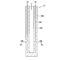
- the peg 37 is a rod-like nozzle provided so as to protrude from the inner peripheral surface of the outer cylinder main body 33B. More specifically, as shown in FIGS. 4 and 5, the peg 37 has a double tube structure.
- the peg 37 has a peg inner pipe 38A through which the fuel F flows, and a peg outer pipe 38B provided on the outer peripheral side of the peg inner pipe 38A.
- a gap that extends in the radial direction of these pipes is formed.
- the peg air flow path 38C communicates with the second line 70 in the above-described combustor air introduction system 7.
- the compressed air that circulates in the second line 70 circulates in the peg air flow path 38C.
- a peg air hole 38D for injecting the air in the peg air flow path 38C toward the outside is formed.
- a plurality of (two) injection holes 38E for injecting fuel are formed on the outer peripheral surface of the peg outer pipe 38B so as to communicate the inside and outside of the peg inner pipe 38A.
- these two injection holes 38E are opened in a direction orthogonal to the direction in which the peg inner tube 38A extends. Further, the two injection holes 38E are opened in a direction away from each other in the diameter direction of the peg outer tube 38B.
- the peg 37 thus configured is fixed to the outer cylinder main body 33B in the following posture. That is, as shown in FIG. 5, the two injection holes 38E are opened toward the direction intersecting (orthogonal) with the flow direction of the compressed air in the air flow path FC. The peg air hole 38D is opened toward the direction in which the compressed air flows away.
- the compressor 2 is driven by a power source (not shown).
- High-pressure compressed air is generated by driving the compressor 2.
- the compressed air is introduced into the combustor 3 through the space in the passenger compartment 5.
- a combustion flame is formed through ignition by an igniter (not shown).
- high-temperature and high-pressure combustion gas is generated.
- the combustion gas is further introduced into the subsequent turbine 4 through the space in the passenger compartment 5 to drive the turbine 4 to rotate.
- an external device such as the generator 13 connected to the shaft end of the turbine rotor 10 is driven.
- the temperature of the combustion gas generally reaches around 1500 ° C.
- measures for protecting each member of the combustor 3 from radiant heat or the like are necessary. Therefore, in the gas turbine 1 according to the present embodiment, a part of the combustor 3 is cooled by the combustor cooling system 6 described above. More specifically, after a portion of the compressed air in the passenger compartment 5 is extracted through the first line 60, the combustion cylinder 30 is cooled through heat exchange by the heat exchanger 61 and compression by the sub compressor 62. The extracted compressed air is supplied into the passage 31. Thereby, the combustion cylinder 30 can be sufficiently protected from the radiant heat and the like.
- a peg air hole 38D that opens toward the downstream side of the peg outer tube 38B is formed.
- the compressed air in the passenger compartment 5 is injected from the peg air hole 38 ⁇ / b> D through the combustor air introduction system 7.
- air and fuel staying on the downstream side of the peg outer pipe 38B can be pushed toward the downstream side. That is, the possibility of flashback around the peg 37 is sufficiently reduced, so that the gas turbine 1 can be stably operated even in a high temperature environment.
- the first embodiment of the present invention has been described above, but various modifications can be made to the above configuration without departing from the gist of the present invention.
- it was set as the structure which injects a fuel and air independently by making the peg 37 into a double pipe structure.
- the form of the peg 37 is not limited to this, and the configuration shown in FIGS. 6 and 7 can be adopted.
- the peg 37 (peg outer tube 38B) in the present modification is spaced inside the fuel flow path 34C through which fuel flows, and in the diameter direction of the peg 37 with respect to the fuel flow path 34C.
- an air flow path FC provided as described above.
- the fuel supplied from the fuel flow path 34C is injected outside through the injection hole 38E. From the air flow path FC, air is injected outside through the peg air hole 38D.
- the peg 37 can be integrally formed by one member in addition to obtaining the same operational effects as those of the first embodiment. For this reason, it is possible to reduce the number of parts and improve the maintainability associated therewith.
- the first nozzle 34 includes a cylindrical first nozzle body 34A through which fuel and compressed air circulate, and a first swirler provided upstream of the first nozzle body 34A.
- the first nozzle body 34A extends from the upstream side toward the downstream side, and the end portion on the downstream side is formed in a pointed shape that gradually decreases in diameter from the upstream side toward the downstream side.
- a plurality of first nozzle injection holes 34B for injecting fuel are formed in a portion slightly upstream from the downstream end of the first nozzle body 34A.
- the first nozzle injection holes 34B are arranged at equal intervals in the circumferential direction of the first nozzle body 34A.
- a fuel flow path 34C for circulating fuel is formed inside the first nozzle body 34A.
- the fuel flow path 34C extends in a straight line parallel to the central axis Ac.
- the first nozzle injection hole 34B forms a certain angle with respect to the fuel flow path 34C.
- a first nozzle air hole 34D for injecting compressed air is formed at the downstream end (tip) of the first nozzle body 34A.
- the first nozzle air hole 34D communicates with a first nozzle air flow path 34E formed inside the first nozzle body 34A.
- the combustor air introduction system 7 described above is connected to the upstream side of the first nozzle air flow path 34E. That is, air circulated from the combustor air introduction system 7 is injected from the first nozzle air hole 34D.
- the first swirler MS is provided on the outer peripheral surface of the first nozzle main body 34A and on the upstream side of the first nozzle injection hole 34B.
- the first swirler MS has a plurality of swirler vanes arranged at equal intervals in the circumferential direction of the first nozzle body 34A. Each swirler vane forms a certain angle with respect to the extending direction of the first nozzle body 34A when viewed from the radial direction of the first nozzle body 34A.
- a swirl component swirl flow component
- the flow in which the swirl is generated by the first swirler MS flows from the upstream side toward the downstream side while turning in the circumferential direction of the first nozzle 34.
- the compressed air in the passenger compartment 5 supplied from the upstream side of the first nozzle 34 flows through the space on the outer peripheral side of the first nozzle 34.
- the flow of the compressed air contains the swirl component.
- the fuel injected from the first nozzle injection hole 34B is mixed with the flow of compressed air containing the swirl component in a further downstream region, and a premixed gas is generated.
- the flame formed by the second nozzle 35 described above propagates to the premixed gas.
- the premixed gas is ignited to form a premixed combustion flame extending from the upstream side toward the downstream side in the combustion cylinder 30, and a high-temperature and high-pressure combustion gas is generated.
- the premixed combustion flame and the combustion gas also form a flow swirling in the circumferential direction of the first nozzle 34. For this reason, a swirl vortex center is formed on the extension line of the tip of the first nozzle 34. If the above premixed gas is trapped and stays in such a vortex center, the downstream flame may propagate and cause flashback.
- the first nozzle air hole 34D is formed at the tip of the first nozzle body 34A as described above. Therefore, compressed air can be ejected from the first nozzle air hole 34D toward the vortex center. Thereby, the flow velocity component from the upstream side to the downstream side in the vortex center can be increased. Therefore, the possibility that the premixed gas stays at the vortex center can be reduced. At the same time, the fuel concentration at the vortex center can be lowered by the supplied compressed air. Therefore, according to the combustor 203 according to this embodiment, the possibility of flashback around the first nozzle 34 can be sufficiently reduced.
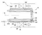
- the second nozzle 35 has a double tube structure.
- the second nozzle 35 has a second nozzle inner tube 35A and a second nozzle outer tube 35B.
- the second nozzle inner tube 35A extends along the central axis Ac.
- the second nozzle inner pipe 35A is formed with a fuel flow path 334C through which fuel flows.
- the second nozzle outer tube 35B is provided coaxially with the second nozzle inner tube 35A.
- the second nozzle outer tube 35B covers the second nozzle inner tube 35A from the outside.
- the second nozzle inner tube 35A has a cylindrical shape.
- a plurality of second nozzle injection holes 35C opening toward the downstream side are formed on the downstream end face of the second nozzle inner pipe 35A. More specifically, as shown in FIG. 10, a plurality of these second nozzle injection holes 35C are arranged at equal intervals in the circumferential direction of the central axis Ac. In the present embodiment, eight second nozzle injection holes 35C are formed.
- a partition wall 35D having a cylindrical shape centering on the central axis Ac is provided inside the second nozzle inner pipe 35A and on the inner peripheral side of the second nozzle injection hole 35C.
- a space extending in the radial direction of the central axis Ac is formed between the partition wall 35D and the inner peripheral surface of the second nozzle inner tube 35A. This space is a fuel flow path 334C through which fuel flows.
- the second nozzle outer tube 35B is provided so as to cover the second nozzle inner tube 35A from the outer peripheral side and the downstream side of the central axis Ac.
- a plurality of spacers 35E are provided between the second nozzle outer tube 35B and the second nozzle inner tube 35A. By this spacer 35E, a space is formed between the second nozzle inner tube 35A and the second nozzle outer tube 35B. This space is communicated with the above-described combustor air introduction system 7, thereby forming a second nozzle air flow path 35F through which compressed air flows.
- a flow rate adjustment valve 71 for adjusting the air flow rate in the flow path is provided on the second nozzle air flow path 35F.
- a plurality of (eight) second nozzle air holes 35G are formed in the downstream end face of the second nozzle outer pipe 35B and are opened at the same circumferential position as the second nozzle injection hole 35C. .
- Each second nozzle air hole 35G has a larger opening diameter than the second nozzle injection hole 35C. That is, as shown in FIG. 10, when viewed from the direction of the central axis Ac, the outer peripheral side of the second nozzle injection hole 35C is surrounded by the opening edge of the second nozzle air hole 35G.
- the second nozzle injection hole 35C and the second nozzle air hole 35G are both opened in a direction slightly inclined with respect to the central axis Ac. Specifically, the second nozzle injection hole 35C and the second nozzle air hole 35G are opened so as to go radially outward from the upstream side toward the downstream side. Further, in the present embodiment, the downstream end portion of the second nozzle injection hole 35C slightly protrudes from the downstream end surface of the second nozzle inner pipe 35A toward the downstream side.
- the second swirler PS is provided on the outer peripheral surface of the second nozzle outer tube 35B, similarly to the first swirler MS in the second embodiment.
- the second swirler PS has a plurality of swirler vanes arranged at intervals in the circumferential direction of the central axis Ac. By this second swirler PS, a swirl component is added to the compressed air flowing from the upstream side along the outer peripheral surface of the second nozzle 35.
- the operation of the combustor 303 will be described.
- the compressed air supplied from the inside of the passenger compartment 5 flows along the outer peripheral surface of the second nozzle 35 from the upstream side toward the downstream side.
- the fuel supplied through the fuel flow path 334C is injected downstream through the second nozzle injection hole 35C.
- This fuel is ignited by an ignition device (not shown) to generate a diffusion combustion flame (pilot flame).
- the pilot flame propagates to the premixed gas supplied from the first nozzle 34, whereby the premixed combustion flame is formed, and high-temperature and high-pressure combustion gas is generated.
- compressed air is supplied through the second nozzle air hole 35G into the flow of fuel injected from the second nozzle injection hole 35C. That is, gas in a state where compressed air and fuel are premixed can be injected from the second nozzle 35. Moreover, the flow rate of the compressed air is adjusted by providing the flow rate adjustment valve 71 on the extension of the second nozzle air flow path 35F.
- the flow rate of the compressed air is set to zero so that the pilot The flame can be a diffusion combustion flame.
- premixing from the second nozzle 35 is performed by supplying compressed air from the second nozzle air hole 35G. Gas can be blown out. That is, in addition to the first nozzle 34, the second nozzle 35 can realize combustion conditions equivalent to premixed combustion. Thus, the characteristics of the flame formed by the second nozzle 35 can be adjusted according to the operating state of the gas turbine 1. Therefore, the gas turbine 1 can be operated more stably and efficiently.
- the flow velocity of the fluid in the vicinity of the second nozzle 35 is increased by the compressed air injected from the second nozzle air hole 35G as described above. As a result, it is possible to sufficiently reduce the possibility that high-concentration fuel stays in the region or that the staying fuel component ignites to cause flashback.
- the relative positional relationship between the second nozzle 35 and the first nozzle 34 is not limited depending on the above-described embodiment, and other modes can be adopted depending on the design and specifications.
- the combustor 3, the combustor 203, and the combustor 303 are not necessarily limited to those provided in the gas turbine 1, and can be applied to any mechanical device that generally requires combustion. It is.
- the example which extracted the compressed air from the extraction position P of the compartment 5 side rather than the heat exchanger 61 in the combustor cooling system 6 was demonstrated.
- the extraction position P is closer to the cooling passage 31 than the heat exchanger 61. That is, the air compressed by the sub compressor 62 can be guided to the combustor air introduction system 7. Thereby, air can be stably introduced also into a relatively high pressure portion in the combustor 3.
- the gas turbine can provide a gas turbine that can be stably operated even at high temperatures.
Landscapes
- Engineering & Computer Science (AREA)
- Chemical & Material Sciences (AREA)
- Combustion & Propulsion (AREA)
- Mechanical Engineering (AREA)
- General Engineering & Computer Science (AREA)
Abstract
Description
本願は、2016年3月30日に出願された特願2016-068018号について優先権を主張し、その内容をここに援用する。
このようなガスタービンに用いられる燃焼器の一例として、下記特許文献1に記載されたものが知られている。特許文献1に係る燃焼器は、燃焼ガスが流通する燃焼筒と、燃焼筒内で火炎を形成する複数のノズルと、を主に備えている。ノズルによって形成された火炎によって燃焼筒内で高温高圧の燃焼ガスが生じる。
近年では、ガスタービンの性能向上に伴って運転温度が従前に比べて上昇する傾向にあることから、上記のフラッシュバックがさらに生じやすくなっている。また、ガスタービンの運転温度の上昇に伴って、NOxの発生量が増大してしまう可能性がある。
このため、高温の運転条件化でも、フラッシュバックの発生を十分に抑制することができるとともに、NOx発生量が低減されたガスタービンに対する要請が高まっている。
本発明の第一実施形態について、図1から図7を参照して説明する。図1に示すように、本実施形態に係るガスタービン1は、圧縮機2と、燃焼器3と、タービン4と、車室5と、燃焼器冷却系統6と、燃焼器空気導入系統7と、を備えている。
例えば、上記実施形態では、ペグ37を二重管構造とすることで、燃料と空気とを独立して噴射する構成とした。しかしながら、ペグ37の態様はこれに限定されず、図6と図7とに示す構成を採ることも可能である。
次に、本発明の第二実施形態について図8を参照して説明する。本実施形態は、以下の点で上記第一実施形態と異なっている。すなわち、本実施形態に係る燃焼器203では、第一ノズル34に対して燃焼器空気導入系統7から空気が供給される。
次に、本発明の第三実施形態について図9、図10を参照して説明する。本実施形態に係る燃焼器303では、第二ノズル35に対して、燃焼器空気導入系統7から圧縮空気が供給される。
2 圧縮機
3 燃焼器
4 タービン
5 車室
6 燃焼器冷却系統
7 燃焼器空気導入系統
8 圧縮機ロータ
9 圧縮機車室
10 タービンロータ
11 タービン車室
12 ガスタービンロータ
13 ジェネレータ
30 燃焼筒
31 冷却通路
32 スワラ支持筒
33 外筒
34 第一ノズル
35 第二ノズル
36 接続部材
37 ペグ
50 燃焼器挿通孔
60 第一ライン
61 熱交換器
62 サブ圧縮機
70 第二ライン
71 流量調整弁
203 燃焼器
303 燃焼器
334C 燃料流路
33A ノズル台
33B 外筒本体
33C 嵌合凸部
34A 第一ノズル本体
34B 第一ノズル噴射孔
34C 燃料流路
34D 第一ノズル空気孔
34E 第一ノズル空気流路
35A 第二ノズル内側管
35B 第二ノズル外側管
35C 第二ノズル噴射孔
35D 隔壁
35E スペーサ
35F 第二ノズル空気流路
35G 第二ノズル空気孔
PS 第二スワラ
38A ペグ内管
38Bペグ外管
38C ペグ空気流路
38D ペグ空気孔
38E 噴射孔
Ac 中心軸線
Am 主軸線
FC 空気流路
MS 第一スワラ
P 抽気位置
Claims (6)
- 外部空気を圧縮して圧縮空気を生成する圧縮機と、
前記圧縮空気が導入される車室と、
前記車室内から導入された前記圧縮空気を燃料とともに混合して燃焼させて、燃焼ガスを生成するとともに、該燃焼ガスが内側を通過する筒体を有する燃焼器と、
前記燃焼ガスによって駆動されるタービンと、
前記圧縮機に対して独立に運転可能なサブ圧縮機と、前記車室内の空気を抽気して、前記サブ圧縮機で昇圧した後に熱交換する熱交換器とを有し、熱交換された空気を前記筒体の冷却通路に導入する燃焼器冷却系統と、
前記燃焼器冷却系統を流通する空気を抽気して、前記燃焼器内に導入する燃焼器空気導入系統と、
を備えるガスタービン。 - 前記燃焼器空気導入系統は、前記燃焼器冷却系統における前記熱交換器よりも前記車室側の抽気位置から抽気した空気を前記燃焼器内に導入する請求項1に記載のガスタービン。
- 前記燃焼器空気導入系統は、前記燃焼器冷却系統における前記熱交換器よりも前記冷却通路側の抽気位置から抽気した空気を前記燃焼器内に導入する請求項1に記載のガスタービン。
- 前記燃焼器は、
前記筒体の外周側に設けられて、該筒体の外周面との間に前記圧縮空気が流通する空気流路を形成する外筒と、
前記空気流路中で、前記圧縮空気の流通方向と交差する方向に前記燃料を噴射する噴射孔が形成されたペグと、
を有し、
前記ペグには、前記燃焼器空気導入系統から供給された空気を前記圧縮空気の流通方向下流側に向かって噴射するペグ空気孔が形成されている請求項1から3のいずれか一項に記載のガスタービン。 - 前記燃焼器は、
前記筒体内に前記燃料を供給し、前記圧縮空気と混合して燃焼させる第一ノズルと、
前記第一ノズルの外周側に設けられ、前記燃焼ガスにスワールを生じさせる第一スワラと、
を有し、
前記第一ノズルの先端には、前記スワールの渦中心に向かって前記燃焼器空気導入系統から供給された空気を噴射する第一ノズル空気孔が形成されている請求項1から4のいずれか一項に記載のガスタービン。 - 前記燃焼器は、
前記第一ノズルと平行に設けられて、該第一ノズルに着火するための燃料を噴射する第二ノズル噴射孔が形成された第二ノズルを有し、
前記第二ノズルには、前記第二ノズル噴射孔を外周側から囲むように形成され、前記燃焼器空気導入系統から供給された空気を噴射する第二ノズル空気孔が形成されている請求項5に記載のガスタービン。
Priority Applications (5)
| Application Number | Priority Date | Filing Date | Title |
|---|---|---|---|
| DE112017001613.4T DE112017001613B4 (de) | 2016-03-30 | 2017-03-28 | Gasturbine |
| CN201780020646.8A CN108884762B (zh) | 2016-03-30 | 2017-03-28 | 燃气轮机 |
| KR1020187027927A KR20180114204A (ko) | 2016-03-30 | 2017-03-28 | 가스 터빈 |
| KR1020217011349A KR102386375B1 (ko) | 2016-03-30 | 2017-03-28 | 가스 터빈 |
| US16/089,076 US11118512B2 (en) | 2016-03-30 | 2017-03-28 | Gas turbine |
Applications Claiming Priority (2)
| Application Number | Priority Date | Filing Date | Title |
|---|---|---|---|
| JP2016-068018 | 2016-03-30 | ||
| JP2016068018A JP6754595B2 (ja) | 2016-03-30 | 2016-03-30 | ガスタービン |
Publications (1)
| Publication Number | Publication Date |
|---|---|
| WO2017170477A1 true WO2017170477A1 (ja) | 2017-10-05 |
Family
ID=59965792
Family Applications (1)
| Application Number | Title | Priority Date | Filing Date |
|---|---|---|---|
| PCT/JP2017/012522 Ceased WO2017170477A1 (ja) | 2016-03-30 | 2017-03-28 | ガスタービン |
Country Status (6)
| Country | Link |
|---|---|
| US (1) | US11118512B2 (ja) |
| JP (1) | JP6754595B2 (ja) |
| KR (2) | KR20180114204A (ja) |
| CN (1) | CN108884762B (ja) |
| DE (1) | DE112017001613B4 (ja) |
| WO (1) | WO2017170477A1 (ja) |
Cited By (1)
| Publication number | Priority date | Publication date | Assignee | Title |
|---|---|---|---|---|
| RU2727946C1 (ru) * | 2019-02-27 | 2020-07-27 | Мицубиси Хитачи Пауэр Системз, Лтд. | Камера сгорания газовой турбины и газовая турбина |
Families Citing this family (9)
| Publication number | Priority date | Publication date | Assignee | Title |
|---|---|---|---|---|
| JP6895867B2 (ja) | 2017-10-27 | 2021-06-30 | 三菱パワー株式会社 | ガスタービン燃焼器、ガスタービン |
| JP7305761B2 (ja) | 2019-05-24 | 2023-07-10 | 三菱パワー株式会社 | 尾筒、燃焼器、ガスタービン、及びガスタービン設備 |
| JP7349266B2 (ja) * | 2019-05-31 | 2023-09-22 | 三菱重工業株式会社 | ガスタービンおよびその制御方法並びにコンバインドサイクルプラント |
| JP7393262B2 (ja) * | 2020-03-23 | 2023-12-06 | 三菱重工業株式会社 | 燃焼器、及びこれを備えるガスタービン |
| DE112021002636B4 (de) | 2020-06-26 | 2025-12-04 | Mitsubishi Heavy Industries, Ltd. | Brennstoffeinspritzdüse, brennkammer mit der brennstoffeinspritzdüse, und gasturbine mit der brennkammer |
| US12405007B2 (en) | 2021-12-03 | 2025-09-02 | General Electric Company | Combustor size rating for a gas turbine engine using hydrogen fuel |
| US11815269B2 (en) | 2021-12-29 | 2023-11-14 | General Electric Company | Fuel-air mixing assembly in a turbine engine |
| US20260168674A1 (en) * | 2024-12-12 | 2026-06-18 | General Electric Company | Gas turbine engine including hydrogen-compatible fuel-air mixer with multi-jet mixing tube |
| US12655977B1 (en) * | 2024-12-12 | 2026-06-16 | General Electric Company | Fuel injector architectures for turbine engines with multi-stage geometry, staged fuel injection, and hybrid swirl control |
Citations (7)
| Publication number | Priority date | Publication date | Assignee | Title |
|---|---|---|---|---|
| JPH01130015A (ja) * | 1987-10-13 | 1989-05-23 | Westinghouse Electric Corp <We> | ガスタービンエンジン用燃料ノズル組立体 |
| JPH03105104A (ja) * | 1989-09-20 | 1991-05-01 | Hitachi Ltd | ガスタービン燃料噴霧装置 |
| JP2003042453A (ja) * | 2001-07-26 | 2003-02-13 | Mitsubishi Heavy Ind Ltd | ガスタービンの予混合ノズルまたは予混合燃焼器 |
| JP2008025910A (ja) * | 2006-07-20 | 2008-02-07 | Mitsubishi Heavy Ind Ltd | ガスタービン燃焼器 |
| JP2008082247A (ja) * | 2006-09-27 | 2008-04-10 | Mitsubishi Heavy Ind Ltd | ガスタービン |
| JP2013178035A (ja) * | 2012-02-28 | 2013-09-09 | Mitsubishi Heavy Ind Ltd | パイロットノズル、これを備えたガスタービン燃焼器およびガスタービン |
| JP2015222022A (ja) * | 2014-05-22 | 2015-12-10 | 三菱日立パワーシステムズ株式会社 | 冷却装置、これを備えているガスタービン設備、冷却装置の運転方法 |
Family Cites Families (16)
| Publication number | Priority date | Publication date | Assignee | Title |
|---|---|---|---|---|
| JP2713627B2 (ja) | 1989-03-20 | 1998-02-16 | 株式会社日立製作所 | ガスタービン燃焼器、これを備えているガスタービン設備、及びこの燃焼方法 |
| JP2951620B2 (ja) | 1989-03-20 | 1999-09-20 | 株式会社日立製作所 | ガスタービン燃焼器 |
| US5165241A (en) * | 1991-02-22 | 1992-11-24 | General Electric Company | Air fuel mixer for gas turbine combustor |
| US5253478A (en) * | 1991-12-30 | 1993-10-19 | General Electric Company | Flame holding diverging centerbody cup construction for a dry low NOx combustor |
| JPH05203146A (ja) | 1992-01-29 | 1993-08-10 | Hitachi Ltd | ガスタービン燃焼器及びガスタービン発電装置 |
| DE4210544A1 (de) * | 1992-03-31 | 1993-10-07 | Asea Brown Boveri | Gasturbinenanlage |
| JP3183053B2 (ja) * | 1994-07-20 | 2001-07-03 | 株式会社日立製作所 | ガスタービン燃焼器及びガスタービン |
| JPH0886407A (ja) | 1994-09-19 | 1996-04-02 | Hitachi Ltd | ガスタービン燃焼器 |
| US5657632A (en) * | 1994-11-10 | 1997-08-19 | Westinghouse Electric Corporation | Dual fuel gas turbine combustor |
| US5782076A (en) * | 1996-05-17 | 1998-07-21 | Westinghouse Electric Corporation | Closed loop air cooling system for combustion turbines |
| JP3619626B2 (ja) * | 1996-11-29 | 2005-02-09 | 株式会社東芝 | ガスタービン燃焼器の運転方法 |
| JPH11343869A (ja) | 1998-06-02 | 1999-12-14 | Hitachi Ltd | ガスタービン燃焼器およびその制御方法 |
| JP2013139975A (ja) | 2012-01-06 | 2013-07-18 | Hitachi Ltd | ガスタービン燃焼器 |
| US9441835B2 (en) * | 2012-10-08 | 2016-09-13 | General Electric Company | System and method for fuel and steam injection within a combustor |
| JP3183053U (ja) | 2013-01-23 | 2013-04-25 | 上美商標工業股▲ふん▼有限公司 | 靴の靴面構造 |
| JP6406959B2 (ja) | 2014-09-30 | 2018-10-17 | デクセリアルズ株式会社 | 小型反応器、及び反応装置 |
-
2016
- 2016-03-30 JP JP2016068018A patent/JP6754595B2/ja active Active
-
2017
- 2017-03-28 CN CN201780020646.8A patent/CN108884762B/zh active Active
- 2017-03-28 KR KR1020187027927A patent/KR20180114204A/ko not_active Ceased
- 2017-03-28 KR KR1020217011349A patent/KR102386375B1/ko active Active
- 2017-03-28 DE DE112017001613.4T patent/DE112017001613B4/de active Active
- 2017-03-28 WO PCT/JP2017/012522 patent/WO2017170477A1/ja not_active Ceased
- 2017-03-28 US US16/089,076 patent/US11118512B2/en active Active
Patent Citations (7)
| Publication number | Priority date | Publication date | Assignee | Title |
|---|---|---|---|---|
| JPH01130015A (ja) * | 1987-10-13 | 1989-05-23 | Westinghouse Electric Corp <We> | ガスタービンエンジン用燃料ノズル組立体 |
| JPH03105104A (ja) * | 1989-09-20 | 1991-05-01 | Hitachi Ltd | ガスタービン燃料噴霧装置 |
| JP2003042453A (ja) * | 2001-07-26 | 2003-02-13 | Mitsubishi Heavy Ind Ltd | ガスタービンの予混合ノズルまたは予混合燃焼器 |
| JP2008025910A (ja) * | 2006-07-20 | 2008-02-07 | Mitsubishi Heavy Ind Ltd | ガスタービン燃焼器 |
| JP2008082247A (ja) * | 2006-09-27 | 2008-04-10 | Mitsubishi Heavy Ind Ltd | ガスタービン |
| JP2013178035A (ja) * | 2012-02-28 | 2013-09-09 | Mitsubishi Heavy Ind Ltd | パイロットノズル、これを備えたガスタービン燃焼器およびガスタービン |
| JP2015222022A (ja) * | 2014-05-22 | 2015-12-10 | 三菱日立パワーシステムズ株式会社 | 冷却装置、これを備えているガスタービン設備、冷却装置の運転方法 |
Cited By (1)
| Publication number | Priority date | Publication date | Assignee | Title |
|---|---|---|---|---|
| RU2727946C1 (ru) * | 2019-02-27 | 2020-07-27 | Мицубиси Хитачи Пауэр Системз, Лтд. | Камера сгорания газовой турбины и газовая турбина |
Also Published As
| Publication number | Publication date |
|---|---|
| US20190107053A1 (en) | 2019-04-11 |
| JP6754595B2 (ja) | 2020-09-16 |
| CN108884762A (zh) | 2018-11-23 |
| JP2017180267A (ja) | 2017-10-05 |
| KR20180114204A (ko) | 2018-10-17 |
| KR102386375B1 (ko) | 2022-04-14 |
| DE112017001613T5 (de) | 2018-12-13 |
| US11118512B2 (en) | 2021-09-14 |
| KR20210045518A (ko) | 2021-04-26 |
| CN108884762B (zh) | 2023-10-03 |
| DE112017001613B4 (de) | 2022-12-22 |
Similar Documents
| Publication | Publication Date | Title |
|---|---|---|
| JP6754595B2 (ja) | ガスタービン | |
| CN103032892B (zh) | 燃烧器和用于将燃料供应到燃烧器的方法 | |
| JP6736284B2 (ja) | 予混合燃料ノズル組立体 | |
| US7886991B2 (en) | Premixed direct injection nozzle | |
| KR101864501B1 (ko) | 가스 터빈 연소기 | |
| US8984887B2 (en) | Combustor and method for supplying fuel to a combustor | |
| JP6134544B2 (ja) | 作動流体を燃焼器に供給するシステム | |
| EP2551598B1 (en) | Method of operating a turbomachine | |
| KR102228706B1 (ko) | 연소기용 노즐, 연소기 및 가스 터빈 | |
| WO2016056579A1 (ja) | 燃焼器及びガスタービンエンジン | |
| US20120282558A1 (en) | Combustor nozzle and method for supplying fuel to a combustor | |
| US10309655B2 (en) | Cooling system for fuel nozzles within combustor in a turbine engine | |
| EP3102877B1 (en) | Combustor | |
| JP2013140004A (ja) | 燃焼器燃料ノズル及び燃焼器への燃料供給方法 | |
| EP2515041B1 (en) | Fuel Nozzle And Method For Operating A Combustor | |
| CN106969379A (zh) | 预混燃料喷嘴组件筒 | |
| JP2016099107A (ja) | 予混合燃料ノズル組立体 | |
| EP2868972B1 (en) | Gas turbine combustor | |
| EP2383517A2 (en) | Fluid cooled injection nozzle assembly for a gas turbomachine | |
| EP3505826B1 (en) | Combustor for a gas turbine and gas turbine for power plant comprising such a combustor | |
| JP6326205B2 (ja) | 燃料ノズル、燃焼器、及びガスタービン |
Legal Events
| Date | Code | Title | Description |
|---|---|---|---|
| ENP | Entry into the national phase |
Ref document number: 20187027927 Country of ref document: KR Kind code of ref document: A |
|
| WWE | Wipo information: entry into national phase |
Ref document number: 201780020646.8 Country of ref document: CN |
|
| 121 | Ep: the epo has been informed by wipo that ep was designated in this application |
Ref document number: 17775014 Country of ref document: EP Kind code of ref document: A1 |
|
| 122 | Ep: pct application non-entry in european phase |
Ref document number: 17775014 Country of ref document: EP Kind code of ref document: A1 |