WO2017170258A1 - 液体吐出ヘッド及び液体の循環方法 - Google Patents
液体吐出ヘッド及び液体の循環方法 Download PDFInfo
- Publication number
- WO2017170258A1 WO2017170258A1 PCT/JP2017/012113 JP2017012113W WO2017170258A1 WO 2017170258 A1 WO2017170258 A1 WO 2017170258A1 JP 2017012113 W JP2017012113 W JP 2017012113W WO 2017170258 A1 WO2017170258 A1 WO 2017170258A1
- Authority
- WO
- WIPO (PCT)
- Prior art keywords
- liquid
- electrode
- discharge
- port
- substrate
- Prior art date
- Legal status (The legal status is an assumption and is not a legal conclusion. Google has not performed a legal analysis and makes no representation as to the accuracy of the status listed.)
- Ceased
Links
Images













Classifications
-
- B—PERFORMING OPERATIONS; TRANSPORTING
- B41—PRINTING; LINING MACHINES; TYPEWRITERS; STAMPS
- B41J—TYPEWRITERS; SELECTIVE PRINTING MECHANISMS, i.e. MECHANISMS PRINTING OTHERWISE THAN FROM A FORME; CORRECTION OF TYPOGRAPHICAL ERRORS
- B41J2/00—Typewriters or selective printing mechanisms characterised by the printing or marking process for which they are designed
- B41J2/005—Typewriters or selective printing mechanisms characterised by the printing or marking process for which they are designed characterised by bringing liquid or particles selectively into contact with a printing material
- B41J2/01—Ink jet
- B41J2/17—Ink jet characterised by ink handling
- B41J2/175—Ink supply systems ; Circuit parts therefor
-
- B—PERFORMING OPERATIONS; TRANSPORTING
- B41—PRINTING; LINING MACHINES; TYPEWRITERS; STAMPS
- B41J—TYPEWRITERS; SELECTIVE PRINTING MECHANISMS, i.e. MECHANISMS PRINTING OTHERWISE THAN FROM A FORME; CORRECTION OF TYPOGRAPHICAL ERRORS
- B41J2/00—Typewriters or selective printing mechanisms characterised by the printing or marking process for which they are designed
- B41J2/005—Typewriters or selective printing mechanisms characterised by the printing or marking process for which they are designed characterised by bringing liquid or particles selectively into contact with a printing material
- B41J2/01—Ink jet
- B41J2/135—Nozzles
- B41J2/14—Structure thereof only for on-demand ink jet heads
- B41J2/14016—Structure of bubble jet print heads
- B41J2/14032—Structure of the pressure chamber
- B41J2/1404—Geometrical characteristics
-
- B—PERFORMING OPERATIONS; TRANSPORTING
- B41—PRINTING; LINING MACHINES; TYPEWRITERS; STAMPS
- B41J—TYPEWRITERS; SELECTIVE PRINTING MECHANISMS, i.e. MECHANISMS PRINTING OTHERWISE THAN FROM A FORME; CORRECTION OF TYPOGRAPHICAL ERRORS
- B41J2/00—Typewriters or selective printing mechanisms characterised by the printing or marking process for which they are designed
- B41J2/005—Typewriters or selective printing mechanisms characterised by the printing or marking process for which they are designed characterised by bringing liquid or particles selectively into contact with a printing material
- B41J2/01—Ink jet
- B41J2/17—Ink jet characterised by ink handling
- B41J2/18—Ink recirculation systems
-
- B—PERFORMING OPERATIONS; TRANSPORTING
- B41—PRINTING; LINING MACHINES; TYPEWRITERS; STAMPS
- B41J—TYPEWRITERS; SELECTIVE PRINTING MECHANISMS, i.e. MECHANISMS PRINTING OTHERWISE THAN FROM A FORME; CORRECTION OF TYPOGRAPHICAL ERRORS
- B41J2202/00—Embodiments of or processes related to ink-jet or thermal heads
- B41J2202/01—Embodiments of or processes related to ink-jet heads
- B41J2202/12—Embodiments of or processes related to ink-jet heads with ink circulating through the whole print head
Definitions
- the present invention relates to a liquid discharge head and a liquid circulation method, and more particularly to a configuration for causing a liquid to flow in the vicinity of a discharge port.
- An object of the present invention is to provide a liquid discharge head capable of reducing the thickening of the liquid due to the evaporation of the liquid from the discharge port and capable of arranging the discharge ports at high density.
- the liquid ejection head of the present invention is provided with an ejection port array in which a plurality of ejection ports that eject liquid are arranged, a plurality of energy generation elements that generate energy for ejecting liquid, and a plurality of energy generation elements.
- a substrate and a plurality of through-holes penetrating the substrate are arranged between the through-hole row, the through-hole row, and the discharge-port row, and each discharge port of the discharge-port row and each through-hole of the through-hole row.
- a plurality of linear liquid channels connected to each other; and an electrode that is provided in each of the plurality of liquid channels and generates an electroosmotic flow in the liquid.
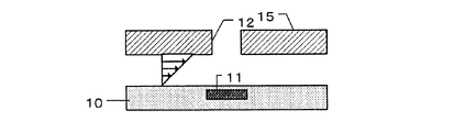
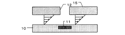
- FIG. 2 is a schematic diagram of a liquid ejection head according to the first embodiment of the present invention.
- FIG. 2 is a schematic diagram of a liquid ejection head according to the first embodiment of the present invention.
- FIG. 2 is a schematic diagram of a liquid ejection head according to the first embodiment of the present invention.
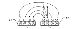
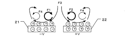
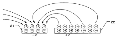
- FIG. 3 is a schematic diagram illustrating a flow velocity distribution in the liquid ejection head according to the first embodiment of the present invention. It is a schematic diagram explaining the generation mechanism of the driving force by an electroosmotic flow. It is a schematic diagram explaining the generation mechanism of the driving force by an electroosmotic flow. It is a schematic diagram explaining the generation mechanism of the driving force by an electroosmotic flow. It is a schematic diagram explaining the generation mechanism of the driving force by an electroosmotic flow.
- FIG. 10 is a schematic diagram of a flow velocity distribution in a liquid ejection head according to a fifth embodiment of the present invention.
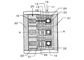
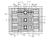
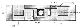
- FIG. 1A is a perspective view of a recording element substrate of a liquid discharge head according to the first embodiment of the present invention.
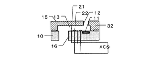
- 1B is a cross-sectional view of the recording element substrate shown in FIG. 1A
- FIG. 1C is a cross-sectional view taken along the line AA in FIG. 1B
- FIG. 1D is a schematic diagram showing a flow velocity distribution in the same cross section as FIG.
- the recording element substrate 1 has a substrate 10 and a discharge port forming member 15.
- the discharge port forming member 15 is bonded to the substrate 10.
- the substrate 10 includes an energy generating element 11 that generates energy for discharging ink.
- a plurality of discharge ports 12 are arranged in the discharge port forming member 15, and the plurality of discharge ports 12 are arranged in a line to form a discharge port array 19.
- the recording element substrate 1 of the present embodiment has two ejection port arrays 19, but the number of ejection port arrays 19 is not limited to this.
- the substrate 10 is formed with a plurality of first through holes 16 that penetrate the substrate 10 from the front surface to the back surface.
- a plurality of first liquid flow paths 13 are formed through which the first through holes 16 and the pressure chambers 20 communicate with each other.
- the first liquid channel 13 extends linearly.
- a plurality of pressure chambers 20 each having an energy generating element 11 therein are formed between the discharge port forming member 15 and the substrate 10 and on the downstream side of the first liquid flow path 13 with respect to the ink flow. .
- the pressure chamber 20 is a region sandwiched between the partition walls 32 and indicates a region where the energy generating element 11 is provided.
- the discharge port 12 faces the energy generating element 11 in a direction perpendicular to the surface of the substrate 10 facing the discharge port forming member 15.
- the pressure chamber 20 and the first through-hole 16 are provided for each corresponding liquid flow path or each discharge port 12. Accordingly, the first through port 16, the first liquid channel 13 and the pressure chamber 20 form an independent channel for each discharge port 12.
- the plurality of first through holes 16 form a first through hole array 25.
- the first through port array 25 extends along the discharge port array 19. Ink is supplied from the first through-hole 16 to the pressure chamber 20 through the first liquid flow path 13. The ink supplied to the pressure chamber 20 is heated by the energy generating element 11 and discharged from the discharge port 12 by the pressure of the generated bubbles.
- the first liquid channel 13 is provided with two types of electrodes. Hereinafter, these electrodes are referred to as a first electrode 21 and a second electrode 22. Both the first electrode 21 and the second electrode 22 are provided on the substrate 10.
- the first electrode 21 is connected to one end (+ terminal) of the AC power supply AC, and the second electrode 22 is connected to the other end ( ⁇ end) of the AC power supply AC.
- the first electrode 21 is smaller in dimension than the second electrode 22 in the ink flow direction, that is, the direction along the first liquid flow path 13.
- the dimensions of the first electrode 21 and the second electrode 22 in the direction perpendicular to the ink flow direction are approximately the same. Accordingly, the first electrode 21 has a smaller area facing the ink than the second electrode 22.
- a plurality of first electrodes 21 and second electrodes 22 are provided in the first liquid flow path 13 and are alternately provided.
- the first electrode 21 and the second electrode 22 are formed from the first through hole 16 toward the pressure chamber 20 in the first electrode 21, the second electrode 22, the first electrode 21, the second electrode 22. ⁇ It is provided in the order.
- the first liquid channel 13 and the second liquid channel 14 may be provided with at least one pair of the first electrode 21 and the second electrode 22 adjacent to each other.
- the plurality of first electrodes 21 are connected to a common first wiring 24, and the plurality of second electrodes 22 are connected to a common second wiring 23.
- the first wiring 24 and the second wiring 23 are provided in a lower region of the discharge port forming member 15 (a lower region of the partition wall 32).
- the first wiring 24 and the second wiring 23 are arranged on opposite sides of the first liquid flow path 13.
- the plurality of first electrodes 21 and the plurality of second electrodes 22 extend from the first wiring 24 and the second wiring 23 in a comb shape in opposite directions.
- the second wiring 23 extends along the first liquid flow path 13, further extends between the first through holes 16 adjacent to each other, and is viewed from the second electrode 22 at the tip of the first through hole 16.
- One common wiring 30 is connected.
- the first wiring 24 extends along the first liquid flow path 13, further extends between the energy generating elements 11 adjacent to each other, and is viewed from the first electrode 21, and is connected to the second common wiring at the tip of the energy generating element 11. 31 is connected. Thereby, the first wiring 24 and the second wiring 23 are prevented from being complicated, and an increase in the dimension of the element substrate 10 is suppressed.
- An AC voltage is applied to the first electrode 21 and the second electrode.
- a negative voltage ( ⁇ V) is applied to the first electrode 21 and a positive voltage (+ V) is applied to the second electrode.
- a positive voltage (+ V) is applied to the second electrode.
- a semicircular electric field E is formed in the ink from the second electrode 22 to the first electrode 21. This electric field is symmetrical with respect to a line intermediate between the first electrode 21 and the second electrode 22.
- An electric field component E1 parallel to the surfaces of the first and second electrodes 21 and 22 is generated on the surfaces of the first and second electrodes 21 and 22.
- This electric field component E1 exerts a Coulomb force on the charges induced on the first and second electrodes 21 and 22.
- the electric field component E1 is directed leftward in the figure at a position close to the gap between the electrodes. Since the positive charge receives a force in the same direction as the electric field, as shown in FIG.
- a rotating vortex F1 in which the ink in contact with the first electrode 21 flows leftward in the figure is generated. Since the negative charge receives a force in the direction opposite to the electric field, a rotating vortex F2 in which the ink in contact with the second electrode 22 flows rightward in the figure is generated. Since the ink flows away from the interelectrode gap, an ink flow F3 that replenishes the ink is generated in the interelectrode gap. In addition, since the direction of the electric field is reversed at the end of the electrode away from the inter-electrode gap, a rotating vortex F4 is generated in which the ink flows toward the inter-electrode gap. However, since the electric field is weak, the Coulomb force received by the ink is small.
- the dimension in the flow direction of the second electrode 22 is larger than the dimension in the flow direction of the first electrode 21.
- the electric field distribution differs between the first electrode 21 and the second electrode 22.
- a small rotating vortex F5 having a high flow velocity is formed in the vicinity of the first electrode 21.
- a small rotating vortex F7 having a low flow velocity is formed at a low potential portion, and a large rotating vortex F6 having a high flow velocity is formed at a high potential portion.
- ink is drawn from the first electrode 21 to the inter-electrode gap, and an ink flow in which the ink flows from the first electrode 21 toward the second electrode 22 is generated.
- Such electroosmotic flow generates a driving force for flowing ink from the first liquid flow path 13 toward the pressure chamber 20. That is, the ink passes through the first liquid channel 13 from the first through-hole 16 by the electroosmotic flow generated by the first electrode 21 and the second electrode 22 provided in the first liquid channel 13. Into the pressure chamber 20.
- the energy generating element 11 When the energy generating element 11 is operating, part of the ink that has flowed into the pressure chamber 20 is ejected from the ejection port 12. Even when the energy generating element 11 is not in operation, an electroosmotic flow is generated by the AC power source AC connected to the first electrode 21 and the second electrode 22, so that the first liquid flow path 13 and the pressure are The ink in the chamber 20 is agitated.
- the accumulation of the concentrated ink in the pressure chamber 20 can be suppressed. Therefore, it is possible to eject relatively fresh ink that is not thickened or has a small degree of thickening from the ejection port 12, and it is possible to reduce color unevenness of the image.
- the first wiring 24 connected to the first electrode 21 can be provided between the first through-holes 16, the first electrode 21 is provided between the first through-holes and the discharge ports 12.
- the first liquid channel 13 can be disposed. Therefore, the first and second electrodes 21 and 22 and the discharge ports 12 can be arranged with high density, and the size of the recording element substrate can be easily reduced.
- a plurality of through holes 16 for supplying ink are provided in the substrate 10, and the liquid channel (first liquid channel 13) that connects the through holes 16 and the pressure chambers 20 is the first.
- the first and second electrodes are provided to generate an electroosmotic flow.
- FIGS. 3A to 3C The configuration of the recording element substrate of the liquid discharge head according to the second embodiment of the present invention will be described with reference to FIGS. 3A to 3C.
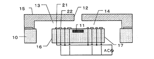
- the differences from the first embodiment will be mainly described, and therefore, the description of the first embodiment should be referred to for the parts that are not specifically described.
- 3A is a cross-sectional view of the recording element substrate of the liquid discharge head according to the second embodiment of the present invention
- FIG. 3B is a cross-sectional view taken along line AA in FIG. 3A
- FIG. 3C is a flow velocity in the same cross section as FIG. It is a schematic diagram which shows distribution.
- the second liquid flow path 14 is provided downstream of the pressure chamber 20 in the ink flow direction.
- the first electrode 21 and the second electrode 22 are not arranged in the second liquid channel 14.
- the substrate 10 is formed with a plurality of second through holes 17 that penetrate the substrate 10 from the front surface to the back surface.
- the pressure chamber 20 provided with the discharge port 12 is disposed between the first liquid channel 13 and the second liquid channel 14.
- the first through port 16, the first liquid channel 13, the pressure chamber 20, the second liquid channel 14, and the second through port 17 form an independent channel for each discharge port 12. ing.
- the ink that has not been ejected from the ejection port 12 flows through the second liquid flow path 14 to the second through-hole 17.
- the ink that has flowed out of the liquid discharge head flows again into the liquid discharge head after passing through the ink tank or the like of the recording apparatus.
- the ink in the pressure chamber 20 is circulated between the outside of the pressure chamber 20.
- the ink circulates inside the liquid discharge head (the ink flows between the inside and the outside of the pressure chamber 20). It can also be applied. With such a configuration, an ink flow that passes through the pressure chamber 20 is formed even when ink is not ejected, and retention of thickened ink at the ejection port 12 can be suppressed. Accordingly, it is possible to reduce the thickening of the ink and reduce the color unevenness of the image.
- FIGS. 4A to 4C The configuration of the recording element substrate of the liquid ejection head according to the third embodiment of the present invention will be described with reference to FIGS. 4A to 4C. In the following description, differences from the second embodiment will be mainly described, and therefore, the description of the second embodiment should be referred to for a part where a specific description is omitted.
- 4A is a cross-sectional view of the recording element substrate of the liquid discharge head according to the third embodiment of the present invention
- FIG. 4B is a cross-sectional view taken along line AA of FIG. 4A
- FIG. 4C is a flow velocity in the same cross section as FIG. It is a schematic diagram which shows distribution.
- the first electrode 21 and the second electrode 22 are disposed in the second liquid flow path 14.
- Other configurations are the same as those of the second embodiment. Since the first electrode 21 and the second electrode 22 are disposed in the first liquid channel 13 and the second liquid channel 14, respectively, the effect of discharging the ink concentrated inside the ejection port 12 is obtained. large. Therefore, it is difficult for the concentrated ink to stay inside the pressure chamber 20. Therefore, it is possible to further reduce the viscosity increase of the ink and reduce the color unevenness of the image.
- FIGS. 5A to 7C The configuration of the recording element substrate of the liquid ejection head according to the fourth embodiment of the present invention will be described with reference to FIGS. 5A to 7C. In the following description, differences from the first to third embodiments will be mainly described, and therefore, the description of the first to third embodiments should be referred to for portions where specific descriptions are omitted.
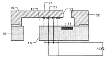
- 5A is a cross-sectional view of the recording element substrate of the liquid discharge head according to the fourth embodiment of the present invention
- FIG. 5B is a cross-sectional view taken along line AA of FIG. 5A
- FIG. 5C is a flow velocity in the same cross section as FIG. It is a schematic diagram which shows distribution.
- the first electrode 21 and the second electrode 22 are disposed on the back surface of the discharge port forming member 15.
- the back surface means the surface of the discharge port forming member 15 that faces the pressure chamber 20. Therefore, filling of the electric double layer occurs on the electrode on the back surface of the discharge port forming member 15. Therefore, as shown in FIG. 5C, a flow velocity distribution is obtained in which the flow velocity is large on the back surface of the discharge port forming member 15 and gradually approaches zero as the surface of the substrate 10 is approached.
- the flow velocity on the back surface side of the discharge port forming member 15 is large, so the ink in the discharge port 12 It is easy to cancel the concentration. Accordingly, it is possible to more efficiently reduce the viscosity increase of the ink.
- FIG. 6A is a cross-sectional view of a recording element substrate of a liquid discharge head according to a modification of the fourth embodiment of the present invention
- FIG. 6B is a cross-sectional view taken along line AA in FIG. 6A
- FIG. 6C is the same as FIG. It is a schematic diagram which shows the flow-velocity distribution in a cross section.
- the second liquid flow path 14 and the second through-hole 17 penetrating the substrate 10 are provided downstream of the pressure chamber 20 in the ink flow direction. .
- the first electrode 21 and the second electrode 22 are not arranged in the second liquid channel 14.
- FIG. 7A is a cross-sectional view of a recording element substrate of a liquid discharge head according to another modification of the fourth embodiment of the present invention
- FIG. 7B is a cross-sectional view taken along line AA of FIG. 7A
- FIG. 7C is FIG. It is a schematic diagram which shows the flow-velocity distribution in the same cross section.
- the second liquid flow path 14 and the second through-hole 17 penetrating the substrate 10 are provided downstream of the pressure chamber 20 in the ink flow direction. Yes.
- a first electrode 21 and a second electrode 22 are disposed in the second liquid flow path 14. Therefore, as in the third embodiment, the effect of discharging the ink concentrated inside the ejection port 12 is great, and the color unevenness of the image can be further reduced.
- the first to fourth embodiments described above can be further modified. Although illustration is omitted, for example, the first electrode 21 and the second electrode 22 of the first liquid flow path 13 are arranged on the back surface of the discharge port forming member 15, and the first liquid flow path 14 first The electrode 21 and the second electrode 22 can be disposed on the surface of the substrate 10. Thereby, it becomes easy to increase the flow velocity on the back surface of the discharge port forming member 15 and suppress the concentration inside the discharge port 12. Further, by disposing the electrode of the second liquid channel 14 on the substrate 10, it becomes easy to flow out the concentrated ink.
- FIGS. 8A to 10C The configuration of the recording element substrate of the liquid discharge head according to the fifth embodiment of the present invention will be described with reference to FIGS. 8A to 10C.
- FIGS. 8A to 10C differences from the first to third embodiments will be mainly described, and therefore, the description of the first to third embodiments should be referred to for portions where specific descriptions are omitted.
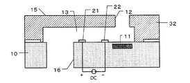
- 8A is a cross-sectional view of a recording element substrate of a liquid discharge head according to a fifth embodiment of the present invention
- FIG. 8B is a cross-sectional view taken along line AA in FIG. 8A
- FIG. 8C is a flow velocity in the same cross section as FIG. It is a schematic diagram which shows distribution.
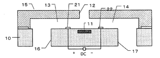
- the first electrode 21 and the second electrode 22 are connected to a DC power source DC. More specifically, the first electrode 21 is connected to the positive electrode of the DC power source DC, and the second electrode 22 is connected to the negative electrode of the DC power source DC.
- the dimensions of the first electrode 21 and the second electrode 22 are the same, but may be different as in the first embodiment.
- the electrodes are disposed on the substrate 10, but may be disposed on the back surface of the discharge port forming member 15. As shown in FIG. 8C, the flow velocity distribution shows a flow velocity distribution that is substantially close to the plug flow. The reason why such a flow velocity distribution occurs is as follows. When an electric field parallel to the wall surface is applied from the outside, the solid surface becomes negatively charged, and positive ions become excessive in the liquid near the interface.
- the liquid is locally positively charged, and ions in the electric double layer are subjected to a force in the direction of the electric field, causing ink to move near the wall. Since it is a direct current power source DC, it is necessary to drive the electrode with a voltage that does not cause electrolysis of the liquid (in the case of water, the voltage is preferably about 1 V or less), and the flow rate obtained is smaller than when using the alternating current power source AC. . However, since the ink flow can be generated simply by connecting the first electrode 21 and the second electrode 22 to the DC power source DC, a simpler configuration than the first embodiment can be obtained.
- FIG. 9A is a cross-sectional view of a recording element substrate of a liquid discharge head according to a modification of the fifth embodiment of the present invention
- FIG. 9B is a cross-sectional view taken along line AA in FIG. 9A
- FIG. 9C is the same as FIG. It is a schematic diagram which shows the flow-velocity distribution in a cross section.
- a first electrode 21 and a second electrode 22 are provided in the first liquid channel 13.
- the second liquid flow path 14 and the second through-hole 17 penetrating the substrate 10 are provided downstream of the pressure chamber 20 in the ink flow direction. .
- the first electrode 21 and the second electrode 22 are not arranged in the second liquid channel 14.
- FIG. 10A is a cross-sectional view of a recording element substrate of a liquid discharge head according to another modification of the fifth embodiment of the present invention
- FIG. 10B is a cross-sectional view taken along line AA in FIG. 10A
- FIG. It is a schematic diagram which shows the flow-velocity distribution in the same cross section.
- the second liquid flow path 14 and the second through-hole 17 penetrating the substrate 10 are provided downstream of the pressure chamber 20 in the ink flow direction. .
- the liquid discharge head which can reduce the viscosity increase of the liquid by the evaporation of the liquid from a discharge port and can arrange
Landscapes
- Physics & Mathematics (AREA)
- Geometry (AREA)
- Particle Formation And Scattering Control In Inkjet Printers (AREA)
- Ink Jet (AREA)
Abstract
液体吐出ヘッド1は、液体を吐出する複数の吐出口12が配列した吐出口列19と、液体を吐出するためのエネルギーを発生する複数のエネルギー発生素子11と、複数のエネルギー発生素子11が設けられた基板10と、基板10を貫通する複数の貫通口16が配列した貫通口列25と、貫通口列25と吐出口列19の間に位置し、吐出口列19のそれぞれの吐出口12と貫通口列25のそれぞれの貫通口16とに接続された直線状の複数の液流路13と、複数の液流路13の各々に設けられ、液体に電気浸透流を発生させる第1及び第2の電極21,22と、を有する。
Description
本発明は液体吐出ヘッドと液体の循環方法に関し、特に吐出口の近傍で液体を流動させるための構成に関する。
インク等の液体を吐出する液体吐出装置に用いられる液体吐出ヘッドにおいては、液体を吐出する吐出口から液体中の揮発成分が蒸発することで、吐出口付近の液体が増粘する。これによって、吐出される液滴の吐出速度が変化したり、着弾精度に影響がでたりすることがある。特に吐出を行った後の休止時間が長い場合、液体の粘度の増加が顕著になり、液体の固形成分が吐出口付近に固着し、この固形成分により液体の流体抵抗が増加し吐出不良となる場合もある。
このような液体の増粘現象に対する対策の1つとして、圧力室内にフレッシュな液体を流す方法が知られている。液体を流す手段として、第1にヘッド内の液体を差圧方式により循環させる方式がある。第2に交流電気浸透流(ACEOF)のようなμポンプを用いた方式がある(特許文献1)。
このような液体の増粘現象に対する対策の1つとして、圧力室内にフレッシュな液体を流す方法が知られている。液体を流す手段として、第1にヘッド内の液体を差圧方式により循環させる方式がある。第2に交流電気浸透流(ACEOF)のようなμポンプを用いた方式がある(特許文献1)。
特許文献1の構成の場合、圧力室内にフレッシュな液体を流入させることは可能である。しかし、液流路が共通の供給口から分岐して再び共通の供給口に合流する構成であるため、液流路の向きを途中で変える必要がある。このため、液流路が長くなり、大きな配置スペースを必要とする、従って、吐出口を高密度に配置することが困難であり記録素子の寸法が大きくなりやすい。
吐出口からの液体の蒸発による液体の増粘を軽減することが可能で、かつ吐出口を高密度に配置することが可能な液体吐出ヘッドを提供することを目的とする。本発明の液体吐出ヘッドは、液体を吐出する複数の吐出口が配列した吐出口列と、液体を吐出するためのエネルギーを発生する複数のエネルギー発生素子と、複数のエネルギー発生素子が設けられた基板と、基板を貫通する複数の貫通口が配列した貫通口列と貫通口列と吐出口列の間に位置し、吐出口列のそれぞれの吐出口と貫通口列のそれぞれの貫通口とに接続された直線状の複数の液流路と、複数の液流路の各々に設けられ、液体に電気浸透流を発生させる電極と、を有する。
以下、図面を参照して、本発明の実施形態に係る液体吐出ヘッドについて説明する。以下の各実施形態は、インクを吐出するインクジェット記録ヘッドとインクジェット記録装置を対象とするが、本発明はこれに限定されるものではない。本発明は、プリンタ、複写機、通信システムを有するファクシミリ、プリンタ部を有するワードプロセッサなどの装置、さらには各種処理装置と複合的に組み合わせた産業記録装置に適用可能である。本発明は例えば、バイオチップ作製、電子回路印刷、及び半導体ウエハーの回路パターンを形成するためのレジストの塗布などの用途としても用いることができる。
以下に述べる実施形態は本発明の好適な具体例であり、技術的に好ましい様々の限定が付けられている。しかし、本発明の思想に沿う限り、本発明は以下に述べる実施形態に限定されるものではない。
以下に述べる実施形態は本発明の好適な具体例であり、技術的に好ましい様々の限定が付けられている。しかし、本発明の思想に沿う限り、本発明は以下に述べる実施形態に限定されるものではない。
(第1の実施形態)
図1Aは本発明の第1の実施形態に係る液体吐出ヘッドの記録素子基板の斜視図である。図1Bは図1Aに示す記録素子基板の断面図、図1Cは図1BのA-A線に沿った断面図、図1Dは図1Cと同じ断面における流速分布を示す模式図である。
記録素子基板1は基板10と、吐出口形成部材15と、を有している。吐出口形成部材15は基板10に接合されている。基板10はインクが吐出するためのエネルギーを発生するエネルギー発生素子11を備えている。吐出口形成部材15には複数の吐出口12が配置されている、複数の吐出口12は一列に配列して吐出口列19を形成している。本実施形態の記録素子基板1は2列の吐出口列19を有しているが、吐出口列19の数はこれに限定されない。
図1Aは本発明の第1の実施形態に係る液体吐出ヘッドの記録素子基板の斜視図である。図1Bは図1Aに示す記録素子基板の断面図、図1Cは図1BのA-A線に沿った断面図、図1Dは図1Cと同じ断面における流速分布を示す模式図である。
記録素子基板1は基板10と、吐出口形成部材15と、を有している。吐出口形成部材15は基板10に接合されている。基板10はインクが吐出するためのエネルギーを発生するエネルギー発生素子11を備えている。吐出口形成部材15には複数の吐出口12が配置されている、複数の吐出口12は一列に配列して吐出口列19を形成している。本実施形態の記録素子基板1は2列の吐出口列19を有しているが、吐出口列19の数はこれに限定されない。
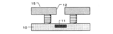
図1Bと図1Cを参照すると、基板10には、基板10を表面から裏面まで貫通する複数の第1の貫通口16が形成されている。吐出口形成部材15と基板10との間の空間には、第1の貫通孔16と圧力室20とを連通しインクが流通する複数の第1の液流路13が形成されている。第1の液流路13は直線状に延びている。吐出口形成部材15と基板10の間で、かつインク流に関し第1の液流路13の下流側には、それぞれがエネルギー発生素子11を内部に備えた複数の圧力室20が形成されている。本発明において圧力室20は隔壁32に挟まれた領域であり、かつエネルギー発生素子11が設けられた領域を示す。より広義的にはエネルギー発生素子11を駆動した際に圧力が作用する領域を示す。吐出口12は基板10の吐出口形成部材15と対向する面と垂直な方向においてエネルギー発生素子11と対向している。圧力室20と第1の貫通口16は対応する液流路毎ないし吐出口12毎に設けられている。従って、第1の貫通口16、第1の液流路13及び圧力室20は個々の吐出口12毎の独立した流路を形成している。複数の第1の貫通口16は第1の貫通口列25を形成している。第1の貫通口列25は吐出口列19に沿って延びている。
インクは第1の貫通口16から、第1の液流路13を通って圧力室20に供給される。圧力室20に供給されたインクはエネルギー発生素子11で加熱され、発生した気泡の圧力によって吐出口12から吐出する。
インクは第1の貫通口16から、第1の液流路13を通って圧力室20に供給される。圧力室20に供給されたインクはエネルギー発生素子11で加熱され、発生した気泡の圧力によって吐出口12から吐出する。
第1の液流路13には2種類の電極が設けられている。以下これらの電極を第1の電極21、第2の電極22と呼ぶ。第1の電極21と第2の電極22はいずれも基板10に設けられている。第1の電極21は交流電源ACの一端(+端子)に接続されており、第2の電極22は交流電源ACの他端(-端)に接続されている。第1の電極21はインクの流れ方向、すなわち第1の液流路13に沿った方向について、第2の電極22より寸法が小さい。一方、第1の電極21と第2の電極22のインクの流れ方向と直交する方向の寸法は同程度である。従って、第1の電極21は第2の電極22よりインクに面する面積が小さい。
第1の電極21と第2の電極22はそれぞれ第1の液流路13に複数個設けられ、かつ交互に設けられている。第1の電極21と第2の電極22は第1の貫通孔16から圧力室20に向かって、第1の電極21、第2の電極22、第1の電極21、第2の電極22・・の順で設けられている。しかし、第1の液流路13と第2の液流路14には、互いに隣接する第1の電極21と第2の電極22の組が少なくとも一つ設けられていればよい。複数の第1の電極21は共通の第1の配線24に接続されており、複数の第2の電極22は共通の第2の配線23に接続されている。第1の配線24および第2の配線23は、吐出口形成部材15の下部領域(隔壁32の下部領域)に設けられている。第1の配線24と第2の配線23は第1の液流路13を挟んで互いに反対側に配置されている。複数の第1の電極21と複数の第2の電極22は、第1の配線24と第2の配線23から互いに逆方向に櫛状に延びている。第2の配線23は第1の液流路13に沿って延び、さらに互いに隣接する第1の貫通口16の間を延び、第2の電極22からみて第1の貫通口16の先で第1の共通配線30に接続されている。第1の配線24は第1の液流路13に沿って延び、さらに互いに隣接するエネルギー発生素子11の間を延び、第1の電極21からみてエネルギー発生素子11の先で第2の共通配線31に接続されている。これによって第1の配線24と第2の配線23の錯綜が防止され、素子基板10の寸法の増加が抑制される。
第1の電極21と第2の電極22に通電すると第1の電極21と第2の電極22に交流電位が印加される。その結果、図1Dで示すように、液流路内に、基板10の表面側で流速が大きく、吐出口形成部材15に近づくにつれて流速がゼロに漸近する流速分布が生じる。この流速分布が生じる理由を、図2A~図2Dを参照して説明する。
第1の電極21と第2の電極には交流電圧が印加されるが、ここでは、第1の電極21に負電圧(-V)、第2の電極に正電圧(+V)が印加されているタイミングを考える。図2Aにおける第1の電極21と第2の電極は同じ寸法であるとする。図2Aに示すように、第1の電極21と第2の電極には電気二重層が発生する。すなわち、第1の電極21に負電圧(-V)が掛かり、第1の電極21に接するインクが正電荷を帯びて,電気二重層が形成される。同様に、第2の電極22に正電圧(+V))が掛かり、電極22に接するインクが負電荷を帯びて,電気二重層が形成される。
インク中には第2の電極22から第1の電極21を向く半円状の電界Eが形成される。この電界は第1の電極21と第2の電極22の中間の線に関し対称形となる。第1及び第2の電極21,22の表面では第1及び第2の電極21,22の表面と平行な電界成分E1が生じる。この電界成分E1は第1及び第2の電極21,22上に誘起された電荷にクーロン力を及ぼす。電界成分E1は電極間ギャップに近い位置では図中左向きとなる。正電荷は電界と同じ向きの力を受けるため、図2Bに示すように、第1の電極21に接するインクが図中左向きに流れる回転渦F1が生じる。負電荷は電界と逆向きの力を受けるため、第2の電極22に接するインクが図中右向きに流れる回転渦F2が生じる。インクは電極間ギャップから離れる方向に流れるため、電極間ギャップにはインクを補充するようなインク流れF3が発生する。また、電極の電極間ギャップから離れた方の端部では電界の向きが逆になるため、インクが電極間ギャップに向かって流れる回転渦F4が生じる。ただし、電界が弱いためインクが受けるクーロン力は小さい。この結果、電極間ギャップから第1及び第2の電極21,22に向かい、第1及び第2の電極21,22上を電極間ギャップから離れる向きに流れる撹拌流のような流れが形成される。この流れは第1の電極21と第2の電極22で左右対称形となる。
インク中には第2の電極22から第1の電極21を向く半円状の電界Eが形成される。この電界は第1の電極21と第2の電極22の中間の線に関し対称形となる。第1及び第2の電極21,22の表面では第1及び第2の電極21,22の表面と平行な電界成分E1が生じる。この電界成分E1は第1及び第2の電極21,22上に誘起された電荷にクーロン力を及ぼす。電界成分E1は電極間ギャップに近い位置では図中左向きとなる。正電荷は電界と同じ向きの力を受けるため、図2Bに示すように、第1の電極21に接するインクが図中左向きに流れる回転渦F1が生じる。負電荷は電界と逆向きの力を受けるため、第2の電極22に接するインクが図中右向きに流れる回転渦F2が生じる。インクは電極間ギャップから離れる方向に流れるため、電極間ギャップにはインクを補充するようなインク流れF3が発生する。また、電極の電極間ギャップから離れた方の端部では電界の向きが逆になるため、インクが電極間ギャップに向かって流れる回転渦F4が生じる。ただし、電界が弱いためインクが受けるクーロン力は小さい。この結果、電極間ギャップから第1及び第2の電極21,22に向かい、第1及び第2の電極21,22上を電極間ギャップから離れる向きに流れる撹拌流のような流れが形成される。この流れは第1の電極21と第2の電極22で左右対称形となる。
一方、図2C,図2Dでは、第2の電極22の流路方向寸法が第1の電極21の流路方向寸法より大きくなっている。このため、第1の電極21と第2の電極22で電界分布が異なる。第1の電極21の近傍では流速の早い小さな回転渦F5が形成される。第2の電極22の近傍では、電位の低い部分で流速の遅い小さな回転渦F7が形成され、電位の高い部分で流速の早い大きな回転渦F6が形成される。その結果、第1の電極21から電極間ギャップにインクが引き込まれ、第1の電極21から第2の電極22に向けてインクが流れるインク流が生じる。
以上は第1の電極21に正電圧(+V)、第2の電極に負電圧(-V)が印加されていても同じである。すなわち、印加電圧の極性が反転しても、電荷の符号と電界の向きが共に反転するため、生じる流れの向きは変化しない。従って、流路方向寸法が小さい第1の電極21から流路方向寸法が大きい第2の電極22に向かう定常的な流れが生じることになる。
以上は第1の電極21に正電圧(+V)、第2の電極に負電圧(-V)が印加されていても同じである。すなわち、印加電圧の極性が反転しても、電荷の符号と電界の向きが共に反転するため、生じる流れの向きは変化しない。従って、流路方向寸法が小さい第1の電極21から流路方向寸法が大きい第2の電極22に向かう定常的な流れが生じることになる。
このような電気浸透流により、インクを第1の液流路13から圧力室20に向けて流す駆動力が発生する。すなわち、第1の液流路13に設けられた第1の電極21と第2の電極22によって発生した電気浸透流により、インクは第1の貫通口16から第1の液流路13を通って圧力室20に流入する。エネルギー発生素子11が作動しているときは、圧力室20に流入したインクの一部が吐出口12から吐出される。
エネルギー発生素子11が作動していないときにも、第1の電極21と第2の電極22に接続された交流電源ACによる電気浸透流が生じているため、第1の液流路13と圧力室20内のインクが撹拌される。このため、仮に圧力室20の内部でインクが濃縮しても、圧力室20内における濃縮インクの滞留を抑制することができる。従って、吐出口12からは増粘していない、または増粘の程度が小さい比較的フレッシュなインクを吐出することができ、画像の色ムラを低減することが可能となる。
また、第1の電極21に接続された第1の配線24を第1の貫通口16の間に設けることができるため、第1の電極21を第1の貫通口と吐出口12の間の第1の液流路13に配置することができる。そのため、第1及び第2の電極21,22と吐出口12を高密度に配置することが可能であり、記録素子基板の寸法を縮小することが容易である。
以上、本実施形態では、基板10に、インクを供給するための複数の貫通孔16を設け、貫通孔16と圧力室20とを連通する液流路(第1の液流路13)に第1および第2の電極を設け電気浸透流を発生させる構成とした。このような構成により基板内における液流路等のレイアウトの自由度が向上し、吐出口が高密度に配置され、電気浸透流を発生可能な液体吐出ヘッドの提供が可能となる。
エネルギー発生素子11が作動していないときにも、第1の電極21と第2の電極22に接続された交流電源ACによる電気浸透流が生じているため、第1の液流路13と圧力室20内のインクが撹拌される。このため、仮に圧力室20の内部でインクが濃縮しても、圧力室20内における濃縮インクの滞留を抑制することができる。従って、吐出口12からは増粘していない、または増粘の程度が小さい比較的フレッシュなインクを吐出することができ、画像の色ムラを低減することが可能となる。
また、第1の電極21に接続された第1の配線24を第1の貫通口16の間に設けることができるため、第1の電極21を第1の貫通口と吐出口12の間の第1の液流路13に配置することができる。そのため、第1及び第2の電極21,22と吐出口12を高密度に配置することが可能であり、記録素子基板の寸法を縮小することが容易である。
以上、本実施形態では、基板10に、インクを供給するための複数の貫通孔16を設け、貫通孔16と圧力室20とを連通する液流路(第1の液流路13)に第1および第2の電極を設け電気浸透流を発生させる構成とした。このような構成により基板内における液流路等のレイアウトの自由度が向上し、吐出口が高密度に配置され、電気浸透流を発生可能な液体吐出ヘッドの提供が可能となる。
(第2の実施形態)
図3A~図3Cを用いて、本発明の第2の実施形態に係る液体吐出ヘッドの記録素子基板の構成を説明する。なお、以下の説明においては第1の実施形態との違いを主に説明するため、具体的な説明を省略した個所については第1の実施形態の説明を参照されたい。
図3Aは本発明の第2の実施形態に係る液体吐出ヘッドの記録素子基板の断面図、図3Bは図3AのA-A線に沿った断面図、図3Cは図3Bと同じ断面における流速分布を示す模式図である。
本実施形態では、インク流れ方向に関して圧力室20の下流に第2の液流路14が設けられている。第2の液流路14には第1の電極21と第2の電極22は配置されていない。基板10には、基板10を表面から裏面まで貫通する複数の第2の貫通口17が形成されている。この結果、吐出口12が設けられた圧力室20が第1の液流路13と第2の液流路14の間に配置されている。また、第1の貫通口16、第1の液流路13、圧力室20、第2の液流路14及び第2の貫通口17は個々の吐出口12毎の独立した流路を形成している。吐出口12で吐出されなかったインクは第2の液流路14を通って第2の貫通口17へと流れる。液体吐出ヘッドの外部に流出したインクは記録装置のインクタンク等を経由した後に再度液体吐出ヘッドに流入する。このように、本発明の形態により圧力室20内のインクは圧力室20の外部との間で循環される。尚、本発明においては液体吐出ヘッドの外部との間で循環される構成だけでなく、液体吐出ヘッドの内部でインクが循環(圧力室20の内部と外部との間でインクが流動)する構成においても適用できる。
このような構成により、インクが吐出していないときでも圧力室20を通過するインク流が形成され、増粘したインクの吐出口12での滞留を抑制することができる。従って、インクの増粘を軽減し画像の色ムラを低減することができる。
図3A~図3Cを用いて、本発明の第2の実施形態に係る液体吐出ヘッドの記録素子基板の構成を説明する。なお、以下の説明においては第1の実施形態との違いを主に説明するため、具体的な説明を省略した個所については第1の実施形態の説明を参照されたい。
図3Aは本発明の第2の実施形態に係る液体吐出ヘッドの記録素子基板の断面図、図3Bは図3AのA-A線に沿った断面図、図3Cは図3Bと同じ断面における流速分布を示す模式図である。
本実施形態では、インク流れ方向に関して圧力室20の下流に第2の液流路14が設けられている。第2の液流路14には第1の電極21と第2の電極22は配置されていない。基板10には、基板10を表面から裏面まで貫通する複数の第2の貫通口17が形成されている。この結果、吐出口12が設けられた圧力室20が第1の液流路13と第2の液流路14の間に配置されている。また、第1の貫通口16、第1の液流路13、圧力室20、第2の液流路14及び第2の貫通口17は個々の吐出口12毎の独立した流路を形成している。吐出口12で吐出されなかったインクは第2の液流路14を通って第2の貫通口17へと流れる。液体吐出ヘッドの外部に流出したインクは記録装置のインクタンク等を経由した後に再度液体吐出ヘッドに流入する。このように、本発明の形態により圧力室20内のインクは圧力室20の外部との間で循環される。尚、本発明においては液体吐出ヘッドの外部との間で循環される構成だけでなく、液体吐出ヘッドの内部でインクが循環(圧力室20の内部と外部との間でインクが流動)する構成においても適用できる。
このような構成により、インクが吐出していないときでも圧力室20を通過するインク流が形成され、増粘したインクの吐出口12での滞留を抑制することができる。従って、インクの増粘を軽減し画像の色ムラを低減することができる。
(第3の実施形態)
図4A~図4Cを用いて、本発明の第3の実施形態に係る液体吐出ヘッドの記録素子基板の構成を説明する。なお、以下の説明においては第2の実施形態との違いを主に説明するため、具体的な説明を省略した個所については第2の実施形態の説明を参照されたい。
図4Aは本発明の第3の実施形態に係る液体吐出ヘッドの記録素子基板の断面図、図4Bは図4AのA-A線に沿った断面図、図4Cは図4Bと同じ断面における流速分布を示す模式図である。
本実施形態では、第2の液流路14に第1の電極21と第2の電極22が配置されている。その他の構成は第2の実施形態と同様である。第1の液流路13と第2の液流路14のそれぞれに第1の電極21と第2の電極22が配置されているため、吐出口12の内部で濃縮したインクを排出させる効果が大きい。そのため、濃縮インクが圧力室20内部に留まり難い。従って、インクの増粘をさらに軽減し画像の色ムラを低減することが可能となる。
図4A~図4Cを用いて、本発明の第3の実施形態に係る液体吐出ヘッドの記録素子基板の構成を説明する。なお、以下の説明においては第2の実施形態との違いを主に説明するため、具体的な説明を省略した個所については第2の実施形態の説明を参照されたい。
図4Aは本発明の第3の実施形態に係る液体吐出ヘッドの記録素子基板の断面図、図4Bは図4AのA-A線に沿った断面図、図4Cは図4Bと同じ断面における流速分布を示す模式図である。
本実施形態では、第2の液流路14に第1の電極21と第2の電極22が配置されている。その他の構成は第2の実施形態と同様である。第1の液流路13と第2の液流路14のそれぞれに第1の電極21と第2の電極22が配置されているため、吐出口12の内部で濃縮したインクを排出させる効果が大きい。そのため、濃縮インクが圧力室20内部に留まり難い。従って、インクの増粘をさらに軽減し画像の色ムラを低減することが可能となる。
(第4の実施形態)
図5A~図7Cを用いて、本発明の第4の実施形態に係る液体吐出ヘッドの記録素子基板の構成を説明する。なお、以下の説明においては第1~3の実施形態との違いを主に説明するため、具体的な説明を省略した個所については第1~3の実施形態の説明を参照されたい。
図5Aは本発明の第4の実施形態に係る液体吐出ヘッドの記録素子基板の断面図、図5Bは図5AのA-A線に沿った断面図、図5Cは図5Bと同じ断面における流速分布を示す模式図である。
本実施形態では、第1の電極21と第2の電極22が吐出口形成部材15の裏面に配置されている。裏面とは吐出口形成部材15の圧力室20に面する面を意味する。従って、電気二重層の充填が吐出口形成部材15の裏面の電極上で生じる。そのため、図5Cに示すように、液流路内で、吐出口形成部材15の裏面で流速が大きく、基板10の表面に近づくにつれて流速がゼロに漸近する流速分布が得られる。第1の実施形態と同じ交流電源ACと同じ周波数で第1の電極21と第2の電極22を駆動する場合、吐出口形成部材15の裏面側の流速が大きいため、吐出口12内のインクの濃縮を解消し易い。従って、インクの増粘をさらに効率的に軽減することができる。
図5A~図7Cを用いて、本発明の第4の実施形態に係る液体吐出ヘッドの記録素子基板の構成を説明する。なお、以下の説明においては第1~3の実施形態との違いを主に説明するため、具体的な説明を省略した個所については第1~3の実施形態の説明を参照されたい。
図5Aは本発明の第4の実施形態に係る液体吐出ヘッドの記録素子基板の断面図、図5Bは図5AのA-A線に沿った断面図、図5Cは図5Bと同じ断面における流速分布を示す模式図である。
本実施形態では、第1の電極21と第2の電極22が吐出口形成部材15の裏面に配置されている。裏面とは吐出口形成部材15の圧力室20に面する面を意味する。従って、電気二重層の充填が吐出口形成部材15の裏面の電極上で生じる。そのため、図5Cに示すように、液流路内で、吐出口形成部材15の裏面で流速が大きく、基板10の表面に近づくにつれて流速がゼロに漸近する流速分布が得られる。第1の実施形態と同じ交流電源ACと同じ周波数で第1の電極21と第2の電極22を駆動する場合、吐出口形成部材15の裏面側の流速が大きいため、吐出口12内のインクの濃縮を解消し易い。従って、インクの増粘をさらに効率的に軽減することができる。
本実施形態を第2、第3の実施形態に適用することもできる。図6Aは本発明の第4の実施形態の変形例に係る液体吐出ヘッドの記録素子基板の断面図、図6Bは図6AのA-A線に沿った断面図、図6Cは図6Bと同じ断面における流速分布を示す模式図である。本実施形態では第2の実施形態と同様、インク流れ方向に関して圧力室20の下流に、第2の液流路14と、基板10を貫通する第2の貫通口17と、が設けられている。第2の液流路14には第1の電極21と第2の電極22は配置されていない。本実施形態によれば、第2の実施形態と同様、インクが吐出していないときでも圧力室20を通過するインク流が形成され、画像の色ムラを低減することができる。
図7Aは本発明の第4の実施形態の他の変形例に係る液体吐出ヘッドの記録素子基板の断面図、図7Bは図7AのA-A線に沿った断面図、図7Cは図7Bと同じ断面における流速分布を示す模式図である。本実施形態では、第3の実施形態と同様、インク流れ方向に関して圧力室20の下流に、第2の液流路14と、基板10を貫通する第2の貫通口17と、が設けられている。また、第2の液流路14には第1の電極21と第2の電極22が配置されている。従って、第3の実施形態と同様、吐出口12の内部で濃縮したインクを排出させる効果が大きく、画像の色ムラを一層低減することが可能となる。
上述の第1~第4の実施形態をさらに変形させることもできる。図示は省略するが、例えば、第1の液流路13の第1の電極21と第2の電極22を吐出口形成部材15の裏面に配置し、第2の液流路14の第1の電極21と第2の電極22を基板10の表面に配置することができる。これによって、吐出口形成部材15の裏面の流速を高め、吐出口12内部の濃縮を抑制することが容易となる。また、第2の液流路14の電極を基板10上に配置することで濃縮インクを流出させることが容易となる。
図7Aは本発明の第4の実施形態の他の変形例に係る液体吐出ヘッドの記録素子基板の断面図、図7Bは図7AのA-A線に沿った断面図、図7Cは図7Bと同じ断面における流速分布を示す模式図である。本実施形態では、第3の実施形態と同様、インク流れ方向に関して圧力室20の下流に、第2の液流路14と、基板10を貫通する第2の貫通口17と、が設けられている。また、第2の液流路14には第1の電極21と第2の電極22が配置されている。従って、第3の実施形態と同様、吐出口12の内部で濃縮したインクを排出させる効果が大きく、画像の色ムラを一層低減することが可能となる。
上述の第1~第4の実施形態をさらに変形させることもできる。図示は省略するが、例えば、第1の液流路13の第1の電極21と第2の電極22を吐出口形成部材15の裏面に配置し、第2の液流路14の第1の電極21と第2の電極22を基板10の表面に配置することができる。これによって、吐出口形成部材15の裏面の流速を高め、吐出口12内部の濃縮を抑制することが容易となる。また、第2の液流路14の電極を基板10上に配置することで濃縮インクを流出させることが容易となる。
(第5の実施形態)
図8A~図10Cを用いて、本発明の第5の実施形態に係る液体吐出ヘッドの記録素子基板の構成を説明する。なお、以下の説明においては第1~3の実施形態との違いを主に説明するため、具体的な説明を省略した個所については第1~3の実施形態の説明を参照されたい。
図8Aは本発明の第5の実施形態に係る液体吐出ヘッドの記録素子基板の断面図、図8Bは図8AのA-A線に沿った断面図、図8Cは図8Bと同じ断面における流速分布を示す模式図である。
本実施形態では、第1の電極21と第2の電極22は直流電源DCに接続されている。より具体的には、第1の電極21が直流電源DCの正極に接続され、第2の電極22が直流電源DCの負極に接続されている。第1の電極21と第2の電極22の寸法は同じであるが、第1の実施形態のように異なっていてもよい。電極は基板10上に配置されているが、吐出口形成部材15の裏面に配置されてもよい。
図8Cに示すように、流速分布は概ね栓流に近い流速分布を示す。このような流速分布が生じる理由は以下の通りである。壁面に平行な電界が外部から印加されると、固体表面が負に帯電し、界面近傍の液体中では正イオンが過剰になる。そのため、局所的に液体が正に帯電し電気二重層のイオンが電界の方向に力を受け、壁近傍でインクの移動が生じるためである。直流電源DCのため、液体の電気分解が生じない電圧で電極を駆動する必要があり(水の場合、電圧は約1V以下が好ましい)、交流電源ACを用いる場合と比べて得られる流速は小さい。しかし、第1の電極21と第2の電極22を直流電源DCに接続するだけでインク流れを発生させることができるため、第1の実施形態よりシンプルな構成が得られる。
図8A~図10Cを用いて、本発明の第5の実施形態に係る液体吐出ヘッドの記録素子基板の構成を説明する。なお、以下の説明においては第1~3の実施形態との違いを主に説明するため、具体的な説明を省略した個所については第1~3の実施形態の説明を参照されたい。
図8Aは本発明の第5の実施形態に係る液体吐出ヘッドの記録素子基板の断面図、図8Bは図8AのA-A線に沿った断面図、図8Cは図8Bと同じ断面における流速分布を示す模式図である。
本実施形態では、第1の電極21と第2の電極22は直流電源DCに接続されている。より具体的には、第1の電極21が直流電源DCの正極に接続され、第2の電極22が直流電源DCの負極に接続されている。第1の電極21と第2の電極22の寸法は同じであるが、第1の実施形態のように異なっていてもよい。電極は基板10上に配置されているが、吐出口形成部材15の裏面に配置されてもよい。
図8Cに示すように、流速分布は概ね栓流に近い流速分布を示す。このような流速分布が生じる理由は以下の通りである。壁面に平行な電界が外部から印加されると、固体表面が負に帯電し、界面近傍の液体中では正イオンが過剰になる。そのため、局所的に液体が正に帯電し電気二重層のイオンが電界の方向に力を受け、壁近傍でインクの移動が生じるためである。直流電源DCのため、液体の電気分解が生じない電圧で電極を駆動する必要があり(水の場合、電圧は約1V以下が好ましい)、交流電源ACを用いる場合と比べて得られる流速は小さい。しかし、第1の電極21と第2の電極22を直流電源DCに接続するだけでインク流れを発生させることができるため、第1の実施形態よりシンプルな構成が得られる。
本実施形態を第2、第3の実施形態に適用することもできる。図9Aは本発明の第5の実施形態の変形例に係る液体吐出ヘッドの記録素子基板の断面図、図9Bは図9AのA-A線に沿った断面図、図9Cは図9Bと同じ断面における流速分布を示す模式図である。第1の液流路13に第1の電極21と第2の電極22が設けられている。本実施形態では第2の実施形態と同様、インク流れ方向に関して圧力室20の下流に、第2の液流路14と、基板10を貫通する第2の貫通口17と、が設けられている。第2の液流路14には第1の電極21と第2の電極22は配置されていない。本実施形態によれば、第2の実施形態と同様、インクが吐出していないときでも圧力室20を通過するインク流が形成され、画像の色ムラを低減することができる。
図10Aは本発明の第5の実施形態の他の変形例に係る液体吐出ヘッドの記録素子基板の断面図、図10Bは図10AのA-A線に沿った断面図、図10Cは図10Bと同じ断面における流速分布を示す模式図である。本実施形態では第3の実施形態と同様、インク流れ方向に関して圧力室20の下流に、第2の液流路14と、基板10を貫通する第2の貫通口17と、が設けられている。また、第2の液流路14には第1の電極21と第2の電極22が配置されている。従って、吐出口12の内部で濃縮したインクを排出させる効果が大きく、画像の色ムラを一層低減することが可能となる。
本発明によれば、吐出口からの液体の蒸発による液体の増粘を軽減することが可能で、かつ吐出口を高密度に配置することが可能な液体吐出ヘッドを提供することができる。
図10Aは本発明の第5の実施形態の他の変形例に係る液体吐出ヘッドの記録素子基板の断面図、図10Bは図10AのA-A線に沿った断面図、図10Cは図10Bと同じ断面における流速分布を示す模式図である。本実施形態では第3の実施形態と同様、インク流れ方向に関して圧力室20の下流に、第2の液流路14と、基板10を貫通する第2の貫通口17と、が設けられている。また、第2の液流路14には第1の電極21と第2の電極22が配置されている。従って、吐出口12の内部で濃縮したインクを排出させる効果が大きく、画像の色ムラを一層低減することが可能となる。
本発明によれば、吐出口からの液体の蒸発による液体の増粘を軽減することが可能で、かつ吐出口を高密度に配置することが可能な液体吐出ヘッドを提供することができる。
この出願は2016年3月29日に出願された日本国特許出願番号2016-065627の優先権を主張するものであり、それらの内容を引用してこの出願の一部とするものである。
1 記録素子基板
10 基板
11 エネルギー発生素子
12 吐出口
13 第1の液流路
14 第2の液流路
15 吐出口形成部材
16 第1の貫通口
17 第2の貫通口
20 圧力室
21 第1の電極
22 第2の電極
23 第2の配線
24 第1の配線
10 基板
11 エネルギー発生素子
12 吐出口
13 第1の液流路
14 第2の液流路
15 吐出口形成部材
16 第1の貫通口
17 第2の貫通口
20 圧力室
21 第1の電極
22 第2の電極
23 第2の配線
24 第1の配線
Claims (13)
- 液体を吐出する複数の吐出口が配列した吐出口列と、
前記液体を吐出するためのエネルギーを発生する複数のエネルギー発生素子と、
前記複数のエネルギー発生素子が設けられた基板と、
前記基板を貫通する複数の貫通口が配列した貫通口列と
前記貫通口列と前記吐出口列の間に位置し、前記吐出口列のそれぞれの吐出口と前記貫通口列のそれぞれの貫通口とに接続された直線状の複数の液流路と、
前記複数の液流路の各々に設けられ、液体に電気浸透流を発生させる電極と、を有する、液体吐出ヘッド。 - 液体を吐出する吐出口と、
前記液体を吐出するためのエネルギーを発生するエネルギー発生素子と、
前記エネルギー発生素子が設けられた基板と、
前記基板を貫通する貫通口と、
前記吐出口と前記貫通口とに接続された直線状の液流路と、
前記液流路に設けられ、液体に電気浸透流を発生させる電極と、を有する、液体吐出ヘッド。 - 液体を吐出する複数の吐出口が配列した吐出口列と、
前記液体を吐出するためのエネルギーを発生する複数のエネルギー発生素子と、
前記複数のエネルギー発生素子が設けられた基板と、
前記基板を貫通する複数の貫通口が配列した貫通口列と、
前記吐出口列と前記貫通口列の間に位置し、前記吐出口列のそれぞれの吐出口と前記貫通口列のそれぞれの貫通口とに接続された複数の液流路と、
前記複数の液流路の各々に設けられ、前記液体に電気浸透流を発生させる電極と、
前記電極に接続され、互いに隣り合う前記貫通口の間を通る配線と、を有する、液体吐出ヘッド。 - 前記電極は前記基板に配置されている、請求項1から3のいずれか1項に記載の液体吐出ヘッド。
- 前記吐出口が設けられた吐出口形成部材を有し、前記電極は前記吐出口形成部材に配置されている、請求項1から4のいずれか1項に記載の液体吐出ヘッド。
- 前記電極は第1の電極と第2の電極を含み、前記第1の電極は交流電源の一端に接続され、前記第2の電極は前記交流電源の他端に接続されている、請求項1から5のいずれか1項に記載の液体吐出ヘッド。
- 前記第1の電極と前記第2の電極は交互に配置され、前記第1の電極と前記第2の電極の前記液流路に沿った方向の寸法が互いに異なる、請求項6に記載の液体吐出ヘッド。
- 前記電極は第1の電極と第2の電極を含み、前記第1の電極は直流電源の一端に接続され、前記第2の電極は前記直流電源の他端に接続されている、請求項1から5のいずれか1項に記載の液体吐出ヘッド。
- 前記吐出口に関し前記液流路の反対側に、前記吐出口と流通する第2の液流路を有している、請求項1から8のいずれか1項に記載の液体吐出ヘッド。
- 液体に電気浸透流を発生させる第2の電極が前記第2の液流路に配置されている、請求項9に記載の液体吐出ヘッド。
- 前記吐出口に関して前記液流路の反対側に、前記基板を貫通する第2の貫通口を有し、前記第2の液流路は、前記吐出口と前記第2の貫通口との間に設けられている、請求項9または10に記載の液体吐出ヘッド。
- 前記エネルギー発生素子を内部に備える圧力室を有し、当該圧力室内の液体は当該圧力室の外部との間で循環される、請求項1から3のいずれか1項に記載の液体吐出ヘッド。
- 液体を吐出するためのエネルギーを発生するエネルギー発生素子が設けられた基板を貫通し、貫通口列をなす複数の貫通口に液体を充填することと、
液体を吐出する複数の吐出口が配列した吐出口列と前記貫通口列の間に位置し、前記吐出口列のそれぞれの吐出口と前記貫通口列のそれぞれの貫通口とに接続された複数の直線状の液流路に液体を充填することと、
前記液流路に位置する電極に通電し、前記液体に電気浸透流を発生させることと、を有する液体の循環方法。
Priority Applications (2)
| Application Number | Priority Date | Filing Date | Title |
|---|---|---|---|
| CN201780021459.1A CN109311321B (zh) | 2016-03-29 | 2017-03-24 | 液体喷射头和用于循环液体的方法 |
| US16/140,896 US10703105B2 (en) | 2016-03-29 | 2018-09-25 | Liquid ejection head and method for circulating liquid |
Applications Claiming Priority (2)
| Application Number | Priority Date | Filing Date | Title |
|---|---|---|---|
| JP2016-065627 | 2016-03-29 | ||
| JP2016065627A JP6736324B2 (ja) | 2016-03-29 | 2016-03-29 | 液体吐出ヘッド |
Related Child Applications (1)
| Application Number | Title | Priority Date | Filing Date |
|---|---|---|---|
| US16/140,896 Continuation US10703105B2 (en) | 2016-03-29 | 2018-09-25 | Liquid ejection head and method for circulating liquid |
Publications (1)
| Publication Number | Publication Date |
|---|---|
| WO2017170258A1 true WO2017170258A1 (ja) | 2017-10-05 |
Family
ID=59965569
Family Applications (1)
| Application Number | Title | Priority Date | Filing Date |
|---|---|---|---|
| PCT/JP2017/012113 Ceased WO2017170258A1 (ja) | 2016-03-29 | 2017-03-24 | 液体吐出ヘッド及び液体の循環方法 |
Country Status (4)
| Country | Link |
|---|---|
| US (1) | US10703105B2 (ja) |
| JP (1) | JP6736324B2 (ja) |
| CN (1) | CN109311321B (ja) |
| WO (1) | WO2017170258A1 (ja) |
Cited By (1)
| Publication number | Priority date | Publication date | Assignee | Title |
|---|---|---|---|---|
| JP2021054008A (ja) * | 2019-10-01 | 2021-04-08 | キヤノン株式会社 | 液体吐出ヘッド |
Families Citing this family (7)
| Publication number | Priority date | Publication date | Assignee | Title |
|---|---|---|---|---|
| JP6910911B2 (ja) | 2017-09-27 | 2021-07-28 | キヤノン株式会社 | 液体吐出ヘッド |
| JP7039231B2 (ja) | 2017-09-28 | 2022-03-22 | キヤノン株式会社 | 液体吐出ヘッドおよび液体吐出装置 |
| JP7134733B2 (ja) * | 2018-06-25 | 2022-09-12 | キヤノン株式会社 | 記録素子基板、液体吐出ヘッド、および液体吐出装置 |
| JP7134752B2 (ja) | 2018-07-06 | 2022-09-12 | キヤノン株式会社 | 液体吐出ヘッド |
| JP7237531B2 (ja) | 2018-11-02 | 2023-03-13 | キヤノン株式会社 | 液体吐出ヘッドとその製造方法 |
| US11453213B2 (en) | 2018-12-28 | 2022-09-27 | Canon Kabushiki Kaisha | Driving method of liquid feeding apparatus |
| JP7292876B2 (ja) | 2018-12-28 | 2023-06-19 | キヤノン株式会社 | 液体吐出ヘッドおよび液体吐出装置 |
Citations (4)
| Publication number | Priority date | Publication date | Assignee | Title |
|---|---|---|---|---|
| US6244694B1 (en) * | 1999-08-03 | 2001-06-12 | Hewlett-Packard Company | Method and apparatus for dampening vibration in the ink in computer controlled printers |
| US20130146459A1 (en) * | 2009-06-16 | 2013-06-13 | Massachusetts Institute Of Technology | Multiphase non-linear electrokinetic devices |
| WO2013130039A1 (en) * | 2012-02-28 | 2013-09-06 | Hewlett-Packard Development Company, L.P. | Fluid ejection device with aceo pump |
| JP2014531349A (ja) * | 2011-09-28 | 2014-11-27 | ヒューレット−パッカード デベロップメント カンパニー エル.ピー.Hewlett‐Packard Development Company, L.P. | 流体吐出デバイスにおけるスロット間の循環 |
Family Cites Families (12)
| Publication number | Priority date | Publication date | Assignee | Title |
|---|---|---|---|---|
| JP4011952B2 (ja) | 2002-04-04 | 2007-11-21 | キヤノン株式会社 | 液体吐出ヘッドおよび該液体吐出ヘッドを備える記録装置 |
| US7708873B2 (en) * | 2006-02-02 | 2010-05-04 | Massachusetts Institute Of Technology | Induced-charge electro-osmotic microfluidic devices |
| AU2008345138B2 (en) * | 2007-12-23 | 2014-05-29 | Advanced Liquid Logic, Inc. | Droplet actuator configurations and methods of conducting droplet operations |
| JP5225132B2 (ja) * | 2009-02-06 | 2013-07-03 | キヤノン株式会社 | 液体吐出ヘッドおよびインクジェット記録装置 |
| CN101670998B (zh) * | 2009-09-16 | 2011-10-26 | 哈尔滨工业大学 | 点面电极系统及利用该系统进行微流体驱动的方法 |
| CN103909731B (zh) * | 2013-01-07 | 2016-01-13 | 中国科学院理化技术研究所 | 电渗喷墨装置 |
| JP6410528B2 (ja) * | 2014-08-29 | 2018-10-24 | キヤノン株式会社 | 液体吐出ヘッドとそれを用いたヘッドユニット |
| JP6468929B2 (ja) | 2015-04-09 | 2019-02-13 | キヤノン株式会社 | 液体吐出ヘッドおよび液体吐出装置 |
| US10040290B2 (en) | 2016-01-08 | 2018-08-07 | Canon Kabushiki Kaisha | Liquid ejection head, liquid ejection apparatus, and method of supplying liquid |
| JP6669393B2 (ja) | 2016-03-25 | 2020-03-18 | キヤノン株式会社 | 液体吐出ヘッド、液体吐出装置、および液体吐出ヘッドの温度制御方法 |
| JP7019318B2 (ja) | 2017-06-29 | 2022-02-15 | キヤノン株式会社 | 液体吐出ヘッドおよび液体吐出装置 |
| JP7057071B2 (ja) | 2017-06-29 | 2022-04-19 | キヤノン株式会社 | 液体吐出モジュール |
-
2016
- 2016-03-29 JP JP2016065627A patent/JP6736324B2/ja active Active
-
2017
- 2017-03-24 WO PCT/JP2017/012113 patent/WO2017170258A1/ja not_active Ceased
- 2017-03-24 CN CN201780021459.1A patent/CN109311321B/zh active Active
-
2018
- 2018-09-25 US US16/140,896 patent/US10703105B2/en active Active
Patent Citations (4)
| Publication number | Priority date | Publication date | Assignee | Title |
|---|---|---|---|---|
| US6244694B1 (en) * | 1999-08-03 | 2001-06-12 | Hewlett-Packard Company | Method and apparatus for dampening vibration in the ink in computer controlled printers |
| US20130146459A1 (en) * | 2009-06-16 | 2013-06-13 | Massachusetts Institute Of Technology | Multiphase non-linear electrokinetic devices |
| JP2014531349A (ja) * | 2011-09-28 | 2014-11-27 | ヒューレット−パッカード デベロップメント カンパニー エル.ピー.Hewlett‐Packard Development Company, L.P. | 流体吐出デバイスにおけるスロット間の循環 |
| WO2013130039A1 (en) * | 2012-02-28 | 2013-09-06 | Hewlett-Packard Development Company, L.P. | Fluid ejection device with aceo pump |
Cited By (2)
| Publication number | Priority date | Publication date | Assignee | Title |
|---|---|---|---|---|
| JP2021054008A (ja) * | 2019-10-01 | 2021-04-08 | キヤノン株式会社 | 液体吐出ヘッド |
| JP7419008B2 (ja) | 2019-10-01 | 2024-01-22 | キヤノン株式会社 | 液体吐出ヘッド |
Also Published As
| Publication number | Publication date |
|---|---|
| US10703105B2 (en) | 2020-07-07 |
| JP2017177436A (ja) | 2017-10-05 |
| JP6736324B2 (ja) | 2020-08-05 |
| US20190023018A1 (en) | 2019-01-24 |
| CN109311321A (zh) | 2019-02-05 |
| CN109311321B (zh) | 2020-08-11 |
Similar Documents
| Publication | Publication Date | Title |
|---|---|---|
| KR102223257B1 (ko) | 액체 토출 헤드 및 액체의 순환 방법 | |
| JP6736324B2 (ja) | 液体吐出ヘッド | |
| US8205968B2 (en) | Liquid discharge head and liquid discharge method | |
| KR20190002321A (ko) | 액체 토출 헤드 및 액체 토출 장치 | |
| JP2018103601A (ja) | 液体噴射ヘッドおよび液体噴射装置 | |
| US20190263115A1 (en) | Liquid Jetting Head And Liquid Jetting Apparatus | |
| US10639888B2 (en) | Liquid ejection head | |
| JP2017144571A (ja) | 液体吐出ヘッドおよび液体吐出装置 | |
| JP7237567B2 (ja) | 液体吐出ヘッド及び液体吐出ヘッドの制御方法 | |
| US10836165B2 (en) | Fluid discharge head and fluid discharge apparatus | |
| CN211617044U (zh) | 液体吐出头及液体吐出装置 | |
| WO2018116846A1 (ja) | 液体噴射ヘッドおよび液体噴射装置 | |
| JP7055656B2 (ja) | 液体吐出ヘッド及び液体吐出装置 | |
| JP7341703B2 (ja) | 液体吐出ヘッド | |
| WO2018116833A1 (ja) | 液体噴射ヘッドおよび液体噴射装置 | |
| JP2021062577A (ja) | 液体吐出ヘッド | |
| JP2021066041A (ja) | 液体吐出ヘッド | |
| JP7023650B2 (ja) | 液体吐出ヘッド及びその製造方法 | |
| JP6750843B2 (ja) | 液体吐出ヘッド | |
| BR112018069680B1 (pt) | Cabeça de ejeção de líquido e método para circulação de líquido |
Legal Events
| Date | Code | Title | Description |
|---|---|---|---|
| NENP | Non-entry into the national phase |
Ref country code: DE |
|
| 121 | Ep: the epo has been informed by wipo that ep was designated in this application |
Ref document number: 17774795 Country of ref document: EP Kind code of ref document: A1 |
|
| 122 | Ep: pct application non-entry in european phase |
Ref document number: 17774795 Country of ref document: EP Kind code of ref document: A1 |