WO2017170178A1 - 粒子線線量評価システム、計画装置および粒子線照射システムならびに線量評価方法 - Google Patents
粒子線線量評価システム、計画装置および粒子線照射システムならびに線量評価方法 Download PDFInfo
- Publication number
- WO2017170178A1 WO2017170178A1 PCT/JP2017/011866 JP2017011866W WO2017170178A1 WO 2017170178 A1 WO2017170178 A1 WO 2017170178A1 JP 2017011866 W JP2017011866 W JP 2017011866W WO 2017170178 A1 WO2017170178 A1 WO 2017170178A1
- Authority
- WO
- WIPO (PCT)
- Prior art keywords
- irradiation
- particle beam
- dose
- dose distribution
- target
- Prior art date
- Legal status (The legal status is an assumption and is not a legal conclusion. Google has not performed a legal analysis and makes no representation as to the accuracy of the status listed.)
- Ceased
Links
Images


Classifications
-
- A—HUMAN NECESSITIES
- A61—MEDICAL OR VETERINARY SCIENCE; HYGIENE
- A61N—ELECTROTHERAPY; MAGNETOTHERAPY; RADIATION THERAPY; ULTRASOUND THERAPY
- A61N5/00—Radiation therapy
- A61N5/10—X-ray therapy; Gamma-ray therapy; Particle-irradiation therapy
- A61N5/103—Treatment planning systems
- A61N5/1038—Treatment planning systems taking into account previously administered plans applied to the same patient, i.e. adaptive radiotherapy
-
- A—HUMAN NECESSITIES
- A61—MEDICAL OR VETERINARY SCIENCE; HYGIENE
- A61B—DIAGNOSIS; SURGERY; IDENTIFICATION
- A61B6/00—Apparatus or devices for radiation diagnosis; Apparatus or devices for radiation diagnosis combined with radiation therapy equipment
- A61B6/02—Arrangements for diagnosis sequentially in different planes; Stereoscopic radiation diagnosis
- A61B6/03—Computed tomography [CT]
- A61B6/032—Transmission computed tomography [CT]
-
- A—HUMAN NECESSITIES
- A61—MEDICAL OR VETERINARY SCIENCE; HYGIENE
- A61B—DIAGNOSIS; SURGERY; IDENTIFICATION
- A61B6/00—Apparatus or devices for radiation diagnosis; Apparatus or devices for radiation diagnosis combined with radiation therapy equipment
- A61B6/40—Arrangements for generating radiation specially adapted for radiation diagnosis
- A61B6/4064—Arrangements for generating radiation specially adapted for radiation diagnosis specially adapted for producing a particular type of beam
- A61B6/4085—Cone-beams
-
- A—HUMAN NECESSITIES
- A61—MEDICAL OR VETERINARY SCIENCE; HYGIENE
- A61N—ELECTROTHERAPY; MAGNETOTHERAPY; RADIATION THERAPY; ULTRASOUND THERAPY
- A61N5/00—Radiation therapy
- A61N5/10—X-ray therapy; Gamma-ray therapy; Particle-irradiation therapy
- A61N5/1048—Monitoring, verifying, controlling systems and methods
- A61N5/1049—Monitoring, verifying, controlling systems and methods for verifying the position of the patient with respect to the radiation beam
-
- A—HUMAN NECESSITIES
- A61—MEDICAL OR VETERINARY SCIENCE; HYGIENE
- A61N—ELECTROTHERAPY; MAGNETOTHERAPY; RADIATION THERAPY; ULTRASOUND THERAPY
- A61N5/00—Radiation therapy
- A61N5/10—X-ray therapy; Gamma-ray therapy; Particle-irradiation therapy
- A61N5/1048—Monitoring, verifying, controlling systems and methods
- A61N5/1071—Monitoring, verifying, controlling systems and methods for verifying the dose delivered by the treatment plan
-
- G—PHYSICS
- G01—MEASURING; TESTING
- G01T—MEASUREMENT OF NUCLEAR OR X-RADIATION
- G01T1/00—Measuring X-radiation, gamma radiation, corpuscular radiation, or cosmic radiation
- G01T1/29—Measurement performed on radiation beams, e.g. position or section of the beam; Measurement of spatial distribution of radiation
- G01T1/2914—Measurement of spatial distribution of radiation
-
- G—PHYSICS
- G21—NUCLEAR PHYSICS; NUCLEAR ENGINEERING
- G21K—HANDLING OF PARTICLES OR IONISING RADIATION NOT OTHERWISE PROVIDED FOR; IRRADIATION DEVICES; GAMMA RAY OR X-RAY MICROSCOPES
- G21K5/00—Irradiation devices
- G21K5/04—Irradiation devices with beam-forming means
-
- A—HUMAN NECESSITIES
- A61—MEDICAL OR VETERINARY SCIENCE; HYGIENE
- A61N—ELECTROTHERAPY; MAGNETOTHERAPY; RADIATION THERAPY; ULTRASOUND THERAPY
- A61N5/00—Radiation therapy
- A61N5/10—X-ray therapy; Gamma-ray therapy; Particle-irradiation therapy
- A61N5/1048—Monitoring, verifying, controlling systems and methods
- A61N5/1049—Monitoring, verifying, controlling systems and methods for verifying the position of the patient with respect to the radiation beam
- A61N2005/1061—Monitoring, verifying, controlling systems and methods for verifying the position of the patient with respect to the radiation beam using an x-ray imaging system having a separate imaging source
-
- A—HUMAN NECESSITIES
- A61—MEDICAL OR VETERINARY SCIENCE; HYGIENE
- A61N—ELECTROTHERAPY; MAGNETOTHERAPY; RADIATION THERAPY; ULTRASOUND THERAPY
- A61N5/00—Radiation therapy
- A61N5/10—X-ray therapy; Gamma-ray therapy; Particle-irradiation therapy
- A61N5/1048—Monitoring, verifying, controlling systems and methods
- A61N5/1071—Monitoring, verifying, controlling systems and methods for verifying the dose delivered by the treatment plan
- A61N2005/1072—Monitoring, verifying, controlling systems and methods for verifying the dose delivered by the treatment plan taking into account movement of the target
-
- A—HUMAN NECESSITIES
- A61—MEDICAL OR VETERINARY SCIENCE; HYGIENE
- A61N—ELECTROTHERAPY; MAGNETOTHERAPY; RADIATION THERAPY; ULTRASOUND THERAPY
- A61N5/00—Radiation therapy
- A61N5/10—X-ray therapy; Gamma-ray therapy; Particle-irradiation therapy
- A61N2005/1085—X-ray therapy; Gamma-ray therapy; Particle-irradiation therapy characterised by the type of particles applied to the patient
- A61N2005/1087—Ions; Protons
-
- A—HUMAN NECESSITIES
- A61—MEDICAL OR VETERINARY SCIENCE; HYGIENE
- A61N—ELECTROTHERAPY; MAGNETOTHERAPY; RADIATION THERAPY; ULTRASOUND THERAPY
- A61N5/00—Radiation therapy
- A61N5/10—X-ray therapy; Gamma-ray therapy; Particle-irradiation therapy
- A61N5/1048—Monitoring, verifying, controlling systems and methods
- A61N5/1064—Monitoring, verifying, controlling systems and methods for adjusting radiation treatment in response to monitoring
- A61N5/1065—Beam adjustment
- A61N5/1067—Beam adjustment in real time, i.e. during treatment
Definitions
- the present invention relates to a particle beam dose evaluation system, a planning apparatus, a particle beam irradiation system, and a dose evaluation method that are preferably used when a diseased part such as a tumor is irradiated and treated.
- Patent Literature 1 includes an imaging device that simultaneously captures tumor markers embedded in the vicinity of a tumor from first and second directions to obtain first and second captured images, and digitized first and second captured images. Template matching is performed at a real-time level with a predetermined frame rate by applying a template image of a tumor marker registered in advance to the image of the tumor marker.
- An image input recognition processing unit that calculates the first and second two-dimensional coordinates, and a central processing unit that calculates the three-dimensional coordinates of the tumor marker based on the calculated first and second two-dimensional coordinates
- the moving body tracking irradiation apparatus having an irradiation control unit that controls the treatment beam irradiation linac based on three-dimensional coordinates of the calculated tumor markers have been described.
- Patent Document 2 discloses an open PET apparatus in which at least a part of a PET target visual field is an open space accessible from the outside, and an MRI target in a combined PET / MRI apparatus in which a PET apparatus and an MRI apparatus are combined.
- a technique is described in which an open MRI apparatus in which at least a part of a visual field is an open space accessible from outside is provided so that at least a part of the open space of a PET target visual field and the open space of an MRI target visual field overlap. Has been.
- a method of irradiating a patient with cancer or the like with radiation such as particle beam or X-ray is known.
- Particle beams include proton beams and carbon beams.
- the radiation irradiation system used for irradiation forms a dose distribution suitable for the shape of a target such as a tumor in a patient's body fixed on a patient bed called a couch.
- a scanning irradiation method in which a fine particle beam is scanned by an electromagnet to form a dose distribution is becoming widespread.
- gate irradiation for irradiating particle beams only when the target is in a predetermined range (gate range).
- Patent Document 1 described above describes a method called moving body tracking irradiation in which gate irradiation is performed based on the position of a marker embedded in the vicinity of an affected area.
- a marker used in gate irradiation as described in Patent Document 1 is, for example, a metal sphere having a diameter of about 2 mm.
- Patent Document 2 discloses a method of referring to a PET image and an MRI image when determining whether to perform re-planning.
- a thin particle beam is scanned with an electromagnet and irradiated to form a thin dose distribution called a spot, thereby forming a dose distribution that matches the target.
- spots are sequentially formed in this irradiation method, when the target moves during irradiation, the relative positional relationship between the spots is changed.
- the present invention can take into consideration the influence of interaction effects, and thereby, a particle beam dose evaluation system, a planning apparatus, and a particle beam irradiation system for assisting in making a more appropriate judgment when re-planning a treatment plan
- the purpose is to provide a dose evaluation method.
- the present invention includes a plurality of means for solving the above-described problems.
- a dose measuring device for measuring the dose of a particle beam irradiated to a target, and the target irradiated to the target
- An irradiation position measuring device for measuring the irradiation position of the particle beam, an irradiation time recording unit for recording the irradiation time of the particle beam irradiation, and a tracking target position measuring unit for measuring the position of the tracking target during the irradiation of the particle beam
- a tracking target time recording unit that records a tracking target time at which the position of the tracking target is measured, a position of the tracking target during the irradiation of the particle beam by synchronizing the irradiation time and the tracking target time, and the time
- a dose distribution calculating device for synchronizing the dose and irradiation position of the particle beam and calculating the actual dose distribution irradiated to
- the present invention it is possible to promptly provide information on the actual dose distribution considering the interaction effect, so that it is possible to assist in making an appropriate judgment in the re-planning.
- FIGS. 1 is an overall configuration diagram of the particle beam irradiation system
- FIG. 2 is a conceptual diagram of proton beam irradiation data in which spot irradiation times are recorded
- FIG. 3 is a conceptual diagram of marker position data in which X-ray irradiation times and target positions are recorded.
- 4 is a conceptual diagram for calculating the position of the marker from the captured image by the moving object tracking device
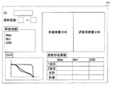
- FIG. 5 is a conceptual diagram showing a screen for displaying the actual dose distribution
- FIG. 6 is a conceptual diagram showing the dose to be optimized
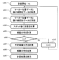
- FIG. These are the flowcharts which show the process sequence of a proton beam dose evaluation system.
- the present invention can be applied to particle beam irradiation systems such as proton beam irradiation systems and carbon beam irradiation systems, particle beam dose evaluation systems such as proton beam dose evaluation systems and carbon beam dose evaluation systems, and treatment planning apparatuses. .
- particle beam irradiation systems such as proton beam irradiation systems and carbon beam irradiation systems
- particle beam dose evaluation systems such as proton beam dose evaluation systems and carbon beam dose evaluation systems
- treatment planning apparatuses treatment planning apparatuses.
- a proton beam irradiation system and a proton beam dose evaluation system will be described as an example with reference to FIG.
- a proton beam irradiation system includes a proton beam generator 10, a beam transport system 20, an irradiation nozzle 22, a moving body tracking device 35, a couch 27, and a proton beam irradiation control device. 40, a proton beam dose calculation device 45 is provided.
- a proton beam irradiation apparatus for irradiating a target with a proton beam includes a proton beam generator 10, a beam transport system 20, and an irradiation nozzle 22.
- the proton beam generator 10 includes an ion source 12, a linac 13, and a synchrotron 11.
- the synchrotron 11 includes a deflection electromagnet 14, a quadrupole electromagnet (not shown), a high frequency accelerator 18, a high frequency output device 19, an output deflector 17, and the like.
- the ion source 12 is connected to the linac 13, and the linac 13 is connected to the synchrotron 11.
- the proton beam generated from the ion source 12 is accelerated in the previous stage by the linac 13 and enters the synchrotron 11.
- the proton beam further accelerated by the synchrotron 11 is emitted to the beam transport system 20.
- the beam transport system 20 includes a plurality of deflecting electromagnets 21 and quadrupole electromagnets (not shown), and is connected to the synchrotron 11 and the irradiation nozzle 22. Further, a part of the beam transport system 20 and the irradiation nozzle 22 are installed in a cylindrical gantry 25 and can rotate together with the gantry 25. The proton beam emitted from the synchrotron 11 is converged by the quadrupole electromagnet while passing through the beam transport system 20, and the direction is changed by the deflecting electromagnet 21 to enter the irradiation nozzle 22.
- the irradiation nozzle 22 includes two pairs of scanning electromagnets, a dose monitor 22B, and a position monitor 22A.
- the two pairs of scanning electromagnets are installed in directions orthogonal to each other, and can deflect the proton beam so that the proton beam reaches a desired position in a plane perpendicular to the beam axis at the target position.
- the dose monitor 22 ⁇ / b> B is a monitor that measures the irradiation amount of the proton beam irradiated to the target, and outputs the detected measurement value to the proton beam irradiation control device 40.
- the position monitor 22A is a monitor for indirectly measuring the irradiation position of the proton beam irradiated to the target by detecting the position through which the proton beam irradiated to the target has passed, and the detected value is used as the proton beam. Output to the irradiation controller 40.
- the proton beam that has passed through the irradiation nozzle 22 reaches the target in the irradiation object 26.
- the irradiation object 26 represents a patient and a target represents a tumor etc.
- the bed on which the irradiation object 26 is placed is called a couch 27.
- the couch 27 can move in directions of three orthogonal axes based on an instruction from the proton beam irradiation control device 40, and can further rotate about each axis. By these movement and rotation, the position of the irradiation object 26 can be moved to a desired position.
- the proton beam irradiation control device 40 is connected to the proton beam generation device 10, the beam transport system 20, the irradiation nozzle 22, the moving body tracking control device 41, the couch 27, the storage device 42, the console 43, the proton beam dose calculation device 45, and the like. And controls the proton beam generator 10, the beam transport system 20, the irradiation nozzle 22, and the like.
- the proton beam irradiation control device 40 measures the proton beam irradiation amount with the dose monitor 22B, associates the time when the proton beam irradiation position is measured with the position monitor 22A, and proton beam irradiation data as shown in FIG. As an irradiation time recording unit 40A.
- the moving body tracking device 35 includes an imaging X-ray generation device 23A and an X-ray measurement device 24A that capture an image of a marker (tracking target) 29 in the irradiation target 26, and an imaging X-ray generation device 23B and an X-ray measurement device. 24B and two pairs of X-ray imaging devices and a moving body tracking control device 41.
- the tracking target position measurement unit includes imaging X-ray generators 23A and 23B and X-ray measuring devices 24A and 24B that measure the position of the marker 29 during irradiation with the proton beam.
- the two sets of the imaging X-ray generator 23A and the X-ray measuring device 24A and the imaging X-ray generator 23B and the X-ray measuring device 24B are installed so that their X-ray paths intersect each other.
- the two pairs of imaging X-ray generators 23A and 23B and the X-ray measuring devices 24A and 24B are preferably installed in directions orthogonal to each other, but may not be orthogonal to each other.
- the imaging X-ray generators 23A and 23B and the X-ray measuring devices 24A and 24B are not necessarily arranged inside the gantry 25, and may be arranged at fixed places such as a ceiling and a floor. good.
- the moving body tracking control device 41 calculates the position of the marker 29 based on the signal input from the X-ray imaging device, and then determines whether or not to permit the emission of the proton beam based on the position of the marker 29. The determination is made and a signal indicating whether or not proton beam irradiation is possible is transmitted to the proton beam irradiation control device 40.
- the moving body tracking control device 41 has a tracking target time recording unit 41A that records the time (tracking target time) at which X-rays are emitted for each X-ray imaging, and calculates the calculation result of the marker 29 position and the gate signal. The state is recorded as marker position data as shown in FIG.
- the moving body tracking control device 41 emits X-rays generated from the imaging X-ray generation device 23 ⁇ / b> A to the marker 29, and 2 of the X-rays that have passed through the marker 29.
- the marker 29 is imaged by measuring the dimensional dose distribution with the X-ray measuring device 24 ⁇ / b> A, the X-ray generated from the imaging X-ray generator 23 ⁇ / b> B is exposed to the marker 29, and 2 of the X-rays that have passed through the marker 29.
- the marker 29 is imaged by measuring the dimensional dose distribution with the X-ray measuring device 24B.
- the moving body tracking control device 41 calculates the three-dimensional position of the marker 29 embedded in the irradiation target 26 from the two acquired captured images, obtains the target position based on the result, and the obtained target position is determined in advance. It is determined whether or not it is within the specified gate range (irradiation permission range), and when it is determined that the target position is within the gate range, a gate-on signal is transmitted to the proton beam irradiation control device 40. Allow emission. On the other hand, if it is determined that the target position is not within the gate range, a gate-off signal is transmitted and emission is not permitted. In the proton beam irradiation control device 40, the emission of the proton beam is controlled based on the gate-on signal and the gate-off signal generated by the moving object tracking control device 41.
- the specified gate range irradiation permission range
- the acquisition of captured images by the X-ray imaging apparatus is performed at regular intervals of 30 Hz, for example.
- the acquired captured image includes a marker 29 embedded in the body, and the position of the marker 29 in the irradiation target 26 is specified by template matching with a template image of the marker 29 prepared in advance. Since searching for the entire range of the captured image requires time, the position of the marker 29 is searched only within a predetermined size range centered on the position of the marker 29 in the previous captured image.
- FIG. 4 the position of the marker 29 detected by template matching on the X-ray measuring device 24 ⁇ / b> A and the imaging X-ray generator 23 ⁇ / b> A and the position of the marker 29 on the X-ray measuring device 24 ⁇ / b> B and the generation of imaging X-rays.
- a line 28B connecting the device 23B is shown.
- the two lines 28A and 28B ideally intersect at one point, and the intersection is the position where the marker 29 exists.
- the two lines 28A and 28B are usually in a twisted relationship without crossing each other due to the effects of template matching accuracy and installation errors of the X-ray imaging apparatus.
- a common perpendicular line can be drawn at the position where the two lines 28A and 28B in the twisted relationship are closest to each other. This common perpendicular is called a common perpendicular. The midpoint of this common perpendicular is the position of the marker 29.
- the proton beam dose calculation device 45 includes the marker position data recorded by the tracking target time recording unit 41A of the moving object tracking control device 41 and the proton recorded by the irradiation time recording unit 40A of the proton beam irradiation control device 40. It has a synchronization function for specifying the position of the marker 29 when each spot is irradiated from the line irradiation data.
- the dose distribution calculation function that calculates the dose distribution using the target position for each spot synchronized by this synchronization function
- the dose distribution integration function that calculates the actual dose distribution by integrating the dose distribution calculated for each irradiation day
- the proton beam dose calculation device 45 can calculate the dose distribution considering the irradiation results, display information necessary for re-planning on the display unit 45A, and provide it to the operator.
- the screen displayed on the display unit 45A by the dose display function is, for example, a screen as shown in FIG. FIG. 5 shows both the planned dose distribution when the treatment plan is created and the obtained evaluation dose distribution.
- the feature amount calculated by the feature amount calculation function and displayed on the display unit 45A is, for example, a maximum dose or minimum dose in the target, or a dose volume histogram (DVH). For example, a dose for a volume of 99% D99 representing the value.
- an ID for specifying an irradiation target and information on the number of irradiations necessary for these calculations are also displayed on a screen as shown in FIG. 5 and can be set.
- the estimated dose distribution calculation function, and the dose distribution calculation function for evaluation the method of simply calculating the sum of doses and the biological A method of integrating in consideration of the effect is conceivable, and any method can be used.
- LQ model represents the simplest biological effect.
- a and b are constants or values depending on the application of linear energy, and change depending on the cell type.
- d is the daily dose.
- the daily dose value changes, so the daily survival rate value S also changes. Therefore, the dose distribution to be displayed can display the dose when the total cell survival rate is equal and the same amount of proton beam for forming the dose distribution is irradiated every day.
- the dose distribution to be displayed can display the dose when the total cell survival rate is equal and the same amount of proton beam for forming the dose distribution is irradiated every day.
- the proton beam irradiation system of the above-described embodiment employs an irradiation method called a spot scanning method.
- the spot scanning method is a method in which dose distributions formed by thin proton beams are arranged to form a dose distribution that matches the shape of the target.
- Proton rays are characterized by the loss of energy within the body, with the energy loss maximizing immediately before stopping.
- the shape of the dose distribution due to this energy loss is called a Bragg curve and has a peak at the end of the range.
- the depth at which the proton beam forms a peak can be adjusted by changing the energy of the proton beam.
- the dose distribution shape in the direction perpendicular to the beam axis formed by the proton beam is generally a normal distribution.
- the position where the dose distribution in the direction perpendicular to the beam axis is formed can be adjusted by scanning the proton beam with a scanning electromagnet. By combining energy change and scanning with a scanning magnet, a uniform dose distribution can be formed
- the treatment planning device 44 determines the irradiation parameters of the proton beam irradiated to the target.
- the determined irradiation parameters include the gantry angle, energy, irradiation position, and irradiation amount for each spot.
- the treatment planning device 44 can calculate a dose distribution when irradiation is performed with an irradiation parameter of an arbitrary proton beam.
- the treatment planning device 44 determines the dose at which the target is designated.
- the irradiation parameters of the proton beam necessary to form a dose distribution that is covered with the laser beam are optimized.
- the treatment planning device 44 calculates the dose distribution when irradiation is performed with the irradiation parameters obtained as a result of optimization, and presents it to the operator.
- the irradiation parameters are transmitted to the storage device 42 and stored in the storage device 42.
- the treatment planning device 44 performs the optimization (replanning, correction) again of the proton irradiation parameters in the remaining irradiation plans based on the calculated actual dose distribution.
- the difference between the obtained actual dose distribution and the final desired planned dose distribution is defined as a new planned dose distribution, and the remaining dose is optimized.
- the irradiation parameters to be optimized are proton beam energy, irradiation position, and irradiation amount.
- the dose distribution from the first time to the j-th time is calculated to obtain the actual dose distribution, and the difference from the target planned dose distribution is obtained.
- the irradiation parameters are optimized so that the integrated dose from the (j + 1) th time to the Nth time matches the difference.
- the biological effect can be taken into account as a difference, not a simple difference in dose. In that case, it is desirable to optimize the irradiation parameters for the remaining number of irradiations so that the biological effect obtained when irradiation is performed as originally planned is achieved.
- the irradiation parameters for irradiation created by the treatment planning device 44 are stored in the storage device 42, and the proton beam irradiation control device 40 receives necessary information from the storage device 42 before irradiation. To do.
- the irradiation time corresponds to the irradiation time measured for each spot irradiation, the arrival position of the proton beam converted from the measurement result of the position monitor 22A, and the dose monitor 22B.
- the spot dose is recorded as proton beam irradiation data.
- the position of the marker 29 measured by the imaging X-ray generators 23A and 23B and the X-ray measuring devices 24A and 24B, and the position and time of the marker 29 at that time are recorded as marker position data, and are stored in the storage device 42.
- the console 43 is connected to the proton beam irradiation control device 40 and the moving body tracking control device 41, and displays information on the monitor based on signals acquired from the proton beam irradiation control device 40 and the moving body tracking control device 41. In addition, it receives input from an operator who operates the proton beam irradiation system, and transmits various control signals to the proton beam irradiation control device 40 and the moving object tracking control device 41.
- the proton dose evaluation system includes the above-described dose monitor 22B, position monitor 22A, irradiation time recording unit 40A, imaging X-ray generators 23A and 23B, X-ray measuring devices 24A and 24B, tracking target time recording unit 41A, and display unit.
- a proton dose calculation device 45 having 45A and a storage device 42 are included.
- the irradiation object 26 is fixed on the couch 27. Thereafter, the couch 27 is moved to move the irradiation target 26 to a previously planned position. At this time, it is confirmed that the irradiation target 26 has moved to a previously planned position by capturing a captured image using an X-ray imaging apparatus.
- the proton beam irradiation control device 40 reads the irradiation parameters from the storage device 42.
- the operator presses the gantry rotation button from the console 43 to rotate the gantry 25 in accordance with the gantry angle described in the read irradiation parameter.
- the operator presses the X-ray imaging start button from the console 43 to cause the moving object tracking control device 41 to start X-ray exposure and start imaging.
- the X-ray imaging start button is pressed, an X-ray imaging start signal is transmitted to the proton beam irradiation control device 40.
- Template matching is used for tracking the marker 29.
- a position that best matches the pattern of the marker 29 image registered in advance as a template image is searched for on the captured image.
- a position having the maximum matching score on each captured image is detected as a marker 29 and tracked.
- a gate-on signal is transmitted from the moving object tracking control device 41 to the proton beam irradiation control device 40.
- the X-ray imaging in the X-ray imaging apparatus is performed at, for example, 30 Hz.
- the captured time, the position coordinates of the marker 29 calculated by template matching, and the state of the gate signal are recorded as marker position data as shown in FIG. To do.
- one X-ray imaging corresponds to one row of data.
- the time is recorded based on the moment when the X-ray imaging start button is pressed.
- the proton beam irradiation control device 40 accelerates the proton beam to the energy to be irradiated first based on the information read from the storage device 42, the irradiation position, and the irradiation amount. .
- the proton beam irradiation control device 40 controls the ion source 12 and the linac 13 so that the proton beam generated by the ion source 12 is accelerated by the linac 13 and is incident on the synchrotron 11.
- the proton beam irradiation control device 40 controls the synchrotron 11 to accelerate the incident proton beam to the first irradiation energy.
- the proton beam circulating around the synchrotron 11 is accelerated by the high frequency from the high frequency accelerator 18.
- the proton beam irradiation control device 40 controls the excitation amounts of the deflection electromagnet 21 and the quadrupole electromagnet of the beam transport system 20 so that the proton beam of the energy to be irradiated first can reach the irradiation nozzle 22 from the synchrotron 11. Further, the excitation amounts of the two scanning electromagnets in the irradiation nozzle 22 are set so that the proton beam reaches the first irradiation spot position in the irradiation parameters from the storage device 42.
- proton beam irradiation control device 40 receives a gate-on signal from the moving object tracking control device 41, proton beam irradiation is started. If a gate-off signal is received, the process waits until a gate-on signal is received.
- the proton beam irradiation control device 40 After receiving the gate-on signal, the proton beam irradiation control device 40 applies a high frequency to the high frequency emission device 19 and starts emitting the proton beam.
- a high frequency is applied to the high frequency emission device 19
- a part of the proton beam that circulates in the synchrotron 11 passes through the extraction deflector 17, passes through the beam transport system 20, and reaches the irradiation nozzle 22.
- the proton beam that has reached the irradiation nozzle 22 is scanned by two scanning electromagnets, passes through the dose monitor 22B and the position monitor 22A, reaches the target in the irradiation object 26, and forms a dose distribution.
- the irradiation amount for each spot is registered as an irradiation parameter acquired from the storage device 42.
- the proton beam irradiation control device 40 controls the high frequency for emission. Proton beam emission is stopped.
- the proton beam irradiation control device 40 calculates the arrival position of the proton beam at the target position from the position information of the proton beam measured by the position monitor 22A, and agrees with the position registered as the irradiation parameter. Check.
- the proton beam irradiation control device 40 records the proton beam irradiation time, the irradiation position and the irradiation amount as shown in FIG.
- the time when the proton beam is irradiated is the time when the high frequency is applied to the emission high frequency with reference to the time when the proton beam irradiation control device 40 receives the X-ray imaging start signal from the moving body tracking control device 41.
- the irradiation position is a value obtained by converting the position information of the proton beam measured by the position monitor 22A into the arrival position of the proton beam at the target position
- the irradiation amount is a spot dose value obtained from the value measured by the dose monitor 22B. is there.
- the data for one spot corresponds to one line in FIG.
- the proton beam irradiation control device 40 sets the excitation amounts of the two scanning electromagnets so that the proton beam reaches the position registered as the irradiation parameter. If the gate-on signal is continuously received after the setting is completed, the proton beam irradiation control device 40 controls the high frequency for emission and starts emitting the proton beam. If a gate-off signal has been received, the process waits until a gate-on signal is received. When a gate-off signal is received during the irradiation of a certain spot, the proton beam is continuously emitted until the irradiation of the spot being irradiated is completed.
- the proton beam irradiation control device 40 controls the synchrotron 11 to decelerate the proton beam and prepare for the irradiation with the next energy proton beam. Start. As in the case of the first energy, the proton beam irradiation control device 40 controls the ion source 12 and the linac 13 to cause the proton beam to enter the synchrotron 11 and controls the synchrotron 11 to reach the second energy. Accelerate the line.
- the proton beam irradiation control device 40 controls the beam transport system 20 and the two scanning electromagnets to continue the irradiation of the spot, as well as the position information of the proton beam measured by the position monitor 22A and the irradiation measured by the dose monitor 22B. Record the dose and time of irradiation.
- an irradiation completion signal is transmitted from the proton beam irradiation control device 40 to the moving object tracking control device 41.
- the moving body tracking control device 41 controls the imaging X-ray generators 23A and 23B to stop X-ray imaging.
- the operator presses the irradiation preparation button and repeats the proton beam irradiation in the same manner.
- the marker position data created in the moving object tracking control device 41 and the proton beam irradiation data created in the proton beam irradiation control device 40 are output to the storage device 42 and stored.
- the above irradiation process is repeated once a day for N days.
- step S102 the proton beam dose calculation device 45 acquires marker position data and proton beam irradiation data from the storage device.
- step S ⁇ b> 103 the proton beam dose calculation device 45 synchronizes the marker position data and the proton beam irradiation data acquired from the storage device 42 by the synchronization function of the proton beam dose calculation device 45.
- the times recorded in the respective data are based on the timing at which the X-ray imaging start button is pressed, so that the respective times can be synchronized. Therefore, the position of the marker 29 at the moment when each spot is irradiated is obtained based on the recorded time.
- the marker position data is recorded every 33 ms when X-ray imaging is performed at 30 Hz.
- the position of the marker 29 at the moment when each spot is irradiated can be the marker position data with the closest time, or can be interpolated from the two marker position data with the time before and after.
- the proton beam dose calculation device 45 calculates the irradiation position taking the error into consideration in step S104.
- the proton beam dose calculation device 45 calculates the dose distribution in consideration of the influence of the target movement as a spot position error.
- the target position at the time of spot irradiation calculated in the previous step S103 is projected onto a plane including an isocenter perpendicular to the beam axis of the proton beam that varies depending on the angle of the gantry 25, and the X and Y directions in the plane are projected. Find the coordinates.
- the X direction and the Y direction coincide with the directions in which the two pairs of scanning electromagnets respectively scan.
- the dose distribution is calculated assuming that the position of the proton beam has moved by -L in the X direction.
- the influence of the non-rigid movement of the target in the body is negligible in the case of gate irradiation, so it is ignored.
- the spatial position irradiated with the proton beam is recorded as proton beam irradiation data for each spot.
- the X coordinate of the spot recorded in the proton beam irradiation data is Xs
- the X coordinate of the spot is set to Xs-L, which is the irradiation position for dose calculation.
- the same process is repeated for the Y direction.
- the depth direction is calculated using the proton beam energy setting value stored in the treatment planning device 44.
- the dose calculation dose is a value recorded in the proton beam irradiation data.
- step S105 the proton beam dose calculation device 45 calculates the dose distribution by the dose distribution calculation function using the dose calculation irradiation position and the dose calculation dose obtained in the previous step S104. In the case of irradiation from a plurality of gantry angles, the dose distribution for all gantry angles is calculated.
- step S106 the proton dose calculation device 45 determines whether or not the dose distribution calculation up to the j-th time has been completed. When it is determined that the process is completed, the process proceeds to step S107. When it is determined that there is a remaining part, the process returns to step S102 via step S110, and the dose distribution calculation for the next irradiation is performed.
- the present invention is a system suitably used for adaptive particle beam therapy in which a dose distribution is evaluated in the middle of a series of irradiations and re-planning is performed, and the actual dose distribution is obtained by integrating all irradiated dose distributions. However, it is not the final dose distribution. Therefore, it is easier to determine whether the desired dose distribution can be obtained by predicting and adding the dose distributions that have not yet been irradiated. Calculate the expected dose distribution from the treatment plan. It is hoped that.
- the proton beam dose calculation device 45 calculates the predicted dose distribution from the (j + 1) th time to the Nth time in step S107.
- the predicted dose distribution may be a dose distribution at the time of planning, or may be obtained by normalizing the accumulated result distribution to a daily amount.
- the dose distribution from the (j + 1) th time to the Nth time can be regarded as the same and can be calculated.
- step S108 the proton beam dose calculation device 45 adds the dose distributions obtained up to the j-th time obtained in the previous steps S102 to S106 by the dose distribution integration function of the proton beam dose calculation device 45 to obtain the actual dose distribution.
- the evaluation dose distribution is created by adding up the obtained actual dose distribution and the predicted dose distribution.
- step S109 the proton dose calculation device 45 obtains the characteristic amount of the obtained evaluation dose distribution by the dose display function of the proton beam dose calculation device 45, and the evaluation dose distribution or feature is displayed on the display unit 45A.
- the amount is displayed as a screen as shown in FIG. 5 together with the planned dose distribution and the like.
- the operator confirms the dose distribution for evaluation and the feature amount displayed on the display unit 45A, determines whether or not the irradiation so far is as planned, and determines whether or not re-planning is necessary.
- the operator inputs an input unit (not shown) of the console 43, an input unit (not shown) of the treatment planning device 44, and an input unit (not shown) of the proton dose calculation device 45 (not shown).
- the recalculation is instructed using (not shown).
- the treatment planning device 44 receives the data of the actual dose distribution from the proton beam dose calculation device 45 and re-adjusts the treatment plan so as to obtain a desired dose distribution.
- the particle beam dose evaluation system, the planning apparatus, the particle beam irradiation system, and the dose evaluation method described above have a function / process for recording marker position data and proton beam irradiation data.
- the marker position data includes position information of the marker 29 measured for moving body tracking irradiation and information on the time when X-ray imaging was performed.
- the proton beam irradiation data includes information on the time of irradiation of each spot, the actual irradiation position, and the actual irradiation amount.
- the marker position data and the proton beam irradiation data are synchronized, and the actual dose distribution of the proton beam irradiation is calculated using the marker position data and the proton beam irradiation data at the time of spot irradiation.
- the present embodiment it is possible to examine whether or not the re-planning is performed based on the actual dose distribution reflecting the information during irradiation and the details thereof. That is, it is possible to make a re-planning decision in consideration of the influence of the interaction effect, and it is possible to make a more appropriate decision than in the past.
- the proton beam dose calculation device 45 can calculate the dose distribution that more accurately reflects the actual irradiation result by calculating the actual dose distribution in consideration of biological effects when calculating the actual dose distribution. It is possible to support making a more appropriate judgment.
- the proton beam dose calculation device 45 can more easily determine whether or not the desired dose distribution planned can be obtained by calculating the planned dose distribution to be irradiated by the treatment plan. It becomes possible to make more appropriate judgments.
- the proton beam dose calculation device 45 has a display unit 45A that displays at least one of the actual dose distribution, the planned dose distribution, or the evaluation dose distribution obtained by adding the actual dose distribution and the planned dose distribution. Therefore, since judgment based on vision can be performed, judgment can be made more accurately.
- the proton beam dose calculation device 45 obtains a feature amount of the dose distribution from the evaluation dose distribution, and also displays the feature amount on the display unit 45A, thereby providing more judgment materials for making a re-planning judgment. Can contribute to making a more appropriate decision.
- a treatment planning apparatus 44 having a particle beam dose evaluation system for creating a proton beam treatment plan, wherein the proton dose calculation apparatus 45 outputs the calculated actual dose distribution to the treatment planning apparatus 44,
- the treatment planning device 44 corrects the proton beam treatment plan so as to obtain a desired dose distribution based on the input actual dose distribution, thereby generating a new planned dose distribution considering the influence of the interaction effect. And more effective proton beam irradiation can be performed.
- the particle beam irradiation system determines whether or not the target position is within a range designated in advance based on the positions of the markers 29 measured by the imaging X-ray generators 23A and 23B and the X-ray measuring devices 24A and 24B.
- a moving body tracking control device 41 that outputs a signal permitting the emission of the proton beam to the proton beam irradiation control device 40 when determined to be within the range, the proton beam irradiation control device 40 includes: By controlling the proton beam based on the signal generated by the moving body tracking control device 41, the irradiation accuracy of the proton beam on the moving target can be further improved, and the effect of the proton beam irradiation can be further enhanced.
- the dose distribution is integrated and the gate irradiation is determined using only the planning X-ray CT image captured before a series of irradiations.
- Accumulation of dose distribution and determination of gate irradiation can be performed by appropriately using a CT image (CBCT image) and an X-ray CT image captured during proton irradiation for treatment.
- an X-ray CBCT image can be obtained by imaging an X-ray image while rotating the gantry 25. Since such imaging can be performed immediately before or after irradiation, a CT image closest to the state of the target at the time of irradiation can be obtained.
- the value of a pixel called a CT value of a CT image is important because it is related to the composition of the substance. It is known that a CBCT image has a lower CT value accuracy than a normal CT image due to the limitation of its configuration. Therefore, by making a deformation called non-rigid registration according to the planning X-ray CT image in accordance with the CBCT image, a more accurate dose distribution can be calculated, and a more appropriate re-planning decision can be made. .
- the calculation result of the dose distribution is calculated according to the CBCT system.
- the finally displayed dose distribution needs to be one, it matches the system of the planning X-ray CT image. It is desirable to deform again by non-rigid registration.
- the moving object tracking control device 41 is directed to the proton beam irradiation control device 40 with reference to the moment when the X-ray imaging start button is pressed.
- the gantry 25 transmits a rotation completion signal to the moving object tracking control device 41 and the proton beam irradiation control device 40 at the moment when the gantry rotation is completed instead of the X-ray imaging start signal, and the other is used as a reference.
- Timing and signals can be used as a reference.
- a time recording device can be provided outside, and a timing signal can be received and recorded from both the moving body tracking control device 41 and the proton beam irradiation control device 40.
- the tracking target time recording unit 41A is provided in the moving object tracking control device 41 and the irradiation time recording unit 40A is provided in the proton beam irradiation control device 40 has been described.
- the unit may be provided in the proton beam dose calculation device 45.
- each calculation function in the particle beam dose evaluation system is provided in the proton beam dose calculation device 45 and is independent of the treatment planning device 44 .
- Each calculation function of the evaluation system may be integrated with the treatment planning apparatus 44.
- the treatment planning apparatus provided with each calculation function of the proton beam dose evaluation system described in this embodiment is used as the particle beam dose evaluation system. Is also possible.
- synchrotron has been described as an example of the accelerator for accelerating the proton beam, a cyclotron may be used as the accelerator.
- the irradiation method may be tracking irradiation that tracks the irradiation position based on the position of the marker 29 or the like instead of the gate irradiation.
- the orientation of the distribution forming X-ray generator is changed in accordance with the movement of the target, and the X-ray irradiation position is changed in accordance with the movement of the target.
- tracking irradiation can be performed by adjusting the excitation amount of the scanning electromagnet according to the target position.
- the present invention can be similarly applied to a raster scanning method and a line scanning method in which a fine particle beam is irradiated without stopping the particle beam.
- the particle beam to be evaluated is not limited to the proton beam, but can be similarly applied to a heavy particle beam such as a carbon beam.
- the tracking target is the marker 29, and the position of the marker 29 is used as the marker position data.
- the tracking target may be the target itself, and the target position may be used as the data.
- the tracking target may be a high-density region such as a bone that moves in conjunction with a target other than the target, for example, a bone such as a rib in the irradiation target 26, and these positions may be used as position data.
Landscapes
- Health & Medical Sciences (AREA)
- Engineering & Computer Science (AREA)
- Life Sciences & Earth Sciences (AREA)
- Biomedical Technology (AREA)
- Veterinary Medicine (AREA)
- Public Health (AREA)
- General Health & Medical Sciences (AREA)
- Nuclear Medicine, Radiotherapy & Molecular Imaging (AREA)
- Animal Behavior & Ethology (AREA)
- Pathology (AREA)
- Radiology & Medical Imaging (AREA)
- Medical Informatics (AREA)
- Physics & Mathematics (AREA)
- High Energy & Nuclear Physics (AREA)
- Molecular Biology (AREA)
- Biophysics (AREA)
- Optics & Photonics (AREA)
- Surgery (AREA)
- Heart & Thoracic Surgery (AREA)
- Pulmonology (AREA)
- Theoretical Computer Science (AREA)
- General Physics & Mathematics (AREA)
- Spectroscopy & Molecular Physics (AREA)
- General Engineering & Computer Science (AREA)
- Radiation-Therapy Devices (AREA)
- Measurement Of Radiation (AREA)
Priority Applications (2)
| Application Number | Priority Date | Filing Date | Title |
|---|---|---|---|
| US16/089,410 US10835764B2 (en) | 2016-03-30 | 2017-03-23 | Dose evaluation system, planning system, particle irradiation system and dose evaluation method |
| CN201780021050.XA CN108883303B (zh) | 2016-03-30 | 2017-03-23 | 粒子束剂量评价系统、计划装置及粒子束照射系统 |
Applications Claiming Priority (2)
| Application Number | Priority Date | Filing Date | Title |
|---|---|---|---|
| JP2016069463A JP6757583B2 (ja) | 2016-03-30 | 2016-03-30 | 粒子線線量評価システム、計画装置および粒子線照射システムならびに線量評価方法 |
| JP2016-069463 | 2016-03-30 |
Publications (1)
| Publication Number | Publication Date |
|---|---|
| WO2017170178A1 true WO2017170178A1 (ja) | 2017-10-05 |
Family
ID=59965586
Family Applications (1)
| Application Number | Title | Priority Date | Filing Date |
|---|---|---|---|
| PCT/JP2017/011866 Ceased WO2017170178A1 (ja) | 2016-03-30 | 2017-03-23 | 粒子線線量評価システム、計画装置および粒子線照射システムならびに線量評価方法 |
Country Status (4)
| Country | Link |
|---|---|
| US (1) | US10835764B2 (https=) |
| JP (1) | JP6757583B2 (https=) |
| CN (1) | CN108883303B (https=) |
| WO (1) | WO2017170178A1 (https=) |
Cited By (5)
| Publication number | Priority date | Publication date | Assignee | Title |
|---|---|---|---|---|
| CN111867227A (zh) * | 2020-07-22 | 2020-10-30 | 中国科学院近代物理研究所 | 核孔膜生产终端束斑自动校准调束装置 |
| US20210393985A1 (en) * | 2018-12-25 | 2021-12-23 | Hitachi, Ltd. | Particle therapy system, dose distribution evaluation system, and method for operating particle therapy system |
| WO2022158047A1 (ja) * | 2021-01-20 | 2022-07-28 | 株式会社日立製作所 | 判断支援システム、放射線治療システム及び判断支援システムにおける判断支援方法 |
| CN116165692A (zh) * | 2022-12-12 | 2023-05-26 | 中国科学院近代物理研究所 | 一种束流剂量及位置分布监测系统及使用方法 |
| WO2023210183A1 (ja) * | 2022-04-25 | 2023-11-02 | 株式会社日立製作所 | 治療計画評価システム、治療計画評価方法および治療計画評価システムを備える放射線治療システム |
Families Citing this family (8)
| Publication number | Priority date | Publication date | Assignee | Title |
|---|---|---|---|---|
| KR102209585B1 (ko) * | 2019-02-12 | 2021-01-29 | 재단법인 아산사회복지재단 | 3차원 선량 분포 측정 시스템 및 방법 |
| CN111973892B (zh) * | 2019-05-23 | 2022-07-08 | 千才生医股份有限公司 | 用于放射治疗的笔尖式质子束扫描系统剂量分布重建方法 |
| JP7430044B2 (ja) * | 2019-09-17 | 2024-02-09 | 住友重機械工業株式会社 | 放射線治療装置 |
| JP2021121273A (ja) * | 2020-01-31 | 2021-08-26 | 株式会社日立製作所 | 治療計画装置、粒子線治療システム及びコンピュータプログラム |
| WO2021240713A1 (ja) * | 2020-05-28 | 2021-12-02 | イーグロース株式会社 | 放射線治療用支援装置とプログラム |
| CN113797447A (zh) * | 2020-06-11 | 2021-12-17 | 中硼(厦门)医疗器械有限公司 | 放射治疗系统及其治疗计划生成方法 |
| CN113797448B (zh) * | 2020-06-11 | 2024-08-13 | 中硼(厦门)医疗器械有限公司 | 照射参数选取装置及其使用方法 |
| JP7692282B2 (ja) * | 2021-04-21 | 2025-06-13 | 株式会社日立ハイテク | 治療計画装置、粒子線治療システム、治療計画生成方法及びコンピュータプログラム |
Citations (6)
| Publication number | Priority date | Publication date | Assignee | Title |
|---|---|---|---|---|
| JP2006223425A (ja) * | 2005-02-16 | 2006-08-31 | Hokkaido Univ | 放射線治療効果予測方法およびプログラム |
| US20110087090A1 (en) * | 2008-06-25 | 2011-04-14 | Koninklijke Philips Electronics N.V. | Radiation therapy system with real time magnetic resonance monitoring |
| JP2012210232A (ja) * | 2009-08-19 | 2012-11-01 | Mitsubishi Electric Corp | 放射線治療システム |
| JP2014054302A (ja) * | 2012-09-11 | 2014-03-27 | Hitachi Ltd | 動体追跡装置および放射線治療システム |
| JP2015500053A (ja) * | 2011-11-30 | 2015-01-05 | コーニンクレッカ フィリップス エヌ ヴェ | 適応的治療計画のためのビームセグメントレベル線量計算及び時間的動き追跡 |
| JP2015029793A (ja) * | 2013-08-05 | 2015-02-16 | 株式会社日立製作所 | 放射線治療システム |
Family Cites Families (7)
| Publication number | Priority date | Publication date | Assignee | Title |
|---|---|---|---|---|
| JPS5224421B1 (https=) | 1970-02-27 | 1977-07-01 | ||
| JP3053389B1 (ja) | 1998-12-03 | 2000-06-19 | 三菱電機株式会社 | 動体追跡照射装置 |
| CN101015723B (zh) * | 2006-02-09 | 2010-04-07 | 吴大怡 | 机器人放射治疗系统 |
| WO2009072618A1 (ja) * | 2007-12-07 | 2009-06-11 | Mitsubishi Heavy Industries, Ltd. | 放射線治療計画装置および放射線治療計画方法 |
| US20120150017A1 (en) | 2009-03-12 | 2012-06-14 | National Institute Of Radiological Sciences | Open pet/mri hybrid machine |
| JP5484036B2 (ja) * | 2009-12-23 | 2014-05-07 | 三菱電機株式会社 | 粒子線治療装置 |
| JP2014045302A (ja) | 2012-08-27 | 2014-03-13 | Canon Inc | 画像処理装置、画像処理装置の制御方法、及びプログラム |
-
2016
- 2016-03-30 JP JP2016069463A patent/JP6757583B2/ja not_active Expired - Fee Related
-
2017
- 2017-03-23 CN CN201780021050.XA patent/CN108883303B/zh not_active Expired - Fee Related
- 2017-03-23 WO PCT/JP2017/011866 patent/WO2017170178A1/ja not_active Ceased
- 2017-03-23 US US16/089,410 patent/US10835764B2/en active Active
Patent Citations (6)
| Publication number | Priority date | Publication date | Assignee | Title |
|---|---|---|---|---|
| JP2006223425A (ja) * | 2005-02-16 | 2006-08-31 | Hokkaido Univ | 放射線治療効果予測方法およびプログラム |
| US20110087090A1 (en) * | 2008-06-25 | 2011-04-14 | Koninklijke Philips Electronics N.V. | Radiation therapy system with real time magnetic resonance monitoring |
| JP2012210232A (ja) * | 2009-08-19 | 2012-11-01 | Mitsubishi Electric Corp | 放射線治療システム |
| JP2015500053A (ja) * | 2011-11-30 | 2015-01-05 | コーニンクレッカ フィリップス エヌ ヴェ | 適応的治療計画のためのビームセグメントレベル線量計算及び時間的動き追跡 |
| JP2014054302A (ja) * | 2012-09-11 | 2014-03-27 | Hitachi Ltd | 動体追跡装置および放射線治療システム |
| JP2015029793A (ja) * | 2013-08-05 | 2015-02-16 | 株式会社日立製作所 | 放射線治療システム |
Cited By (8)
| Publication number | Priority date | Publication date | Assignee | Title |
|---|---|---|---|---|
| US20210393985A1 (en) * | 2018-12-25 | 2021-12-23 | Hitachi, Ltd. | Particle therapy system, dose distribution evaluation system, and method for operating particle therapy system |
| US11904185B2 (en) * | 2018-12-25 | 2024-02-20 | Hitachi, Ltd. | Particle therapy system, dose distribution evaluation system, and method for operating particle therapy system |
| CN111867227A (zh) * | 2020-07-22 | 2020-10-30 | 中国科学院近代物理研究所 | 核孔膜生产终端束斑自动校准调束装置 |
| WO2022158047A1 (ja) * | 2021-01-20 | 2022-07-28 | 株式会社日立製作所 | 判断支援システム、放射線治療システム及び判断支援システムにおける判断支援方法 |
| JP2022111774A (ja) * | 2021-01-20 | 2022-08-01 | 株式会社日立製作所 | 判断支援システム、放射線治療システム及び判断支援システムにおける判断支援方法 |
| JP7553366B2 (ja) | 2021-01-20 | 2024-09-18 | 株式会社日立ハイテク | 判断支援システム、放射線治療システム及び判断支援システムにおける判断支援方法 |
| WO2023210183A1 (ja) * | 2022-04-25 | 2023-11-02 | 株式会社日立製作所 | 治療計画評価システム、治療計画評価方法および治療計画評価システムを備える放射線治療システム |
| CN116165692A (zh) * | 2022-12-12 | 2023-05-26 | 中国科学院近代物理研究所 | 一种束流剂量及位置分布监测系统及使用方法 |
Also Published As
| Publication number | Publication date |
|---|---|
| JP6757583B2 (ja) | 2020-09-23 |
| JP2017176533A (ja) | 2017-10-05 |
| CN108883303A (zh) | 2018-11-23 |
| CN108883303B (zh) | 2021-04-30 |
| US10835764B2 (en) | 2020-11-17 |
| US20200054897A1 (en) | 2020-02-20 |
Similar Documents
| Publication | Publication Date | Title |
|---|---|---|
| JP6757583B2 (ja) | 粒子線線量評価システム、計画装置および粒子線照射システムならびに線量評価方法 | |
| JP5722559B2 (ja) | 治療計画装置 | |
| JP6742153B2 (ja) | 放射線照射システムおよび動体追跡装置 | |
| US9873003B2 (en) | X-ray positioning apparatus, X-ray positioning method, and attentional image photographing method | |
| JP6744123B2 (ja) | 動体追跡装置および放射線照射システム | |
| US11904185B2 (en) | Particle therapy system, dose distribution evaluation system, and method for operating particle therapy system | |
| WO2019077936A1 (ja) | 放射線治療装置 | |
| JP2016144573A (ja) | 画像処理装置および粒子線治療装置 | |
| JP2008022896A (ja) | 位置決め装置 | |
| US11282244B2 (en) | Moving body tracking apparatus, radiation therapy system including the same, program, and moving body tracking method | |
| WO2017188079A1 (ja) | 追跡対象認識シミュレータ、若しくはマーカ認識シミュレータおよび動体追跡装置ならびに放射線照射システム | |
| JP6727644B2 (ja) | 動体追跡装置および放射線照射システム | |
| JP6063983B2 (ja) | 粒子線治療システム | |
| JP2015110171A (ja) | 粒子線治療システム |
Legal Events
| Date | Code | Title | Description |
|---|---|---|---|
| DPE1 | Request for preliminary examination filed after expiration of 19th month from priority date (pct application filed from 20040101) | ||
| NENP | Non-entry into the national phase |
Ref country code: DE |
|
| 121 | Ep: the epo has been informed by wipo that ep was designated in this application |
Ref document number: 17774715 Country of ref document: EP Kind code of ref document: A1 |
|
| 122 | Ep: pct application non-entry in european phase |
Ref document number: 17774715 Country of ref document: EP Kind code of ref document: A1 |