WO2017169694A1 - エンジン用カムシャフトおよびその製造方法 - Google Patents
エンジン用カムシャフトおよびその製造方法 Download PDFInfo
- Publication number
- WO2017169694A1 WO2017169694A1 PCT/JP2017/009983 JP2017009983W WO2017169694A1 WO 2017169694 A1 WO2017169694 A1 WO 2017169694A1 JP 2017009983 W JP2017009983 W JP 2017009983W WO 2017169694 A1 WO2017169694 A1 WO 2017169694A1
- Authority
- WO
- WIPO (PCT)
- Prior art keywords
- hole
- camshaft
- shaft portion
- shaft
- cam
- Prior art date
- Legal status (The legal status is an assumption and is not a legal conclusion. Google has not performed a legal analysis and makes no representation as to the accuracy of the status listed.)
- Ceased
Links
Images












Classifications
-
- F—MECHANICAL ENGINEERING; LIGHTING; HEATING; WEAPONS; BLASTING
- F01—MACHINES OR ENGINES IN GENERAL; ENGINE PLANTS IN GENERAL; STEAM ENGINES
- F01L—CYCLICALLY OPERATING VALVES FOR MACHINES OR ENGINES
- F01L1/00—Valve-gear or valve arrangements, e.g. lift-valve gear
- F01L1/02—Valve drive
- F01L1/04—Valve drive by means of cams, camshafts, cam discs, eccentrics or the like
- F01L1/047—Camshafts
-
- B—PERFORMING OPERATIONS; TRANSPORTING
- B22—CASTING; POWDER METALLURGY
- B22C—FOUNDRY MOULDING
- B22C7/00—Patterns; Manufacture thereof so far as not provided for in other classes
-
- B—PERFORMING OPERATIONS; TRANSPORTING
- B22—CASTING; POWDER METALLURGY
- B22C—FOUNDRY MOULDING
- B22C9/00—Moulds or cores; Moulding processes
- B22C9/02—Sand moulds or like moulds for shaped castings
-
- B—PERFORMING OPERATIONS; TRANSPORTING
- B22—CASTING; POWDER METALLURGY
- B22C—FOUNDRY MOULDING
- B22C9/00—Moulds or cores; Moulding processes
- B22C9/22—Moulds for peculiarly-shaped castings
-
- B—PERFORMING OPERATIONS; TRANSPORTING
- B22—CASTING; POWDER METALLURGY
- B22D—CASTING OF METALS; CASTING OF OTHER SUBSTANCES BY THE SAME PROCESSES OR DEVICES
- B22D25/00—Special casting characterised by the nature of the product
- B22D25/02—Special casting characterised by the nature of the product by its peculiarity of shape; of works of art
-
- F—MECHANICAL ENGINEERING; LIGHTING; HEATING; WEAPONS; BLASTING
- F01—MACHINES OR ENGINES IN GENERAL; ENGINE PLANTS IN GENERAL; STEAM ENGINES
- F01L—CYCLICALLY OPERATING VALVES FOR MACHINES OR ENGINES
- F01L1/00—Valve-gear or valve arrangements, e.g. lift-valve gear
- F01L1/02—Valve drive
- F01L1/04—Valve drive by means of cams, camshafts, cam discs, eccentrics or the like
-
- F—MECHANICAL ENGINEERING; LIGHTING; HEATING; WEAPONS; BLASTING
- F16—ENGINEERING ELEMENTS AND UNITS; GENERAL MEASURES FOR PRODUCING AND MAINTAINING EFFECTIVE FUNCTIONING OF MACHINES OR INSTALLATIONS; THERMAL INSULATION IN GENERAL
- F16C—SHAFTS; FLEXIBLE SHAFTS; ELEMENTS OR CRANKSHAFT MECHANISMS; ROTARY BODIES OTHER THAN GEARING ELEMENTS; BEARINGS
- F16C3/00—Shafts; Axles; Cranks; Eccentrics
- F16C3/04—Crankshafts, eccentric-shafts; Cranks, eccentrics
- F16C3/18—Eccentric-shafts
-
- F—MECHANICAL ENGINEERING; LIGHTING; HEATING; WEAPONS; BLASTING
- F16—ENGINEERING ELEMENTS AND UNITS; GENERAL MEASURES FOR PRODUCING AND MAINTAINING EFFECTIVE FUNCTIONING OF MACHINES OR INSTALLATIONS; THERMAL INSULATION IN GENERAL
- F16H—GEARING
- F16H53/00—Cams or cam-followers, e.g. rollers for gearing mechanisms
- F16H53/02—Single-track cams for single-revolution cycles; Camshafts with such cams
- F16H53/025—Single-track cams for single-revolution cycles; Camshafts with such cams characterised by their construction, e.g. assembling or manufacturing features
-
- F—MECHANICAL ENGINEERING; LIGHTING; HEATING; WEAPONS; BLASTING
- F01—MACHINES OR ENGINES IN GENERAL; ENGINE PLANTS IN GENERAL; STEAM ENGINES
- F01L—CYCLICALLY OPERATING VALVES FOR MACHINES OR ENGINES
- F01L2303/00—Manufacturing of components used in valve arrangements
-
- F—MECHANICAL ENGINEERING; LIGHTING; HEATING; WEAPONS; BLASTING
- F16—ENGINEERING ELEMENTS AND UNITS; GENERAL MEASURES FOR PRODUCING AND MAINTAINING EFFECTIVE FUNCTIONING OF MACHINES OR INSTALLATIONS; THERMAL INSULATION IN GENERAL
- F16C—SHAFTS; FLEXIBLE SHAFTS; ELEMENTS OR CRANKSHAFT MECHANISMS; ROTARY BODIES OTHER THAN GEARING ELEMENTS; BEARINGS
- F16C2220/00—Shaping
- F16C2220/02—Shaping by casting
-
- F—MECHANICAL ENGINEERING; LIGHTING; HEATING; WEAPONS; BLASTING
- F16—ENGINEERING ELEMENTS AND UNITS; GENERAL MEASURES FOR PRODUCING AND MAINTAINING EFFECTIVE FUNCTIONING OF MACHINES OR INSTALLATIONS; THERMAL INSULATION IN GENERAL
- F16C—SHAFTS; FLEXIBLE SHAFTS; ELEMENTS OR CRANKSHAFT MECHANISMS; ROTARY BODIES OTHER THAN GEARING ELEMENTS; BEARINGS
- F16C2360/00—Engines or pumps
- F16C2360/18—Camshafts
Definitions
- the present invention relates to an engine camshaft and a manufacturing method thereof.
- Patent Document 1 discloses an example of a method for manufacturing a hollow type camshaft.
- the camshaft manufacturing method described in Patent Document 1 includes a step of manufacturing a mold by disposing a collapsible core made of sand or the like in a collapsible main die made of sand or the like, A step of pouring the molten metal into a cavity formed between the molten metal and a step of disintegrating and removing the mold after the molten metal is cooled.
- the core is provided with a plurality of positioning pins protruding radially from the outer peripheral surface thereof, and the core is positioned in the main mold by the plurality of pins.
- An object of the present invention is to provide a camshaft for an engine that can be easily manufactured while being lightweight, and a method for manufacturing the camshaft.
- the present invention is a cast engine camshaft comprising a shaft portion and a cam portion provided on the outer periphery of the shaft portion, wherein the shaft portion is opened at a predetermined position on the outer peripheral surface of the shaft portion.
- the hole portion is formed so as to gradually narrow toward the center from the radially outer side of the shaft portion.
- the present invention is a method for manufacturing the engine camshaft described above, wherein the first prototype component corresponding to the one radial side portion of the camshaft and the radial other side portion of the camshaft are provided.
- a step of manufacturing the first sand mold by removing the first prototype component from the solidified cast sand, and placing the second prototype component in the casting frame, and pouring the casting sand into the casting frame.
- the camshaft is cast by combining the step of producing a second sand mold by solidifying and removing the second prototype component from the solidified cast sand, and the first sand mold and the second sand mold.
- Have a cavity A step of producing a mold, a step of cooling the cured pouring molten metal into the cavity by collapsing removing the mold, in which and a step of taking out the camshaft from the mold.
- FIG. 4 is a sectional view of the exhaust camshaft (a sectional view taken along line AA in FIG. 3).
- FIG. 2 is a cross-sectional view of the intake camshaft shown in FIG. 1 along the line BB.
- FIG. 4 is a cross-sectional view of the exhaust camshaft (cross-sectional view taken along line CC in FIG. 3).
- FIG. 4 is a sectional view of the exhaust camshaft (a sectional view taken along the line DD in FIG. 3). It is sectional drawing which shows a mode that the 1st sand type
- FIG. 13 It is sectional drawing which shows the 3rd modification of the hole of an exhaust camshaft. It is sectional drawing of the exhaust camshaft which shows an example of the positional relationship of the hole part shown to FIG. 11A, and the nose part of a cam part. It is sectional drawing of the exhaust camshaft which shows the positional relationship of the 4th modification of the said hole part, and the nose part of a cam part. It is a perspective view of an exhaust camshaft when the shaft portion of the exhaust camshaft is formed in a hexagonal cross section. It is sectional drawing which shows the positional relationship of the prototype (shaft part) of the exhaust camshaft shown by FIG. 13, and a 1st sand mold and a 2nd sand mold. FIG.
- FIG. 6 is a cross-sectional view showing an intake camshaft when a hollow portion is formed in the radial center portion of the shaft portion of the intake camshaft and all the hole portions opened to the outer peripheral surface of the shaft portion communicate with the hollow portion. is there.
- FIG. 16 is a cross-sectional view of the intake camshaft shown in FIG. 15 taken along the line EE.
- FIG. 16 is a cross-sectional view of the intake camshaft shown in FIG. 15 taken along the line FF.
- a hollow portion is formed in the radial center portion of the shaft portion of the intake camshaft, and the hole portion formed in a section between both end portions of the shaft portion and the cam portion closest to the end portion communicates with the hollow portion. It is sectional drawing which shows the intake camshaft in the case of doing.
- FIG. 18 is a sectional view of the intake camshaft shown in FIG. 17 taken along the line GG.
- An engine including a camshaft according to an embodiment of the present invention is an in-line four-cylinder four-cycle diesel engine, and is assembled on a cylinder block (not shown) and the cylinder block as shown in FIG. And a cylinder head 72.
- a first cylinder, a second cylinder, a third cylinder, and a fourth cylinder are arranged in order from the left side.
- the cylinder head 72 has, for each cylinder, two exhaust ports and two intake ports communicating with the combustion chamber, an exhaust valve for shutting off each exhaust port from the combustion chamber, and shutting each intake port from the combustion chamber.
- An exhaust valve drive mechanism 78 for driving each exhaust valve to open and close each exhaust port at a predetermined timing, and each intake valve for driving each intake valve.
- An intake valve drive mechanism 73 that opens and closes the intake port at a predetermined timing, four bearing portions 24 to 27 that rotatably support an exhaust camshaft 2 described later, and 4 that rotatably supports an intake camshaft 3 described later.
- Two bearing portions 74 to 77 are provided.
- the exhaust valve drive mechanism 78 includes the exhaust camshaft 2, and the intake valve drive mechanism 73 includes the intake camshaft 3.
- the exhaust camshaft 2 and the intake camshaft 3 are connected to the crankshaft via a well-known power transmission mechanism including a chain and a sprocket.
- the exhaust valve driving mechanism 78 includes a return spring (not shown) that biases the exhaust valve in the closing direction
- the intake valve driving mechanism 73 has a return spring (not shown) that biases the intake valve in the closing direction. I have.
- the exhaust camshaft 2 and the intake camshaft 3 respectively open the exhaust valve and the intake valve against the urging force of the return spring by the driving force of the crankshaft.
- the exhaust camshaft 2 and the intake camshaft 3 correspond to the “engine camshaft” of the present invention.
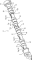
- the exhaust camshaft 2 includes a columnar shaft portion 5 extending in the cylinder row direction, and eight cam portions integrally provided on the outer periphery of the shaft portion 5 (see FIG. 1).
- the first cam portion 6 and the second cam portion 7 are eccentric cams provided corresponding to the first cylinders, and these are adjacent to each other via the journal portion 20. (See FIGS. 2 to 4).
- the first cam portion 6, the second cam portion 7, and the journal portion 20 are located above the first cylinder and on the exhaust side.
- the third cam portion 8 and the fourth cam portion 9 are eccentric cams provided corresponding to the second cylinder, respectively, and are adjacent to each other via the journal portion 21.
- the third cam portion 8, the fourth cam portion 9, and the journal portion 21 are located above the second cylinder and on the exhaust side.
- Each of the fifth cam portion 10 and the sixth cam portion 11 is an eccentric cam provided corresponding to the third cylinder, and these are adjacent to each other via the journal portion 22.
- the fifth cam portion 10, the sixth cam portion 11, and the journal portion 22 are located above the third cylinder and on the exhaust side.
- Each of the seventh cam portion 12 and the eighth cam portion 13 is an eccentric cam provided corresponding to the fourth cylinder, and these are adjacent to each other via the journal portion 23.
- the seventh cam portion 12, the eighth cam portion 13, and the journal portion 23 are located above the fourth cylinder and on the exhaust side.
- Each of the cam portions 6 to 13 includes one nose portion 6a to 13a (see FIG. 2) that protrudes radially outward from the base circle.
- the explosion order of each cylinder is set as follows: first cylinder ⁇ third cylinder ⁇ fourth cylinder ⁇ second cylinder, and accordingly, the cam portions 6 to 13 of the exhaust camshaft 2. Are provided with a phase difference from each other so that the exhaust valves are opened in the order of explosion described above every 90 ° rotation of the exhaust camshaft 2 (see FIG. 2).
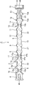
- the shaft portion 5 of the exhaust camshaft 2 corresponds to a section between the sprocket mounting section 4 and the first cam section 6 (corresponding to a “first section” of the present invention. It corresponds to a section between the hole 16 located in the second cam section 7 and the third cam section 8 (sometimes referred to as “the second section” of the present invention).
- Hole 19 and camshaft identification ring located in a section (corresponding to a “second section” of the present invention, which may be referred to as a “second section” in the following description) between the seventh cam portion 12. 14.
- the hole portion 16 has a first hole portion 16 a that opens at a predetermined position on one radial side of the shaft portion 5, and a predetermined position on the other radial side of the shaft portion 5. And a second hole 16b that opens.
- the first hole portion 16a and the second hole portion 16b each extend in the length direction of the shaft portion 5, and are formed so as to gradually narrow toward the center from the radially outer side of the shaft portion 5.
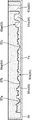
- each of the hole portion 16a and the hole portion 16b is an opening portion that opens in a shape in which a semicircle is combined with both ends of a rectangle extending in the length direction of the shaft portion 5 on the outer peripheral surface of the shaft portion 5.
- the bottom portion 16d has substantially the same depth over the entire length direction, and a boundary portion between the peripheral wall portion 16c and the bottom portion 16d is formed in a curved surface shape.
- the 1st hole part 16a is the same size as the 2nd hole part 16b, and is formed in the same shape in the position symmetrical with the 2nd hole part 16b with respect to the center line of the axis part 5.
- the first hole portion 16a is formed at the apex side of the nose portion 6a of the first cam portion 6, specifically, at the same position as the apex (rotation phase), and the second hole portion 16b
- the cam portion 6 is formed at a position opposite to the nose portion 6a, specifically, at a position that is approximately 180 ° out of phase with the apex of the nose portion 6a.
- the first hole portion 16a and the second hole portion 16b correspond to the “first wall removal portion” of the present invention. In the following description, these holes 16a and 16b may be referred to as “first wall removal portions”.
- the hole portion 17 has a first hole portion 17 a that opens at a predetermined position on one radial side of the shaft portion 5, and a predetermined position on the other radial direction side of the shaft portion 5. And a second hole portion 17b that opens.
- the first hole portion 17a and the second hole portion 17b each extend in the length direction of the shaft portion 5, and are formed so as to gradually narrow from the radially outer side of the shaft portion 5 toward the center. .
- each of the first hole portion 17a and the second hole portion 17b has a shape in which a semicircle is combined with both ends of a rectangle extending in the length direction of the shaft portion 5 on the outer peripheral surface of the shaft portion 5.
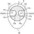
- the opening portion 17e is formed so as to extend in the length direction of the shaft portion 5 with a narrower width than the opening portion 17e and gradually become deeper (approaching the radial center) from both ends in the length direction to the center portion.
- a slope portion 17d having a substantially V-shaped cross section which is formed so as to gradually become shallower from the central portion in the length direction of the shaft portion 5 to both end portions in the length direction, and whose both end portions in the length direction are continuous with the opening portion 17e
- the slope portion 17d has a side wall portion 17c that rises from both ends in the width direction and is continuous with the width direction end portion of the opening 17e.
- the bottom portion of the slope portion 17d (the lower end portion of the V shape) is formed in a curved shape, and the depth of the bottom portion (the depth of the deepest portion of each of the first hole portion 17a and the second hole portion 17b) is It is set to be substantially the same as the depth of the first hole portion 16a and the second hole portion 16b. That is, the diameter (diameter) of the shaft portion 5 in the section between the second cam portion 7 and the third cam portion 8 is the diameter of the shaft portion 5 in the section between the sprocket mounting portion 4 and the first cam portion 6.
- the bottom of the slope portion 17d in the first hole portion 17a and the second hole portion 17b is formed in a curved shape, and stress concentration is unlikely to occur in the bottom portion. For this reason, the strength of the shaft portion 5 in the section between the second cam portion 7 and the third cam portion 8 is greater than the strength of the shaft portion 5 in the section between the sprocket mounting portion 4 and the first cam portion 6. It is getting bigger.
- the first hole 17a is formed in the same shape and the same size as the second hole 17b at a position symmetrical to the second hole 17b with respect to the center line of the shaft portion 5.
- the first hole portion 17 a is formed at a position whose phase is delayed by about 90 ° with respect to the apex of the nose portion 8 a of the third cam portion 8, and the second hole portion 17 b is the nose portion of the third cam portion 8. It is formed at a position where the phase is advanced approximately 90 ° with respect to the vertex of 8a.
- the first hole portion 17a and the second hole portion 17b correspond to the “second wall removal portion” of the present invention. In the following description, these holes 17a and 17b may be referred to as “second thinning portions”.
- the rotation angle adjusting portion 18 is a hexagonal section (regular hexagon) that protrudes radially outward from the outer periphery of the shaft portion 5.
- the rotation angle adjusting unit 18 is used by being engaged with a spanner during engine inspection or the like. That is, at the time of engine inspection or the like, by rotating the spanner by engaging the rotation angle adjusting portion 18 with the opening portion of the spanner, the shaft portion 5 can be rotated and the exhaust port can be closed by the exhaust valve. Thereby, it is possible to prevent foreign matters such as dust from entering from the exhaust port during engine inspection or the like.
- the hole 19 has a first hole 19 a that opens at a predetermined position on one side in the radial direction of the shaft portion 5, and a first hole that opens at a predetermined position on the other side in the radial direction of the shaft portion 5.
- the first hole portion 19a and the second hole portion 19b are formed so as to gradually narrow toward the center from the radially outer side of the shaft portion 5, and more specifically, the hole portion 17a and the hole portion 17b Similarly, it is formed in a substantially V-shaped cross section, but in order to avoid interference with the camshaft identification ring 14, it is formed shorter in the length direction of the shaft portion 5 than the hole portion 17a and the hole portion 17b. .
- the first hole portion 19a is formed at a position where the phase is advanced by approximately 90 ° with respect to the apex of the nose portion 11a (see FIG. 2) of the sixth cam portion 11, and the second hole portion 19b is formed at the sixth cam portion. It is formed at a position where the phase is delayed by approximately 90 ° with respect to the apex of the nose portion 11a of the portion 11.
- the diameter (diameter) of the shaft section 5 in the section between the sixth cam section 11 and the seventh cam section 12 is the sprocket.
- the diameter is set larger than the diameter of the shaft portion 5 in the section between the mounting portion 4 and the first cam portion 6, and the bottoms of the slope portions in the first hole portion 19a and the second hole portion 19b are curved.
- stress concentration is less likely to occur at the bottom.
- the strength of the shaft portion 5 in the section between the sixth cam portion 11 and the seventh cam portion 12 is greater than the strength of the shaft portion 5 in the section between the sprocket mounting portion 4 and the first cam portion 6. It is getting bigger.
- the first hole portion 19a and the second hole portion 19b correspond to the “second wall removal portion” of the present invention. In the following description, these holes 19a and 19b may be referred to as “second thinning portions”.
- the camshaft identification ring 14 is a portion protruding in a ring shape radially outward from the outer periphery of the shaft portion 5.
- the arrangement position of the camshaft identification ring 14 in the length direction of the shaft portion 5 differs depending on the vehicle type.
- the camshaft identification sensor reads the position of the camshaft identification ring 14, so that the engine assembly apparatus The corresponding vehicle type of the exhaust camshaft 2 can be identified.
- a hole 45 extending in the axial direction (length direction) is formed in the central portion in the radial direction of the sprocket mounting portion 4.
- the Oldham coupling portion 15 is formed with a hole portion 43 penetrating the inside thereof in the axial direction (length direction).
- the journal portion 23 extends from the end portion of the shaft portion 5 on the Oldham coupling portion 15 side.
- a hole 44 extending in the length direction thereof and communicating with the hole 43 is formed over the portion corresponding to.
- the intake camshaft 3 includes a cylindrical shaft portion 48 extending in the cylinder row direction and eight cam portions integrally provided on the outer periphery of the shaft portion 48 (FIG. 1).
- the second cam portion 31 In order from the left side of the first cam portion 30, the second cam portion 31, the third cam portion 32, the fourth cam portion 33, the fifth cam portion 34, the sixth cam portion 35, the seventh cam portion 36, and the eighth cam portion.
- the cam portion 37) and journal portions 49 to 52 which are integrally provided on the outer periphery of the shaft portion 48 and are rotatably supported by the bearing portions 74 to 77, respectively, are wound around the timing chain.
- a sprocket (not shown) is attached, and a sprocket mounting portion 28 integrally provided at one end of the shaft portion 48 is connected to a drive shaft (not shown) of the fuel pump, and the other side of the shaft portion 48 is connected.
- Oldham cup provided integrally at the end of the And a ring portion 90.
- the intake camshaft 3 rotates counterclockwise (counterclockwise) as viewed from the left.
- the first cam portion 30 and the second cam portion 31 are eccentric cams provided corresponding to the first cylinders, respectively, and these journal portions 49 (see FIG. 6). Are adjacent to each other.
- the first cam portion 30, the second cam portion 31, and the journal portion 49 are located above the first cylinder and on the intake side.
- the third cam portion 32 and the fourth cam portion 33 are eccentric cams provided corresponding to the second cylinder, respectively, and these are adjacent to each other via the journal portion 50.
- the third cam portion 33, the fourth cam portion 34, and the journal portion 50 are located above the second cylinder and on the intake side.
- the fifth cam portion 34 and the sixth cam portion 35 are eccentric cams provided in correspondence with the third cylinder, respectively, and are adjacent to each other via the journal portion 51.
- the fifth cam portion 34, the sixth cam portion 35, and the journal portion 51 are located above the third cylinder and on the intake side.
- the seventh cam portion 36 and the eighth cam portion 37 are eccentric cams provided corresponding to the fourth cylinder, respectively, and these are adjacent to each other via the journal portion 52.
- the seventh cam portion 36, the eighth cam portion 37, and the journal portion 52 are located above the fourth cylinder and on the intake side.
- Each of the cam portions 30 to 37 includes one nose portion 30a to 37a (see FIGS. 1 and 6) that protrudes radially outward from the base circle.
- the cam parts 30 to 37 of the intake camshaft 3 take in the intake air as the explosion order of each cylinder changes from the first cylinder ⁇ the third cylinder ⁇ the fourth cylinder ⁇ the second cylinder.
- the camshaft 3 is provided with a phase difference from each other so that the intake valve is opened in the above-described explosion order every 90 ° rotation of the camshaft 3.
- the shaft portion 48 of the intake camshaft 3 corresponds to a section between the sprocket mounting portion 28 and the first cam section 30 (corresponding to a “first section” of the present invention. It corresponds to a section (a “second section” of the present invention) between the hole portion 38 located in a case where the second cam section 31 and the third cam section 32 are located.
- a camshaft identification ring 53 and a hole 39 located in the second section a rotation angle adjusting part 40 located between the fourth cam part 33 and the fifth cam part 34, and A hole located in a section between the sixth cam section 35 and the seventh cam section 36 (corresponding to a “second section” of the present invention, which may be referred to as a “second section” in the following description).
- the hole 38 has a first hole 38a that opens at a predetermined position on one side in the radial direction of the shaft 48 and a second hole that opens at a predetermined position on the other side in the radial direction of the shaft 48. And a hole 38b.
- the first hole 38 a and the second hole 38 b extend in the length direction of the shaft portion 48, respectively, and from the radially outer side of the shaft portion 48, similar to the hole portion 16 of the exhaust camshaft 2. It is formed so as to gradually narrow toward the center.
- the first hole portion 38a is formed at the apex side of the nose portion 30a of the first cam portion 30, specifically, at a position substantially in phase with the apex, and the second hole portion 38b is formed at the first cam portion 30. Is formed at a position opposite to the nose portion 30a, specifically, at a position that is approximately 180 ° out of phase with the apex of the nose portion 30a.
- the first hole 38a and the second hole 38b correspond to the “first wall removal portion” of the present invention. In the following description, these holes 38a and 38b may be referred to as “first wall removal portions”.
- the hole 39 has a first hole 39 a that opens at a predetermined position on one side in the radial direction of the shaft 48, and a first hole that opens at a predetermined position on the other side in the radial direction of the shaft 48.
- 2 holes 39b The first hole portion 39a and the second hole portion 39b each extend in the length direction of the shaft portion 48, and from the radially outer side of the shaft portion 48, like the hole portion 17 of the exhaust camshaft 2. It is formed so as to gradually narrow toward the center.
- the first hole 39a and the second hole 39b are formed shorter than the hole 17a and the hole 17b of the exhaust camshaft 2 in order to avoid interference with the camshaft identification ring 53.
- the first hole 39a is formed at a position delayed in phase by about 90 ° with respect to the apex of the nose portion 32a (see FIG. 1) of the third cam portion 32, and the second hole 39b
- the phase is formed at a position where the phase is advanced by approximately 90 ° with respect to the apex of the nose portion 32 a of the portion 32.
- the first hole 39a and the second hole 39b correspond to the “second wall removal portion” of the present invention. In the following description, these holes 39a and 39b may be referred to as “second thinning portions”.
- the hole 41 has a first hole 41 a that opens at a predetermined position on one side in the radial direction of the shaft portion 48, and a first hole that opens at a predetermined position on the other side in the radial direction of the shaft portion 48.
- the first hole portion 41a and the second hole portion 41b each extend in the length direction of the shaft portion 48, and, like the hole portion 19 of the exhaust camshaft 2, center from the radially outer side of the shaft portion 48. It is formed so as to gradually narrow toward the front.
- the first hole portion 41a is formed at a position where the phase is advanced by approximately 90 ° with respect to the apex of the nose portion 35a (see FIG.
- the phase is formed at a position delayed by about 90 ° with respect to the apex of the nose portion 35 a of the portion 35.
- the first hole 41a and the second hole 41b correspond to the “second wall removal portion” of the present invention. In the following description, these hole portions 41a and 41b may be referred to as “second thinning portions”.
- the hole 42 has a first hole 42 a that opens at a predetermined position on one side in the radial direction of the shaft 48, and a first hole 42 a that opens at a predetermined position on the other side in the radial direction of the shaft 48.
- 2 holes 42b Each of the first hole portion 42a and the second hole portion 42b extends in the length direction of the shaft portion 48 and, like the hole portion 41, gradually narrows from the radially outer side of the shaft portion 48 toward the center. It is formed as follows. The first hole portion 42a and the second hole portion 42b are formed shorter in the length direction of the shaft portion 48 than the hole portion 41a and the hole portion 41b.
- first hole portion 42 a is formed at a position that is approximately 180 ° out of phase with the apex of the nose portion 37 a of the eighth cam portion 37
- second hole portion 42 b is formed of the nose portion 37 a of the eighth cam portion 37.
- the vertex is formed at a position where the phase is substantially the same.
- the first hole portion 42a and the second hole portion 42b correspond to the “first wall removal portion” of the present invention. In the following description, these hole portions 42a and 42b may be referred to as “first wall removal portions”.
- hole portions indicated by reference numerals 61, 60, and 62 in FIG. 1 are respectively a hole portion through which the shaft portion of the intake valve corresponding to the first cylinder is inserted, a hole portion through which the shaft portion of the exhaust valve is inserted, It is a hole provided with a fuel injection valve.
- holes indicated by reference numerals 64, 63, and 65 are holes through which the shaft portion of the intake valve corresponding to the second cylinder is inserted, holes through which the shaft portion of the exhaust valve is inserted, and fuel injection, respectively. It is a hole provided with a valve.
- holes indicated by reference numerals 67, 66, and 68 are a hole through which the shaft of the intake valve corresponding to the third cylinder is inserted, a hole through which the shaft of the exhaust valve is inserted, and a fuel injection valve, respectively. Is a hole provided.
- the holes denoted by reference numerals 91, 69, 71 are provided with a hole portion through which the shaft portion of the intake valve corresponding to the fourth cylinder is inserted, a hole portion through which the shaft portion of the exhaust valve is inserted, and a fuel injection valve. Hole.
- a hole 46 extending in the axial direction (length direction) is formed at the radial center of the sprocket mounting portion 28. Further, the Oldham coupling portion 90 is formed with a hole portion 47 penetrating the inside thereof in the axial direction (length direction).
- the exhaust camshaft 2 is manufactured by preparing a prototype 83, manufacturing a casting mold 84 (see FIG. 10) using the prototype 83 and casting sand, and using the mold 84. A series of steps of casting the exhaust camshaft 2 is provided.
- the prototype 83 can be divided into a radial one-side portion 80a (see FIG. 8) and a radial other-side portion 80b (see FIG. 9), and a cam having the same shape as the exhaust camshaft 2 in a state where these are combined. It has a shaft prototype 80 (see FIGS. 8 and 9).
- the camshaft prototype 80 (see FIGS. 8 and 9), the feeder part forming part 81 (see FIGS. 8 and 9) for forming the feeder part 57 (see FIG. 10) of the mold 84, and the mold 84 has a pouring portion forming portion 82 (see FIGS. 8 and 9) for forming a pouring portion 92 (see FIG. 10), and includes a first prototype component 83a (see FIG. 8) and a second prototype configuration.
- a prototype 83 that can be divided into a portion 83b (see FIG. 9) is prepared.
- the hot water feeder forming portion 81 has a structure that can be divided into a radial one side portion 81a (see FIG.
- the shaft portion 85 of the prototype 83 has holes 57a, 57b, 57c (see FIG. 8), 59a, 59b, 59c (see FIG. 9) that open at predetermined positions on the outer peripheral surface of the shaft portion 85.
- the holes 57a, 57b, 57c, 59a, 59b, 59c are formed so as to gradually narrow from the radially outer side of the shaft portion 85 of the prototype 83 toward the center.
- the holes 57a, 57b, 57c, 59a, 59b, 59c of the prototype 83 correspond to the holes 16a, 17a, 19a, 16b, 17b, 19b of the exhaust camshaft 2, respectively.
- the first prototype component 83 a of the prototype 83 includes a radial one-side portion 80 a of the camshaft prototype 80, a radial one-side portion 81 a of the feeder portion forming portion 81, and pouring It has a radial direction one side part 82a of the part forming part 82.
- the shaft portion 85a of the radial one side portion 80a of the camshaft prototype 80 has the holes 57a, 57b, and 57c.
- the first prototype component 83a is arranged in a first casting frame 56 to be described later with its dividing surface Pa facing down so that each hole 57a, 57b, 57c opens upward. Is formed.
- the second prototype component 83b of the prototype 83 includes the radial other side portion 80b of the camshaft prototype 80, the radial other side portion 81b of the feeder portion forming portion 81, It has the other radial side part 82b of the pouring part forming part 82.
- the shaft portion 85b of the other radial portion 80b of the camshaft prototype 80 has the holes 59a, 59b, and 59c.
- the second prototype component 83b is arranged in a second cast frame 58, which will be described later, with its dividing surface Pb facing down so that the holes 59a, 59b, 59c open upward. Is formed.
- the first prototype component 83a of the prototype 83 is placed in the first casting frame 56 as shown in FIG. At that time, the first prototype component 83a is arranged in the first casting frame 56 with its dividing surface Pa facing downward so that each of the holes 57a, 57b, 57c opens directly upward. . Then, casting sand is put into the first casting frame 56.
- This casting sand is a self-hardening casting sand that is hardened by heating, and is constituted by blending a binder made of a thermosetting resin and various additives into sand as an aggregate. .
- the casting sand is charged, the casting sand is cured by heating. Then, the first prototype component 83a of the prototype 83 is extracted from the hardened cast sand, and the first cast frame 56 is removed from the hardened cast sand, whereby the first sand mold 84a made of the hardened cast sand is manufactured. To do.
- the order which removes the 1st prototype structure part 83a and the 1st casting frame 56 from the hardening casting sand may be simultaneous, and which may be first.
- the holes 57a, 57b, 57c of the first prototype component 83a of the prototype 83 are formed so as to gradually narrow from the radially outer side of the shaft portion 85 toward the center, and the first prototype component described above.
- 83a is disposed in the first casting frame 56 so that the holes 57a, 57b, and 57c open upward, so that the cast sand hardened in the holes 57a, 57b, and 57c is formed in these holes.
- the first prototype component 83a of the prototype 83 can be extracted from the cured cast sand, and the first sand mold 84a made of the cured cast sand can be manufactured.
- the second prototype component 83b of the prototype 83 is placed in the second cast frame 58 and cast sand is poured into the second cast frame 58, as shown in FIG. Then, this is heat-cured, and the second prototype component 83b is extracted from the cured casting sand. Further, by removing the second casting frame 58 from the hardened cast sand, the second sand mold 84b made of hardened cast sand is manufactured.
- the second sand mold 84b Even when the second sand mold 84b is manufactured, the cast sand hardened in the holes 59a, 59b, 59c is not caught in the holes 59a, 59b, 59c, as in the case of manufacturing the first sand mold 84a.
- the second prototype component 83b can be extracted from the hardened cast sand to produce the second sand mold 84b made of hardened cast sand.
- the order which removes the 2nd prototype structure part 83b and the 2nd casting frame 58 from the hardening casting sand may be simultaneous, and which may be first.
- first sand mold 84a and the second sand mold 84b are manufactured, they are combined with each other to manufacture the mold 84 having the cavity 56 (see FIG. 10) in which the exhaust camshaft 2 is cast.
- the shaft portion 5 of the exhaust camshaft 2 has holes 16 a, 17 a, 19 a, 16 b, 17 b, 19 b that open at predetermined positions on the outer peripheral surface of the shaft portion 5. Therefore, the exhaust camshaft 2 can be reduced in weight by the weight corresponding to the volume of the holes 16a and the like, compared to the case where these holes 16a and the like are not provided.
- the holes 16a, 17a, 19a, 16b, 17b, and 19b are formed so as to gradually narrow from the radially outer side of the shaft portion 5 of the exhaust camshaft 2 toward the center. Is reliably manufactured, and the exhaust camshaft 2 can be satisfactorily cast using the mold 84.
- the mold 84 can be divided into a first prototype component 83a corresponding to the radial one side portion of the exhaust camshaft 2 and a second prototype component 83b corresponding to the radial other side portion of the exhaust camshaft 2.
- a first prototype component 83a of the prototype 83 is arranged in the first casting frame 56 (see FIG. 8)
- casting sand is put into the first casting frame 56 and cured.
- the first sand mold 84a is manufactured by removing the first prototype component 83a and the first casting frame 56 from the hardened cast sand.
- the second prototype component 83b of the prototype 83 is disposed in the second cast frame 58 (see FIG.
- casting sand is put into the second cast frame 58 to cure it
- the second sand mold 84b is manufactured by removing the second prototype component 83b and the second casting frame 58 from the hardened cast sand. Then, the mold 84 is manufactured by combining the first sand mold 84a and the second sand mold 84b with each other (see FIG. 10).
- the holes 16a, 17a, 19a, 16b, 17b, 19b of the exhaust camshaft 2 are formed so as to gradually narrow from the radially outer side of the shaft portion 5 of the exhaust camshaft 2 toward the center. Accordingly, the holes 57a, 57b, 57c, 59a, 59b, and 59c of the prototype 83 are also formed so as to gradually narrow from the radially outer side of the shaft portion 85 toward the center. Since the constricted shape of the holes 57a, 57b, 57c, 59a, 59b, 59c of the master 83 serves as a draft, in the process of manufacturing the first sand mold 84a, the first master is made from the hardened cast sand.
- the first sand mold 84a can be manufactured by easily removing the component 83a. The same applies to the production of the second sand mold 84b. Therefore, the exhaust camshaft 2 having the holes 16a, 17a, 19a, 16b, 17b, and 19b can be reliably cast using the first sand mold and the second sand mold. In addition, it is not necessary to use a core as described in Patent Document 1, and a mold part for accurately positioning the core with respect to the main mold is not required. Therefore, when casting the exhaust camshaft 2, the number of mold parts can be reduced, and the exhaust camshaft 2 can be easily manufactured.
- the first hole portion 16a of the exhaust camshaft 2 is located at a position symmetrical to the second hole portion 16b with respect to the axial center line of the exhaust camshaft 2, and the second hole portion. It is formed in the same shape as 16b. Therefore, the holes 16a and 16b can be arranged in a well-balanced manner on the one radial side and the other radial side of the exhaust camshaft 2, and the strength of the shaft 5 can be increased between the one radial side and the other radial side. A good balance can be secured.
- the first thinning portion (holes 16a and 16b) and the second thinning portion (holes 17a, 17b, 19a, and 19b) are connected to the second section (second cam).
- the strength of the shaft portion 5 (between the portion 7 and the third cam portion 8) is greater than the strength of the shaft portion 5 in the first section (between the sprocket mounting portion 4 and the first cam portion 6). Is formed. Therefore, even if a larger stress is generated in the second section than in the first section, the deformation of the shaft portion 5 in the second section can be suppressed. Thereby, it is possible to effectively suppress the occurrence of inconveniences such as variations in the valve lift amount among the cylinders.
- the first thinning portion (holes 16a, 16b) and the second thinning portion (holes 17a, 17b, 19a, 19b) are respectively provided on the outer peripheral surface of the shaft portion 5. Since the opening is a non-through hole, these thinned portions can be easily formed. Moreover, since the depth of the second thinning portion is shallower than the depth of the first thinning portion, the shaft portion 5 in the second section (between the second cam portion 7 and the third cam portion 8). The strength of the shaft portion 5 can be easily and reliably increased more than the strength of the shaft portion 5 in the first section (between the sprocket mounting portion 4 and the first cam portion 6).
- the strength of the shaft portion 5 in the section where the first thinning section is formed in the first section is substantially constant. Can be.
- the depth of the second thinning portion is shallow at the position close to the cam portions 7 and 8, the second section (between the second cam portion 7 and the third cam portion 8).
- the strength of the shaft portion 5 at a position where the stress is relatively large is greater than the strength of the shaft portion 5 at a position where the stress is relatively small (position far from the cam portions 7 and 8). Accordingly, the strength of the shaft portion 5 in the second section can be easily made larger than the strength of the shaft portion 5 in the first section.
- the depth of the first hole portion 16a and the depth of the second hole portion 16b are set to be the same (see FIG. 7A), but the depth of the second hole portion 16a is the same as that of the first hole portion 16b. It may be set shallower than the depth. In this case, the holes 16a and 16b can be formed at an appropriate depth according to the stress acting on the shaft portion 5, and deformation of the shaft portion 5 can be suppressed.
- the depth of the first hole 38a and the depth of the second hole 38b are set to be the same (see FIG. 6). The depth may be set shallower than the depth of the first hole 38b. In this case, the holes 38 a and 38 b can be formed at an appropriate depth according to the stress generated in the shaft portion 48, and deformation of the shaft portion 5 can be suppressed.
- the hole part 16 (1st hole part 16a and 2nd hole part 16b) of the exhaust camshaft 2 is made into the non-through-hole, like the hole part 160 shown by FIG. 11A, You may be made into the hole which penetrates the axial part 5 to radial direction.
- the hole 38 (the first hole 38a and the second hole 38b) of the intake camshaft 3 is a non-through hole, but like the hole 380 shown in FIG.
- the shaft portion 48 may be a hole that penetrates the shaft portion 48 in the radial direction, and the hole portion 42 of the intake camshaft 3 can be similarly modified.
- the one-side portion and the other-side portion in the radial direction of the hole 160 (380) are formed so as to gradually narrow toward the center from the radially outer side.
- the one side portion in the radial direction of the hole 160 (380) is cast with a first sand mold having a portion matched with the shape, and the other side portion in the radial direction of the hole 160 is matched with the shape. It can be cast in a second sand mold having a part.
- the weight of the camshafts 2 and 3 can be further reduced by increasing the volume of the hole 160 (380) compared to the case where the hole 160 (380) is a non-through hole.
- the strength of the shaft portion 48 in the first section (between the sprocket mounting portion 28 and the first cam portion 30) is increased.
- the strength of the shaft portion 48 in the second section (between the second cam portion 31 and the third cam portion 32) is reliably reduced, and thereby the strength of the shaft portion 48 in the second section is reduced.
- the strength of the shaft portion 48 in the first section can be easily and reliably increased.
- the hole 16 of the exhaust camshaft 2 is the non-through-hole 1st hole part 16a opened in the predetermined position of the radial direction one side of the axial part 5, and the radial direction other side of the axial part 5
- the second hole portion 16b is a non-through hole that opens at a predetermined position.
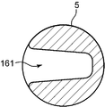
- the hole 161 is formed so as to gradually narrow from the one radial side to the other radial side.
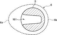
- the hole 161 may extend to a position exceeding the radial center as shown in FIG. 11B.
- the hole 161 is cast with a first sand mold having a portion matched to its shape.
- the hole portion 162 may be formed only by a non-through hole that opens on the other radial side of the shaft portion 5 and extends toward the one radial side.
- the hole 161 shown in FIG. 11B when the hole 161 shown in FIG. 11B is formed, the opening of the hole 161 is formed on the same side as the apex of the nose portion 6a of the first cam portion 6, as shown in FIG. 12A. May be.
- the hole 161 can be formed at an appropriate position according to the stress acting on the shaft 5, and deformation of the shaft 5 can be suppressed.
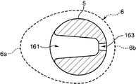
- the hole 163 has a narrower width than the hole 161 and is formed so as to gradually narrow from the radially outer side toward the center.
- the hole 161 can be cast with a first sand mold having a portion matched with the shape, and the hole 163 can be cast with a second sand mold having a portion matched with the shape.
- FIGS. 11B and 11C and FIGS. 12A and 12B can be similarly applied to the hole 38 of the intake camshaft 3.
- the shaft portion 5 of the exhaust camshaft 2 has a circular cross section.
- it may have a hexagonal cross section (regular hexagonal column shape).
- one of the hexagonal apexes is located at a position opposite to the apex of the nose portion 8a of the third cam portion 8 with respect to the center line of the shaft portion 5A, specifically, the nose portion 8a. It is arranged at a position that is approximately 180 ° different from the phase of the vertex.
- the hexagonal top portion of the shaft portion 5A can be disposed at an appropriate position with respect to the nose portion 8a of the third cam portion 8 to suppress deformation of the shaft portion 5A.
- a hole portion 70 including a first hole portion 70a and a second hole portion (not shown) is formed between the fourth cam portion 9 and the fifth cam portion 10, and the sixth cam portion 11 and the seventh cam portion 12, a hole portion 71 including a first hole portion 71 a and a second hole portion (not shown) is formed, and between the eighth cam portion 13 and the Oldham coupling portion 15.
- a hole 72 including a first hole 72a and a second hole (not shown) is formed.
- the holes 70, 71, 72 are holes having a substantially V-shaped cross section similar to the hole 17.
- the holes 71 and 72 have substantially the same length as the hole 17, and the hole 72 has a shorter length than the hole 17.
- the shaft portion 5A having a hexagonal cross-sectional structure when employed, the volume of the shaft portion is reduced as compared with the case where the shaft portion 5 has a circular cross-sectional structure (a circle circumscribing the polygon).
- the exhaust camshaft can be further reduced in weight.
- the original shaft portion 850 of the exhaust camshaft 2A has a hexagonal cross section.
- the first sand mold 840a and the second sand mold 840b constituting the mold 840 are planar surfaces passing through the radial center of the shaft portion 850 and the two top portions 850a and 850b of the hexagonal top portions of the shaft portion 850.
- a part is configured to be parting surfaces M1 and M2.
- the first sand mold 840a and the second sand mold 840b have part of a plane passing through the radial center of the shaft portion 5A and the two top portions of the exhaust camshaft 2A.
- a straight line indicated by a symbol T in FIG. 14 is a diagonal line connecting the two apexes, and corresponds to a split surface of the shaft portion 850.
- the first sand mold 840a and the second sand mold 840b are manufactured, the first sand mold 840a and the second sand mold 840b are prevented from coming off from the hardened cast sand. be able to.
- the first sand mold 840a and the second sand mold 840b can be reliably manufactured, and the exhaust camshaft 2A having the holes 16 and the like can be favorably cast using the mold 840 made of these sand molds.
- the structure and manufacturing method as shown in FIG. 13 and FIG. 14 are also applicable to the intake camshaft 3 and its manufacturing method.
- the shaft portion 5 of the exhaust camshaft 2A (shaft portion 48 of the intake camshaft 3) is replaced with a hexagonal cross-sectional structure, a quadrangular cross-sectional structure (square cross-sectional structure), or an even number of eight or more polygonal cross-sectional structures. It may have (regular polygonal cross-sectional structure). Even in that case, the same effect as in the case of the hexagonal cross-sectional structure can be obtained.
- the embodiment of the intake camshaft 3 can be changed as follows. Similar changes can be made to the exhaust camshaft 2.
- the shaft portion 48 of the intake camshaft 3 has a solid center portion in the radial direction.
- the shaft portion 48 has a hollow center portion in the radial direction. Also good.
- the shaft portion 48 extends in the longitudinal direction of the shaft portion 48 in the length direction, and both end portions of the hole portion 46 of the sprocket mounting portion 28 and the Oldham coupling portion 90 are provided.
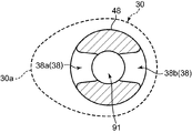
- a hollow portion 91 having a circular cross section communicating with the hole 47 is formed. The hollow portion 91 communicates with the holes 38a, 38b, 39a, 39b, 41a, 41b, 42a, 42b (see FIGS. 15, 16A, and 16B).
- the manufacturing method includes a casting step of casting a solid camshaft (not shown) having a solid shaft portion in which a radial center portion is solid and a plurality of cam portions 30 to 37 are provided on the outer periphery; A hollow portion forming step of forming the hollow portion 91 by cutting the radial center portion of the solid shaft portion using a rotary cutting tool (for example, a gun drill). These steps will be described below.
- a rotary cutting tool for example, a gun drill
- the casting process includes the prototype preparation process, the first sand mold manufacturing process, the second sand mold manufacturing process, the mold manufacturing process, the pouring process, and the camshaft removing process in the method of manufacturing the exhaust camshaft 2. It is comprised from the process similar to each process of these.
- the first thinned portions holes 38a, 38b, 42a, 42b
- the second thinned portions holes 39a, 39b, 41a, 41b
- Each of the meat portions has a size capable of discharging the facet generated at the time of cutting with the rotary cutting tool to the outside.
- the opening width, the opening area, and the like of each thinning portion are set to sizes that allow the facets to pass.
- the hollow portion forming step using a long rotary cutting tool, for example, from the one end side to the other end side of the solid camshaft, the sprocket mounting portion 28, the solid shaft portion, and the Oldham Cutting is performed so as to penetrate the coupling portion 90 in the axial direction.
- the hole 46, the hollow 91, and the hole 47 are formed.
- the hollow portion 91 communicates with the first thinned portion (holes 38a, 38b, 42a, 42b) and the second thinned portion (holes 39a, 39b, 41a, 41b). To be done.
- the hollow portion 91 is formed by cutting the radial center portion of the solid shaft portion using a rotary cutting tool. Further, it is not necessary to use a core in the casting process, and the hollow portion 91 can be easily formed at a relatively low cost.
- the facets generated during the cutting process can be quickly discharged to the outside through the first and second thinning parts, and the efficiency of the cutting process can be effectively increased.
- intake camshaft 3 shown in FIG. 15 can be further modified as follows.
- the first thinning parts (holes 38 a, 38 b, 42 a, 42 b) and the second thinning parts (holes 390 a, 390 b, 410 a, 410 b)
- the first Only the thinning portions (hole portions 38a, 38b, 42a, 42b) communicate with the hollow portion 91
- the second thinning portions (hole portions 390a, 390b, 410a, 410b) communicate with the hollow portion 91.
- the depth of each of the first hole 390a and the second hole 390b constituting the hole 390 and the first hole 410a and the second hole 410b constituting the hole 410 is determined by the hole 38a.
- 38b and the holes 42a, 42b are set to a depth that is shallower than the respective depths and does not reach the hollow portion 91.
- the facets generated when cutting the solid shaft portion can be quickly discharged to the outside through the first wall removal portions (hole portions 38a, 38b, 42a, 42b). Cutting efficiency can be increased.
- the second thinning portion (hole portion 39a). , 39b, 41a, 41b) and the hollow portion 91 communicate with each other, it is possible to suppress a decrease in strength of the shaft portion 48. Thereby, the deformation
- the depth of a 2nd thinning part is mainly set to the depth of a 1st thinning part.
- the width of the second thinned portion is made smaller than the width of the first thinned portion, or the number of the second thinned portions is smaller than the number of the first thinned portions (of the first thinned portion).
- the number can be larger than the number of the second thinned portions), or both of them can be employed.
- a plurality of spline-like grooves may be formed on the outer peripheral surface of the shaft portion.
- exhaust camshaft 2 and the intake camshaft 3 are applied to an in-line four-cylinder diesel engine, but may be applied to a diesel engine having a different number of cylinders. May be applied.
- the present invention is a cast engine camshaft including a shaft portion and a cam portion provided on an outer periphery of the shaft portion, and the shaft portion is a hole opened at a predetermined position on an outer peripheral surface of the shaft portion.
- the hole portion is formed so as to gradually narrow from the radially outer side of the shaft portion toward the center.
- the shaft portion of the camshaft has the hole portion that opens at a predetermined position on the outer peripheral surface of the shaft portion, the amount of the camshaft material corresponding to the volume of the hole portion is reduced, and the camshaft The shaft can be reduced in weight.
- the camshaft can be satisfactorily improved based on the manufacturing method of the present invention as described below. Can be cast.
- the casting method includes: a first prototype component corresponding to one radial portion of the camshaft; and a second prototype component corresponding to the other radial portion of the camshaft.
- a step of preparing a prototype the first prototype component is placed in a casting frame, casting sand is poured into the casting frame and solidified, and the first prototype component is removed from the solidified casting sand.
- a step of manufacturing the first sand mold, and the second prototype component is disposed in the casting frame, the casting sand is put into the casting frame and solidified, and the second casting mold is solidified from the solidified casting sand.
- a step of manufacturing a second sand mold by removing the component a step of manufacturing a mold having a cavity in which the camshaft is cast by combining the first sand mold and the second sand mold, and the cavity Molten metal inside
- a step of pouring chill by collapsing removing the mold and a step of taking out the camshaft from above the mold.
- a prototype having a hole having the same shape as the hole is prepared in the step of preparing the prototype. That is, the original shaft portion has a hole portion that opens at a predetermined position on the outer peripheral surface of the shaft portion and gradually narrows from the radially outer side toward the center. Since the constricted shape of the hole serves as a draft, when the hole of the camshaft is cast with the first sand mold, the first prototype constituent part is easily and reliably removed from the solidified sand. Thus, the first sand mold can be reliably manufactured. The same applies to the case where the hole of the camshaft is cast with the second sand mold.
- the hole includes a first hole that opens on one radial side of the shaft and a second hole that opens on the other radial side of the shaft. It is preferable that each of the hole and the second hole is formed so as to gradually narrow from the radially outer side of the shaft toward the center.
- each of the first hole portion and the second hole portion is formed so as to gradually narrow from the radially outer side of the shaft portion toward the center.
- a mold for casting camshafts each having a hole in the other radial portion can be reliably manufactured, and the camshaft having the hole can be reliably cast using this mold.
- the first hole is preferably formed in the same shape as the second hole at a position symmetrical to the second hole with respect to the shaft center line. .
- the holes can be arranged in a well-balanced manner on the one radial side and the other radial side of the camshaft, and as a result, the strength of the shaft portion can be reduced between the radial one side and the radial other side. Can ensure a good balance.
- the hole portion preferably penetrates the shaft portion in the radial direction.
- the volume of the hole can be increased, and the camshaft can be further reduced in weight.
- the cam portion includes a nose portion protruding radially outward from a base circle, and the hole portion is a non-through hole extending in a radial direction from a predetermined position on the nose portion side of the shaft portion. Preferably there is.
- the hole can be formed at an appropriate position according to the stress acting on the shaft, and the deformation of the shaft can be suppressed. More specifically, in the vicinity of the portion of the shaft portion where the cam portion is provided, a larger stress acts on the portion on the opposite side in the radial direction than the nose portion side portion.
- the hole portion is a non-through hole extending in a radial direction from a predetermined position on the nose portion side of the shaft portion. Therefore, a portion of the shaft portion on the side opposite to the nose portion in the radial direction is a nose portion side portion. Therefore, the strength of the shaft portion is higher than that of the shaft portion. Therefore, deformation of the shaft portion can be suppressed.
- the cam portion includes a nose portion protruding radially outward from a base circle, and the hole portion is a third hole portion extending in a radial direction from a predetermined position on the nose portion side of the shaft portion. And a fourth hole extending in a radial direction from a predetermined position on the opposite side to the nose of the shaft, and the fourth hole is formed shallower than the third hole. It is preferable.
- the hole can be formed at an appropriate depth according to the stress acting on the shaft, and deformation of the shaft can be suppressed. More specifically, in the vicinity of the portion of the shaft portion where the cam portion is provided, a larger stress acts on the portion on the opposite side in the radial direction than the nose portion side portion.
- the fourth hole extending in the radial direction from the predetermined position on the opposite side to the nose portion of the shaft portion is shallower than the third hole portion extending in the radial direction from the predetermined position on the nose portion side of the shaft portion. Since the shaft portion is formed, the portion of the shaft portion on the side opposite to the nose portion in the radial direction has higher strength than the nose portion side portion, and therefore, deformation of the shaft portion can be suppressed.
- the shaft portion has a polygonal cross-sectional structure having an even number of top portions of 4 or more, and the cam portion includes a nose portion projecting radially outward from a base circle, of the top portions.
- One is preferably disposed at a position opposite to the apex of the nose portion with respect to the center line of the shaft portion.
- the shaft portion of the camshaft has a polygonal cross-sectional structure having an even number of tops of 4 or more, the shaft portion of the camshaft has a circular cross-sectional structure (a circle circumscribing the polygon)
- the volume of the shaft portion can be reduced, and thus the camshaft can be further reduced in weight.
- the deformation of the shaft portion can be suppressed by arranging the top portion of the shaft portion at an appropriate position with respect to the nose portion of the cam portion. Specifically, in the vicinity of the portion of the shaft portion where the cam portion is provided, the greatest stress acts on the portion of the shaft portion on the side opposite to the apex of the nose portion with respect to the center line of the shaft portion. In the above configuration, one of the top portions of the shaft portion is disposed at a position opposite to the apex of the nose portion with respect to the center line of the shaft portion. It is possible to suppress the deformation of the shaft portion by increasing the strength relative to other portions.
- the shaft portion of the camshaft has a polygonal cross-sectional structure having an even number of top portions of 4 or more, and the first sand mold and the second sand mold are respectively shafts of the camshaft. It is preferable that a part of the plane passing through the center in the radial direction of the part and the two tops is a parting surface.
- the shaft portion of the camshaft has a polygonal cross-sectional structure having an even number of tops of 4 or more
- the shaft portion of the camshaft has a circular cross-sectional structure (a circle circumscribing the polygon)
- the volume of the shaft portion can be reduced, and thus the camshaft can be further reduced in weight.
- first sand mold and the second sand mold each have a part of a plane passing through the radial center of the shaft portion of the camshaft and the two top portions, the first sand mold and the second sand mold. Can be prevented from being removed from the solidified casting sand, whereby the camshaft can be cast satisfactorily.
- a multi-cylinder engine cam comprising a shaft portion extending in a cylinder row direction of an engine having a plurality of cylinders, and a plurality of cam portions provided on an outer periphery of the shaft portion.
- the cam portion is provided at a position corresponding to the cylinder on the inner side of both end portions of the shaft portion, and the shaft portion is located at least at one end of the shaft portion and the end portion.
- a first thinning portion formed in a first section which is a section between the cam section and a cam section corresponding to one cylinder of two adjacent cylinders and a cam section corresponding to the other cylinder;
- a second gradually-thickening portion formed in a second section that is a section between the first and second thinning portions, and the strength of the shaft portion in the second section is , Formed so as to be larger than the strength of the shaft portion in the first section A.
- the “thickening part” is a part of the outer periphery of the shaft part having the same outer diameter so that a part of the sectional area in the length direction is smaller than a sectional area of the part other than the part. It refers to a hole (including a recess and a through hole) or a notch formed in the surface.
- the shaft portion has the first thinning portion and the second thinning portion, compared with the case where the first thinning portion and the second thinning portion are not provided,
- the camshaft can be reduced in weight by the weight corresponding to the volume of the thickness removing part.
- the deformation of the shaft portion can be effectively suppressed for the following reasons. That is, the stress generated in the shaft portion when the shaft portion receives a force from the cam portion (stress to twist the shaft portion and stress to bend the shaft portion) is in the axial direction (length direction). Specifically, the stress generated in the second section is larger than the stress generated in the first section. This is because the force transmitted from the cam portion increases as the distance from the cam portion in the shaft portion increases. Further, in the first section, the force is transmitted only from one side in the axial direction. This is because the above-mentioned force is transmitted from both axial sides in the two sections.
- the first and second thinning portions are formed such that the strength of the shaft portion in the second section is greater than the strength of the shaft portion in the first section. Therefore, even if a larger stress is generated in the second section than in the first section, the deformation of the shaft portion in the second section can be suppressed. Thereby, it is possible to effectively suppress the occurrence of inconveniences such as variations in the valve lift amount among the cylinders.
- each of the first thinning portion and the second thinning portion is a non-through hole that opens to an outer peripheral surface of the shaft portion, and the depth of the second thinning portion is It is preferable that it is shallower than the depth of the first thinned portion.
- each of the first and second thinning portions is a non-through hole that opens to the outer peripheral surface of the shaft portion, and thus the thinning portions can be easily formed. Moreover, since the depth of the second thinned portion is shallower than the depth of the first thinned portion, the strength of the shaft portion in the second section is easier and more reliable than the strength of the shaft portion in the first section. Can be bigger.
- each of the first thinning portion and the second thinning portion is a non-through hole that opens in an outer peripheral surface of the shaft portion, and extends in a length direction of the shaft portion.
- the depth of the first thinned portion is constant in the length direction, and the depth of the second thinned portion gradually decreases from the central portion in the length direction toward both ends in the length direction. It is preferable.
- each of the first and second thinning portions is a non-through hole that opens to the outer peripheral surface of the shaft portion, and thus the thinning portions can be easily formed.
- the first and second thinning portions extend in the length direction of the shaft portion, and the first thinning portion has a constant depth in the length direction, and the second thinning portion Since the depth gradually decreases from the central portion in the length direction toward both ends in the length direction, the strength of the shaft portion in the second section can be made easier than the strength of the shaft portion in the first section. Can be bigger. More specifically, since the depth of the first thinned portion is constant in the length direction, the strength of the shaft portion in the section where the first thinned portion is formed in the first section is substantially constant.
- the strength of the shaft portion at a position where the stress is relatively small (position far from the cam portion) can be made larger, and thereby the strength of the shaft portion in the second section can be made larger than the strength of the shaft section in the first section. Can be easily enlarged.
- the first thinning portion is a through hole that penetrates the shaft portion in a radial direction
- the second thinning portion is a non-through hole that opens on an outer peripheral surface of the shaft portion. Is preferred.
- the strength of the shaft portion in the second section can be easily and reliably increased than the strength of the shaft portion in the first section.
- the shaft portion includes a hollow portion extending in a length direction of the shaft portion at a radial center portion, and each of the first thinning portion and the second thinning portion is the hollow portion. It is preferable to communicate with the part.
- the shaft portion has a hollow portion extending in the length direction of the shaft portion at the radial center portion, the volume of the hollow portion is smaller than when the hollow portion is not provided.
- the camshaft can be further reduced in weight by the weight corresponding to.
- first and second thinning portions are respectively communicated with the hollow portion, when the hollow portion is formed using a rotary cutting tool, the solid shaft portion is cut.
- the facets that are generated in the process can be quickly discharged to the outside through the first and second thinning portions, and as a result, the efficiency of cutting can be increased.
- the shaft portion has a hollow portion extending in a length direction of the shaft portion at a radial center portion, and the first thinning portion and the second thinning portion among the first thinning portion. It is preferable that only the thinned portion communicates with the hollow portion.
- the shaft portion has a hollow portion extending in the length direction of the shaft portion at the radial center portion, the volume of the hollow portion is smaller than when the hollow portion is not provided.
- the camshaft can be further reduced in weight by the weight corresponding to.
- the first thinned portion communicates with the hollow portion, when the hollow portion is formed using a rotary cutting tool, the facet generated when cutting the solid shaft portion is replaced with the first cut portion. It can be quickly discharged to the outside through one thinning portion, and as a result, the efficiency of cutting can be increased.
- the 1st thinning part and the 2nd thinning part since only the 1st thinning part is connected with the above-mentioned hollow part, in the above-mentioned 2nd section, the 2nd thinning part and the hollow part are connected. By doing so, it is possible to suppress a decrease in the strength of the shaft portion, and thereby it is possible to more effectively suppress the deformation of the shaft portion in the second section.
- a solid camshaft having a solid shaft portion in which a central portion in a radial direction is solid and the plurality of cam portions are provided on an outer periphery is cast.
- the hollow portion is formed by cutting the radial center portion of the solid shaft portion using a rotary cutting tool, the core is formed in the casting process in order to form the hollow portion. There is no need to use it, and the hollow portion can be easily formed at a relatively low cost.
- the thinned portion that communicates with the hollow portion in the hollow portion forming step is the rotary cutting tool. It is preferable to have a size that allows the facets generated during the cutting process to be discharged to the outside.
- the thinned portion communicating with the hollow portion in the hollow portion forming step has a size capable of discharging the face generated when cutting with the rotary cutting tool to the outside. Therefore, it is possible to quickly discharge the facets generated at the outside through the thinning portion, and to effectively increase the efficiency of the cutting process.
Landscapes
- Engineering & Computer Science (AREA)
- Mechanical Engineering (AREA)
- General Engineering & Computer Science (AREA)
- Ocean & Marine Engineering (AREA)
- Valve-Gear Or Valve Arrangements (AREA)
Abstract
排気カムシャフト2は、軸部(5)と当該軸部(5)の外周に設けられたカム部(6~13)とを備える。軸部(5)は、当該軸部(5)の外周面の所定位置で開口する孔部(16、17、19)を有する。前記孔部(16、17、19)は、前記軸部(5)の径方向外側から中心に向かって次第に窄まるように形成されている。
Description
本発明は、エンジン用カムシャフトおよびその製造方法に関する。
従来、エンジンのカムシャフトには、カムシャフトの軸部が中実に形成されたもの(中実タイプ)と、カムシャフトの軸部が長さ方向全体に亘って中空に形成されたもの(中空タイプ)とが存在し、特許文献1には、中空タイプのカムシャフトの製造方法の一例が開示されている。
特許文献1に記載のカムシャフトの製造方法は、砂等からなる崩壊性の主型内に砂等からなる崩壊性の中子を配置することで鋳型を製造する工程と、上記主型と中子との間に形成されるキャビティ内に溶湯を流し込む工程と、溶湯の冷却後に鋳型を崩壊除去する工程とを備えている。また、上記中子には、その外周面から径方向に突出する位置決め用の複数のピンが設けられており、この複数のピンにより、主型内において中子が位置決めされる。
特許文献1に記載のカムシャフトの製造方法によれば、中実タイプのカムシャフトと比べて軽量化されたカムシャフトを製造することができるものの、以下の問題が生じる虞がある。
すなわち、カムシャフトの軸部を中空にするために中子を準備して、これを主型内に配置する必要があり、さらに、主型内に中子を正確に位置決めするために、中子に上記ピンを突設する必要があるため、鋳型の部品点数が増加して、鋳型の製造コストが増加するという問題がある。さらに、主型から脱型されたカムシャフトの軸孔から、ショットブラスト等により中子を崩壊除去する必要があるため、中実タイプと比べてカムシャフトの製造工程が大幅に増加するという問題がある。
本発明は、軽量でありながら容易に製造することができるエンジン用カムシャフトおよびその製造方法を提供することを目的とする。
そして、本発明は、軸部と当該軸部の外周に設けられたカム部とを備える鋳造製のエンジン用カムシャフトであって、前記軸部は、当該軸部の外周面の所定位置で開口する孔部を有し、前記孔部は、前記軸部の径方向外側から中心に向かって次第に窄まるように形成されているものである。
また、本発明は、上記エンジン用カムシャフトの製造方法であって、前記カムシャフトの径方向一方側部分に対応する第1原型構成部と、前記カムシャフトの径方向他方側部分に対応する第2原型構成部とで構成される前記カムシャフトの原型を準備する工程と、前記第1原型構成部を鋳枠内に配置して、当該鋳枠内に鋳造砂を投入して固化させ、当該固化した鋳造砂から前記第1原型構成部を取り外すことにより第1砂型を製造する工程と、前記第2原型構成部を鋳枠内に配置して、当該鋳枠内に鋳造砂を投入して固化させ、当該固化した鋳造砂から前記第2原型構成部を取り外すことにより第2砂型を製造する工程と、前記第1砂型と前記第2砂型とを互いに組み合わせることにより、前記カムシャフトが鋳造されるキャビティを有する鋳型を製造する工程と、前記キャビティ内に溶湯を注いで冷却硬化させる工程と、前記鋳型を崩壊除去することにより、前記鋳型から前記カムシャフトを取り出す工程とを備えるものである。
以下、添付図面を参照しながら本発明の好ましい実施形態について詳述する。
<カムシャフトを備えるエンジンの構造>
本発明の実施形態に係るカムシャフトを備えるエンジンは、直列4気筒の4サイクルディーゼルエンジンであり、図1に示されるように、シリンダブロック(図示略)と、このシリンダブロックの上に組み付けられたシリンダヘッド72とを備えている。図1に示されるエンジンでは、図示は省略するが、左側から順に、第1気筒、第2気筒、第3気筒、第4気筒の4つの気筒が並んでいる。
本発明の実施形態に係るカムシャフトを備えるエンジンは、直列4気筒の4サイクルディーゼルエンジンであり、図1に示されるように、シリンダブロック(図示略)と、このシリンダブロックの上に組み付けられたシリンダヘッド72とを備えている。図1に示されるエンジンでは、図示は省略するが、左側から順に、第1気筒、第2気筒、第3気筒、第4気筒の4つの気筒が並んでいる。
上記シリンダヘッド72は、気筒毎に、燃焼室に連通する2つの排気ポートおよび2つの吸気ポートと、各排気ポートを燃焼室から遮断するための排気バルブと、各吸気ポートを燃焼室から遮断するための吸気バルブとを備えており(いずれも図示略)、さらに、各排気バルブを駆動して各排気ポートを所定のタイミングで開閉させる排気バルブ駆動機構78と、各吸気バルブを駆動して各吸気ポートを所定のタイミングで開閉させる吸気バルブ駆動機構73と、後述の排気カムシャフト2を回転自在に支持する4つの軸受部24~27と、後述の吸気カムシャフト3を回転自在に支持する4つの軸受部74~77とを備えている。
排気バルブ駆動機構78は、排気カムシャフト2を備え、吸気バルブ駆動機構73は、吸気カムシャフト3を備えている。これら排気カムシャフト2および吸気カムシャフト3は、チェーンおよびスプロケット等から構成される周知の動力伝達機構を介してクランクシャフトに連結されている。さらに、排気バルブ駆動機構78は、排気バルブを閉方向に付勢するリターンスプリング(図示略)を備え、吸気バルブ駆動機構73は、吸気バルブを閉方向に付勢するリターンスプリング(図示略)を備えている。上記排気カムシャフト2および上記吸気カムシャフト3は、それぞれ、クランクシャフトの駆動力により、リターンスプリングの付勢力に抗して排気バルブおよび吸気バルブを開弁させる。これら排気カムシャフト2および吸気カムシャフト3は、本発明の「エンジン用カムシャフト」に相当する。
<排気カムシャフトの構造>
図1~3に示されるように、上記排気カムシャフト2は、気筒列方向に延びる円柱状の軸部5と、この軸部5の外周に一体に設けられた8つのカム部(図1の左側から順に、第1カム部6、第2カム部7、第3カム部8、第4カム部9、第5カム部10、第6カム部11、第7カム部12、および第8カム部13)と、上記軸部5の外周に一体に設けられ、上記軸受部24~27にそれぞれ回転自在に支持されるジャーナル部20~23(図2参照)と、タイミングチェーンが巻き掛けられるスプロケット(図示略)が取り付けられ、上記軸部5の一方側の端部に一体に設けられるスプロケット取付部4と、上記軸部5の他方側の端部に一体に設けられ、燃料ポンプの駆動軸(図示略)が連結されるオルダムカップリング部15とを備えている。図1に示される例では、排気カムシャフト2は、左側から見て時計回り方向(右回り方向)に回転する。
図1~3に示されるように、上記排気カムシャフト2は、気筒列方向に延びる円柱状の軸部5と、この軸部5の外周に一体に設けられた8つのカム部(図1の左側から順に、第1カム部6、第2カム部7、第3カム部8、第4カム部9、第5カム部10、第6カム部11、第7カム部12、および第8カム部13)と、上記軸部5の外周に一体に設けられ、上記軸受部24~27にそれぞれ回転自在に支持されるジャーナル部20~23(図2参照)と、タイミングチェーンが巻き掛けられるスプロケット(図示略)が取り付けられ、上記軸部5の一方側の端部に一体に設けられるスプロケット取付部4と、上記軸部5の他方側の端部に一体に設けられ、燃料ポンプの駆動軸(図示略)が連結されるオルダムカップリング部15とを備えている。図1に示される例では、排気カムシャフト2は、左側から見て時計回り方向(右回り方向)に回転する。
上記排気カムシャフト2において、上記第1カム部6と上記第2カム部7は、各々、第1気筒に対応して設けられる偏心カムであり、これらは上記ジャーナル部20を介して互いに隣接している(図2~4参照)。そして、これら第1カム部6、第2カム部7、およびジャーナル部20は、第1気筒の上方かつ排気側に位置している。同様に、上記第3カム部8と上記第4カム部9は、各々、第2気筒に対応して設けられる偏心カムであり、これらは上記ジャーナル部21を介して互いに隣接している。そして、これら第3カム部8、第4カム部9、およびジャーナル部21は、第2気筒の上方かつ排気側に位置している。上記第5カム部10と上記第6カム部11は、各々、第3気筒に対応して設けられる偏心カムであり、これらは上記ジャーナル部22を介して互いに隣接している。そして、これら第5カム部10、第6カム部11、およびジャーナル部22は、第3気筒の上方かつ排気側に位置している。上記第7カム部12と上記第8カム部13は、各々、第4気筒に対応して設けられる偏心カムであり、これらは上記ジャーナル部23を介して互いに隣接している。そして、これら第7カム部12、第8カム部13、およびジャーナル部23は、第4気筒の上方かつ排気側に位置している。上記カム部6~13は、それぞれ、ベース円から径方向外側に突出する1つのノーズ部6a~13a(図2参照)を備えている。
なお、本実施形態におけるエンジンは、各気筒の爆発順序が、第1気筒→第3気筒→第4気筒→第2気筒とされており、これに伴い、排気カムシャフト2のカム部6~13は、排気カムシャフト2の90°回転ごとに、上記の爆発順序で排気バルブを開弁するように、互いに位相差を有して設けられている(図2参照)。
上記排気カムシャフト2の軸部5は、上記スプロケット取付部4と第1カム部6との間の区間(本発明の「第1区間」に相当する。以下の説明において「第1区間」と称する場合がある)に位置する孔部16と、上記第2カム部7と上記第3カム部8との間の区間(本発明の「第2区間」に相当する。以下の説明において「第2区間」と称する場合がある)に位置する孔部17と、上記第4カム部9と上記第5カム部10との間に位置する回転角度調節部18と、上記第6カム部11と上記第7カム部12との間の区間(本発明の「第2区間」に相当する。以下の説明において「第2区間」と称する場合がある)に位置する孔部19およびカムシャフト識別リング14とを有している。
上記孔部16は、図5及び図7Aに示されるように、軸部5の径方向一方側の所定位置で開口する第1孔部16aと、軸部5の径方向他方側の所定位置で開口する第2孔部16bとを備えている。上記第1孔部16aおよび上記第2孔部16bは、各々、軸部5の長さ方向に延びており、軸部5の径方向外側から中心に向かって次第に窄まるように形成されている。より具体的には、孔部16aおよび孔部16bは、各々、軸部5の外周面において、軸部5の長さ方向に延びる長方形の両端部に半円を組み合わせた形状で開口する開口部16eと、この開口部16eと略同じ形状で当該開口部16eの開口面積よりも小さい面積を有する略平坦な底部16dと、上記開口部16eと上記底部16dとを繋ぐ周壁部16cとを有している。上記底部16dは長さ方向全体に亘って略同じ深さを有しており、周壁部16cと底部16dとの境界部は曲面状に形成されている。
そして、第1孔部16aは、軸部5の中心線に対して第2孔部16bとは対称となる位置で、第2孔部16bと同一の大きさで同一形状に形成されている。また、第1孔部16aは、第1カム部6のノーズ部6aの頂点側、具体的には当該頂点と位相(回転位相)が同じ位置に形成され、第2孔部16bは、第1カム部6のノーズ部6aとは反対側、具体的にはノーズ部6aの頂点とは位相が略180°異なる位置に形成されている。上記第1孔部16aおよび上記第2孔部16bは、本発明の「第1除肉部」に相当する。以下の説明では、これらの孔部16a,16bを「第1除肉部」と称する場合がある。
上記孔部17は、図5及び図7Bに示されるように、軸部5の径方向一方側の所定位置で開口する第1孔部17aと、軸部5の径方向他方側の所定位置で開口する第2孔部17bとを備えている。上記第1孔部17aおよび上記第2孔部17bは、各々、軸部5の長さ方向に延びており、軸部5の径方向外側から中心に向かって次第に窄まるように形成されている。
より具体的には、第1孔部17aおよび第2孔部17bは、各々、軸部5の外周面において、軸部5の長さ方向に延びる長方形の両端部に半円を組み合わせた形状の開口部17eと、この開口部17eよりも狭い幅で軸部5の長さ方向に延びてその長さ方向両端部から中央部にかけて次第に深くなる(径方向中心に近づく)ように形成され、換言すれば、軸部5の長さ方向中央部から長さ方向両端部にかけて次第に浅くなるように形成され、長さ方向両端部が上記開口部17eと連続する断面略V字状のスロープ部17dと、このスロープ部17dの幅方向両端部から立ち上がり、上記開口部17eの幅方向端部と連続する側壁部17cとを有している。上記スロープ部17dの底部(V字の下端部)は曲面状に形成されており、当該底部の深さ(第1孔部17aおよび第2孔部17bの各々の最深部の深さ)は、上記第1孔部16aおよび第2孔部16bの深さと略同じに設定されている。つまり、第2カム部7と第3カム部8との間の区間における軸部5の径(直径)は、スプロケット取付部4と第1カム部6との間の区間における軸部5の径よりも大きく設定されており、しかも、第1孔部17aおよび第2孔部17bにおけるスロープ部17dの底部が曲面状に形成されて当該底部に応力集中が生じにくくなっている。このため、第2カム部7と第3カム部8との間の区間における軸部5の強度は、スプロケット取付部4と第1カム部6との間の区間における軸部5の強度よりも大きくなっている。
そして、第1孔部17aは、軸部5の中心線に対して第2孔部17bとは対称となる位置で、第2孔部17bと同一の大きさで同一形状に形成されている。また、第1孔部17aは、第3カム部8のノーズ部8aの頂点に対して位相が略90°遅れた位置に形成され、第2孔部17bは、第3カム部8のノーズ部8aの頂点に対して位相が略90°進んだ位置に形成されている。上記第1孔部17aおよび上記第2孔部17bは、本発明の「第2除肉部」に相当する。以下の説明では、これらの孔部17a,17bを「第2除肉部」と称する場合がある。
上記回転角度調節部18は、軸部5の外周から径方向外側に突出する断面6角形状(正6角形)の部分である。この回転角度調節部18は、エンジン点検時等にスパナと係合されて用いられるものである。すなわち、エンジンの点検時等において、スパナの先端開口部に回転角度調節部18を係合させてスパナを回転させることにより、軸部5を回転させて排気バルブで排気ポートを閉じることができ、これにより、エンジン点検時等に排気ポートから埃などの異物が侵入するのを防止することができる。
上記孔部19は、図5に示されるように、軸部5の径方向一方側の所定位置で開口する第1孔部19aと、軸部5の径方向他方側の所定位置で開口する第2孔部19bとを備えている。第1孔部19aおよび第2孔部19bは、軸部5の径方向外側から中心に向かって次第に窄まるように形成されており、より具体的には、上記孔部17aおよび孔部17bと同様に断面略V字状に形成されているが、カムシャフト識別リング14との干渉を避けるために、上記孔部17aおよび孔部17bよりも軸部5の長さ方向に短く形成されている。また、第1孔部19aは、第6カム部11のノーズ部11a(図2参照)の頂点に対して位相が略90°進んだ位置に形成され、第2孔部19bは、第6カム部11のノーズ部11aの頂点に対して位相が略90°遅れた位置に形成されている。
上記第2カム部7と上記第3カム部8との間の区間と同様に、第6カム部11と第7カム部12との間の区間における軸部5の径(直径)は、スプロケット取付部4と第1カム部6との間の区間における軸部5の径よりも大きく設定されており、しかも、第1孔部19aおよび第2孔部19bにおけるスロープ部の底部が曲面状に形成されて当該底部に応力集中が生じにくくなっている。このため、第6カム部11と第7カム部12との間の区間における軸部5の強度は、スプロケット取付部4と第1カム部6との間の区間における軸部5の強度よりも大きくなっている。上記第1孔部19aおよび上記第2孔部19bは、本発明の「第2除肉部」に相当する。以下の説明では、これらの孔部19a,19bを「第2除肉部」と称する場合がある。
上記カムシャフト識別リング14は、軸部5の外周から径方向外側にリング状に突出する部分である。軸部5の長さ方向におけるカムシャフト識別リング14の配設位置は、車種別に異なっており、エンジンの組み立て時にカムシャフト識別センサがカムシャフト識別リング14の位置を読み取ることにより、エンジン組み立て装置が排気カムシャフト2の対応車種等を識別できるようになっている。
なお、図5に示されるように、スプロケット取付部4の径方向中心部には、その軸方向(長さ方向)に延びる孔部45が形成されている。また、オルダムカップリング部15には、その内部を軸方向(長さ方向)に貫く孔部43が形成され、さらに、軸部5のうち、オルダムカップリング部15側の端部からジャーナル部23に対応する部分に亘って、その長さ方向に延びて上記孔部43と連通する孔部44が形成されている。
<吸気カムシャフトの構造>
図1及び図4に示されるように、上記吸気カムシャフト3は、気筒列方向に延びる円柱状の軸部48と、この軸部48の外周に一体に設けられた8つのカム部(図1の左側から順に、第1カム部30、第2カム部31、第3カム部32、第4カム部33、第5カム部34、第6カム部35、第7カム部36、および第8カム部37)と、上記軸部48の外周に一体に設けられ、上記軸受部74~77にそれぞれ回転自在に支持されるジャーナル部49~52(図6参照)と、タイミングチェーンが巻き掛けられるスプロケット(図示略)が取り付けられ、上記軸部48の一方側の端部に一体に設けられるスプロケット取付部28と、燃料ポンプの駆動軸(図示略)が連結され、上記軸部48の他方側の端部に一体に設けられるオルダムカップリング部90とを備えている。図1に示される例では、吸気カムシャフト3は、左側から見て反時計回り方向(左回り方向)に回転する。
図1及び図4に示されるように、上記吸気カムシャフト3は、気筒列方向に延びる円柱状の軸部48と、この軸部48の外周に一体に設けられた8つのカム部(図1の左側から順に、第1カム部30、第2カム部31、第3カム部32、第4カム部33、第5カム部34、第6カム部35、第7カム部36、および第8カム部37)と、上記軸部48の外周に一体に設けられ、上記軸受部74~77にそれぞれ回転自在に支持されるジャーナル部49~52(図6参照)と、タイミングチェーンが巻き掛けられるスプロケット(図示略)が取り付けられ、上記軸部48の一方側の端部に一体に設けられるスプロケット取付部28と、燃料ポンプの駆動軸(図示略)が連結され、上記軸部48の他方側の端部に一体に設けられるオルダムカップリング部90とを備えている。図1に示される例では、吸気カムシャフト3は、左側から見て反時計回り方向(左回り方向)に回転する。
上記吸気カムシャフト3において、上記第1カム部30と上記第2カム部31は、各々、第1気筒に対応して設けられる偏心カムであり、これらは上記ジャーナル部49(図6参照)を介して互いに隣接している。そして、これら第1カム部30、第2カム部31、およびジャーナル部49は、第1気筒の上方かつ吸気側に位置している。上記第3カム部32と上記第4カム部33は、各々、第2気筒に対応して設けられる偏心カムであり、これらは上記ジャーナル部50を介して互いに隣接している。そして、これら第3カム部33、第4カム部34、およびジャーナル部50は、第2気筒の上方かつ吸気側に位置している。上記第5カム部34と上記第6カム部35は、各々、第3気筒に対応して設けられる偏心カムであり、これらは上記ジャーナル部51を介して互いに隣接している。そして、これら第5カム部34、第6カム部35、およびジャーナル部51は、第3気筒の上方かつ吸気側に位置している。上記第7カム部36と上記第8カム部37は、各々、第4気筒に対応して設けられる偏心カムであり、これらは上記ジャーナル部52を介して互いに隣接している。そして、これら第7カム部36、第8カム部37、およびジャーナル部52は、第4気筒の上方かつ吸気側に位置している。上記カム部30~37は、それぞれ、ベース円から径方向外側に突出する1つのノーズ部30a~37a(図1,6参照)を備えている。
なお、上述のように、各気筒の爆発順序が、第1気筒→第3気筒→第4気筒→第2気筒となっていることに伴い、吸気カムシャフト3のカム部30~37は、吸気カムシャフト3の90°回転ごとに、上記の爆発順序で吸気バルブを開弁するように、互いに位相差を有して設けられている。
上記吸気カムシャフト3の軸部48は、上記スプロケット取付部28と第1カム部30との間の区間(本発明の「第1区間」に相当する。以下の説明において「第1区間」と称する場合がある)に位置する孔部38と、上記第2カム部31と上記第3カム部32との間の区間(本発明の「第2区間」に相当する。以下の説明において「第2区間」と称する場合がある)に位置するカムシャフト識別リング53および孔部39と、上記第4カム部33と上記第5カム部34との間に位置する回転角度調節部40と、上記第6カム部35と上記第7カム部36との間の区間(本発明の「第2区間」に相当する。以下の説明において「第2区間」と称する場合がある)に位置する孔部41と、上記第8カム部37と上記オルダムカップリング部90との間の区間(本発明の「第1区間」に相当する。以下の説明において「第1区間」と称する場合がある)に位置する孔部42とを有している。
上記孔部38は、図6に示されるように、軸部48径方向一方側の所定位置で開口する第1孔部38aと、軸部48の径方向他方側の所定位置で開口する第2孔部38bとを備えている。上記第1孔部38aおよび上記第2孔部38bは、各々、軸部48の長さ方向に延びており、排気カムシャフト2の上記孔部16と同様に、軸部48の径方向外側から中心に向かって次第に窄まるように形成されている。また、第1孔部38aは、第1カム部30のノーズ部30aの頂点側、具体的には当該頂点と位相が略同じ位置に形成され、第2孔部38bは、第1カム部30のノーズ部30aとは反対側、具体的にはノーズ部30aの頂点とは位相が略180°異なる位置に形成されている。上記第1孔部38aおよび上記第2孔部38bは、本発明の「第1除肉部」に相当する。以下の説明では、これらの孔部38a,38bを「第1除肉部」と称する場合がある。
上記孔部39は、図6に示されるように、軸部48の径方向一方側の所定位置で開口する第1孔部39aと、軸部48の径方向他方側の所定位置で開口する第2孔部39bとを備えている。上記第1孔部39aおよび上記第2孔部39bは、各々、軸部48の長さ方向に延びており、排気カムシャフト2の上記孔部17と同様に、軸部48の径方向外側から中心に向かって次第に窄まるように形成されている。なお、第1孔部39aおよび第2孔部39bは、カムシャフト識別リング53との干渉を避けるために、排気カムシャフト2の上記孔部17aおよび孔部17bよりも短く形成されている。また、第1孔部39aは、第3カム部32のノーズ部32a(図1参照)の頂点に対して位相が略90°遅れた位置に形成され、第2孔部39bは、第3カム部32のノーズ部32aの頂点に対して位相が略90°進んだ位置に形成されている。上記第1孔部39aおよび上記第2孔部39bは、本発明の「第2除肉部」に相当する。以下の説明では、これらの孔部39a,39bを「第2除肉部」と称する場合がある。
上記孔部41は、図6に示されるように、軸部48の径方向一方側の所定位置で開口する第1孔部41aと、軸部48の径方向他方側の所定位置で開口する第2孔部41bとを備えている。第1孔部41aおよび第2孔部41bは、各々、軸部48の長さ方向に延びており、排気カムシャフト2の上記孔部19と同様に、軸部48の径方向外側から中心に向かって次第に窄まるように形成されている。また、第1孔部41aは、第6カム部35のノーズ部35a(図1参照)の頂点に対して位相が略90°進んだ位置に形成され、第2孔部41bは、第6カム部35のノーズ部35aの頂点に対して位相が略90°遅れた位置に形成されている。上記第1孔部41aおよび上記第2孔部41bは、本発明の「第2除肉部」に相当する。以下の説明では、これらの孔部41a,41bを「第2除肉部」と称する場合がある。
上記孔部42は、図6に示されるように、軸部48の径方向一方側の所定位置で開口する第1孔部42aと、軸部48の径方向他方側の所定位置で開口する第2孔部42bとを備えている。第1孔部42aおよび第2孔部42bは、各々、軸部48の長さ方向に延びており、上記孔部41と同様に、軸部48の径方向外側から中心に向かって次第に窄まるように形成されている。なお、第1孔部42aおよび第2孔部42bは、上記孔部41aおよび孔部41bよりも軸部48の長さ方向に短く形成されている。また、第1孔部42aは、第8カム部37のノーズ部37aの頂点とは位相が略180°異なる位置に形成され、第2孔部42bは、第8カム部37のノーズ部37aの頂点とは位相が略同じ位置に形成されている。上記第1孔部42aおよび上記第2孔部42bは、本発明の「第1除肉部」に相当する。以下の説明では、これらの孔部42a,42bを「第1除肉部」と称する場合がある。
なお、図1に符号61、60、62で示される孔部は、それぞれ、第1気筒に対応する吸気バルブの軸部が挿通される孔部、排気バルブの軸部が挿通される孔部、燃料噴射弁が設けられる孔部である。同様に、符号64、63、65で示される孔部は、それぞれ、第2気筒に対応する吸気バルブの軸部が挿通される孔部、排気バルブの軸部が挿通される孔部、燃料噴射弁が設けられる孔部である。また、符号67、66、68で示される孔部は、それぞれ、第3気筒に対応する吸気バルブの軸部が挿通される孔部、排気バルブの軸部が挿通される孔部、燃料噴射弁が設けられる孔部である。そして、符号91、69、71で示される孔部は、第4気筒に対応する吸気バルブの軸部が挿通される孔部、排気バルブの軸部が挿通される孔部、燃料噴射弁が設けられる孔部である。
なお、図6に示されるように、スプロケット取付部28の径方向中心部には、その軸方向(長さ方向)に延びる孔部46が形成されている。また、オルダムカップリング部90には、その内部を軸方向(長さ方向)に貫く孔部47が形成されている。
<排気カムシャフトの製造方法>
次に、上記排気カムシャフト2の製造方法について、図8~10を参照しつつ説明する。なお、上記吸気カムシャフト3の製造方法については、排気カムシャフト2の製造方法と同様なので、その説明を省略する。
次に、上記排気カムシャフト2の製造方法について、図8~10を参照しつつ説明する。なお、上記吸気カムシャフト3の製造方法については、排気カムシャフト2の製造方法と同様なので、その説明を省略する。
排気カムシャフト2の製造方法は、概略的には、原型83を準備し、この原型83と鋳造砂とを用いて鋳造用の鋳型84(図10参照)を製造し、この鋳型84を用いて排気カムシャフト2を鋳造する、という一連の工程を備える。原型83は、径方向一方側部分80a(図8参照)と径方向他方側部分80b(図9参照)とに分割可能であり、これらを組み合わせた状態で排気カムシャフト2と同一形状をなすカムシャフト原型部80(図8,9参照)を有する。
以下、排気カムシャフト2の製造方法の各工程について詳細に説明する。
(原型準備工程)
まず、上記カムシャフト原型部80(図8,9参照)と、鋳型84の押湯部57(図10参照)を形成するための押湯部形成部81(図8,9参照)と、鋳型84の注湯部92(図10参照)を形成するための注湯部形成部82(図8,9参照)とを有し、第1原型構成部83a(図8参照)と第2原型構成部83b(図9参照)とに分割可能な原型83を準備する。押湯部形成部81は、径方向一方側部分81a(図8参照)と径方向他方側部分81b(図9参照)とに分割可能な構成を有し、注湯部形成部82は、径方向一方側部分82a(図8参照)と径方向他方側部分82b(図9参照)とに分割可能な構成を有する。
まず、上記カムシャフト原型部80(図8,9参照)と、鋳型84の押湯部57(図10参照)を形成するための押湯部形成部81(図8,9参照)と、鋳型84の注湯部92(図10参照)を形成するための注湯部形成部82(図8,9参照)とを有し、第1原型構成部83a(図8参照)と第2原型構成部83b(図9参照)とに分割可能な原型83を準備する。押湯部形成部81は、径方向一方側部分81a(図8参照)と径方向他方側部分81b(図9参照)とに分割可能な構成を有し、注湯部形成部82は、径方向一方側部分82a(図8参照)と径方向他方側部分82b(図9参照)とに分割可能な構成を有する。
原型83の軸部85は、当該軸部85の外周面の所定位置で開口する孔部57a,57b,57c(図8参照),59a,59b,59c(図9参照)を有している。そして、これら孔部57a,57b,57c,59a,59b,59cは、原型83の軸部85の径方向外側から中心に向かって次第に窄まるように形成されている。なお、原型83の孔部57a,57b,57c,59a,59b,59cは、それぞれ、排気カムシャフト2の孔部16a,17a,19a,16b,17b,19bに対応している。
図8に示される例では、原型83の第1原型構成部83aは、カムシャフト原型部80の径方向一方側部分80aと、押湯部形成部81の径方向一方側部分81aと、注湯部形成部82の径方向一方側部分82aとを有する。カムシャフト原型部80における径方向一方側部分80aの軸部85aは、上記孔部57a,57b,57cを有している。第1原型構成部83aは、その分割面Paを下側にして後述の第1鋳枠56内に配置された状態で、各孔部57a,57b,57cが真上に向かって開口するように形成されている。
また、図9に示される例では、原型83の第2原型構成部83bは、カムシャフト原型部80の径方向他方側部分80bと、押湯部形成部81の径方向他方側部分81bと、注湯部形成部82の径方向他方側部分82bとを有する。カムシャフト原型部80の径方向他方側部分80bの軸部85bは、上記孔部59a,59b,59cを有している。第2原型構成部83bは、その分割面Pbを下側にして後述の第2鋳枠58内に配置された状態で、各孔部59a,59b,59cが真上に向かって開口するように形成されている。
(第1砂型製造工程)
原型83を準備した後に、図8に示されるように、原型83の第1原型構成部83aを第1鋳枠56内に配置する。その際に、第1原型構成部83aは、各孔部57a,57b,57cが真上に向かって開口するように、その分割面Paを下側にして第1鋳枠56内に配置される。そして、上記第1鋳枠56内に鋳造砂を投入する。この鋳造砂は、加熱することにより硬化する自硬性の鋳造砂であり、骨材である砂に熱硬化性樹脂からなる粘結剤と各種添加剤とを配合することにより構成されたものである。
原型83を準備した後に、図8に示されるように、原型83の第1原型構成部83aを第1鋳枠56内に配置する。その際に、第1原型構成部83aは、各孔部57a,57b,57cが真上に向かって開口するように、その分割面Paを下側にして第1鋳枠56内に配置される。そして、上記第1鋳枠56内に鋳造砂を投入する。この鋳造砂は、加熱することにより硬化する自硬性の鋳造砂であり、骨材である砂に熱硬化性樹脂からなる粘結剤と各種添加剤とを配合することにより構成されたものである。
鋳造砂の投入後に、この鋳造砂を加熱することにより当該鋳造砂を硬化させる。そして、その硬化した鋳造砂から原型83の第1原型構成部83aを抜き取り、さらに、当該硬化した鋳造砂から第1鋳枠56を取り外すことにより、硬化した鋳造砂からなる第1砂型84aを製造する。なお、硬化した鋳造砂から第1原型構成部83aおよび第1鋳枠56を取り外す順序は、同時でもよいし、どちらが先でもよい。
ここで、原型83の第1原型構成部83aの孔部57a,57b,57cは、軸部85の径方向外側から中心に向かって次第に窄まるように形成され、しかも、上記第1原型構成部83aは、孔部57a,57b,57cが真上に向かって開口するように第1鋳枠56内に配置されているので、孔部57a,57b,57c内で硬化した鋳造砂がこれら孔部57a,57b,57cに引っ掛ることなく、硬化した鋳造砂から原型83の第1原型構成部83aを抜き取り、硬化した鋳造砂からなる第1砂型84aを製造することができる。
(第2砂型製造工程)
上記第1原型構成部83aと同様に、図9に示されるように、原型83の第2原型構成部83bを第2鋳枠58内に配置し、第2鋳枠58内に鋳造砂を投入してこれを加熱硬化させ、その硬化した鋳造砂から第2原型構成部83bを抜き取る。さらに、当該硬化した鋳造砂から第2鋳枠58を取り外すことにより、硬化した鋳造砂からなる第2砂型84bを製造する。第2砂型84bを製造する際においても、第1砂型84aを製造する場合と同様に、孔部59a,59b,59c内で硬化した鋳造砂がこれら孔部59a,59b,59cに引っ掛ることなく、硬化した鋳造砂から第2原型構成部83bを抜き取り、硬化した鋳造砂からなる第2砂型84bを製造することができる。なお、硬化した鋳造砂から第2原型構成部83bおよび第2鋳枠58を取り外す順序は、同時でもよいし、どちらが先でもよい。
上記第1原型構成部83aと同様に、図9に示されるように、原型83の第2原型構成部83bを第2鋳枠58内に配置し、第2鋳枠58内に鋳造砂を投入してこれを加熱硬化させ、その硬化した鋳造砂から第2原型構成部83bを抜き取る。さらに、当該硬化した鋳造砂から第2鋳枠58を取り外すことにより、硬化した鋳造砂からなる第2砂型84bを製造する。第2砂型84bを製造する際においても、第1砂型84aを製造する場合と同様に、孔部59a,59b,59c内で硬化した鋳造砂がこれら孔部59a,59b,59cに引っ掛ることなく、硬化した鋳造砂から第2原型構成部83bを抜き取り、硬化した鋳造砂からなる第2砂型84bを製造することができる。なお、硬化した鋳造砂から第2原型構成部83bおよび第2鋳枠58を取り外す順序は、同時でもよいし、どちらが先でもよい。
(鋳型製造工程)
第1砂型84aと第2砂型84bとを製造した後に、これらを互いに組み合わせることにより、排気カムシャフト2が鋳造されるキャビティ56(図10参照)を有する鋳型84を製造する。
第1砂型84aと第2砂型84bとを製造した後に、これらを互いに組み合わせることにより、排気カムシャフト2が鋳造されるキャビティ56(図10参照)を有する鋳型84を製造する。
(注湯工程)
次いで、注湯部92(図10参照)に排気カムシャフト2の材料となる金属の溶湯を注ぎ込むことにより、押湯部57を経由して上記キャビティ56内に溶湯を流し込み、その溶湯を冷却硬化させる。
次いで、注湯部92(図10参照)に排気カムシャフト2の材料となる金属の溶湯を注ぎ込むことにより、押湯部57を経由して上記キャビティ56内に溶湯を流し込み、その溶湯を冷却硬化させる。
(カムシャフト取り出し工程)
次いで、鋳型84を崩壊除去することにより、鋳型84から排気カムシャフト2を取り出して、排気カムシャフト2を製造する。
次いで、鋳型84を崩壊除去することにより、鋳型84から排気カムシャフト2を取り出して、排気カムシャフト2を製造する。
<本実施形態の作用効果>
本実施形態に係る排気カムシャフト2およびその製造方法によれば、以下の作用効果を奏することができる。なお、吸気カムシャフト3およびその製造方法においても、同様の作用効果が奏されるが、重複するのでその説明は省略する。
本実施形態に係る排気カムシャフト2およびその製造方法によれば、以下の作用効果を奏することができる。なお、吸気カムシャフト3およびその製造方法においても、同様の作用効果が奏されるが、重複するのでその説明は省略する。
本実施形態によれば、図5に示されるように、排気カムシャフト2の軸部5は、軸部5の外周面の所定位置で開口する孔部16a,17a,19a,16b,17b,19bを有するので、これらの孔部16a等を設けない場合と比べて、孔部16a等の容積に相当する重量分だけ、排気カムシャフト2を軽量化することができる。
しかも、上記孔部16a,17a,19a,16b,17b,19bは、排気カムシャフト2の軸部5の径方向外側から中心に向かって次第に窄まるように形成されているので、排気カムシャフト2を鋳造するための鋳型84(図10参照)を確実に製造し、その鋳型84を用いて排気カムシャフト2を良好に鋳造することができる。
以下に詳しく説明する。鋳型84は、排気カムシャフト2の径方向一方側部分に対応する第1原型構成部83aと、排気カムシャフト2の径方向他方側部分に対応する第2原型構成部83bとに分割可能な原型83を用いて製造される。具体的には、原型83の上記第1原型構成部83aを第1鋳枠56内に配置した状態で(図8参照)、その第1鋳枠56内に鋳造砂を投入してこれを硬化させ、その硬化した鋳造砂から上記第1原型構成部83aおよび第1鋳枠56を取り外すことにより、第1砂型84aを製造する。同様に、原型83の上記第2原型構成部83bを第2鋳枠58内に配置した状態で(図9参照)、その第2鋳枠58内に鋳造砂を投入してこれを硬化させ、その硬化した鋳造砂から上記第2原型構成部83bおよび第2鋳枠58を取り外すことにより、第2砂型84bを製造する。そして、上記第1砂型84aと上記第2砂型84bとを互いに組み合わせることにより、上記鋳型84を製造する(図10参照)。
ここで、排気カムシャフト2の孔部16a,17a,19a,16b,17b,19bは、排気カムシャフト2の軸部5の径方向外側から中心に向かって次第に窄まるように形成されている。これにより、原型83の孔部57a,57b,57c,59a,59b,59cも、軸部85の径方向外側から中心に向かって次第に窄まるように形成されている。そして、原型83の孔部57a,57b,57c,59a,59b,59cの窄まり形状が抜き勾配の役割を果たすため、第1砂型84aを製造する工程において、硬化した鋳造砂から上記第1原型構成部83aを容易に取り外して、第1砂型84aを製造することができる。上記第2砂型84bを製造する場合も同様である。従って、これら第1砂型および第2砂型を用いて、上記孔部16a,17a,19a,16b,17b,19bを有する排気カムシャフト2を確実に鋳造することができる。しかも、特許文献1に記載されているような中子を使用する必要がなく、中子を主型に対して正確に位置決めするための鋳型部品も必要としない。そのため、排気カムシャフト2を鋳造する際に、鋳型の部品点数を減らすことができ、排気カムシャフト2を容易に製造することができる。
また、本実施形態によれば、排気カムシャフト2の第1孔部16aは、排気カムシャフト2の軸部中心線に対して第2孔部16bとは対称となる位置で、第2孔部16bと同一形状に形成されている。そのため、排気カムシャフト2の径方向一方側と径方向他方側とに、孔部16a,16bをバランスよく配置することができ、軸部5の強度を径方向一方側と径方向他方側とでバランスよく確保することができる。
さらに、以下の理由により、排気カムシャフト2の軸部5の変形を効果的に抑制することができるという利点がある。すなわち、軸部5がカム部6~13から力を受けることにより当該軸部5に発生する応力(軸部5を捩じろうとする応力、および軸部5を曲げようとする応力)は、軸方向(長さ方向)の位置に応じて異なっており、具体的には、上記第2区間(カム部7とカム部8との間、および、カム部11とカム部12との間)で発生する応力の方が、上記第1区間(スプロケット取付部4とカム部6との間)で発生する応力よりも大きい。これは、軸部5においてカム部6~13からの距離が近い部分程、当該カム部6~13から伝わる力が大きくなり、さらに、上記第1区間ではその軸方向一方側のみから上記の力が伝わるのに対し、上記第2区間ではその軸方向両側から上記の力が伝わるためである。
この点に関し、本実施形態では、上記第1除肉部(孔部16a,16b)および上記第2除肉部(孔部17a,17b,19a,19b)は、上記第2区間(第2カム部7と第3カム部8との間)における軸部5の強度が、上記第1区間(スプロケット取付部4と第1カム部6との間)における軸部5の強度よりも大きくなるように形成されている。そのため、上記第2区間において上記第1区間よりも大きな応力が発生しても、上記第2区間における軸部5の変形を抑制することができる。これにより、気筒間でバルブリフト量にばらつきが生じる等の不都合が生じるのを効果的に抑制することができる。
また、本実施形態においては、上記第1除肉部(孔部16a,16b)および上記第2除肉部(孔部17a,17b,19a,19b)は、各々、軸部5の外周面に開口する非貫通孔であるため、これら除肉部を容易に形成することができる。しかも、上記第2除肉部の深さは、上記第1除肉部の深さよりも浅いので、上記第2区間(第2カム部7と第3カム部8との間)における軸部5の強度を、上記第1区間(スプロケット取付部4と第1カム部6との間)における軸部5の強度よりも容易かつ確実に大きくすることができる。
しかも、上記第1除肉部は、その長さ方向において深さが一定であるため、上記第1区間のうち、第1除肉部が形成されている区間における軸部5の強度を略一定にすることができる。一方、上記第2除肉部は、カム部7,8に近い位置ではその深さが浅くなっているため、上記第2区間(第2カム部7と第3カム部8との間)のうち、応力が比較的大きい位置(カム部7,8に近い位置)における軸部5の強度を、応力が比較的小さい位置(カム部7,8から遠い位置)における軸部5の強度よりも大きくすることができ、これにより、第2区間における軸部5の強度を、第1区間における軸部5の強度よりも、容易に大きくすることができる。
<他の実施形態>
以上、排気カムシャフト2、吸気カムシャフト3、およびその製造方法の実施形態について説明したが、以下のように実施形態を変更することも可能である。
以上、排気カムシャフト2、吸気カムシャフト3、およびその製造方法の実施形態について説明したが、以下のように実施形態を変更することも可能である。
上記実施形態では、第1孔部16aの深さと第2孔部16bの深さが同じに設定されているが(図7A参照)、第2孔部16aの深さが第1孔部16bの深さよりも浅く設定されてもよい。この場合には、軸部5に作用する応力に応じた適切な深さに孔部16a,16bを形成することができ、軸部5の変形を抑制することができる。同様に、上記実施形態に係る吸気カムシャフト3では、第1孔部38aの深さと第2孔部38bの深さが同じに設定されているが(図6参照)、第2孔部38aの深さが第1孔部38bの深さよりも浅く設定されてもよい。この場合には、軸部48に生じる応力に応じた適切な深さに孔部38a,38bを形成することができ、軸部5の変形を抑制することができる。
また、上記実施形態では、排気カムシャフト2の孔部16(第1孔部16aおよび第2孔部16b)は非貫通孔とされているが、図11Aに示される孔部160のように、軸部5を径方向に貫通する孔部とされてもよい。同様に、上記実施形態では、吸気カムシャフト3の孔部38(第1孔部38aおよび第2孔部38b)は非貫通孔とされているが、図11に示される孔部380のように、軸部48を径方向に貫通する孔部としてもよく、吸気カムシャフト3の孔部42についても同様の変更が可能である。この場合においても、孔部160(380)の径方向一方側部分および径方向他方側部分は、各々、径方向外側から中心に向かって次第に窄まるように形成される。この場合には、孔部160(380)の径方向一方側部分を、その形状に合わせた部分を有する第1砂型で鋳造し、孔部160の径方向他方側部分を、その形状に合わせた部分を有する第2砂型で鋳造することができる。この場合には、孔部160(380)を非貫通孔とした場合よりも孔部160(380)の容積を増加させて、カムシャフト2、3のより一層の軽量化を図ることができる。また、吸気カムシャフト3については、軸部48を貫通する孔部380を形成することにより、上記第1区間(スプロケット取付部28と第1カム部30との間)における軸部48の強度を、上記第2区間(第2カム部31と第3カム部32との間)における軸部48の強度に対して確実に低下させ、これにより、上記第2区間における軸部48の強度を、上記第1区間における軸部48の強度よりも容易かつ確実に大きくすることができる。
また、上記実施形態では、排気カムシャフト2の孔部16は、軸部5の径方向一方側の所定位置で開口する非貫通孔の第1孔部16aと、軸部5の径方向他方側の所定位置で開口する非貫通孔の第2孔部16bとで構成されている。しかし、図11Bに示される孔部161のように、軸部5の径方向一方側で開口して径方向他方側に向かって延びる非貫通孔のみで形成してもよい。この場合には、孔部161は、径方向一方側から径方向他方側に向かって次第に窄まるように形成される。なお、その孔部161は、図11Bに示されるように、径方向中心部を超える位置まで延びていてもよい。この場合には、孔部161は、その形状に合わせた部分を有する第1砂型で鋳造される。また、図11Cに示される孔部162のように、軸部5の径方向他方側で開口して径方向一方側に向かって延びる非貫通孔のみで形成してもよい。
また、図11Bに示される孔部161を形成する場合には、図12Aに示されるように、孔部161の開口部が第1カム部6のノーズ部6aの頂点と同じ側に形成されていてもよい。この場合には、軸部5に作用する応力に応じた適切な位置に孔部161を形成することができ、軸部5の変形を抑制することができる。
また、図12Bに示されるように、図12Aに示される孔部161と、軸部5の径方向他方側で開口して径方向一方側に向かって延びる孔部163とを互いに連通させた構造としてもよい。図12(b)に示される例では、孔部163は、孔部161よりも狭い幅で、かつ、径方向外側から中心に向かって次第に窄まるように形成される。この場合には、孔部161を、その形状に合わせた部分を有する第1砂型で鋳造し、孔部163を、その形状に合わせた部分を有する第2砂型で鋳造することができる。
なお、図11B、11C及び図12A、12Bに示すような構造は、吸気カムシャフト3の孔部38についても同様に適用可能である。
また、上記実施形態では、排気カムシャフト2の軸部5は、断面円形状とされているが、図13に示されるように、断面6角形状(正6角柱状)とされてもよい。この場合には、6角形の頂部のうちの一つが、軸部5Aの中心線に対して第3カム部8のノーズ部8aの頂点とは反対側の位置、具体的には、ノーズ部8aの頂点の位相とは略180°異なる位置に配置される。この場合には、第3カム部8のノーズ部8aに対する適切な位置に軸部5Aの6角形の頂部を配置して、軸部5Aの変形を抑制することができる。
なお、図13に示される例では、回転角度調節部およびカムシャフト識別リングが設けられていない。また、軸部5Aにおいて、第4カム部9と第5カム部10との間に、第1孔部70aおよび第2孔部(図示略)を含む孔部70が形成され、第6カム部11と第7カム部12との間に、第1孔部71aおよび第2孔部(図示略)を含む孔部71が形成され、第8カム部13とオルダムカップリング部15との間に、第1孔部72aおよび第2孔部(図示略)を含む孔部72が形成されている。孔部70,71,72は、各々、孔部17と同様の断面略V字状の孔部である。孔部71,72は、孔部17と略同じ長さを有し、孔部72は、孔部17よりも短い長さを有する。
このように6角形断面構造の軸部5Aが採用される場合には、上記軸部5のように円形断面構造(上記多角形に外接する円)を有する場合と比べて、軸部の容積を低減することができ、これにより、排気カムシャフトのより一層の軽量化を図ることができる。
また、この場合には、図14に示されるように、排気カムシャフト2Aの原型の軸部850は6角形断面を有する。そして、鋳型840を構成する第1砂型840aおよび第2砂型840bは、上記軸部850の径方向中心と、軸部850の6角形の頂部のうちの2つの頂部850a,850bとを通る平面の一部をそれぞれの見切り面M1,M2とするように構成される。換言すれば、第1砂型840aおよび第2砂型840bは、排気カムシャフト2Aの軸部5Aの径方向中心と2つの頂部を通る平面の一部を見切り面とするものである。なお、図14に符号Tで示される直線は、上記2つの頂部を結ぶ対角線であり、軸部850の分割面に相当する。
このような見切り面M1,M2を形成することで、第1砂型840aおよび第2砂型840bを製造する際に、硬化した鋳造砂から第1砂型840aおよび第2砂型840bが抜けなくなるのを防止することができる。これにより、第1砂型840aおよび第2砂型840bを確実に製造し、これらの砂型からなる鋳型840を用いて、孔部16等を有する排気カムシャフト2Aを良好に鋳造することができる。
図13や図14に示すような構造および製造方法は、吸気カムシャフト3やその製造方法についても同様に適用可能である。
なお、排気カムシャフト2Aの軸部5(吸気カムシャフト3の軸部48)は、6角形断面構造に代えて、4角形断面構造(正方形断面構造)や、8以上の偶数の多角形断面構造(正多角形断面構造)を有するものであってもよい。その場合においても、6角形断面構造の場合と同様の効果を奏することができる。
また、吸気カムシャフト3については、以下のように実施形態を変更することができる。排気カムシャフト2についても同様の変更が可能である。
上記実施形態では、吸気カムシャフト3の軸部48は、径方向中心部が中実に形成されているが、図15に示されるように、軸部48の径方向中心部が中空に形成されてもよい。図15に示される例では、軸部48の径方向中心部に、当該軸部48の長さ方向に延びてその両端部が上記スプロケット取付部28の孔部46および上記オルダムカップリング部90の孔部47と連通する断面円形状の中空部91が形成されている。そして、この中空部91は、上記孔部38a,38b,39a,39b,41a,41b,42a,42bと連通している(図15、16A、16B参照)。
この場合には、中空部91を形成しない場合と比べて、中空部91の容積に相当する重量分だけ、吸気カムシャフト3のより一層の軽量化を図ることができる。
ここで、図15に示される吸気カムシャフト3の製造方法について説明する。
その製造方法は、径方向中心部が中実に形成され、外周に複数のカム部30~37が設けられた中実軸部を有する中実カムシャフト(図示略)を鋳造する鋳造工程と、上記中実軸部の径方向中心部を、回転切削工具(例えば、ガンドリル)を用いて切削加工することにより、上記中空部91を形成する中空部形成工程とを備える。これらの工程について、以下に説明する。
(鋳造工程)
上記鋳造工程は、上記排気カムシャフト2の製造方法における上記原型準備工程、上記第1砂型製造工程、上記第2砂型製造工程、上記鋳型製造工程、上記注湯工程、および上記カムシャフト取り出し工程、の各工程と同様の工程から構成される。また、この鋳造工程においては、上記第1除肉部(孔部38a,38b,42a,42b)および上記第2除肉部(孔部39a,39b,41a,41b)が形成され、これらの除肉部は、各々、上記回転切削工具による切削加工の際に発生する切子を外部に排出可能な大きさを有する。具体的には、各除肉部の開口幅および開口面積等が、切子が通過可能な大きさに設定されている。
上記鋳造工程は、上記排気カムシャフト2の製造方法における上記原型準備工程、上記第1砂型製造工程、上記第2砂型製造工程、上記鋳型製造工程、上記注湯工程、および上記カムシャフト取り出し工程、の各工程と同様の工程から構成される。また、この鋳造工程においては、上記第1除肉部(孔部38a,38b,42a,42b)および上記第2除肉部(孔部39a,39b,41a,41b)が形成され、これらの除肉部は、各々、上記回転切削工具による切削加工の際に発生する切子を外部に排出可能な大きさを有する。具体的には、各除肉部の開口幅および開口面積等が、切子が通過可能な大きさに設定されている。
(中空部形成工程)
上記中空部形成工程では、長尺の回転切削工具を用いて、例えば、上記中実カムシャフトの一端側から他端側に向かって、上記スプロケット取付部28、上記中実軸部、および上記オルダムカップリング部90を軸方向に貫通するように切削加工を行う。この切削加工により、上記孔部46、上記中空部91、および上記孔部47が形成される。しかも、その切削加工は、上記中空部91が上記第1除肉部(孔部38a,38b,42a,42b)および上記第2除肉部(孔部39a,39b,41a,41b)と連通するように行われる。
上記中空部形成工程では、長尺の回転切削工具を用いて、例えば、上記中実カムシャフトの一端側から他端側に向かって、上記スプロケット取付部28、上記中実軸部、および上記オルダムカップリング部90を軸方向に貫通するように切削加工を行う。この切削加工により、上記孔部46、上記中空部91、および上記孔部47が形成される。しかも、その切削加工は、上記中空部91が上記第1除肉部(孔部38a,38b,42a,42b)および上記第2除肉部(孔部39a,39b,41a,41b)と連通するように行われる。
この吸気カムシャフト3の製造方法によれば、上記中実軸部の径方向中心部を、回転切削工具を用いて切削することにより、中空部91を形成するので、中空部91を形成するために鋳造工程で中子を用いる必要がなく、比較的低コストで容易に中空部91を形成することができる。
しかも、切削加工の際に発生する切子を上記第1除肉部および第2除肉部を通じて速やかに外部に排出することができ、切削加工の効率を効果的に高めることができる。
なお、上記図15に示される吸気カムシャフト3をさらに以下のように変更することも可能である。
図17、図18に示される例では、第1除肉部(孔部38a,38b,42a,42b)および第2除肉部(孔部390a,390b,410a,410b)のうち、上記第1除肉部(孔部38a,38b,42a,42b)のみが中空部91と連通しており、上記第2除肉部(孔部390a,390b,410a,410b)は、中空部91と連通していない。具体的には、孔部390を構成する第1孔部390aおよび第2孔部390b、孔部410を構成する第1孔部410aおよび第2孔部410bの各々の深さが、孔部38a,38bおよび孔部42a,42bの各々の深さよりも浅く、かつ、中空部91に到達しない深さに設定されている。
この場合には、中実軸部を切削加工する際に生じる切子を、上記第1除肉部(孔部38a,38b,42a,42b)を通じて外部に速やかに排出することができ、その結果、切削加工の効率を高めることができる。そして、上記第2区間(第2カム部31と第3カム部32との間、および第6カム部35と第7カム部36との間)において、上記第2除肉部(孔部39a,39b,41a,41b)と中空部91とが連通することによる軸部48の強度低下を抑制することができる。これにより、上記第2区間における軸部48の変形をより効果的に抑制することができる。
また、上記各実施形態では、第2区間における軸部の強度を第1区間における軸部の強度よりも大きくするために、主として、第2除肉部の深さを第1除肉部の深さよりも浅くしているが、これに限られるものではない。例えば、第2除肉部の幅を第1除肉部の幅よりも小さくしたり、或いは、第2除肉部の数を第1除肉部の数よりも少なく(第1除肉部の数を第2除肉部の数よりも多く)したり、又は、それらの双方を採用することができる。第1除肉部の数を第2除肉部の数よりも多くする例としては、例えば、軸部の外周面にスプライン状の複数の溝を形成するようにしてもよい。
また、上記実施形態に係る排気カムシャフト2、吸気カムシャフト3は、直列4気筒のディーゼルエンジンに適用されているが、他の気筒数のディーゼルエンジンに適用されてもよく、また、ガソリンエンジンに適用されてもよい。
以上実施形態に沿って説明した本発明をまとめると以下の通りである。
本発明は、軸部と当該軸部の外周に設けられたカム部とを備える鋳造製のエンジン用カムシャフトであって、前記軸部は、当該軸部の外周面の所定位置で開口する孔部を有し、前記孔部は、前記軸部の径方向外側から中心に向かって次第に窄まるように形成されているものである。
この構成によれば、カムシャフトの軸部は、当該軸部の外周面の所定位置で開口する孔部を有するので、その孔部の容積に相当する量のカムシャフト材料を削減して、カムシャフトを軽量化することができる。
しかも、上記孔部は、カムシャフトの軸部の径方向外側から中心に向かって次第に窄まるように形成されているので、以下のような本発明の製造方法に基づいて、カムシャフトを良好に鋳造することができる。
その鋳造方法は、上記カムシャフトの径方向一方側部分に対応する第1原型構成部と、上記カムシャフトの径方向他方側部分に対応する第2原型構成部とで構成される上記カムシャフトの原型を準備する工程と、上記第1原型構成部を鋳枠内に配置して、当該鋳枠内に鋳造砂を投入して固化させ、当該固化した鋳造砂から上記第1原型構成部を取り外すことにより第1砂型を製造する工程と、上記第2原型構成部を鋳枠内に配置して、当該鋳枠内に鋳造砂を投入して固化させ、当該固化した鋳造砂から上記第2原型構成部を取り外すことにより第2砂型を製造する工程と、上記第1砂型と上記第2砂型とを互いに組み合わせることにより、上記カムシャフトが鋳造されるキャビティを有する鋳型を製造する工程と、上記キャビティ内に溶湯を注いで冷却硬化させる工程と、上記鋳型を崩壊除去することにより、上記鋳型から上記カムシャフトを取り出す工程とを含む。
上記カムシャフトを鋳造する場合には、上記原型を準備する工程において、上記孔部と同一形状の孔部を有する原型が準備される。つまり、原型の軸部は、当該軸部の外周面の所定位置で開口し、径方向外側から中心に向かって次第に窄まる孔部を有する。その孔部の窄まり形状が抜き勾配の役割を果たすため、カムシャフトの孔部を上記第1砂型で鋳造する場合には、固化した鋳造砂から上記第1原型構成部を容易かつ確実に取り外すことができ、これにより、上記第1砂型を確実に製造することができる。カムシャフトの孔部を上記第2砂型で鋳造する場合においても同様である。従って、これら第1砂型および第2砂型を用いて、上記孔部を有するカムシャフトを良好に鋳造することができる。しかも、カムシャフトを鋳造する際に、特許文献1に記載されているような、カムシャフトの軽量化を図るための中子を使用する必要がなく、中子を主型に対して正確に位置決めするための鋳型部品も必要としないので、鋳型の部品点数を減らすことができるとともに、カムシャフトを容易に製造することができる。
上記カムシャフトにおいては、前記孔部は、前記軸部の径方向一方側に開口する第1孔部と、前記軸部の径方向他方側に開口する第2孔部とを備え、前記第1孔部および前記第2孔部は、各々、前記軸部の径方向外側から中心に向かって次第に窄まるように形成されていることが好ましい。
この構成によれば、第1孔部および第2孔部は、各々、軸部の径方向外側から中心に向かって次第に窄まるように形成されているので、軸部の径方向一方側部分と径方向他方側部分に各々孔部を有するカムシャフトを鋳造するための鋳型を確実に製造し、この鋳型を用いて、上記孔部を有するカムシャフトを確実に鋳造することができる。
上記カムシャフトにおいては、前記第1孔部は、前記軸部中心線に対して前記第2孔部とは対称となる位置で、前記第2孔部と同一形状に形成されていることが好ましい。
この構成によれば、カムシャフトの径方向一方側と径方向他方側とに、孔部をバランスよく配置することができ、その結果、軸部の強度を径方向一方側と径方向他方側とでバランスよく確保することができる。
上記カムシャフトにおいては、前記孔部は、前記軸部を径方向に貫通することが好ましい。
この構成によれば、孔部の容積を増加させて、カムシャフトのより一層の軽量化を図ることができる。
上記カムシャフトにおいては、前記カム部は、ベース円から径方向外側に突出するノーズ部を備え、前記孔部は、前記軸部の前記ノーズ部側の所定位置から径方向に延びる非貫通孔であることが好ましい。
この構成によれば、軸部に作用する応力に応じた適切な位置に孔部を形成することができ、軸部の変形を抑制することができる。具体的に説明すると、軸部のうち、カム部が設けられている部分周辺では、ノーズ部側部分よりもノーズ部とは径方向反対側の部分により大きな応力が作用する。上記構成では、孔部は、軸部のノーズ部側の所定位置から径方向に延びる非貫通孔であるので、軸部のうち、ノーズ部とは径方向反対側の部分は、ノーズ部側部分よりも強度が高くなっており、このため、軸部の変形を抑制することができる。
上記カムシャフトにおいては、前記カム部は、ベース円から径方向外側に突出するノーズ部を備え、前記孔部は、前記軸部の前記ノーズ部側の所定位置から径方向に延びる第3孔部と、前記軸部の前記ノーズ部とは径方向反対側の所定位置から径方向に延びる第4孔部とを備え、前記第4孔部は、前記第3孔部よりも浅く形成されていることが好ましい。
この構成によれば、軸部に作用する応力に応じた適切な深さに孔部を形成することができ、軸部の変形を抑制することができる。具体的に説明すると、軸部のうち、カム部が設けられている部分周辺では、ノーズ部側部分よりもノーズ部とは径方向反対側の部分により大きな応力が作用する。上記構成では、軸部のノーズ部とは径方向反対側の所定位置から径方向に延びる第4孔部が、軸部のノーズ部側の所定位置から径方向に延びる第3孔部よりも浅く形成されているので、軸部のうち、ノーズ部とは径方向反対側の部分は、ノーズ部側部分よりも強度が高くなっており、このため、軸部の変形を抑制することができる。
上記カムシャフトにおいて、前記軸部は、4以上の偶数の頂部を有する多角形断面構造を有し、前記カム部は、ベース円から径方向外側に突出するノーズ部を備え、前記頂部のうちの一つが、前記軸部の中心線に対して前記ノーズ部の頂点とは反対側の位置に配置されていることが好ましい。
この構成によれば、カムシャフトの軸部が、4以上の偶数の頂部を有する多角形断面構造を有するので、カムシャフトの軸部が円形断面構造(上記多角形に外接する円)を有する場合と比べて、軸部の容積を低減することができ、これにより、カムシャフトのより一層の軽量化を図ることができる。
さらに、カム部のノーズ部に対する適切な位置に軸部の頂部を配置して、軸部の変形を抑制することができる。具体的に説明すると、軸部のうち、カム部が設けられている部分周辺では、軸部の中心線に対してノーズ部の頂点とは反対側の部分に最も大きな応力が作用する。上記構成では、軸部の頂部のうちの一つが、軸部の中心線に対してノーズ部の頂点とは反対側の位置に配置されているので、軸部のうち応力が大きく作用する部分の強度を他の部分よりも相対的に高めて、軸部の変形を抑制することができる。
上記製造方法においては、前記カムシャフトの軸部は、4以上の偶数の頂部を有する多角形断面構造を有するものであり、前記第1砂型および前記第2砂型は、各々、前記カムシャフトの軸部の径方向中心と2つの前記頂部を通る平面の一部を見切り面とするものであることが好ましい。
この方法によれば、カムシャフトの軸部が、4以上の偶数の頂部を有する多角形断面構造を有するので、カムシャフトの軸部が円形断面構造(上記多角形に外接する円)を有する場合と比べて、軸部の容積を低減することができ、これにより、カムシャフトのより一層の軽量化を図ることができる。
さらに、第1砂型および第2砂型は、各々、カムシャフトの軸部の径方向中心と2つの上記頂部を通る平面の一部を見切り面とするものであるので、第1砂型および第2砂型を製造する際に、固化した鋳造砂から原型が抜けなくなるのを防止することができ、これにより、上記カムシャフトを良好に鋳造することができる。
また、他の一の局面にかかる本発明は、複数の気筒を有するエンジンの気筒列方向に延びる軸部と、前記軸部の外周に設けられた複数のカム部とを備える多気筒エンジン用カムシャフトであって、前記カム部は、前記軸部の両端部より内側の前記気筒に対応する位置に設けられ、前記軸部は、当該軸部の少なくとも一方側の端部と当該端部に最も近い前記カム部との間の区間である第1区間に形成された第1除肉部と、隣り合う2つの気筒のうちの一方の気筒に対応するカム部と他方の気筒に対応するカム部との間の区間である第2区間に形成された第2徐肉部とを有し、前記第1除肉部および前記第2除肉部は、前記第2区間における前記軸部の強度が、前記第1区間における前記軸部の強度よりも大きくなるように形成されているものである。
ここで、上記「除肉部」とは、同一外径を有する軸部における長さ方向の一部の断面積が当該一部以外の部分の断面積よりも小さくなるように当該一部の外周面に形成された孔部(凹部および貫通孔を含む)または切欠き部を言う。
上記構成によれば、軽量でありながら軸部の変形を抑制することができる多気筒エンジン用カムシャフトを提供することができる。
詳しく説明すると、上記構成によれば、軸部が第1除肉部および第2除肉部を有するので、これら第1除肉部および第2除肉部を有さない場合と比べて、その除肉部の容積に相当する重量分だけ、カムシャフトを軽量化することができる。
しかも、以下の理由により、軸部の変形を効果的に抑制することができる。すなわち、軸部がカム部から力を受けることにより当該軸部に発生する応力(軸部を捩じろうとする応力、および軸部を曲げようとする応力)は、軸方向(長さ方向)の位置に応じて異なっており、具体的には、上記第2区間で発生する応力の方が、上記第1区間で発生する応力よりも大きい。これは、軸部においてカム部からの距離が近い程、当該カム部から伝わる力が大きくなり、さらに、上記第1区間ではその軸方向一方側のみから上記の力が伝わるのに対し、上記第2区間ではその軸方向両側から上記の力が伝わるためである。
この点に関して、上記構成によれば、第1除肉部および第2除肉部は、上記第2区間における軸部の強度が、上記第1区間における軸部の強度よりも大きくなるように形成されているため、上記第2区間において上記第1区間よりも大きな応力が発生しても、上記第2区間における軸部の変形を抑制することができる。これにより、気筒間でバルブリフト量にばらつきが生じる等の不都合が生じるのを効果的に抑制することができる。
上記カムシャフトにおいては、前記第1除肉部および前記第2除肉部は、各々、前記軸部の外周面に開口する非貫通孔であり、前記第2除肉部の深さは、前記第1除肉部の深さよりも浅いことが好ましい。
この構成によれば、第1除肉部および第2除肉部は、各々、上記軸部の外周面に開口する非貫通孔であるため、これら除肉部を容易に形成することができる。しかも、第2除肉部の深さは、第1除肉部の深さよりも浅いので、上記第2区間における軸部の強度を、上記第1区間における軸部の強度よりも容易かつ確実に大きくすることができる。
上記カムシャフトにおいては、前記第1除肉部および前記第2除肉部は、各々、前記軸部の外周面に開口する非貫通孔であって、前記軸部の長さ方向に延びており、前記第1除肉部は、その長さ方向において深さが一定であり、前記第2除肉部は、その長さ方向中央部から長さ方向両端部に向かうにつれて次第に深さが浅くなっていることが好ましい。
この構成によれば、第1除肉部および第2除肉部は、各々、上記軸部の外周面に開口する非貫通孔であるため、これら除肉部を容易に形成することができる。しかも、第1除肉部および第2除肉部は、軸部の長さ方向に延びており、第1除肉部は、その長さ方向において深さが一定であり、第2除肉部は、その長さ方向中央部から長さ方向両端部に向かうにつれて次第に深さが浅くなっているため、第2区間における軸部の強度を、第1区間における軸部の強度よりも、容易に大きくすることができる。詳しく説明すると、第1除肉部は、その長さ方向において深さが一定であるため、第1区間のうち、第1除肉部が形成されている区間における軸部の強度を略一定にすることができる。一方、第2除肉部は、カム部に近い位置ではその深さが浅くなっているため、第2区間のうち、応力が比較的大きい位置(カム部に近い位置)における軸部の強度を、応力が比較的小さい位置(カム部から遠い位置)における軸部の強度よりも大きくすることができ、これにより、第2区間における軸部の強度を、第1区間における軸部の強度よりも、容易に大きくすることができる。
上記カムシャフトにおいては、前記第1除肉部は、前記軸部を径方向に貫く貫通孔であり、前記第2除肉部は、前記軸部の外周面に開口する非貫通孔であることが好ましい。
この構成によれば、上記第2区間における軸部の強度を、上記第1区間における軸部の強度よりも容易かつ確実に大きくすることができる。
上記カムシャフトにおいては、前記軸部は、径方向中心部で当該軸部の長さ方向に延びる中空部を有し、前記第1除肉部および前記第2除肉部は、各々、前記中空部と連通することが好ましい。
この構成によれば、上記軸部は、径方向中心部で当該軸部の長さ方向に延びる中空部を有しているので、この中空部を有さない場合に比べると、中空部の容積に相当する重量分だけ、カムシャフトのより一層の軽量化を図ることができる。
さらに、第1除肉部および第2除肉部は、各々、上記中空部と連通しているので、回転切削工具を用いて上記中空部を形成する場合には、中実軸部を切削加工する際に生じる切子を上記第1除肉部および上記第2除肉部を通じて外部に速やかに排出することができ、その結果、切削加工の効率を高めることができる。
上記カムシャフトにおいては、前記軸部は、径方向中心部で当該軸部の長さ方向に延びる中空部を有し、前記第1除肉部および前記第2除肉部のうち、前記第1除肉部のみが前記中空部と連通することが好ましい。
この構成によれば、上記軸部は、径方向中心部で当該軸部の長さ方向に延びる中空部を有しているので、この中空部を有さない場合に比べると、中空部の容積に相当する重量分だけ、カムシャフトのより一層の軽量化を図ることができる。
さらに、第1除肉部が上記中空部と連通しているので、回転切削工具を用いて上記中空部を形成する場合には、中実軸部を切削加工する際に生じる切子を、上記第1除肉部を通じて外部に速やかに排出することができ、その結果、切削加工の効率を高めることができる。そして、第1除肉部および第2除肉部のうち、第1除肉部のみが上記中空部と連通しているので、上記第2区間において、第2除肉部と中空部とが連通することによる軸部の強度低下を抑制することができ、これにより、上記第2区間における軸部の変形をより効果的に抑制することができる。
また、本発明の上記多気筒エンジン用カムシャフトの製造方法は、径方向中心部が中実に形成され、外周に前記複数のカム部が設けられた中実軸部を有する中実カムシャフトを鋳造する鋳造工程と、前記中実軸部の径方向中心部を回転切削工具を用いて切削することにより、前記中空部を形成する中空部形成工程とを備えるものである。
この製造方法によれば、中実軸部の径方向中心部を、回転切削工具を用いて切削することにより、上記中空部を形成するので、中空部を形成するために鋳造工程で中子を用いる必要がなく、比較的低コストで容易に中空部を形成することができる。
上記製造方法においては、前記鋳造工程において鋳造される前記第1除肉部および前記第2除肉部のうち、前記中空部形成工程において前記中空部と連通する除肉部は、前記回転切削工具による切削加工の際に発生する切子を外部に排出可能な大きさを有することが好ましい。
この方法によれば、中空部形成工程において中空部と連通する除肉部は、上記回転切削工具による切削加工の際に発生する切子を外部に排出可能な大きさを有するので、切削加工の際に発生する切子を、上記除肉部を通じて速やかに外部に排出することができ、切削加工の効率を効果的に高めることができる。
1 エンジン
2 排気カムシャフト
3 吸気カムシャフト
5,5A 軸部
6~13 カム部
6a~13a ノーズ部
16,17,19 孔部
16a,17a,19a 第1孔部
16b,17b,19b 第2孔部
30~37 カム部
30a~37a ノーズ部
38,39,41,42,390a 孔部
38a,39a,41a,42a,390a 第1孔部
38b,39b,41b,42b,390a 第2孔部
48 軸部
83 原型
83a 第1原型構成部
83b 第2原型構成部
850 軸部(原型)
850a,850b 頂部
T 軸部の対角線
M1 第1砂型の見切り面
M2 第2砂型の見切り面
2 排気カムシャフト
3 吸気カムシャフト
5,5A 軸部
6~13 カム部
6a~13a ノーズ部
16,17,19 孔部
16a,17a,19a 第1孔部
16b,17b,19b 第2孔部
30~37 カム部
30a~37a ノーズ部
38,39,41,42,390a 孔部
38a,39a,41a,42a,390a 第1孔部
38b,39b,41b,42b,390a 第2孔部
48 軸部
83 原型
83a 第1原型構成部
83b 第2原型構成部
850 軸部(原型)
850a,850b 頂部
T 軸部の対角線
M1 第1砂型の見切り面
M2 第2砂型の見切り面
Claims (17)
- 軸部と当該軸部の外周に設けられたカム部とを備える鋳造製のエンジン用カムシャフトであって、
前記軸部は、当該軸部の外周面の所定位置で開口する孔部を有し、
前記孔部は、前記軸部の径方向外側から中心に向かって次第に窄まるように形成されていることを特徴とするエンジン用カムシャフト。 - 前記孔部は、前記軸部の径方向一方側に開口する第1孔部と、前記軸部の径方向他方側に開口する第2孔部とを備え、
前記第1孔部および前記第2孔部は、各々、前記軸部の径方向外側から中心に向かって次第に窄まるように形成されていることを特徴とする請求項1に記載のエンジン用カムシャフト。 - 前記第1孔部は、前記軸部の中心線に対して前記第2孔部とは対称となる位置で、前記第2孔部と同一形状に形成されていることを特徴とする請求項2に記載のエンジン用カムシャフト。
- 前記孔部は、前記軸部を径方向に貫通することを特徴とする、請求項1に記載のエンジン用カムシャフト。
- 前記カム部は、ベース円から径方向外側に突出するノーズ部を備え、
前記孔部は、前記軸部の前記ノーズ部側の所定位置から径方向に延びる非貫通孔であることを特徴とする、請求項1に記載のエンジン用カムシャフト。 - 前記カム部は、ベース円から径方向外側に突出するノーズ部を備え、
前記孔部は、前記軸部の前記ノーズ部側から径方向に延びる第3孔部と、前記軸部の前記ノーズ部とは径方向反対側から径方向に延びる第4孔部とを備え、
前記第4孔部は、前記第3孔部よりも浅く形成されていることを特徴とする、請求項1に記載のエンジン用カムシャフト。 - 前記軸部は、4以上の偶数の頂部を有する多角形断面構造を有し、
前記カム部は、ベース円から径方向外側に突出するノーズ部を備え、
前記頂部のうちの一つが、前記軸部の中心線に対して前記ノーズ部の頂点とは反対側の位置に配置されていることを特徴とする、請求項1に記載のエンジン用カムシャフト。 - 請求項1乃至7のいずれか一項に記載のエンジン用カムシャフトの製造方法であって、
前記カムシャフトの径方向一方側部分に対応する第1原型構成部と、前記カムシャフトの径方向他方側部分に対応する第2原型構成部とで構成される前記カムシャフトの原型を準備する工程と、
前記第1原型構成部を鋳枠内に配置して、当該鋳枠内に鋳造砂を投入して固化させ、当該固化した鋳造砂から前記第1原型構成部を取り外すことにより第1砂型を製造する工程と、
前記第2原型構成部を鋳枠内に配置して、当該鋳枠内に鋳造砂を投入して固化させ、当該固化した鋳造砂から前記第2原型構成部を取り外すことにより第2砂型を製造する工程と、
前記第1砂型と前記第2砂型とを互いに組み合わせることにより、前記カムシャフトが鋳造されるキャビティを有する鋳型を製造する工程と、
前記キャビティ内に溶湯を注いで冷却硬化させる工程と、
前記鋳型を崩壊除去することにより、前記鋳型から前記カムシャフトを取り出す工程と、を備えることを特徴とするエンジン用カムシャフトの製造方法。 - 前記カムシャフトの軸部は、4以上の偶数の頂部を有する多角形断面構造を有するものであり、
前記第1砂型および前記第2砂型は、各々、前記カムシャフトの軸部の径方向中心と2つの前記頂部を通る平面の一部を見切り面とするものであることを特徴とする、請求項8に記載のエンジン用カムシャフトの製造方法。 - 複数の気筒を有するエンジンの気筒列方向に延びる軸部と、前記軸部の外周に設けられた複数のカム部とを備える多気筒エンジン用カムシャフトであって、
前記カム部は、前記軸部の両端部より内側の前記気筒に対応する位置に設けられ、
前記軸部は、当該軸部の少なくとも一方側の端部と当該端部に最も近い前記カム部との間の区間である第1区間に形成された第1除肉部と、隣り合う2つの気筒のうちの一方の気筒に対応するカム部と他方の気筒に対応するカム部との間の区間である第2区間に形成された第2徐肉部とを有し、
前記第1除肉部および前記第2除肉部は、前記第2区間における前記軸部の強度が、前記第1区間における前記軸部の強度よりも大きくなるように形成されていることを特徴とする多気筒エンジン用カムシャフト。 - 前記第1除肉部および前記第2除肉部は、各々、前記軸部の外周面に開口する非貫通孔であり、
前記第2除肉部の深さは、前記第1除肉部の深さよりも浅いことを特徴とする、請求項10に記載の多気筒エンジン用カムシャフト。 - 前記第1除肉部および前記第2除肉部は、各々、前記軸部の外周面に開口する非貫通孔であって、前記軸部の長さ方向に延びており、
前記第1除肉部は、その長さ方向において深さが一定であり、
前記第2除肉部は、その長さ方向中央部から長さ方向両端部に向かうにつれて次第に深さが浅くなっていることを特徴とする、請求項10に記載の多気筒エンジン用カムシャフト。 - 前記第1除肉部は、前記軸部を径方向に貫く貫通孔であり、
前記第2除肉部は、前記軸部の外周面に開口する非貫通孔であることを特徴とする、請求項10に記載の多気筒エンジン用カムシャフト。 - 前記軸部は、径方向中心部で当該軸部の長さ方向に延びる中空部を有し、
前記第1除肉部および前記第2除肉部は、各々、前記中空部と連通することを特徴とする、請求項10乃至13のいずれか一項に記載の多気筒エンジン用カムシャフト。 - 前記軸部は、径方向中心部で当該軸部の長さ方向に延びる中空部を有し、
前記第1除肉部および前記第2除肉部のうち、前記第1除肉部のみが前記中空部と連通することを特徴とする、請求項11乃至13のいずれか一項に記載の多気筒エンジン用カムシャフト。 - 請求項14または15に記載の多気筒エンジン用カムシャフトの製造方法であって、
径方向中心部が中実に形成され、外周に前記複数のカム部が設けられた中実軸部を有する中実カムシャフトを鋳造する鋳造工程と、
前記中実軸部の径方向中心部を、回転切削工具を用いて切削することにより、前記中空部を形成する中空部形成工程とを備えることを特徴とする、多気筒エンジン用カムシャフトの製造方法。 - 前記鋳造工程において鋳造される前記第1除肉部および前記第2除肉部のうち、前記中空部形成工程において前記中空部と連通する除肉部は、前記回転切削工具による切削加工の際に発生する切子を外部に排出可能な大きさを有することを特徴とする、請求項16に記載の多気筒エンジン用カムシャフトの製造方法。
Priority Applications (4)
| Application Number | Priority Date | Filing Date | Title |
|---|---|---|---|
| CN201780005686.5A CN108884859A (zh) | 2016-03-31 | 2017-03-13 | 发动机用凸轮轴及其制造方法 |
| US15/761,698 US10619523B2 (en) | 2016-03-31 | 2017-03-13 | Cam shaft for engine and method for manufacturing same |
| DE112017001699.1T DE112017001699T5 (de) | 2016-03-31 | 2017-03-13 | Nockenwelle für einen Motor und Verfahren zu deren Herstellung |
| MX2018007294A MX2018007294A (es) | 2016-03-31 | 2017-03-13 | Eje de levas para motor y metodo para manufactura del mismo. |
Applications Claiming Priority (4)
| Application Number | Priority Date | Filing Date | Title |
|---|---|---|---|
| JP2016071932A JP6311738B2 (ja) | 2016-03-31 | 2016-03-31 | エンジン用カムシャフト |
| JP2016-071932 | 2016-03-31 | ||
| JP2016-071933 | 2016-03-31 | ||
| JP2016071933A JP6390656B2 (ja) | 2016-03-31 | 2016-03-31 | 多気筒エンジン用カムシャフトおよびその製造方法 |
Publications (1)
| Publication Number | Publication Date |
|---|---|
| WO2017169694A1 true WO2017169694A1 (ja) | 2017-10-05 |
Family
ID=59964250
Family Applications (1)
| Application Number | Title | Priority Date | Filing Date |
|---|---|---|---|
| PCT/JP2017/009983 Ceased WO2017169694A1 (ja) | 2016-03-31 | 2017-03-13 | エンジン用カムシャフトおよびその製造方法 |
Country Status (5)
| Country | Link |
|---|---|
| US (1) | US10619523B2 (ja) |
| CN (1) | CN108884859A (ja) |
| DE (1) | DE112017001699T5 (ja) |
| MX (1) | MX2018007294A (ja) |
| WO (1) | WO2017169694A1 (ja) |
Families Citing this family (2)
| Publication number | Priority date | Publication date | Assignee | Title |
|---|---|---|---|---|
| JP7683326B2 (ja) * | 2021-05-25 | 2025-05-27 | マツダ株式会社 | 内燃機関 |
| DE102021213711A1 (de) | 2021-12-02 | 2023-06-07 | Mahle International Gmbh | Welle für einen Ventiltrieb |
Citations (6)
| Publication number | Priority date | Publication date | Assignee | Title |
|---|---|---|---|---|
| JPS5158206U (ja) * | 1974-10-30 | 1976-05-07 | ||
| JPS62199907A (ja) * | 1986-02-28 | 1987-09-03 | Mazda Motor Corp | エンジンのカムシヤフト |
| JPH04325704A (ja) * | 1991-04-25 | 1992-11-16 | Nippon Piston Ring Co Ltd | カムシャフト |
| JPH1122422A (ja) * | 1997-07-03 | 1999-01-26 | Yamaha Motor Co Ltd | 内燃機関用カムシャフト |
| JP2010149135A (ja) * | 2008-12-24 | 2010-07-08 | Toyota Motor Corp | カムシャフトの鋳造方法、カムシャフトおよびカムシャフト用鋳型 |
| JP2011032897A (ja) * | 2009-07-30 | 2011-02-17 | Mitsubishi Motors Corp | 内燃機関のカムシャフト構造 |
Family Cites Families (4)
| Publication number | Priority date | Publication date | Assignee | Title |
|---|---|---|---|---|
| JPH01178710A (ja) * | 1988-01-06 | 1989-07-14 | Mazda Motor Corp | エンジンのバルブ駆動装置 |
| JPH1015658A (ja) | 1996-07-05 | 1998-01-20 | Isuzu Motors Ltd | カムシャフトの製造方法及びカムシャフト |
| DE102006044735A1 (de) | 2006-09-20 | 2008-04-30 | Muhr Und Bender Kg | Gebaute Nockenwelle mit unter die aufgeschobenen Bauteile reichenden Eindellungen |
| JP2014018833A (ja) | 2012-07-19 | 2014-02-03 | Nissan Motor Co Ltd | 軸部品の製造方法 |
-
2017
- 2017-03-13 WO PCT/JP2017/009983 patent/WO2017169694A1/ja not_active Ceased
- 2017-03-13 CN CN201780005686.5A patent/CN108884859A/zh active Pending
- 2017-03-13 US US15/761,698 patent/US10619523B2/en not_active Expired - Fee Related
- 2017-03-13 DE DE112017001699.1T patent/DE112017001699T5/de not_active Withdrawn
- 2017-03-13 MX MX2018007294A patent/MX2018007294A/es unknown
Patent Citations (6)
| Publication number | Priority date | Publication date | Assignee | Title |
|---|---|---|---|---|
| JPS5158206U (ja) * | 1974-10-30 | 1976-05-07 | ||
| JPS62199907A (ja) * | 1986-02-28 | 1987-09-03 | Mazda Motor Corp | エンジンのカムシヤフト |
| JPH04325704A (ja) * | 1991-04-25 | 1992-11-16 | Nippon Piston Ring Co Ltd | カムシャフト |
| JPH1122422A (ja) * | 1997-07-03 | 1999-01-26 | Yamaha Motor Co Ltd | 内燃機関用カムシャフト |
| JP2010149135A (ja) * | 2008-12-24 | 2010-07-08 | Toyota Motor Corp | カムシャフトの鋳造方法、カムシャフトおよびカムシャフト用鋳型 |
| JP2011032897A (ja) * | 2009-07-30 | 2011-02-17 | Mitsubishi Motors Corp | 内燃機関のカムシャフト構造 |
Also Published As
| Publication number | Publication date |
|---|---|
| CN108884859A (zh) | 2018-11-23 |
| US10619523B2 (en) | 2020-04-14 |
| MX2018007294A (es) | 2018-09-28 |
| US20180347411A1 (en) | 2018-12-06 |
| DE112017001699T5 (de) | 2018-12-20 |
Similar Documents
| Publication | Publication Date | Title |
|---|---|---|
| US9261177B2 (en) | Camshaft with axially movable cam pack | |
| US8272359B2 (en) | Camshaft including weight reducing features and method of forming | |
| CN103157769B (zh) | 曲轴的制造方法 | |
| JPS6167525A (ja) | カムシヤフト | |
| US5041253A (en) | Method of making a plastic stabilized composite camshaft | |
| JP6311738B2 (ja) | エンジン用カムシャフト | |
| CN102762820A (zh) | 用于可变调整内燃机换气气门的控制时间的设备的叶轮 | |
| US20130047951A1 (en) | Crankcase | |
| CN101652554A (zh) | 发动机 | |
| JP2014018833A (ja) | 軸部品の製造方法 | |
| JP6390656B2 (ja) | 多気筒エンジン用カムシャフトおよびその製造方法 | |
| US10619523B2 (en) | Cam shaft for engine and method for manufacturing same | |
| CN205236962U (zh) | 超长空心凸轮轴的空心芯轴整体砂芯铸造模具 | |
| KR20170114519A (ko) | 캠 샤프트 장치 및 캠 샤프트 장치의 제작 방법 | |
| EP2018916B1 (en) | Method of manufacturing a cylinder body of an engine | |
| CN204267124U (zh) | 用于凸轮轴的凸轮凸角 | |
| JP4793438B2 (ja) | カムシャフトの鋳造方法、およびカムシャフト用鋳型 | |
| JP6225971B2 (ja) | 多気筒エンジンのシリンダ本体構造 | |
| JP2008232079A (ja) | 内燃機関のシリンダブロック及びその製造方法 | |
| JP5936259B2 (ja) | コンロッドの製造方法 | |
| US10859032B2 (en) | Cylinder head and method for manufacturing the same | |
| JP6037017B2 (ja) | 組立カムシャフト | |
| JP4565540B2 (ja) | カムシャフト | |
| JP2008138612A (ja) | カムシャフト及びその製造方法 | |
| JP5658188B2 (ja) | ピストン製造用金型及びピストン製造方法 |
Legal Events
| Date | Code | Title | Description |
|---|---|---|---|
| WWE | Wipo information: entry into national phase |
Ref document number: MX/A/2018/007294 Country of ref document: MX |
|
| 121 | Ep: the epo has been informed by wipo that ep was designated in this application |
Ref document number: 17774238 Country of ref document: EP Kind code of ref document: A1 |
|
| 122 | Ep: pct application non-entry in european phase |
Ref document number: 17774238 Country of ref document: EP Kind code of ref document: A1 |