WO2017169639A1 - モータ制御装置及びモータ制御プログラム - Google Patents
モータ制御装置及びモータ制御プログラム Download PDFInfo
- Publication number
- WO2017169639A1 WO2017169639A1 PCT/JP2017/009565 JP2017009565W WO2017169639A1 WO 2017169639 A1 WO2017169639 A1 WO 2017169639A1 JP 2017009565 W JP2017009565 W JP 2017009565W WO 2017169639 A1 WO2017169639 A1 WO 2017169639A1
- Authority
- WO
- WIPO (PCT)
- Prior art keywords
- voltage
- motor
- control
- switching elements
- section
- Prior art date
- Legal status (The legal status is an assumption and is not a legal conclusion. Google has not performed a legal analysis and makes no representation as to the accuracy of the status listed.)
- Ceased
Links
Images











Classifications
-
- H—ELECTRICITY
- H02—GENERATION; CONVERSION OR DISTRIBUTION OF ELECTRIC POWER
- H02P—CONTROL OR REGULATION OF ELECTRIC MOTORS, ELECTRIC GENERATORS OR DYNAMO-ELECTRIC CONVERTERS; CONTROLLING TRANSFORMERS, REACTORS OR CHOKE COILS
- H02P29/00—Arrangements for regulating or controlling electric motors, appropriate for both AC and DC motors
- H02P29/02—Providing protection against overload without automatic interruption of supply
- H02P29/024—Detecting a fault condition, e.g. short circuit, locked rotor, open circuit or loss of load
- H02P29/0241—Detecting a fault condition, e.g. short circuit, locked rotor, open circuit or loss of load the fault being an overvoltage
-
- B—PERFORMING OPERATIONS; TRANSPORTING
- B60—VEHICLES IN GENERAL
- B60S—SERVICING, CLEANING, REPAIRING, SUPPORTING, LIFTING, OR MANOEUVRING OF VEHICLES, NOT OTHERWISE PROVIDED FOR
- B60S1/00—Cleaning of vehicles
- B60S1/02—Cleaning windscreens, windows or optical devices
- B60S1/04—Wipers or the like, e.g. scrapers
- B60S1/06—Wipers or the like, e.g. scrapers characterised by the drive
- B60S1/08—Wipers or the like, e.g. scrapers characterised by the drive electrically driven
-
- H—ELECTRICITY
- H02—GENERATION; CONVERSION OR DISTRIBUTION OF ELECTRIC POWER
- H02P—CONTROL OR REGULATION OF ELECTRIC MOTORS, ELECTRIC GENERATORS OR DYNAMO-ELECTRIC CONVERTERS; CONTROLLING TRANSFORMERS, REACTORS OR CHOKE COILS
- H02P7/00—Arrangements for regulating or controlling the speed or torque of electric DC motors
- H02P7/03—Arrangements for regulating or controlling the speed or torque of electric DC motors for controlling the direction of rotation of DC motors
- H02P7/05—Arrangements for regulating or controlling the speed or torque of electric DC motors for controlling the direction of rotation of DC motors by means of electronic switching
-
- H—ELECTRICITY
- H02—GENERATION; CONVERSION OR DISTRIBUTION OF ELECTRIC POWER
- H02P—CONTROL OR REGULATION OF ELECTRIC MOTORS, ELECTRIC GENERATORS OR DYNAMO-ELECTRIC CONVERTERS; CONTROLLING TRANSFORMERS, REACTORS OR CHOKE COILS
- H02P7/00—Arrangements for regulating or controlling the speed or torque of electric DC motors
- H02P7/06—Arrangements for regulating or controlling the speed or torque of electric DC motors for regulating or controlling an individual DC dynamo-electric motor by varying field or armature current
-
- H—ELECTRICITY
- H02—GENERATION; CONVERSION OR DISTRIBUTION OF ELECTRIC POWER
- H02P—CONTROL OR REGULATION OF ELECTRIC MOTORS, ELECTRIC GENERATORS OR DYNAMO-ELECTRIC CONVERTERS; CONTROLLING TRANSFORMERS, REACTORS OR CHOKE COILS
- H02P7/00—Arrangements for regulating or controlling the speed or torque of electric DC motors
- H02P7/06—Arrangements for regulating or controlling the speed or torque of electric DC motors for regulating or controlling an individual DC dynamo-electric motor by varying field or armature current
- H02P7/18—Arrangements for regulating or controlling the speed or torque of electric DC motors for regulating or controlling an individual DC dynamo-electric motor by varying field or armature current by master control with auxiliary power
- H02P7/24—Arrangements for regulating or controlling the speed or torque of electric DC motors for regulating or controlling an individual DC dynamo-electric motor by varying field or armature current by master control with auxiliary power using discharge tubes or semiconductor devices
- H02P7/28—Arrangements for regulating or controlling the speed or torque of electric DC motors for regulating or controlling an individual DC dynamo-electric motor by varying field or armature current by master control with auxiliary power using discharge tubes or semiconductor devices using semiconductor devices
- H02P7/285—Arrangements for regulating or controlling the speed or torque of electric DC motors for regulating or controlling an individual DC dynamo-electric motor by varying field or armature current by master control with auxiliary power using discharge tubes or semiconductor devices using semiconductor devices controlling armature supply only
- H02P7/29—Arrangements for regulating or controlling the speed or torque of electric DC motors for regulating or controlling an individual DC dynamo-electric motor by varying field or armature current by master control with auxiliary power using discharge tubes or semiconductor devices using semiconductor devices controlling armature supply only using pulse modulation
- H02P7/291—Arrangements for regulating or controlling the speed or torque of electric DC motors for regulating or controlling an individual DC dynamo-electric motor by varying field or armature current by master control with auxiliary power using discharge tubes or semiconductor devices using semiconductor devices controlling armature supply only using pulse modulation with on-off control between two set points, e.g. controlling by hysteresis
-
- B—PERFORMING OPERATIONS; TRANSPORTING
- B60—VEHICLES IN GENERAL
- B60R—VEHICLES, VEHICLE FITTINGS, OR VEHICLE PARTS, NOT OTHERWISE PROVIDED FOR
- B60R16/00—Electric or fluid circuits specially adapted for vehicles and not otherwise provided for; Arrangement of elements of electric or fluid circuits specially adapted for vehicles and not otherwise provided for
- B60R16/02—Electric or fluid circuits specially adapted for vehicles and not otherwise provided for; Arrangement of elements of electric or fluid circuits specially adapted for vehicles and not otherwise provided for electric constitutive elements
- B60R16/03—Electric or fluid circuits specially adapted for vehicles and not otherwise provided for; Arrangement of elements of electric or fluid circuits specially adapted for vehicles and not otherwise provided for electric constitutive elements for supply of electrical power to vehicle subsystems or for
Definitions
- the present disclosure relates to a motor control device and a motor control program.
- a wiper device that wipes windshield glass with a wiper blade operates a wiper blade attached to the tip of a wiper arm by a wiper motor that rotates by receiving power from a vehicle battery.
- a surge that suddenly increases the voltage may occur in the power supplied from the battery.
- the surge may become a voltage exceeding the breakdown voltage of elements such as a capacitor and an integrated circuit constituting the circuit of the wiper device. In such a case, the element constituting the circuit may be damaged.
- Zener diode Surge can sometimes be eliminated by adding a Zener diode for surge suppression to the circuit, but Zener diodes that can handle high voltages and large currents are generally expensive and may increase the manufacturing cost of the product. .
- Japanese Patent Application Laid-Open No. 2015-205574 discloses that a wiper motor (hereinafter abbreviated as “motor”) is energized to a terminal of a winding of a motor so as to rotate forward and backward at minute intervals in units of milliseconds. Control for eliminating an overvoltage caused by a surge is disclosed.
- motor a wiper motor
- FIG. 9 shows one mode of energization for rotating the motor forward and backward at minute intervals.
- FIG. 9 shows an aspect of surge elimination energization performed in one control cycle of the control circuit.
- the dead time St12 for turning off the energization is performed, and after the CCW energization St13 for rotating the wiper motor in the reverse direction is performed, the dead time for turning off the energization.
- St14 is provided.
- the dead times St12 and St14 are for protecting the switching elements by preventing the switching elements connected in series from being simultaneously turned on between the positive electrode (B terminal) side of the battery and the ground region. It is.
- 10A shows an example of a current generated in the switching element and the motor M in each case of the CW energization St11, FIG. 10B in the dead time St12, FIG. 10C in the CCW energization St13, and FIG. 10D in the dead time St14.
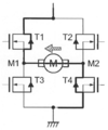
- the transistor T1 and the transistor T4 which are switching elements, are turned on, so that the first terminal M1 of the motor M is energized from the second terminal M2.
- the dead time St12 as shown in FIG. 10B, a current passing from the first terminal M1 to the second terminal M2 by the internal power generation action of the motor M is observed.
- the current shown in FIG. 10B flows from the ground region to the positive side of the battery via the freewheeling diodes of the transistors T2 and T3.
- the transistor T2 and the transistor T3, which are switching elements, are turned on to energize the first terminal M1 from the second terminal M2 of the motor M.
- a current from the second terminal M2 to the first terminal M1 is observed by the internal power generation action of the motor M.
- the current shown in FIG. 10B flows from the ground region to the positive electrode side of the battery via the freewheeling diodes of the transistors T1 and T4.
- FIG. 11 shows an example of the energization waveform during surge elimination energization shown in FIG.
- a phenomenon of counter electromotive force in which a current having a polarity opposite to that applied to the motor M is observed at the dead times St12 and St14. Due to the counter electromotive force at the dead time St12, torque opposite to that at the time of CW energization St11 is generated on the output shaft of the motor M, and torque ripple is generated such that the rotation of the output shaft of the motor vibrates unintentionally.
- the present disclosure has been made in view of the above, and an object of the present disclosure is to provide a motor control device and a motor control program that can eliminate a surge while suppressing torque fluctuation of the output shaft of the motor.
- a motor control device includes a drive unit that supplies a drive voltage to the motor to rotate the motor in a predetermined direction and a direction opposite to the predetermined direction, and a circuit including the drive unit.
- a voltage detection unit that detects the voltage of the motor, and when the voltage detection unit detects a voltage that is equal to or higher than a threshold voltage when the motor is not driven and the supply of the drive voltage to the motor
- a control unit that performs voltage drop control on the drive unit to drop the voltage of the circuit by stopping in a predetermined manner.
- this motor control device while supplying a drive voltage for rotating the motor in a predetermined direction and in a direction opposite to the predetermined direction and stopping the supply in a predetermined manner, torque fluctuation of the output shaft of the motor is suppressed. Surge can be eliminated by lowering the circuit voltage.
- the motor control device is the motor control device according to the first aspect, wherein the drive unit includes a plurality of switching elements, and generates the drive voltage according to an on / off state of the plurality of switching elements,
- the control unit includes a first voltage supply section for rotating the motor in a predetermined direction by on / off control of the plurality of switching elements, and a first voltage stop section for stopping a voltage supplied to the motor after the first voltage supply section.
- a second voltage supply section for rotating the motor in a direction opposite to the predetermined direction after the first voltage stop section, and a second voltage stop section for stopping the voltage supplied to the motor after the second voltage supply section.
- the drive unit is controlled so that the voltage drop control with a period is executed for at least one period.
- this motor control device After the voltage generation for rotating the motor in a predetermined direction, the phenomenon of the counter electromotive force occurs in the motor, but the voltage generation is stopped by turning off all the switching elements following the voltage generation. To eliminate the current generated by the back electromotive force. After eliminating the current generated by the counter electromotive force, a voltage that rotates the motor in the reverse direction of the specified direction is generated and applied to the terminal of the winding of the motor, so surge is suppressed while suppressing torque fluctuation of the motor output shaft. Can be eliminated.
- the current generated by the counter electromotive force is eliminated by turning off all switching elements again and stopping the voltage generation. Surge can be eliminated while suppressing torque fluctuation.
- a motor control device is the motor control device according to the second aspect, wherein the switching element is a field effect transistor in which a free-wheeling diode is connected between a source and a drain, and the control unit
- the plurality of switching elements that generate a voltage for rotating the motor in the predetermined direction in the plurality of switching elements in the supply section are on, the plurality of switching elements are all off in the first voltage stop section, and the second A plurality of switching elements for generating a voltage for rotating the motor in the plurality of switching elements in a direction opposite to the predetermined direction in the voltage supply period are on, and the plurality of switching elements are all off in the second voltage stop period.
- the voltage drop control is executed so that
- the first voltage supply section, the first voltage stop section, the second voltage supply section, and the second voltage stop section are obtained by using a field effect transistor that can be easily controlled to be turned on and off as the switching element. Each control can be easily executed.
- a motor control device is the motor control device according to the second or third aspect, wherein the first voltage stop interval and the second voltage stop interval are between the first voltage supply interval and the first voltage stop interval. Dead time intervals are provided between the voltage supply interval and between the second voltage supply interval and the second voltage stop interval.
- the switching connected in series when the polarity of the voltage generated by the drive unit is switched by setting the dead time to turn off all the switching elements after the section for supplying the voltage to the motor. It is possible to prevent the elements from being turned on simultaneously.
- the motor control device is the motor control device according to any one of the second to fourth aspects, wherein the time of the first voltage stop section is generated inside the motor after the first voltage supply section. And a time during which the current flowing through the motor and the drive unit can be eliminated via the return diodes of the plurality of switching elements, and the time during the second voltage stop period is after the second voltage supply period. This is a time during which current generated in the motor and flowing to the motor and the drive unit via the return diodes of the plurality of switching elements can be eliminated.
- torque fluctuation of the output shaft of the motor can be suppressed by stopping the voltage supply to the motor within a time when the current due to the counter electromotive force can be eliminated.
- a motor control device is the motor control device according to any one of the second to fifth aspects, wherein the control unit performs control at a predetermined control cycle, and the voltage drop control is performed at the start of one control cycle. The execution of one cycle of the voltage drop control is completed together with the end of the one control cycle.
- the voltage drop control can be executed in synchronization with the control cycle.
- a motor control device is the motor control device according to the sixth aspect, wherein the control unit is configured to divide the control cycle of one into four equal parts and set the first voltage supply section, Control of each of the first voltage stop period, the second voltage supply period, and the second voltage stop period is performed on the driving unit.
- the time distribution of each step of the voltage drop control can be easily set by dividing the control period equally and assigning each step of the voltage drop control.
- the motor control device is the motor control device according to any one of the second to seventh aspects, wherein the control unit is in a state in which the motor is not driven and is equal to or higher than a threshold voltage by the voltage detection unit. When the voltage is detected, the voltage drop control is executed at the start of the next control cycle.
- This motor control device can execute voltage drop control according to the main timer.
- a motor control device is the motor control device according to any one of the second to seventh aspects, wherein the control unit is in a state in which the motor is not driven and the voltage detection unit exceeds the threshold voltage. When a voltage is detected, the voltage drop control is immediately executed by interrupt processing.
- a motor control program causes a computer to generate a driving voltage for rotating a motor in a predetermined direction and in a direction opposite to the predetermined direction, and to drive the motor.
- the circuit including the drive unit by supplying the drive voltage to the motor and stopping the supply in a predetermined manner when the voltage detection unit detects a voltage equal to or higher than the threshold voltage.
- a voltage drop control for dropping the voltage is caused to function as a control unit that executes the drive unit.
- the motor control program while supplying a drive voltage for rotating the motor in a predetermined direction and in a direction opposite to the predetermined direction and stopping the supply in a predetermined manner, torque fluctuation of the output shaft of the motor is suppressed. Surge can be eliminated by lowering the circuit voltage.
- the motor control program according to an eleventh aspect is the motor control program according to the tenth aspect, wherein the voltage drop control is a first voltage for rotating the motor in a predetermined direction by on / off control of a plurality of switching elements of the drive unit.
- a first voltage stop period for stopping the voltage supplied to the motor after the first voltage supply period a second voltage supply period for rotating the motor in a direction opposite to the predetermined direction after the first voltage stop period,
- the second voltage stop section in which the voltage supplied to the motor is stopped after the second voltage supply section is set as one cycle, and the drive unit is controlled to execute the voltage drop control for at least one cycle.
- this motor control program after the voltage generation for rotating the motor in a predetermined direction, the phenomenon of back electromotive force occurs in the motor, but after the voltage generation, all switching elements are turned off to stop the voltage generation.
- To eliminate the current generated by the back electromotive force After eliminating the current generated by the counter electromotive force, a voltage that rotates the motor in the reverse direction of the specified direction is generated and applied to the terminal of the winding of the motor, so surge is suppressed while suppressing torque fluctuation of the motor output shaft. Can be eliminated.
- the current generated by the counter electromotive force is eliminated by turning off all the switching elements again to stop the voltage generation.
- the surge can be eliminated while suppressing the torque fluctuation of the motor output shaft.
- a motor control program is the motor control program according to the eleventh aspect, wherein the switching element is a field effect transistor in which a free-wheeling diode is connected between a source and a drain.
- the plurality of switching elements that generate a voltage for rotating the motor in the predetermined direction in the plurality of switching elements in the voltage supply period are on, and the plurality of switching elements are all off in the first voltage stop period.
- the plurality of switching elements for generating a voltage for rotating the motor in the plurality of switching elements in the direction opposite to the predetermined direction in the two voltage supply sections are on, and the plurality of switching elements are all in the second voltage stop section.
- the first voltage supply section, the first voltage stop section, the second voltage supply section, and the second voltage stop section are obtained by using a field effect transistor that can be easily controlled to be turned on and off as the switching element. Each control can be easily executed.
- a motor control program according to a thirteenth aspect is the motor control program according to the eleventh or twelfth aspect, wherein the first voltage stop section and the second voltage stop section are between the first voltage supply section and the first voltage stop section. Dead time intervals are provided between the voltage supply interval and between the second voltage supply interval and the second voltage stop interval.
- this motor control program switching is performed in series when the polarity of the voltage generated by the drive unit is switched by setting the dead time to turn off all switching elements after the section for supplying voltage to the motor. It is possible to prevent the elements from being turned on simultaneously.
- the motor control program according to a fourteenth aspect is the motor control program according to any one of the eleventh to thirteenth aspects, wherein the time of the first voltage stop period is generated inside the motor after the first voltage supply period. And a time during which the current flowing through the motor and the drive unit can be eliminated via the return diodes of the plurality of switching elements, and the time during the second voltage stop period is after the second voltage supply period. This is a time during which current generated in the motor and flowing to the motor and the drive unit via the return diodes of the plurality of switching elements can be eliminated.
- torque fluctuation of the output shaft of the motor can be suppressed by stopping the voltage supply to the motor within a time when the current due to the counter electromotive force can be eliminated.
- the motor control program according to a fifteenth aspect is the motor control program according to any one of the eleventh to fourteenth aspects, wherein one cycle of the voltage drop control is started with the start of one control cycle of the computer, Execution is completed at the end of the one control cycle.
- one cycle of voltage drop control is executed in accordance with the start and end of one control cycle, so that the voltage drop control can be executed in synchronization with the control cycle.
- the motor control program according to a sixteenth aspect is the motor control program according to the fifteenth aspect, wherein the voltage drop control is performed in each time zone set by dividing one control cycle into four equal parts, Control of each of the first voltage stop period, the second voltage supply period, and the second voltage stop period is executed.
- the time distribution of each stage of voltage drop control can be easily set by dividing the control period into approximately equal parts and assigning each stage of voltage drop control.
- a motor control program is the motor control program according to any one of the eleventh to sixteenth aspects, wherein the motor is not driven during the current control cycle and the voltage detection unit When the voltage is detected, the voltage drop control is executed with the start of the next control cycle.
- the motor control program according to an eighteenth aspect is the motor control program according to any one of the eleventh to sixteenth aspects, wherein the voltage detection unit detects a voltage not lower than a threshold voltage when the motor is not driven. In this case, the voltage drop control is immediately executed by interrupt processing.
- mode of the surge elimination energization performed by 1 control period of the microcomputer of the motor control apparatus which concerns on embodiment of this indication is shown.
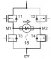
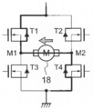
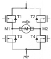
- An example of current generated in the switching element and the motor 18 by CW energization is shown.
- An example of the current generated in the switching element and the motor 18 by the dead time is shown.
- An example of the current generated in the switching element and the motor 18 when the energization is stopped is shown.
- An example of the current generated in the switching element and the motor 18 by the dead time is shown.
- An example of current generated in the switching element and the motor by CCW energization is shown.
- An example of current generated in the switching element and the motor due to dead time is shown.
- An example of the current generated in the switching element and the motor by stopping energization is shown.
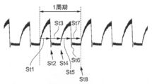
- An example of current generated in the switching element and the motor due to dead time is shown. It shows an example of a waveform of energization at the time of surge elimination energization shown in FIG.
- An aspect of surge elimination energization performed in one control cycle of the control circuit is shown.
- FIG. 10 shows an example of an energization waveform during surge elimination energization shown in FIG. 9.
- FIG. 1 is a schematic diagram illustrating an example of a configuration of a wiper device 100 including a motor control device 10 according to the present embodiment.
- the wiper device 100 is for wiping the windshield glass 12 provided in a vehicle such as a passenger car, for example, and a pair of wipers 14 and 16, a motor 18, a link mechanism 20, and a motor control device 10. And.
- the wipers 14 and 16 are composed of wiper arms 24 and 26 and wiper blades 28 and 30, respectively.
- the base end portions of the wiper arms 24 and 26 are respectively fixed to pivot shafts 42 and 44 described later, and the wiper blades 28 and 30 are respectively fixed to the distal end portions of the wiper arms 24 and 26.
- the wiper blades 28 and 30 reciprocate on the windshield glass 12 as the wiper arms 24 and 26 operate, and the wiper blades 28 and 30 wipe the windshield glass 12.
- the motor 18 has an output shaft 32 that can rotate forward and backward via a speed reduction mechanism 52 mainly composed of a worm gear.
- the link mechanism 20 includes a crank arm 34, a first link rod 36, a pair of pivot levers 38 and 40, a pair of pivot shafts 42 and 44, and a second link rod 46.
- crank arm 34 is fixed to the output shaft 32, and the other end side of the crank arm 34 is operably connected to one end side of the first link rod 36.
- the other end side of the first link rod 36 is operatively connected to a position near the end different from the end having the pivot shaft 42 of the pivot lever 38, and the end of the pivot lever 38 having the pivot shaft 42 is connected to the end of the first link rod 36.
- Both ends of the second link rod 46 are operably connected to different ends and the end of the pivot lever 40 corresponding to the end of the pivot lever 38.
- pivot shafts 42 and 44 are operatively supported by a pivot holder provided on the vehicle body, and ends of the pivot levers 38 and 40 having the pivot shafts 42 and 44 are wiper arms via the pivot shafts 42 and 44. 24 and 26 are respectively fixed.
- the wiper device 100 including the motor control device 10 according to the present embodiment
- the rotational force of the output shaft 32 is transmitted via the link mechanism 20.
- the wiper blades 28 and 30 are reciprocated between the lower reversal position P2 and the upper reversal position P1 on the windshield glass 12 as the wiper arms 24 and 26 are reciprocated.
- the value of ⁇ 1 may take various values depending on the configuration of the link mechanism of the wiper apparatus 100, but is 140 ° as an example in the present embodiment.
- the crank arm 34 and the first link rod 36 is a linear configuration.
- the storage position P3 is provided below the lower inversion position P2.
- the wiper blades 28 and 30 are moved to the retracted position P3 by rotating the output shaft 32 by ⁇ 2 from the state where the wiper blades 28 and 30 are in the lower inversion position P2.
- the value of ⁇ 2 can take various values depending on the configuration of the link mechanism of the wiper device, etc., but in this embodiment, it is 10 ° as an example.
- the motor 18 is connected to a motor control device 10 for controlling the rotation of the motor 18.
- the motor control device 10 controls the rotation speed of the motor 18 based on the detection result of the rotation angle sensor 54 that detects the rotation speed and rotation angle of the output shaft 32 of the motor 18.
- the rotation angle sensor 54 is provided in the speed reduction mechanism 52 of the motor 18 and detects a magnetic field (magnetic force) of a sensor magnet that rotates in conjunction with the output shaft 32 by converting it into a current.
- the rotation speed and rotation angle of the output shaft 32 are not the same as the rotation speed and rotation angle of the wiper motor main body.
- the rotational speed and rotational angle of the output shaft 32 are hereinafter regarded as the rotational speed and rotational angle of the motor 18. .
- the motor control device 10 can calculate the position of the wiper blades 28 and 30 on the windshield glass 12 from the rotation angle of the output shaft 32 detected by the rotation angle sensor 54, and the rotation speed of the output shaft 32 depends on the position.
- the rotational speed of the motor 18 is controlled so as to change.
- the motor control device 10 is connected to a wiper switch 50 that turns on or off the electric power supplied to the motor 18 from a vehicle battery as a power source.
- the wiper switch 50 includes a low-speed operation mode selection position for operating the wiper blades 28 and 30 at a low speed, a high-speed operation mode selection position for operation at a high speed, an intermittent operation mode selection position for intermittent operation at a constant period, and storage (stop).
- the mode selection position can be switched. Further, a command signal for a rotational speed corresponding to the selected position in each mode is output to the motor control device 10.
- the motor control device 10 When a signal output from the wiper switch 50 according to the selected position of each mode is input to the motor control device 10, the motor control device 10 performs using control corresponding to the output signal from the wiper switch 50.
- FIG. 2 is a block diagram illustrating an example of a schematic configuration of the motor control device 10 according to the present embodiment. Moreover, the motor 18 shown in FIG. 2 is a DC motor with a brush as an example.
- the motor control device 10 shown in FIG. 2 includes a drive circuit 56 that generates a voltage to be applied to the winding terminal of the motor 18, a microcomputer 58 that controls on and off of the switching elements that constitute the drive circuit 56, Is included.
- the drive circuit 56 is an example of a drive unit.
- the power of the battery 80 is supplied to the microcomputer 58 via the diode 68, and the voltage of the supplied power is detected by a voltage detection circuit 60 provided between the diode 68 and the microcomputer 58.
- the detection result is output to the microcomputer 58.
- the voltage detection circuit 60 is an example of a voltage detection unit.
- an electrolytic capacitor C1 having one end connected between the diode 68 and the microcomputer 58 and the other end ( ⁇ ) grounded is provided.
- the electrolytic capacitor C1 is a capacitor for stabilizing the power supply of the microcomputer 58.
- the electrolytic capacitor C1 protects the microcomputer 58 by storing a sudden high voltage such as a surge and bypassing it
- the microcomputer 58 receives a signal for instructing the rotational speed of the motor 18 from the wiper switch 50 via the signal input circuit 62. Since the signal output from the wiper switch 50 is an analog signal, the signal is digitized by the signal input circuit 62 and input to the microcomputer 58.
- the microcomputer 58 is connected to a rotation angle sensor 54 that detects a magnetic field of the sensor magnet 70 that changes in accordance with the rotation of the output shaft 32.
- the microcomputer 58 specifies the position of the wiper blades 28 and 30 on the windshield glass 12 by calculating the rotation angle of the output shaft based on the signal output from the rotation angle sensor 54.
- the microcomputer 58 refers to the rotation speed data of the motor 18 defined according to the position of the wiper blades 28 and 30 stored in the memory 48, and the rotation of the motor 18 determines the specified wiper blade 28. , The drive circuit 56 is controlled so that the number of rotations corresponds to the position of 30.
- the drive circuit 56 uses transistors T1, T2, T3, and T4 that are N-type FETs (field effect transistors) as switching elements.
- the drains of the transistors T1 and T2 are connected to the battery 80 via the noise prevention coil 66, and the sources are connected to the drains of the transistors T3 and T4, respectively.
- the sources of the transistors T3 and T4 are grounded.
- the source of the transistor T1 and the drain of the transistor T3 are connected to one end of the winding of the motor 18, and the source of the transistor T2 and the drain of the transistor T4 are connected to the other end of the winding of the motor 18. .
- the transistors T1 and T4 When a high level signal is input to the gates of the transistors T1 and T4, the transistors T1 and T4 are turned on, and the motor 18 rotates, for example, in the clockwise direction when the wiper blades 28 and 30 are viewed from the passenger compartment side.
- An operating CW current 72 flows. Further, when one of the transistor T1 and the transistor T4 is on-controlled, the voltage of the CW current 72 can be modulated by performing on-off control of the other by PWM (Pulse Width Modulation) control.
- PWM Pulse Width Modulation
- a reverse connection protection circuit 64 and a noise prevention coil 66 are provided between the battery 80 as a power source and the drive circuit 56, and the electrolytic capacitor C ⁇ b> 2 is parallel to the drive circuit 56. Is provided.
- the noise prevention coil 66 is an element for suppressing noise generated by switching of the drive circuit 56.
- the electrolytic capacitor C2 relieves noise generated from the drive circuit 56, stores a sudden high voltage such as a surge, and bypasses it to the ground region, so that an excessive current is input to the high voltage drive circuit 56. This is an element for preventing this.
- the reverse connection protection circuit 64 is a circuit for protecting elements constituting the motor control device 10 when the positive electrode and the negative electrode of the battery 80 are connected in reverse to the case shown in FIG.
- the reverse connection protection circuit 64 is configured by a so-called diode-connected FET or the like in which its drain and gate are connected.
- FIG. 3 shows one mode of surge elimination energization performed in one control cycle of the microcomputer 58 of the motor control apparatus 10 according to the present embodiment.
- the supply of drive voltage to the motor 18 for rotating the motor 18 in a predetermined direction and the direction opposite to the predetermined direction and the stop of the supply are performed in a predetermined manner.
- an energization stop St3 that continues energization off for a predetermined time is performed after a dead time St2 that turns off energization.
- CCW energization St5 for reversely rotating the motor 18 is performed, and then a dead time St6 for turning off the energization is provided.
- a dead time St6 for turning off the energization is provided.
- an energization stop St7 that continues energization off for a predetermined time is performed, and then a dead time St8 is executed.
- Each of the dead times St2, St4, St6, and St8 is generally associated with the control of the microcomputer 58, which is a control circuit, and is a process of turning off the energization in an extremely short time in units of milliseconds.
- the motor control device 10 drives the motor 18. It is done when not letting. Even if a surge occurs, if the motor 18 is rotating, the overvoltage due to the surge is consumed by the rotation of the rotating motor 18, and the risk of damaging elements constituting the circuit is reduced.
- the wiper switch 50 When the motor control device 10 does not generate a voltage for driving the motor 18 in the drive circuit 56, the wiper switch 50 is typically turned off, but the present invention is not limited to this. Even if the wiper switch 50 is on, the motor 18 temporarily stops rotating at the position where the wiper blades 28 and 30 are reversed. This is included in the case where the drive circuit 56 does not generate a voltage for driving the circuit 18.
- FIG. 4A shows an example of current generated in the switching element and the motor 18 in each case of CW energization St1, FIG. 4B in dead time St2, FIG. 4C in energization stop St3, and FIG. 4D in dead time St4.
- the transistor T1 and the transistor T4 which are switching elements, are turned on to energize the first terminal M1 of the motor 18 to the second terminal M2.
- the dead time St2 as shown in FIG. 4B, a current from the first terminal M1 to the second terminal M2 is observed by the internal power generation action of the motor 18.
- the current shown in FIG. 4B flows from the ground region to the positive side of the battery via the freewheeling diodes of the transistors T2 and T3.
- FIG. 4C shows a state at the dead time St4, but since the current due to the internal power generation action of the motor 18 is eliminated at the energization stop St3, the current is not observed even at the dead time St4.
- FIG. 5A shows an example of current generated in the switching element and the motor 18 in each case of CCW energization St5
- FIG. 5B is dead time St6
- FIG. 5C is energization stop St7
- FIG. 5D is dead time St8.
- the transistor T2 and the transistor T3, which are switching elements, are turned on, so that the first terminal M1 is energized from the second terminal M2 of the motor 18.
- a current from the second terminal M2 to the first terminal M1 is observed by the internal power generation action of the motor 18.
- the current shown in FIG. 5B flows from the ground region to the positive side of the battery via the freewheeling diodes of the transistors T1 and T4.
- FIG. 5C shows the state at the dead time St8, but since the current due to the internal power generation action of the motor 18 is eliminated at the energization stop St7, the current is not observed even at the dead time St8.
- CW energization St1 and the CCW energization St5 are energization for eliminating the surge, each energization needs to be continued for a certain period of time. However, since it is also necessary to prevent the user from being aware that the motor 18 is operating, it is not recommended to make the energization time longer. In the present embodiment, it is desirable that CW energization St1 and CCW energization St5 each have a short time in units of m seconds.
- the energization stops St3 and St7 are desirably times that can eliminate the current generated by the internal power generation of the motor 18.
- the energization stops St3 and St7 are longer than the CW energization St1 and the CCW energization St5, it is difficult to eliminate the surge. .
- the current due to the internal power generation action of the motor 18 is eliminated by executing the energization stops St3 and St7 at the same time as each of the CW energization St1 and the CCW energization St5.
- CW energization St1, energization stop St3, CCW energization St5 is set in each time zone set by dividing one control cycle of the microcomputer 58 into four equal parts with the dead times St2, St4, St6 interposed therebetween.
- the energization stop St7 is distributed.
- Each unit of surge elimination processing is stored in the microcomputer by storing surge elimination processing that constitutes one cycle including CW energization St1, energization stop St3, CCW energization St5, and energization stop St7 within one control cycle of the microcomputer 58. It can be executed in synchronization with 58 control cycles. For example, the execution of one cycle of the surge elimination process is started with the start of one control cycle, and the completion of the execution of the one cycle of the surge elimination process with the end of the one control cycle is possible. Thereafter, the surge elimination processing can be executed in synchronization with the start of a new control cycle. In the present embodiment, the surge elimination process is executed for at least one cycle to eliminate the high voltage due to the surge.
- the timing control of the start of surge elimination processing is performed using the main timer of the microcomputer 58 as an example. If the main timer is used, if a surge occurs within the current control cycle, the execution of one cycle of the surge elimination process is started simultaneously with the start of the next control cycle.
- the microcomputer 58 has a timer other than the main timer and so-called interrupt processing is possible, when the surge is detected, the surge cancellation processing can be immediately executed by the interrupt processing, and the circuit can be quickly It becomes possible to protect. Even when interrupt processing is executed, each unit of surge cancellation processing can be executed in synchronization with the timer related to interrupt processing by storing one cycle of surge cancellation processing in one control cycle of the timer related to interrupt processing. It becomes possible.
- FIG. 6 shows an example of an energization waveform during surge elimination energization shown in FIG.
- a phenomenon of counter electromotive force in which a current having a polarity opposite to that of the energization of the motor 18 is observed.
- the phenomenon of the counter electromotive force is eliminated by the energization stop St3, and no current having the opposite polarity to the energization of the motor 18 as in the dead time St2 is observed at the dead time St4.
- FIG. 7 is a flowchart showing an example of surge elimination energization control of the motor control device 10 according to the present embodiment.
- step 600 it is determined whether or not a surge has occurred.
- the voltage change is detected by the voltage detection circuit 60 shown in FIG. If the voltage detected by the voltage detection circuit 60 is equal to or higher than the threshold voltage, an affirmative determination is made in step 600 that a surge has occurred.
- the threshold voltage should be set low if priority is given to circuit protection. However, if the threshold voltage is set too low, surge elimination energization control may be frequently executed. Determine the optimal value according to the specifications.
- step 600 determines whether the determination at step 600 is affirmative. If the determination at step 600 is affirmative, a surge elimination process is executed at step 602. In step 604, if the voltage detected by the voltage detection circuit 60 is less than the threshold voltage, an affirmative determination is made, and the process ends. If the determination in step 604 is negative, the procedure returns to step 602, and the surge elimination processing in step 602 is continued.
- FIG. 8 is a flowchart showing an example of surge elimination processing in step 602 of FIG.
- step 700 CW energization St1 is performed, and in step 702, all switching elements are turned off due to dead time St2.
- step 704 energization stop St3 for turning off all the switching elements for a predetermined time is executed.
- step 706 CCW energization St5 is performed in step 708, and in step 710, all switching elements are turned off by dead time St6.
- step 712 energization stop St7 for turning off all the switching elements for a predetermined time is executed, and the process is returned after the dead time St8 in step 714.
- the back-off occurs by executing the energization stop St3 for turning off all the switching elements after the CW energization St1 and the energization stop St7 for turning off all the switching elements after the CCW energization St5. Eliminates the power phenomenon. If the current related to the counter electromotive force does not remain in the motor 18 and the drive circuit 56, the CCW energization St5 having the opposite polarity to the CW energization St1 after the CW energization St1 is performed on the output shaft of the motor 18. Torque fluctuation is less likely to occur.
- the motor control device 10 capable of avoiding element damage due to surge can be manufactured at low cost.
- the control program is stored in the memory 48, for example, and the CPU (Central Processing Unit) of the microcomputer 58 is loaded from the memory 48 and executed, whereby the CPU of the microcomputer 58 functions as a control unit.
- the control program may be stored in a non-transitory storage medium such as a CD-ROM or DVD and loaded into the memory 48, for example.
Landscapes
- Engineering & Computer Science (AREA)
- Power Engineering (AREA)
- Mechanical Engineering (AREA)
- Control Of Direct Current Motors (AREA)
- Stopping Of Electric Motors (AREA)
Abstract
モータを所定方向及び前記所定方向と反対方向に回転させる駆動電圧を前記モータに供給する駆動部と、前記駆動部を含む回路の電圧を検出する電圧検出部と、前記モータを駆動させていない状態でかつ前記電圧検出部により閾値電圧以上の電圧が検出された場合に、前記モータへの前記駆動電圧の供給及び該供給の停止を所定の様式で行うことにより前記回路の電圧を降下させる電圧降下制御を前記駆動部に対して実行する制御部と、を含むモータ制御装置。
Description
本開示は、モータ制御装置及びモータ制御プログラムに関する。
ウィンドシールドガラスをワイパブレードで払拭するワイパ装置は、車両のバッテリから電力の供給を受けて回転するワイパモータにより、ワイパアームの先端に取り付けられたワイパブレードを動作させている。しかしながら、バッテリから供給される電力には、突発的に電圧が高くなるサージが発生する場合がある。サージは、ワイパ装置の回路を構成するコンデンサ及び集積回路等の素子の耐圧を超える電圧になることがあり、かかる場合には、回路を構成する素子が破損するおそれがある。
サージが発生した場合でも、モータが回転していれば、サージによる過電圧はモータの回転によって費やされ、回路を構成する素子が破損するリスクは少なくなる。しかしながら、ワイパモータは、ワイパブレードが反転する位置で一時的に回転を停止するので、サージをモータの回転で費やすことができない場合があり、回路を構成する素子が高電圧によって損傷するおそれがあった。
サージ対策用のツェナーダイオードを回路に付加することにより、サージを解消できる場合があるが、高電圧かつ大電流に対応可能なツェナーダイオードは一般に高価であり、製品の製造コストが嵩むおそれがあった。
特開2015-205574号公報には、ワイパモータ(以下、「モータ」と略記)をm秒単位の微小な間隔で正回転及び逆回転させるように、モータの巻線の端子に通電することにより、サージによる過電圧を解消する制御が開示されている。
図9は、モータを微小な間隔で正回転及び逆回転させるための通電の一態様を示している。図9は、制御回路の1制御周期で行われるサージ解消通電の一態様を示している。図9では、モータを正回転させるCW通電St11が行われた後に、通電をオフにするデッドタイムSt12を経て、ワイパモータを逆回転させるCCW通電St13が行われた後、通電をオフにするデッドタイムSt14が設けられている。デッドタイムSt12、St14は、バッテリの正極(B端子)側と接地領域との間に、直列に接続されたスイッチング素子が同時にオンになることを防止して、当該スイッチング素子を保護するためのものである。
しかしながら、デッドタイムSt12、St14は、m秒単位以下の極短時間であるため、CW通電St11、CCW通電St13による影響を完全に排除することが困難である。図10AはCW通電St11、図10BはデッドタイムSt12、図10CはCCW通電St13、図10DはデッドタイムSt14、の各々の場合でスイッチング素子とモータMとに生じる電流の一例を示している。
図10Aに示したように、CW通電St11では、スイッチング素子であるトランジスタT1及びトランジスタT4が各々オンになることで、モータMの第1端子M1から第2端子M2に通電される。デッドタイムSt12では、図10Bに示したようにモータMの内部発電作用で第1端子M1から第2端子M2に通じる電流が観測される。図10Bに示した電流は、トランジスタT2及びトランジスタT3の各々の還流ダイオードを介して接地領域からバッテリの正極側に流れる。
また、図10Cに示したように、CCW通電St13では、スイッチング素子であるトランジスタT2及びトランジスタT3が各々オンになることで、モータMの第2端子M2から第1端子M1に通電される。デッドタイムSt14では、図10Dに示したようにモータMの内部発電作用で第2端子M2から第1端子M1に通じる電流が観測される。図10Bに示した電流は、トランジスタT1及びトランジスタT4の各々の還流ダイオードを介して接地領域からバッテリの正極側に流れる。
問題は、デッドタイムSt12、St14で各々観測されるモータMの内部発電作用による電流である。図11は、図9に示したサージ解消通電時の通電の波形の一例を示したものである。図11に示したように、デッドタイムSt12、St14で、モータMへの通電とは逆極性の電流が生じる逆起電力の現象が観測される。デッドタイムSt12での逆起電力により、モータMの出力軸にはCW通電St11時とは逆のトルクが生じ、モータの出力軸の回転が意に反して振動するようなトルクリップルが生じる。かかる状態でCW通電St11とは逆方向のCCW通電St13を行うと、モータMの出力軸のトルクリップルはさらに顕著になり、ユーザに当該トルクリップルに起因する音及び振動を覚知されるおそれがあった。
本開示は上記に鑑みてなされたもので、モータの出力軸のトルク変動を抑制しつつサージを解消できるモータ制御装置及びモータ制御プログラムを提供することを目的とする。
前記課題を解決するために、第1の態様のモータ制御装置は、モータを所定方向及び前記所定方向と反対方向に回転させる駆動電圧を前記モータに供給する駆動部と、前記駆動部を含む回路の電圧を検出する電圧検出部と、前記モータを駆動させていない状態でかつ前記電圧検出部により閾値電圧以上の電圧が検出された場合に、前記モータへの前記駆動電圧の供給及び該供給の停止を所定の様式で行うことにより前記回路の電圧を降下させる電圧降下制御を前記駆動部に対して実行する制御部と、を含んでいる。
このモータ制御装置によれば、モータを所定方向及び当該所定方向と反対方向に回転させる駆動電圧の供給及び該供給の停止を所定の様式で行うことによりモータの出力軸のトルク変動を抑制しつつ回路の電圧を降下させてサージを解消できる。
第2の態様のモータ制御装置は、第1の態様のモータ制御装置において、前記駆動部は、複数のスイッチング素子を備え、前記複数のスイッチング素子のオンオフ状態に応じて前記駆動電圧を生成し、前記制御部は、前記複数のスイッチング素子のオンオフ制御により、前記モータを所定方向に回転させる第1電圧供給区間、前記第1電圧供給区間後に前記モータに供給する電圧を停止する第1電圧停止区間、前記第1電圧停止区間後に前記モータを前記所定方向と反対方向に回転させる第2電圧供給区間、及び前記第2電圧供給区間後に前記モータに供給する電圧を停止する第2電圧停止区間を1周期とする前記電圧降下制御を少なくとも1周期分実行するように前記駆動部を制御する。
このモータ制御装置によれば、モータを所定方向に回転させる電圧生成後に、モータには逆起電力の現象が発生するが、当該電圧生成に後続して全スイッチング素子をオフにして電圧生成の停止を行うことにより逆起電力で生じた電流を解消している。逆起電力で生じた電流を解消した後に、モータを所定方向の逆方向に回転させる電圧を生成してモータの巻線の端子に印加するので、モータの出力軸のトルク変動を抑制しつつサージを解消できる。
また、モータを所定方向の逆方向に回転させる電圧生成後は、再び全スイッチング素子をオフにして電圧生成の停止を行うことにより逆起電力で生じた電流を解消するので、モータの出力軸のトルク変動を抑制しつつサージを解消できる。
第3の態様のモータ制御装置は、第2の態様のモータ制御装置において、前記スイッチング素子は、ソースドレイン間に還流ダイオードが接続された電界効果トランジスタであり、前記制御部は、前記第1電圧供給区間で前記複数のスイッチング素子の中の前記モータを前記所定方向に回転させる電圧を生成させる複数のスイッチング素子がオン、前記第1電圧停止区間で前記複数のスイッチング素子が全てオフ、前記第2電圧供給区間で前記複数のスイッチング素子の中の前記モータを前記所定方向と反対方向に回転させる電圧を生成させる複数のスイッチング素子がオン、前記第2電圧停止区間で前記複数のスイッチング素子が全てオフ、となるように前記電圧降下制御を実行する。
このモータ制御装置によれば、スイッチング素子にオンオフ状態の制御が容易な電界効果トランジスタを用いることにより、第1電圧供給区間、第1電圧停止区間、第2電圧供給区間、及び第2電圧停止区間の各々の制御を容易に実行できる。
第4の態様のモータ制御装置は、第2又は第3の態様のモータ制御装置において、前記第1電圧供給区間と前記第1電圧停止区間との間、前記第1電圧停止区間と前記第2電圧供給区間との間、及び前記第2電圧供給区間と前記第2電圧停止区間との間に、デッドタイム区間を設けている。
このモータ制御装置によれば、電圧をモータに供給する区間後に全スイッチング素子をオフにするデッドタイムを設定することにより、駆動部が生成する電圧の極性が切り換わる際に直列で接続されたスイッチング素子が同時にオンになることを防止できる。
第5の態様のモータ制御装置は、第2~第4のいずれかの態様のモータ制御装置において、前記第1電圧停止区間の時間は、前記第1電圧供給区間後に、前記モータの内部に発生し、前記複数のスイッチング素子の還流ダイオードを介して、前記モータと前記駆動部とに流れる電流を解消し得る時間であり、前記第2電圧停止区間の時間は、前記第2電圧供給区間後に前記モータの内部に発生し、前記複数のスイッチング素子の還流ダイオードを介して、前記モータと前記駆動部とに流れる電流を解消し得る時間である。
このモータ制御装置によれば、逆起電力による電流が解消し得る時間でモータへの電圧供給を停止することにより、モータの出力軸のトルク変動を抑制できる。
第6の態様のモータ制御装置は、第2~第5のいずれかの態様のモータ制御装置において、前記制御部は、所定制御周期で制御を行い、1の制御周期の開始と共に前記電圧降下制御の1周期の実行を開始し、該1の制御周期の終了と共に前記電圧降下制御の1周期の実行を完了する。
このモータ制御装置によれば、1の制御周期の開始と終了に合わせて電圧降下制御の1周期を実行するので、電圧降下制御を制御周期に同期させて実行することができる。
第7の態様のモータ制御装置は、第6の態様のモータ制御装置において、前記制御部は、1の制御周期を4等分して設定した各時間帯で、前記第1電圧供給区間、前記第1電圧停止区間、前記第2電圧供給区間、及び前記第2電圧停止区間の各々の制御を前記駆動部に対し実行する。
このモータ制御装置によれば、制御周期を等分に分割して電圧降下制御の各々の段階を割り振ることにより、電圧降下制御の各々の段階の時間配分を容易に設定することができる。
第8の態様のモータ制御装置は、第2~第7のいずれかの態様のモータ制御装置において、前記制御部は、前記モータを駆動させていない状態でかつ前記電圧検出部により閾値電圧以上の電圧が検出された場合に、次の制御周期の開始と共に前記電圧降下制御を実行する。
このモータ制御装置によれば、メインのタイマに従って、電圧降下制御を実行することができる。
第9の態様のモータ制御装置は、第2~第7のいずれかの態様のモータ制御装置において、前記制御部は、前記モータを駆動させていない状態でかつ前記電圧検出部により閾値電圧以上の電圧が検出された場合に、割り込み処理により前記電圧降下制御を即時実行する。
このモータ制御装置によれば、サージが発生した場合には、割り込み処理により電圧降下制御をただちに実行できるので、回路を迅速に保護することができる。
前記課題を解決するために、第10の態様のモータ制御プログラムは、コンピュータを、モータを所定方向及び前記所定方向と反対方向に回転させる駆動電圧を駆動部に生成させると共に、前記モータを駆動させていない状態でかつ電圧検出部により閾値電圧以上の電圧が検出された場合に、前記モータへの前記駆動電圧の供給及び該供給の停止を所定の様式で行うことにより前記駆動部を含む回路の電圧を降下させる電圧降下制御を前記駆動部に対して実行する制御部として機能させる。
このモータ制御プログラムによれば、モータを所定方向及び当該所定方向と反対方向に回転させる駆動電圧の供給及び該供給の停止を所定の様式で行うことによりモータの出力軸のトルク変動を抑制しつつ回路の電圧を降下させてサージを解消できる。
第11の態様のモータ制御プログラムは、第10の態様のモータ制御プログラムにおいて、前記電圧降下制御は、前記駆動部の複数のスイッチング素子のオンオフ制御により、前記モータを所定方向に回転させる第1電圧供給区間、前記第1電圧供給区間後に前記モータに供給する電圧を停止する第1電圧停止区間、前記第1電圧停止区間後に前記モータを前記所定方向と反対方向に回転させる第2電圧供給区間、及び前記第2電圧供給区間後に前記モータに供給する電圧を停止する第2電圧停止区間を1周期とし、前記電圧降下制御を少なくとも1周期分実行するように前記駆動部を制御する。
このモータ制御プログラムによれば、モータを所定方向に回転させる電圧生成後に、モータには逆起電力の現象が発生するが、当該電圧生成に後続して全スイッチング素子をオフにして電圧生成の停止を行うことにより逆起電力で生じた電流を解消している。逆起電力で生じた電流を解消した後に、モータを所定方向の逆方向に回転させる電圧を生成してモータの巻線の端子に印加するので、モータの出力軸のトルク変動を抑制しつつサージを解消できる。
また、モータを所定方向の逆方向に回転させる電圧生成後は、再び全スイッチング素子をオフにして電圧生成の停止を行うことにより逆起電力で生じた電流を解消するので、その後、モータを所定方向に回転させる電圧を生成してモータの巻線の端子に印加した場合に、モータの出力軸のトルク変動を抑制しつつサージを解消できる。
第12の態様のモータ制御プログラムは、第11の態様のモータ制御プログラムにおいて、前記スイッチング素子は、ソースドレイン間に還流ダイオードが接続された電界効果トランジスタであり、前記電圧降下制御は、前記第1電圧供給区間で前記複数のスイッチング素子の中の前記モータを前記所定方向に回転させる電圧を生成させる複数のスイッチング素子がオン、前記第1電圧停止区間で前記複数のスイッチング素子が全てオフ、前記第2電圧供給区間で前記複数のスイッチング素子の中の前記モータを前記所定方向と反対方向に回転させる電圧を生成させる複数のスイッチング素子がオン、前記第2電圧停止区間で前記複数のスイッチング素子が全てオフ、となる。
このモータ制御プログラムによれば、スイッチング素子にオンオフ状態の制御が容易な電界効果トランジスタを用いることにより、第1電圧供給区間、第1電圧停止区間、第2電圧供給区間、及び第2電圧停止区間の各々の制御を容易に実行できる。
第13の態様のモータ制御プログラムは、第11又は第12の態様のモータ制御プログラムにおいて、前記第1電圧供給区間と前記第1電圧停止区間との間、前記第1電圧停止区間と前記第2電圧供給区間との間、及び前記第2電圧供給区間と前記第2電圧停止区間との間に、デッドタイム区間を設けている。
このモータ制御プログラムによれば、電圧をモータに供給する区間後に全スイッチング素子をオフにするデッドタイムを設定することにより、駆動部が生成する電圧の極性が切り換わる際に直列で接続されたスイッチング素子が同時にオンになることを防止できる。
第14の態様のモータ制御プログラムは、第11~第13のいずれかの態様のモータ制御プログラムにおいて、前記第1電圧停止区間の時間は、前記第1電圧供給区間後に、前記モータの内部に発生し、前記複数のスイッチング素子の還流ダイオードを介して、前記モータと前記駆動部とに流れる電流を解消し得る時間であり、前記第2電圧停止区間の時間は、前記第2電圧供給区間後に前記モータの内部に発生し、前記複数のスイッチング素子の還流ダイオードを介して、前記モータと前記駆動部とに流れる電流を解消し得る時間である。
このモータ制御プログラムによれば、逆起電力による電流が解消し得る時間でモータへの電圧供給を停止することにより、モータの出力軸のトルク変動を抑制できる。
第15の態様のモータ制御プログラムは、第11~第14のいずれかの態様のモータ制御プログラムにおいて、前記電圧降下制御の1周期は、前記コンピュータの1の制御周期の開始と共に実行が開始され、該1の制御周期の終了と共に実行が完了する。
このモータ制御プログラムによれば、1の制御周期の開始と終了に合わせて電圧降下制御の1周期を実行するので、電圧降下制御を制御周期に同期させて実行することができる。
第16の態様のモータ制御プログラムは、第15の態様のモータ制御プログラムにおいて、前記電圧降下制御は、1の制御周期を4等分して設定した各時間帯で、前記第1電圧供給区間、前記第1電圧停止区間、前記第2電圧供給区間、及び前記第2電圧停止区間の各々の制御が実行される。
制御周期を略等分に分割して電圧降下制御の各々の段階を割り振ることにより、電圧降下制御の各々の段階の時間配分を容易に設定することができる。
第17の態様のモータ制御プログラムは、第11~第16のいずれかの態様のモータ制御プログラムにおいて、現制御周期中に前記モータを駆動させていない状態でかつ前記電圧検出部により閾値電圧以上の電圧が検出された場合に、次の制御周期の開始と共に前記電圧降下制御が実行される。
このモータ制御プログラムによれば、メインのタイマに従って、電圧降下制御を実行することができる。
第18の態様のモータ制御プログラムは、第11~第16のいずれかの態様のモータ制御プログラムにおいて、前記モータを駆動させていない状態でかつ前記電圧検出部により閾値電圧以上の電圧が検出された場合に、割り込み処理により前記電圧降下制御が即時実行される。
このモータ制御プログラムによれば、サージが発生した場合には、割り込み処理により電圧降下制御をただちに実行できるので、回路を迅速に保護することができる。
図1は、本実施の形態に係るモータ制御装置10を含むワイパ装置100の構成の一例を示す概略図である。ワイパ装置100は、例えば、乗用自動車等の車両に備えられたウィンドシールドガラス12を払拭するためのものであり、一対のワイパ14、16と、モータ18と、リンク機構20と、モータ制御装置10と、を備えている。
ワイパ14、16は、それぞれワイパアーム24、26とワイパブレード28、30とにより構成されている。ワイパアーム24、26の基端部は、後述するピボット軸42、44に各々固定されており、ワイパブレード28、30は、ワイパアーム24、26の先端部に各々固定されている。
ワイパ14、16は、ワイパアーム24、26の動作に伴ってワイパブレード28、30がウィンドシールドガラス12上を往復動作し、ワイパブレード28、30がウィンドシールドガラス12を払拭する。
モータ18は、主にウォームギアで構成された減速機構52を介して、正逆回転可能な出力軸32を有している。リンク機構20は、クランクアーム34と、第1リンクロッド36と、一対のピボットレバー38、40と、一対のピボット軸42、44と、第2リンクロッド46と、を備えている。
クランクアーム34の一端側は、出力軸32に固定されており、クランクアーム34の他端側は、第1リンクロッド36の一端側に動作可能に連結されている。また、第1リンクロッド36の他端側は、ピボットレバー38のピボット軸42を有する端とは異なる端寄りの箇所に動作可能に連結されており、ピボットレバー38のピボット軸42を有する端とは異なる端及びピボットレバー40におけるピボットレバー38の当該端に対応する端には、第2リンクロッド46の両端がそれぞれ動作可能に連結されている。
また、ピボット軸42、44は、車体に設けられたピボットホルダによって動作可能に支持されており、ピボットレバー38、40におけるピボット軸42、44を有する端は、ピボット軸42、44を介してワイパアーム24、26が各々固定されている。
本実施の形態に係るモータ制御装置10を含むワイパ装置100では、出力軸32が所定の範囲の回転角θ1で正逆回転されると、この出力軸32の回転力がリンク機構20を介してワイパアーム24、26に伝達され、このワイパアーム24、26の往復動作に伴ってワイパブレード28、30がウィンドシールドガラス12上における下反転位置P2と上反転位置P1との間で往復動作をする。θ1の値は、ワイパ装置100のリンク機構の構成等によって様々な値をとり得るが、本実施の形態では、一例として140°である。
本実施の形態に係るモータ制御装置10を含むワイパ装置100では、図1に示されるように、ワイパブレード28、30が格納位置P3に位置された場合には、クランクアーム34と第1リンクロッド36とが直線状をなす構成とされている。
格納位置P3は、下反転位置P2の下方に設けられている。ワイパブレード28、30が下反転位置P2にある状態から、出力軸32がθ2回転することにより、ワイパブレード28、30は格納位置P3に動作する。θ2の値は、ワイパ装置のリンク機構の構成等によって様々な値をとり得るが、本実施の形態では、一例として10°とする。
なお、θ2が「0」の場合は、下反転位置P2と格納位置P3は一致し、ワイパブレード28、30は、下反転位置P2で停止し、格納される。
モータ18には、モータ18の回転を制御するためのモータ制御装置10が接続されている。本実施の形態に係るモータ制御装置10は、モータ18の出力軸32の回転速度及び回転角を検知する回転角度センサ54の検知結果に基づいてモータ18の回転速度を制御する。回転角度センサ54は、モータ18の減速機構52内に設けられ、出力軸32に連動して回転するセンサマグネットの磁界(磁力)を電流に変換して検出する。
本実施の形態に係るモータ18は、前述のように減速機構52を有しているので、出力軸32の回転速度及び回転角は、ワイパモータ本体の回転速度及び回転角と同一ではない。しかしながら、本実施の形態では、ワイパモータ本体と減速機構52は一体不可分に構成されているので、以下、出力軸32の回転速度及び回転角を、モータ18の回転速度及び回転角とみなすものとする。
モータ制御装置10は、回転角度センサ54が検出した出力軸32の回転角からワイパブレード28、30のウィンドシールドガラス12上での位置を算出可能で当該位置に応じて出力軸32の回転速度が変化するようにモータ18の回転速度を制御する。
また、モータ制御装置10には、電源である車両のバッテリからモータ18に供給される電力をオン又はオフするワイパスイッチ50が接続されている。ワイパスイッチ50は、ワイパブレード28、30を、低速で動作させる低速作動モード選択位置、高速で動作させる高速作動モード選択位置、一定周期で間欠的に動作させる間欠作動モード選択位置、格納(停止)モード選択位置に切替可能である。また、各モードの選択位置に応じた回転速度の指令の信号をモータ制御装置10に出力する。
ワイパスイッチ50から各モードの選択位置に応じて出力された信号がモータ制御装置10に入力されると、モータ制御装置10がワイパスイッチ50からの出力信号に対応する制御を用いて行う。
図2は、本実施の形態に係るモータ制御装置10の構成の概略の一例を示すブロック図である。また、図2示したモータ18は、一例として、ブラシ付きDCモータである。
図2に示したモータ制御装置10は、モータ18の巻線の端子に印加する電圧を生成する駆動回路56と、駆動回路56を構成するスイッチング素子のオン及びオフを制御するマイクロコンピュータ58と、を含んでいる。駆動回路56は、駆動部の一例である。マイクロコンピュータ58には、ダイオード68を介してバッテリ80の電力が供給されると共に、供給される電力の電圧は、ダイオード68とマイクロコンピュータ58との間に設けられた電圧検出回路60によって検知され、検知結果はマイクロコンピュータ58に出力される。電圧検出回路60は、電圧検出部の一例である。また、ダイオード68とマイクロコンピュータ58との間に一端が接続され、他端(-)が接地された電解コンデンサC1が設けられている。電解コンデンサC1は、マイクロコンピュータ58の電源を安定化するためのコンデンサである。電解コンデンサC1は、例えば、サージ等の突発的な高電圧を蓄え、接地領域にバイパスすることにより、マイクロコンピュータ58を保護する。
マイクロコンピュータ58には信号入力回路62を介してワイパスイッチ50からモータ18の回転速度を指示するための信号が入力される。ワイパスイッチ50から出力された信号はアナログ信号なので、当該信号は信号入力回路62においてデジタル化されてマイクロコンピュータ58に入力される。
また、マイクロコンピュータ58には、出力軸32の回転に応じて変化するセンサマグネット70の磁界を検知する回転角度センサ54が接続されている。マイクロコンピュータ58は、回転角度センサ54が出力した信号に基づいて、出力軸の回転角度を算出することにより、ワイパブレード28、30のウィンドシールドガラス12上での位置を特定する。
さらに、マイクロコンピュータ58は、メモリ48に記憶されているワイパブレード28、30の位置に応じて規定されたモータ18の回転速度のデータを参照して、モータ18の回転が、特定したワイパブレード28、30の位置に応じた回転数になるように駆動回路56を制御する。
駆動回路56は、図2に示すように、スイッチング素子にN型のFET(電界効果トランジスタ)であるトランジスタT1、T2、T3、T4を用いている。トランジスタT1及びトランジスタT2は、ドレインがノイズ防止コイル66を介してバッテリ80に各々接続されており、ソースがトランジスタT3及びトランジスタT4のドレインに各々接続されている。また、トランジスタT3及びトランジスタT4のソースは接地されている。
また、トランジスタT1のソース及びトランジスタT3のドレインは、モータ18の巻線の一端に接続されており、トランジスタT2のソース及びトランジスタT4のドレインは、モータ18の巻線の他端に接続されている。
トランジスタT1及びトランジスタT4の各々のゲートにハイレベル信号が入力されることにより、トランジスタT1及びトランジスタT4がオンになり、モータ18には例えばワイパブレード28、30を車室側から見て時計回りに動作させるCW電流72が流れる。さらに、トランジスタT1及びトランジスタT4の一方をオン制御しているとき、他方をPWM(Pulse Width Modulation)制御により、小刻みにオンオフ制御することにより、CW電流72の電圧を変調できる。
また、トランジスタT2及びトランジスタT3の各々のゲートにハイレベル信号が入力されることにより、トランジスタT2及びトランジスタT3がオンになり、モータ18には例えばワイパブレード28、30を車室側から見て反時計回りに動作させるCCW電流74が流れる。さらに、トランジスタT2及びトランジスタT3の一方をオン制御しているとき、他方をPWM制御により、小刻みにオンオフ制御することにより、CCW電流74の電圧を変調できる。
本実施の形態では、電源であるバッテリ80と駆動回路56との間には逆接続保護回路64及びノイズ防止コイル66が設けられると共に、駆動回路56に対して並列になるように電解コンデンサC2が設けられている。ノイズ防止コイル66は、駆動回路56のスイッチングによって発生するノイズを抑制するための素子である。
電解コンデンサC2は、駆動回路56から生じるノイズを緩和すると共に、サージ等の突発的な高電圧を蓄え、接地領域にバイパスすることにより、当該高電圧の駆動回路56に過大な電流が入力されるのを防止するための素子である。
逆接続保護回路64は、バッテリ80の正極と負極が図2に示した場合とは逆に接続された場合に、モータ制御装置10を構成する素子を保護するための回路である。逆接続保護回路64は、一例として、自身のドレインとゲートを接続した、いわゆるダイオード接続されたFET等で構成される。
以下、本実施の形態に係るモータ制御装置10の作用及び効果について説明する。図3は、本実施の形態に係るモータ制御装置10のマイクロコンピュータ58の1制御周期で行われるサージ解消通電の一態様を示している。図3に示したように、本実施形態に係るサージ解消通電では、モータ18を所定方向及び当該所定方向と反対方向に回転させる駆動電圧のモータ18への供給及び当該供給の停止を所定の様式で行う。具体的には、モータ18を正回転させるCW通電St1が行われた後に、通電をオフにするデッドタイムSt2を経て、通電オフを所定時間継続する通電停止St3が行われる。
通電停止St3後は、通電をオフにするデッドタイムSt4を経て、モータ18を逆回転させるCCW通電St5が行われた後、通電をオフにするデッドタイムSt6が設けられている。デッドタイムSt6に続いて、通電オフを所定時間継続する通電停止St7が行われた後、デッドタイムSt8が実行される。
デッドタイムSt2、St4、St6、St8の各々は、制御回路であるマイクロコンピュータ58の制御に一般的に付随するもので、m秒単位以下の極短時間で通電をオフにする処理である。
なお、図3に示したサージ解消通電は、モータ18がワイパ装置100のワイパブレード28、30を払拭動作させていない場合、すなわちモータ制御装置10がモータ18を駆動させる電圧を駆動回路56に生成させていない場合に行われる。サージが発生した場合でも、モータ18が回転していれば、サージによる過電圧は回転するモータ18の回転によって費やされ、回路を構成する素子が破損するリスクは少なくなるからである。
モータ制御装置10がモータ18を駆動させる電圧を駆動回路56に生成させていない場合は、ワイパスイッチ50がオフになっている状態が代表的であるが、これに限定されない。ワイパスイッチ50がオンになっていても、モータ18は、ワイパブレード28、30が反転する位置で一時的に回転を停止するので、かかる場合も、短時間ではあるものの、モータ制御装置10がモータ18を駆動させる電圧を駆動回路56に生成させていない場合に含まれる。
図4AはCW通電St1、図4BはデッドタイムSt2、図4Cは通電停止St3、図4DはデッドタイムSt4、の各々の場合でスイッチング素子とモータ18とに生じる電流の一例を示している。
図4Aに示したように、CW通電St1では、スイッチング素子であるトランジスタT1及びトランジスタT4が各々オンになることで、モータ18の第1端子M1から第2端子M2に通電される。デッドタイムSt2では、図4Bに示したようにモータ18の内部発電作用で第1端子M1から第2端子M2に通じる電流が観測される。図4Bに示した電流は、トランジスタT2及びトランジスタT3の各々の還流ダイオードを介して接地領域からバッテリの正極側に流れる。
しかしながら、図4Cに示したように、通電停止St3では、モータ18の内部発電作用による電流が解消されるのに十分な時間で全スイッチング素子がオフになるので、デッドタイムSt2で観測された電流は解消される。図4DはデッドタイムSt4における状態を示しているが、通電停止St3でモータ18の内部発電作用による電流が解消されているので、デッドタイムSt4においても当該電流は観測されない。
図5AはCCW通電St5、図5BはデッドタイムSt6、図5Cは通電停止St7、図5DはデッドタイムSt8、の各々の場合でスイッチング素子とモータ18とに生じる電流の一例を示している。
図5Aに示したように、CCW通電St5では、スイッチング素子であるトランジスタT2及びトランジスタT3が各々オンになることで、モータ18の第2端子M2から第1端子M1に通電される。デッドタイムSt6では、図5Bに示したようにモータ18の内部発電作用で第2端子M2から第1端子M1に通じる電流が観測される。図5Bに示した電流は、トランジスタT1及びトランジスタT4の各々の還流ダイオードを介して接地領域からバッテリの正極側に流れる。
しかしながら、図5Cに示したように、通電停止St7では、モータ18の内部発電作用による電流が解消されるのに十分な時間で全スイッチング素子がオフになるので、デッドタイムSt6で観測された電流は解消される。図5DはデッドタイムSt8における状態を示しているが、通電停止St7でモータ18の内部発電作用による電流が解消されているので、デッドタイムSt8においても当該電流は観測されない。
CW通電St1及びCCW通電St5は、サージを解消するための通電なので、ある程度の時間で通電を各々継続することを要する。しかしながら、ユーザにモータ18が作動していることを覚知されないようにすることも要するので、通電時間を無闇に長くすることは推奨されない。本実施の形態では、CW通電St1及びCCW通電St5は各々m秒単位の短時間であることが望ましい。また、通電停止St3、St7は、モータ18の内部発電作用による電流を解消し得る時間であることが望ましいが、CW通電St1及びCCW通電St5に比して無闇に長くすると、サージの解消がおぼつかない。一例として、CW通電St1及びCCW通電St5の各々と同じ時間で通電停止St3、St7を実行することで、モータ18の内部発電作用による電流を解消する。
本実施の形態では、一例として、マイクロコンピュータ58の1制御周期をデッドタイムSt2、St4、St6を挟んで4等分にして設定した各時間帯に、CW通電St1、通電停止St3、CCW通電St5、通電停止St7を振り分けている。
マイクロコンピュータ58の1制御周期内にCW通電St1、通電停止St3、CCW通電St5、通電停止St7を含んで1周期を構成するサージ解消処理を格納することで、サージ解消処理の各単位をマイクロコンピュータ58の制御周期に同期させて実行できる。例えば、1の制御周期の開始と共にサージ解消処理の1周期の実行を開始し、当該1の制御周期の終了と共にサージ解消処理の当該1周期の実行を完了する制御が可能になる。そして、以後、新たな制御周期の開始に同期させて、サージ解消処理を実行することができる。本実施の形態では、サージ解消処理を少なくとも1周期分実行することにより、サージによる高電圧を解消する。
サージ解消処理の開始のタイミング制御は、一例として、マイクロコンピュータ58のメインのタイマを使用して行う。メインのタイマを使用するのであれば、現制御周期内でサージが発生した場合には、次の制御周期の開始と共にサージ解消処理の1周期の実行を開始する。
また、マイクロコンピュータ58がメインのタイマ以外に別途タイマを有し、いわゆる割り込み処理が可能であれば、サージが検出された場合に当該割り込み処理により、サージ解消処理を即時実行でき、回路を迅速に保護することが可能となる。割り込み処理を実行する場合も、割り込み処理に係るタイマの1制御周期にサージ解消処理の1周期を格納することで、割り込み処理に係るタイマに同期させてサージ解消処理の各単位を実行することが可能となる。
図6は、図3に示したサージ解消通電時の通電の波形の一例を示したものである。図6に示したように、CW通電St1後のデッドタイムSt2で、モータ18への通電とは逆極性の電流が生じる逆起電力の現象が観測される。しかしながら、通電停止St3により逆起電力の現象は解消され、デッドタイムSt4ではデッドタイムSt2のようなモータ18への通電とは逆極性の電流は観測されない。
また、CCW通電St5後のデッドタイムSt6で、モータ18への通電とは逆極性の電流が生じる逆起電力の現象が観測される。しかしながら、通電停止St7により逆起電力の現象は解消され、デッドタイムSt8ではデッドタイムSt6のようなモータ18への通電とは逆極性の電流は観測されない。
本実施の形態では、CW通電St1後のデッドタイムSt2でモータ18の内部発電作用による電流が観測されるが、当該電流は通電停止St3により解消される。かかる状態でCW通電St1とは逆方向のCCW通電St5を行うのであれば、モータMの出力軸にトルクリップルが生じるおそれは少なくなる。
また、CCW通電St5後のデッドタイムSt6でモータ18の内部発電作用による電流が観測されるが、当該電流は通電停止St7により解消される。かかる状態でCCW通電St5とは逆方向のCW通電St1を行うのであれば、モータMの出力軸にトルクリップルが生じるおそれは少なくなる。
図7は、本実施の形態に係るモータ制御装置10のサージ解消通電制御の一例を示したフローチャートである。ステップ600では、サージが発生したか否かを判定する。本実施の形態では、図2に示した電圧検出回路60により、電圧の変化を検知している。電圧検出回路60が検知した電圧が閾値電圧以上の場合には、サージが発生したとして、ステップ600で肯定判定をする。なお、閾値電圧は、回路保護を優先するのであれば、低めに設定するべきであるが、過度に低めに設定すると、頻繁にサージ解消通電制御が実行されるおそれがあるので、ワイパ装置100の仕様等に応じた最適な値を決定する。
ステップ600で肯定判定の場合には、ステップ602でサージ解消処理を実行する。ステップ604では、電圧検出回路60が検知した電圧が閾値電圧未満になった場合には肯定判定を行い、処理を終了する。ステップ604で否定判定の場合には、手順をステップ602に戻し、ステップ602のサージ解消処理を継続する。
図8は、図7のステップ602におけるサージ解消処理の一例を示したフローチャートである。ステップ700ではCW通電St1を行い、ステップ702ではデッドタイムSt2により全スイッチング素子をオフにする。ステップ704では所定時間全スイッチング素子をオフにする通電停止St3を実行する。
ステップ706のデッドタイムSt4に後続してステップ708ではCCW通電St5を行い、ステップ710ではデッドタイムSt6により全スイッチング素子をオフにする。ステップ712では所定時間全スイッチング素子をオフにする通電停止St7を実行し、ステップ714のデッドタイムSt8後に処理をリターンする。
以上説明したように、本実施の形態では、CW通電St1後に全スイッチング素子をオフする通電停止St3と、CCW通電St5後に全スイッチング素子をオフする通電停止St7と、を各々実行することにより逆起電力の現象を解消している。モータ18及び駆動回路56に逆起電力に係る電流が残存していない状態であれば、CW通電St1後にCW通電St1とは逆極性のCCW通電St5を行っても、モータ18の出力軸にはトルク変動が生じにくくなる。また、CCW通電St5後にCCW通電St5とは逆極性のCW通電St1を行う場合も、モータ18の出力軸にトルク変動が生じにくくなる。その結果、モータの出力軸のトルク変動を抑制しつつサージを解消できる。
また、本実施の形態では、一連の制御はマイクロコンピュータ58の制御プログラムを書き換えることで可能なので、サージ解消のために別部品を実装することを要しない。その結果、サージによる素子の損傷を回避できるモータ制御装置10を低コストで製造できる。
制御プログラムは、例えば、メモリ48に記憶され、マイクロコンピュータ58のCPU(Central Processing Unit)がメモリ48からロードして実行することで、マイクロコンピュータ58のCPUは、制御部として機能する。制御プログラムは、例えば、CD-ROM、DVDなどの非一時的記憶媒体に記憶され、メモリ48にロードされてもよい。
2016年3月30日に出願された日本国特許出願2016-068592号の開示は、その全体が参照により本明細書に取り込まれる。
Claims (18)
- モータを所定方向及び前記所定方向と反対方向に回転させる駆動電圧を前記モータに供給する駆動部と、
前記駆動部を含む回路の電圧を検出する電圧検出部と、
前記モータを駆動させていない状態でかつ前記電圧検出部により閾値電圧以上の電圧が検出された場合に、前記モータへの前記駆動電圧の供給及び該供給の停止を所定の様式で行うことにより前記回路の電圧を降下させる電圧降下制御を前記駆動部に対して実行する制御部と、
を含むモータ制御装置。 - 前記駆動部は、複数のスイッチング素子を備え、前記複数のスイッチング素子のオンオフ状態に応じて前記駆動電圧を生成し、
前記制御部は、前記複数のスイッチング素子のオンオフ制御により、前記モータを所定方向に回転させる第1電圧供給区間、前記第1電圧供給区間後に前記モータに供給する電圧を停止する第1電圧停止区間、前記第1電圧停止区間後に前記モータを前記所定方向と反対方向に回転させる第2電圧供給区間、及び前記第2電圧供給区間後に前記モータに供給する電圧を停止する第2電圧停止区間を1周期とする前記電圧降下制御を少なくとも1周期分実行するように前記駆動部を制御する請求項1記載のモータ制御装置。 - 前記スイッチング素子は、ソースドレイン間に還流ダイオードが接続された電界効果トランジスタであり、
前記制御部は、前記第1電圧供給区間で前記複数のスイッチング素子の中の前記モータを前記所定方向に回転させる電圧を生成させる複数のスイッチング素子がオン、前記第1電圧停止区間で前記複数のスイッチング素子が全てオフ、前記第2電圧供給区間で前記複数のスイッチング素子の中の前記モータを前記所定方向と反対方向に回転させる電圧を生成させる複数のスイッチング素子がオン、前記第2電圧停止区間で前記複数のスイッチング素子が全てオフ、となるように前記電圧降下制御を実行する請求項2記載のモータ制御装置。 - 前記第1電圧供給区間と前記第1電圧停止区間との間、前記第1電圧停止区間と前記第2電圧供給区間との間、及び前記第2電圧供給区間と前記第2電圧停止区間との間に、デッドタイム区間を設けた請求項2又は3記載のモータ制御装置。
- 前記第1電圧停止区間の時間は、前記第1電圧供給区間後に、前記モータの内部に発生し、前記複数のスイッチング素子の還流ダイオードを介して、前記モータと前記駆動部とに流れる電流を解消し得る時間であり、前記第2電圧停止区間の時間は、前記第2電圧供給区間後に前記モータの内部に発生し、前記複数のスイッチング素子の還流ダイオードを介して、前記モータと前記駆動部とに流れる電流を解消し得る時間である請求項2~4のいずれか1項記載のモータ制御装置。
- 前記制御部は、所定制御周期で制御を行い、1の制御周期の開始と共に前記電圧降下制御の1周期の実行を開始し、該1の制御周期の終了と共に前記電圧降下制御の1周期の実行を完了する請求項2~5のいずれか1項記載のモータ制御装置。
- 前記制御部は、1の制御周期を4等分して設定した各時間帯で、前記第1電圧供給区間、前記第1電圧停止区間、前記第2電圧供給区間、及び前記第2電圧停止区間の各々の制御を前記駆動部に対し実行する請求項6記載のモータ制御装置。
- 前記制御部は、前記モータを駆動させていない状態でかつ前記電圧検出部により閾値電圧以上の電圧が検出された場合に、次の制御周期の開始と共に前記電圧降下制御を実行する請求項2~7のいずれか1項記載のモータ制御装置。
- 前記制御部は、前記モータを駆動させていない状態でかつ前記電圧検出部により閾値電圧以上の電圧が検出された場合に、割り込み処理により前記電圧降下制御を即時実行する請求項2~7のいずれか1項記載のモータ制御装置。
- モータを所定方向及び前記所定方向と反対方向に回転させる駆動電圧を駆動部に生成させると共に、前記モータを駆動させていない状態でかつ電圧検出部により閾値電圧以上の電圧が検出された場合に、前記モータへの前記駆動電圧の供給及び該供給の停止を所定の様式で行うことにより前記駆動部を含む回路の電圧を降下させる電圧降下制御を前記駆動部に対してコンピュータに実行させるための、モータ制御プログラム。
- 前記電圧降下制御は、前記駆動部の複数のスイッチング素子のオンオフ制御により、前記モータを所定方向に回転させる第1電圧供給区間、前記第1電圧供給区間後に前記モータに供給する電圧を停止する第1電圧停止区間、前記第1電圧停止区間後に前記モータを前記所定方向と反対方向に回転させる第2電圧供給区間、及び前記第2電圧供給区間後に前記モータに供給する電圧を停止する第2電圧停止区間を1周期とし、前記電圧降下制御を少なくとも1周期分実行するように前記駆動部を制御する請求項10記載のモータ制御プログラム。
- 前記スイッチング素子は、ソースドレイン間に還流ダイオードが接続された電界効果トランジスタであり、前記電圧降下制御は、前記第1電圧供給区間で前記複数のスイッチング素子の中の前記モータを前記所定方向に回転させる電圧を生成させる複数のスイッチング素子がオン、前記第1電圧停止区間で前記複数のスイッチング素子が全てオフ、前記第2電圧供給区間で前記複数のスイッチング素子の中の前記モータを前記所定方向と反対方向に回転させる電圧を生成させる複数のスイッチング素子がオン、前記第2電圧停止区間で前記複数のスイッチング素子が全てオフ、となる請求項11記載のモータ制御プログラム。
- 前記第1電圧供給区間と前記第1電圧停止区間との間、前記第1電圧停止区間と前記第2電圧供給区間との間、及び前記第2電圧供給区間と前記第2電圧停止区間との間に、デッドタイム区間を設けた請求項11又は12記載のモータ制御プログラム。
- 前記第1電圧停止区間の時間は、前記第1電圧供給区間後に、前記モータの内部に発生し、前記複数のスイッチング素子の還流ダイオードを介して、前記モータと前記駆動部とに流れる電流を解消し得る時間であり、前記第2電圧停止区間の時間は、前記第2電圧供給区間後に前記モータの内部に発生し、前記複数のスイッチング素子の還流ダイオードを介して、前記モータと前記駆動部とに流れる電流を解消し得る時間である請求項11~13のいずれか1項記載のモータ制御プログラム。
- 前記電圧降下制御の1周期は、前記コンピュータの1の制御周期の開始と共に実行が開始され、該1の制御周期の終了と共に実行が完了する請求項11~14のいずれか1項記載のモータ制御プログラム。
- 前記電圧降下制御は、1の制御周期を4等分して設定した各時間帯で、前記第1電圧供給区間、前記第1電圧停止区間、前記第2電圧供給区間、及び前記第2電圧停止区間の各々の制御が実行される請求項15記載のモータ制御プログラム。
- 現制御周期中に前記モータを駆動させていない状態でかつ前記電圧検出部により閾値電圧以上の電圧が検出された場合に、次の制御周期の開始と共に前記電圧降下制御が実行される請求項11~16のいずれか1項記載のモータ制御プログラム。
- 前記モータを駆動させていない状態でかつ前記電圧検出部により閾値電圧以上の電圧が検出された場合に、割り込み処理により前記電圧降下制御が即時実行される請求項11~16のいずれか1項記載のモータ制御プログラム。
Priority Applications (3)
| Application Number | Priority Date | Filing Date | Title |
|---|---|---|---|
| DE112017001621.5T DE112017001621T5 (de) | 2016-03-30 | 2017-03-09 | Motorsteuerungsvorrichtung und Motorsteuerungsprogramm |
| CN201780021144.7A CN109155603B (zh) | 2016-03-30 | 2017-03-09 | 电动机控制装置及电动机控制程序 |
| US16/085,481 US10630224B2 (en) | 2016-03-30 | 2017-03-09 | Motor control device and motor control program |
Applications Claiming Priority (2)
| Application Number | Priority Date | Filing Date | Title |
|---|---|---|---|
| JP2016-068592 | 2016-03-30 | ||
| JP2016068592A JP6642201B2 (ja) | 2016-03-30 | 2016-03-30 | モータ制御装置及びモータ制御プログラム |
Publications (1)
| Publication Number | Publication Date |
|---|---|
| WO2017169639A1 true WO2017169639A1 (ja) | 2017-10-05 |
Family
ID=59963056
Family Applications (1)
| Application Number | Title | Priority Date | Filing Date |
|---|---|---|---|
| PCT/JP2017/009565 Ceased WO2017169639A1 (ja) | 2016-03-30 | 2017-03-09 | モータ制御装置及びモータ制御プログラム |
Country Status (5)
| Country | Link |
|---|---|
| US (1) | US10630224B2 (ja) |
| JP (1) | JP6642201B2 (ja) |
| CN (1) | CN109155603B (ja) |
| DE (1) | DE112017001621T5 (ja) |
| WO (1) | WO2017169639A1 (ja) |
Families Citing this family (3)
| Publication number | Priority date | Publication date | Assignee | Title |
|---|---|---|---|---|
| JP7500388B2 (ja) * | 2020-10-26 | 2024-06-17 | 株式会社マキタ | 電動作業機 |
| JP2024129485A (ja) | 2023-03-13 | 2024-09-27 | 株式会社デンソー | ワイパ制御装置 |
| CN116495161B (zh) * | 2023-05-30 | 2026-04-14 | 广东逸动科技有限公司 | 控制方法、起翘装置、推进器、可移动设备及存储介质 |
Citations (1)
| Publication number | Priority date | Publication date | Assignee | Title |
|---|---|---|---|---|
| JP2015205574A (ja) * | 2014-04-18 | 2015-11-19 | アスモ株式会社 | ワイパ制御装置 |
Family Cites Families (7)
| Publication number | Priority date | Publication date | Assignee | Title |
|---|---|---|---|---|
| US6147545A (en) * | 1994-03-08 | 2000-11-14 | Texas Instruments Incorporated | Bridge control circuit for eliminating shoot-through current |
| JP4968698B2 (ja) * | 2008-12-26 | 2012-07-04 | 本田技研工業株式会社 | 電動機の制御装置 |
| JP5660997B2 (ja) * | 2011-08-08 | 2015-01-28 | オムロンオートモーティブエレクトロニクス株式会社 | 電動機制御装置 |
| CN102307034B (zh) * | 2011-09-15 | 2013-07-31 | 威海克莱特机电有限公司 | 一体化无刷直流电机的驱动装置 |
| CN203344902U (zh) * | 2013-05-30 | 2013-12-18 | 浙江吉利汽车研究院有限公司杭州分公司 | 一种汽车自动雨刮装置 |
| JP6208642B2 (ja) | 2014-09-26 | 2017-10-04 | 本田技研工業株式会社 | 鞍乗型車両のステップ |
| JP6272797B2 (ja) * | 2015-05-27 | 2018-01-31 | ミネベアミツミ株式会社 | モータ駆動制御装置およびモータ駆動制御方法 |
-
2016
- 2016-03-30 JP JP2016068592A patent/JP6642201B2/ja active Active
-
2017
- 2017-03-09 US US16/085,481 patent/US10630224B2/en active Active
- 2017-03-09 DE DE112017001621.5T patent/DE112017001621T5/de active Pending
- 2017-03-09 CN CN201780021144.7A patent/CN109155603B/zh active Active
- 2017-03-09 WO PCT/JP2017/009565 patent/WO2017169639A1/ja not_active Ceased
Patent Citations (1)
| Publication number | Priority date | Publication date | Assignee | Title |
|---|---|---|---|---|
| JP2015205574A (ja) * | 2014-04-18 | 2015-11-19 | アスモ株式会社 | ワイパ制御装置 |
Also Published As
| Publication number | Publication date |
|---|---|
| US10630224B2 (en) | 2020-04-21 |
| US20190123678A1 (en) | 2019-04-25 |
| JP2017184463A (ja) | 2017-10-05 |
| DE112017001621T5 (de) | 2018-12-20 |
| CN109155603B (zh) | 2022-01-11 |
| JP6642201B2 (ja) | 2020-02-05 |
| CN109155603A (zh) | 2019-01-04 |
Similar Documents
| Publication | Publication Date | Title |
|---|---|---|
| CN107000693B (zh) | 雨刮器控制装置 | |
| JP5446409B2 (ja) | モータ制御装置および電動パワーステアリング装置 | |
| JP6405687B2 (ja) | モータ制御装置及びモータ制御方法 | |
| CN210139370U (zh) | 电动工具 | |
| JP2019193536A (ja) | ワイパ制御装置 | |
| US10829090B2 (en) | Wiper control device | |
| WO2017169639A1 (ja) | モータ制御装置及びモータ制御プログラム | |
| JP6510942B2 (ja) | ブラシモータ | |
| JP6294138B2 (ja) | ワイパ制御装置 | |
| JP7221166B2 (ja) | ブラシレスモータ、ブラシレスモータの制御方法およびワイパ装置の制御方法 | |
| JP6354380B2 (ja) | ワイパ制御装置 | |
| JP5511184B2 (ja) | モータ駆動装置、異常検出方法及び異常検出プログラム | |
| CN110234546A (zh) | 雨刮器装置 | |
| JP2005295605A (ja) | モータ制御方法及びモータ制御装置 | |
| JP5988081B2 (ja) | モータ制御装置 | |
| JP6962254B2 (ja) | ワイパ制御装置 | |
| JP6536719B2 (ja) | ワイパ制御装置 | |
| JP7014002B2 (ja) | ワイパ装置及びワイパ装置の制御方法 | |
| JP6760020B2 (ja) | ワイパ装置 | |
| JP2019209915A (ja) | ワイパ装置及びワイパ装置の制御方法 | |
| JP6755210B2 (ja) | ブラシモータ、及びワイパー装置 | |
| JP2018131063A (ja) | ワイパ装置 | |
| JP2025163936A (ja) | 電動作業機 | |
| JP2019182003A (ja) | ワイパ装置 | |
| JP6408625B2 (ja) | 半導体装置、駆動機構、及びモータ駆動制御方法 |
Legal Events
| Date | Code | Title | Description |
|---|---|---|---|
| 121 | Ep: the epo has been informed by wipo that ep was designated in this application |
Ref document number: 17774184 Country of ref document: EP Kind code of ref document: A1 |
|
| 122 | Ep: pct application non-entry in european phase |
Ref document number: 17774184 Country of ref document: EP Kind code of ref document: A1 |