WO2017169462A1 - 熱物性測定方法及び熱物性測定装置 - Google Patents
熱物性測定方法及び熱物性測定装置 Download PDFInfo
- Publication number
- WO2017169462A1 WO2017169462A1 PCT/JP2017/007792 JP2017007792W WO2017169462A1 WO 2017169462 A1 WO2017169462 A1 WO 2017169462A1 JP 2017007792 W JP2017007792 W JP 2017007792W WO 2017169462 A1 WO2017169462 A1 WO 2017169462A1
- Authority
- WO
- WIPO (PCT)
- Prior art keywords
- metal
- temperature
- measuring
- voltage
- average value
- Prior art date
- Legal status (The legal status is an assumption and is not a legal conclusion. Google has not performed a legal analysis and makes no representation as to the accuracy of the status listed.)
- Ceased
Links
Images


Classifications
-
- G—PHYSICS
- G01—MEASURING; TESTING
- G01N—INVESTIGATING OR ANALYSING MATERIALS BY DETERMINING THEIR CHEMICAL OR PHYSICAL PROPERTIES
- G01N25/00—Investigating or analyzing materials by the use of thermal means
- G01N25/18—Investigating or analyzing materials by the use of thermal means by investigating thermal conductivity
-
- G—PHYSICS
- G01—MEASURING; TESTING
- G01R—MEASURING ELECTRIC VARIABLES; MEASURING MAGNETIC VARIABLES
- G01R21/00—Arrangements for measuring electric power or power factor
- G01R21/02—Arrangements for measuring electric power or power factor by thermal methods, e.g. calorimetric
Definitions
- the present invention relates to a method and apparatus for measuring thermophysical properties.
- thermoelectric power is measured as a relative value with respect to platinum, and is the only physical quantity that is difficult to measure the physical properties of a single material among the parameters necessary for estimating the efficiency of thermoelectric power generation modules and for optimal thermal design. For this reason, an attempt has been made to precisely determine the absolute thermoelectric power of a single material such as platinum, lead, or copper serving as a reference by measuring Thomson heat.
- the present invention has been made to solve such problems, and an object of the present invention is to provide a thermophysical property measuring method and a thermophysical property measuring device that can easily obtain highly accurate absolute thermoelectric power and thermal conductivity. And
- the present invention includes a first step of measuring a first temperature at a central portion of the metal by applying a DC voltage or a DC current to both ends of the metal having a temperature gradient, A second step of measuring a second temperature in the central portion of the metal by applying a DC voltage or a DC current having different polarities to both ends of the metal; and the first and second steps measured in the first and second steps A third step of calculating the Thomson coefficient of the metal using the second temperature, and calculating at least one of the absolute thermoelectric power or the thermal conductivity of the metal using the Thomson coefficient calculated in the third step.
- a fourth step, and a third step is a step of calculating an average value of a difference between the first temperature and the second temperature, and an average value of a sum of the first temperature and the second temperature. Calculating step and the above money Dividing the product of the magnitude of the current flowing through the metal, the electrical resistance of the metal, and the average value of the differences by the difference between the first temperature and the second temperature, and the average value of the sum.
- a method for measuring physical properties is provided.
- the present invention provides a voltage application unit that applies a DC voltage to both ends of a metal to which a temperature gradient is applied, and a central part of the metal when a DC voltage is applied by the voltage application unit.
- a temperature measuring unit for measuring one temperature and a second temperature at the central part of the metal when a DC voltage having a different polarity is applied by the voltage applying unit, and the first and second measured by the temperature measuring unit After calculating the average value of the difference in temperature and the average value of the sum of the first and second temperatures, the magnitude of the current flowing through the metal, the electrical resistance of the metal, and the average value of the difference Calculate the Thomson coefficient of the metal by dividing the product by the difference between the first temperature and the second temperature and the average value of the sum, and use the Thomson coefficient to calculate the absolute thermoelectric power or heat conduction of the metal.
- Thermophysical calculation to calculate at least one of the rates Providing thermal property measurement apparatus that includes a section.
- thermopower and thermal conductivity with high accuracy can be easily obtained.
- thermophysical property measuring apparatus 50 which concerns on embodiment of this invention. It is a figure which shows the structure of the measurement part 55 shown by FIG. It is a flowchart which shows the thermophysical property measuring method which concerns on embodiment of this invention.
- 3 is a graph showing a temperature distribution of the metal sample 4 when a DC voltage is applied to both ends of the metal sample 4.
- thermoelectric power of metallic materials such as lead, copper, and platinum is a physical property value indispensable for the relative measurement method of thermoelectric power widely used in the field of physical property measurement.
- the absolute thermoelectric power is derived by comparative measurement using a superconductor as a reference material, utilizing the state where the thermoelectric power of a metal material is zero.
- the measurable temperature region is limited to a temperature lower than the superconducting transition temperature. Therefore, in order to expand the measurable temperature region, absolute thermoelectricity is calculated from the measurable Thomson coefficient using the Kelvin relational expression. It is necessary to guide performance.
- the measured value of thermoelectric power based on this definition corresponds to the relative value of the metal to be measured and the wiring material (metal), that is, the difference in thermoelectric power, so to obtain the absolute thermoelectric power of the metal to be measured.
- correction in consideration of the thermoelectric power of the wiring material is necessary. In particular, when the thermoelectric power of the measurement target metal is about several tens of ⁇ V / K, the influence of such correction cannot be ignored.
- T 1 and T 2 are the temperature [K] when a voltage is applied to both ends of the metal to be measured
- I is the current [A] flowing through the metal
- L (hereinafter also referred to as “l”) is the length [m] from the end of the metal to the middle point
- ⁇ is the thermal conductivity of the metal [W / mK]
- a is the cross-sectional area of the metal [m 2].
- [Delta] T represents 1/2 [K] of the temperature change at the midpoint of the metal that occurs when a DC voltage with reversed polarity is applied to the object to be measured, and so on.
- the absolute thermoelectric power S is calculated by the Kelvin equation, that is, the following equation (2).
- T 0 means the superconducting transition temperature.
- Equation (2) it can be seen from Equation (2) that an accurate Thomson coefficient ⁇ is required to obtain a highly accurate absolute thermoelectric power S.
- thermophysical property measuring apparatus and a thermophysical property measuring method for obtaining a highly accurate Thomson coefficient ⁇ by measurement will be described in detail.
- FIG. 1 is a block diagram showing a configuration of a thermophysical property measuring apparatus 50 according to an embodiment of the present invention.
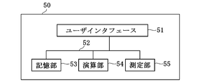
- the thermophysical property measuring apparatus 50 includes a user interface 51, a storage unit 53, a calculation unit 54, a measurement unit 55, and a bus 52 that connects them to each other.
- the user interface 51 has a function of receiving an operation command for the thermophysical property measuring apparatus 50 of the user and displaying the generated data so that the user can visually recognize the generated data.
- the storage unit 53 stores a program executed by the calculation unit 54 and stores data supplied via the bus 52.
- the calculation unit 54 performs a predetermined calculation on the supplied data by executing the above-described program stored in advance in the storage unit 53, and calculates a Thomson coefficient, absolute thermoelectric power, and thermal conductivity to be described later.
- the measuring unit 55 measures thermoelectric properties of a measurement object such as a thin metal wire (hereinafter referred to as “metal sample”).
- FIG. 2 is a diagram showing the configuration of the measurement unit 55 shown in FIG.
- the measurement unit 55 includes the chamber 1, metal blocks 2 and 3, thermocouples 5, 61 and 62, heaters 63 and 64, a temperature controller 65, and a voltage application unit 100.
- the voltage application unit 100 includes a positive DC power source 6, a negative DC power source 7, and a switch 9.
- the measurement points of the thermocouple 61 for measuring the temperature of the metal block 2 and the thermocouple 62 for measuring the temperature of the metal block 3 are the metal sample 4 and the metal block 2 respectively. , 3 are connected to the connected portion.
- the temperature controller 65 supplies a heater control signal corresponding to the temperature measured by the thermocouples 61 and 62 to the heaters 63 and 64, so that the temperatures of the metal blocks 2 and 3 are changed to temperatures T 1 and T, respectively.
- the heaters 63 and 64 for heating are controlled so as to supply a heat quantity of 2 .
- the metal sample 4 is installed in the measurement part 55 which has this structure as a measuring object, for example.
- the measurement unit 55 is designed so as to sufficiently satisfy the thermal boundary condition in the thermal analysis.
- the inside of the chamber 1 is evacuated to suppress heat convection transfer, and the temperatures T 1 and T are applied to both ends of the metal sample 4 to provide a temperature gradient to the metal sample 4 as described above.
- Two metal blocks 2 and 3 are connected. Although these metal blocks 2 and 3 have a function as a heat bath, accurate temperature control can be realized by using a Peltier element or the like while monitoring the temperature with thermocouples 61 and 62.
- thermocouple 5 is attached to the central portion (origin 0) of the metal sample 4 in order to measure heat absorption and heat generation due to the Thomson effect. At this time, in order to reduce the outflow of heat from the thermocouple 5, a thermocouple having a sufficiently small thermal conductance is attached, and the output voltage from the thermocouple 5 is measured by a DC voltmeter. In the high temperature region, it is conceivable to measure the temperature by using a radiation thermometer.
- a DC voltage generator 100 capable of generating DC voltages having different polarities is connected between both ends of the metal sample 4.
- the switch 9 selectively connects either the positive DC power supply 6 or the negative DC power supply 7 to both ends of the metal sample 4 in accordance with the control signal Ct.
- FIG. 3 is a flowchart showing a thermoelectric power measurement method according to the embodiment of the present invention. Below, the said thermoelectric power measuring method is demonstrated in detail using FIG.
- step S1 installing the temperatures T 1 and the temperature T 2 of the metal block 2, 3 on both ends of the metal sample 4.
- the metal blocks 2 and 3 are disposed at both ends of the metal sample 4, and the temperatures of the metal blocks 2 and 3 are set to temperatures T 1 and T 2 using the temperature controller 65 as described above.
- the temperature control of the metal blocks 2 and 3 by the temperature controller 65 may be performed at any timing as long as it is before entering Step S4 below.
- step S2 a thermocouple 5 is attached to the origin of the metal sample 4, and in step S3, the chamber 1 is evacuated.
- step S ⁇ b> 4 a positive DC voltage V + DC is applied to both ends of the metal sample 4, and the temperature T DC + at the origin of the metal sample 4 is measured with the thermocouple 5.
- step S 5 a negative DC voltage V ⁇ DC is applied to both ends of the metal sample 4, and the temperature T DC ⁇ at the origin of the metal sample 4 is measured with the thermocouple 5.
- applying the DC voltages V + DC and V ⁇ DC to both ends of the metal sample 4 in steps S4 and S5 applies a DC current to both ends of the sample.
- step S 6 the Thomson coefficient is calculated using the temperature T DC + and the temperature T DC ⁇ at the origin of the metal sample 4, and the absolute thermoelectric power of the metal sample 4 is calculated by the above equation (2) using the calculated Thomson coefficient. S is obtained.
- the calculation of the Thomson coefficient in this step will be described in detail.
- thermocouple 5 As shown in FIG. 2, a temperature difference is given to both ends of the metal sample 4, and at the same time, a direct current flows through the metal sample 4. At this time, the generated loss heat flow is a constant temperature (in this case, room temperature) heat bath (not shown) connected to the thermocouple 5 via the metal sample 4 and the thermocouple 5 attached to the origin. ).
- Equation (3) x is a position coordinate [m] with the midpoint of the metal sample 4 as the origin, T is a temperature [K] of the metal sample 4 at the position x, and ⁇ is a Thomson coefficient [ ⁇ V of the metal sample 4. / K], ⁇ is the electrical resistivity of the metal sample 4 [ ⁇ / m], p is the perimeter of the metal sample 4 [m], and ⁇ is a Stephan-Boltzmann constant [W / m 2 K 4 ]. , ⁇ represents the emissivity, T 0 represents the zero point temperature [K] of the thermocouple, and so on.
- the first term on the left side of the equation (3) means heat conduction in the metal sample 4
- the second term means heat generation and heat absorption by the Thomson effect
- the third term means Joule heat generation
- the fourth term means radiant heat
- Equation (4) The heat loss due to the radiation of the fourth term on the left side of Equation (4) is negligible because it is 1/100 or less of the Joule heat in the measurement temperature region.
- the temperature distribution of the metal sample 4 is determined by heat conduction through the solid, and the boundary condition does not take into account loss due to convective heat transfer, assuming measurement in a vacuum.
- the temperature distribution in the metal sample 4 is assumed to be sufficiently small, and physical properties such as Thomson coefficient, electrical conductivity, and thermal conductivity are also treated as constants. Under these assumptions, the equation (4) can be simplified as the following equation (5).
- C represents a coefficient related to the Thomson term
- D represents a coefficient related to the Joule term
- Equation (8) K 1 represents the thermal conductance of the thermocouple 5 and so on.
- the boundary condition shown by the equation (8) represents the heat loss from the thermocouple 5 attached to the origin of the metal sample 4.
- the temperature T DC [K] of the midpoint (origin) of the metal sample 4 when the DC voltage is applied can be obtained.
- N in the equation (9) is (1 + K 1 / K 0 ), which means the heat loss coefficient of the metal sample 4 through the thermocouple 5. (Same below).
- Equation (9) the first term represents the temperature rise due to Joule heat generation and the secondary Thomson effect, the second term corresponds to the initial temperature at the origin of the metal sample 4, and the third term represents the temperature due to the primary Thomson effect. Represents change.
- Equation (9) heat absorption and heat generation by the primary Thomson effect depend on the polarity of the DC voltage applied to the metal sample 4, whereas heat generation by the Joule effect and the secondary Thomson effect are of this polarity. Does not depend on.
- the positive DC power source 6 is connected to both ends of the metal sample 4, and the temperature distribution when a DC current is passed through the metal sample 4 in the positive direction is T DC + , and the negative DC current is applied to both ends of the metal sample 4.
- T DC- the temperature distribution when a direct current is passed through the metal sample 4 in the negative direction with the power supply 7 connected
- an average temperature difference ⁇ T DC ⁇ and an average value ⁇ T DC + at the origin of the metal sample 4 are defined as in the following equations (12) and (13).
- the average difference ⁇ T DC ⁇ is expressed by the following expression (14).
- the average difference ⁇ T DC ⁇ can be expressed by the first-order Thomson effect term because the Joule heat generation term and the second-order Thomson effect term cancel each other.
- Equation (10) and Equation (11) the average value ⁇ T DC + cancels the first-order Thomson effect, and can be expressed by the terms of Joule heating and the second-order Thomson effect.
- the product of C and l (lower-case el) is a small value, and C 2 l 2 which is the term of the second-order Thomson effect can be ignored. Therefore, the average value ⁇ T DC + Can be approximated.
- Equation (14) can be transformed into the following equation (16) using physical quantities such as a Joule heat generation term, a Thomson coefficient, an electric resistance, a current, and a temperature difference between both ends of the metal sample 4.
- R represents the electrical resistance [ ⁇ ] of the metal sample 4, and so on.
- Equation (17) does not include the thermal conductivity, dimensions, and heat loss coefficient of the metal sample 4 as variables, and includes the average difference ⁇ T DC ⁇ and the average value ⁇ T DC + .
- the calculation of the Thomson coefficient and the absolute thermoelectric power using Expression (17) will be described in detail with reference to FIG.
- FIG. 4 is a graph showing a temperature distribution of the metal sample 4 when a DC voltage is applied to both ends of the metal sample 4.
- the horizontal axis represents position coordinates with the midpoint of the metal sample 4 as the origin, and the vertical axis represents the temperature of the metal sample 4.
- the metal sample 4 In the initial state, the temperature gradient between the temperatures T 1 and T 2 is proportional to the distance from one end. From this, the initial temperature T S at the origin of the metal sample 4 is (T 1 + T 2 ) / 2.
- the temperature distribution of the metal sample 4 when the positive DC voltage V + DC is applied to both ends of the metal sample 4 in step S4 is shown by the graph 30, and in step S5, the negative electrode is applied to both ends of the metal sample 4.
- the graph 20 shows the temperature distribution of the metal sample 4 when the direct current voltage V 1 -DC is applied.
- the temperature distribution of the metal sample 4 when there is no Joule heat effect due to the current is offset by flowing the current with the polarity reversed as described above. Is shown by the graph 10 located at.
- the temperature at the origin when the effect due to the current is discarded can be evaluated as (T DC + + T DC ⁇ ) / 2, that is, the average value ⁇ T DC + described above.
- step S6 the calculation unit 54 executes the program stored in advance in the storage unit 53, and uses the obtained temperature T DC + and temperature T DC ⁇ to calculate the Thomson coefficient ⁇ according to the above equation (17).
- the absolute thermoelectric power S of the metal sample 4 is calculated by the above equation (2) using the calculated Thomson coefficient ⁇ .
- the calculation unit 54 can also calculate the thermal conductivity ⁇ by the following equation (18) using the calculated Thomson coefficient ⁇ .
- thermopower and thermal conductivity values calculated as described above are stored in the storage unit 53, and the user interface 51 is in accordance with a predetermined operation command input by the user of the thermophysical property measuring apparatus 50. The value is displayed so that the user can recognize it visually.
- thermophysical property measuring method and thermophysical property measuring apparatus As described above, according to the thermophysical property measuring method and thermophysical property measuring apparatus according to the embodiment of the present invention, the magnitude and electric resistance of the direct current flowing through the metal sample 4 are measured and applied to both ends of the metal sample 4. Since the Thomson coefficient can be calculated by measuring the temperature of the metal sample 4 by controlling the polarity of the DC voltage or DC current, absolute thermopower and thermal conductivity values can be easily obtained.
- thermophysical property measuring method and thermophysical property measuring apparatus when calculating the Thomson coefficient, the thermal conductivity of the metal sample 4 that is generally difficult to measure with high accuracy.
- Thomson coefficient with high accuracy because there is no need to measure the size, heat loss coefficient, and heat loss due to electromagnetic radiation to the measurement space according to the AC frequency generated by using an AC power supply Absolute thermopower and thermal conductivity can be obtained.
Landscapes
- Physics & Mathematics (AREA)
- General Physics & Mathematics (AREA)
- General Health & Medical Sciences (AREA)
- Chemical & Material Sciences (AREA)
- Analytical Chemistry (AREA)
- Biochemistry (AREA)
- Life Sciences & Earth Sciences (AREA)
- Health & Medical Sciences (AREA)
- Immunology (AREA)
- Pathology (AREA)
- Engineering & Computer Science (AREA)
- Power Engineering (AREA)
- Investigating Or Analyzing Materials Using Thermal Means (AREA)
Abstract
本発明は、簡便に精度の高い絶対熱電能や熱伝導率を得ることのできる熱物性測定方法及び熱物性測定装置を提供することを目的とする。 本目的を実現するため、本発明は、温度勾配を与えた金属の両端に直流電圧または直流電流を印加して、上記金属の中央部における第一の温度を測定する第一のステップと、上記金属の両端に極性の異なる直流電圧または直流電流を印加して、上記金属の中央部における第二の温度を測定する第二のステップと、第一及び第二のステップで測定された第一及び第二の温度を用いて上記金属のトムソン係数を算出する第三のステップと、第三のステップにおいて算出されたトムソン係数を用いて上記金属の絶対熱電能または熱伝導率の少なくとも一方を算出する第四のステップとを有し、第三のステップは、第一の温度と第二の温度の差の平均値を算出するステップと、第一の温度と第二の温度の和の平均値を算出するステップと、上記金属を流れる電流の大きさ、上記金属の電気抵抗、及び上記差の平均値との積を、第一の温度と第二の温度の差、及び上記和の平均値で除するステップとを含む熱物性測定方法を提供する。
Description
本発明は、熱物性値を測定するための方法及び装置に関するものである。
未利用熱発電として期待される熱電変換発電デバイスの変換効率の指標となることから、信頼性の高い熱電能測定技術の確立は重要な課題である。一般に熱電能は白金に対する相対値として計測されるものであり、熱電発電モジュールの効率推定や最適な熱設計に必要なパラメータの中で唯一、材料単体の物性測定が困難な物理量であった。このため、トムソン熱の測定により、基準となる白金、鉛、銅などの材料単体の絶対熱電能を精密に決定する試みがなされている。
ここで、既存のトムソン係数算出法では、試料の熱伝導率、寸法、及び熱電対からの熱損失係数について正確な値が必要となるが、これらの物理量を正確に測定するのは困難であるため、本願に係る出願人は特許文献1において、交流電源を利用した絶対熱電能の測定法を提案した。
しかし、特許文献1に開示された測定法を実施するためには、交流電源のほか、直流電源とこれら両電源を選択的に測定対象へ接続するためのスイッチを備えた測定装置を制御する必要があり、測定装置及び測定法が複雑化するという問題がある。また、本測定法は交流電源を利用することに伴い、測定空間への交流周波数に応じた電磁放射、測定試料のインダクタンスや浮遊静電容量による熱損失を考慮する必要が生じるという問題がある。さらに、トムソン効果による発熱や吸熱が充分小さくなる遮断(カットオフ)周波数は試料の幾何形状や物性に依存するため、測定対象の材質や形状が制限されるという問題もある。
本発明は、このような問題を解決するためになされたもので、簡便に精度の高い絶対熱電能や熱伝導率を得ることのできる熱物性測定方法及び熱物性測定装置を提供することを目的とする。
上記課題を解決するため、本発明は、温度勾配を与えた金属の両端に直流電圧または直流電流を印加して、上記金属の中央部における第一の温度を測定する第一のステップと、上記金属の両端に極性の異なる直流電圧または直流電流を印加して、上記金属の中央部における第二の温度を測定する第二のステップと、第一及び第二のステップで測定された第一及び第二の温度を用いて上記金属のトムソン係数を算出する第三のステップと、第三のステップにおいて算出されたトムソン係数を用いて上記金属の絶対熱電能または熱伝導率の少なくとも一方を算出する第四のステップとを有し、第三のステップは、第一の温度と第二の温度の差の平均値を算出するステップと、第一の温度と第二の温度の和の平均値を算出するステップと、上記金属を流れる電流の大きさ、上記金属の電気抵抗、及び上記差の平均値との積を、第一の温度と第二の温度の差、及び上記和の平均値で除するステップとを含む熱物性測定方法を提供する。
また、上記課題を解決するため、本発明は、温度勾配を与えた金属の両端に直流電圧を印加する電圧印加部と、電圧印加部により直流電圧を印加したときにおける上記金属の中央部の第一の温度と、電圧印加部により極性の異なる直流電圧を印加したときにおける上記金属の中央部の第二の温度とを測定する温度測定部と、温度測定部により測定された第一及び第二の温度の差の平均値と、第一及び第二の温度の和の平均値を算出した上で、上記金属を流れる電流の大きさ、上記金属の電気抵抗、及び上記差の平均値との積を、第一の温度と第二の温度の差、及び上記和の平均値で除することによって上記金属のトムソン係数を算出し、上記トムソン係数を用いて上記金属の絶対熱電能または熱伝導率の少なくとも一方を算出する熱物性算出部とを備えた熱物性測定装置を提供する。
本発明によれば、簡便に精度の高い絶対熱電能や熱伝導率を得ることができる。
以下において、本発明の実施の形態を図面を参照しつつ詳しく説明する。なお、図中同一符号は同一又は相当部分を示す。
鉛、銅、白金等の金属材料の熱電能の絶対値は、物性測定の分野において広く用いられている熱電能の相対測定法に欠かせない物性値である。絶対熱電能は、金属材料の熱電能がゼロとなる状態を利用し、超伝導体を基準物質とした比較測定によって導かれている。この方法は、測定可能な温度領域が超伝導転移温度より低い温度に制限されてしまうことから、測定温度領域を拡大するためには、測定可能なトムソン係数からケルビンの関係式を用いて絶対熱電能を導くことが必要となる。
ここで、一般的に熱電能Sは、金属や半導体に温度差ΔTを与えた時に発生する電圧ΔVを用いて、S=ΔV/ΔTと定義される。この定義に基づく熱電能の測定値は、正確には測定対象金属と配線材料(金属)との相対値、すなわち熱電能の差に該当するため、測定対象金属の絶対熱電能を求めるためには、配線材料の熱電能を考慮した補正が必要となる。特に、測定対象金属の熱電能が数十μV/K程度の場合には、このような補正の影響を無視することはできない。
一方、上記のトムソン係数μは以下の式(1)で表されることが知られている。

なお、上式において、T1とT2は測定対象とされる金属の両端に電圧が印加されるときにおける当該両端の温度[K]、Iは上記金属に流れる電流[A]、分母の小文字エル(以下「l」とも表す。)は上記金属の端から中点までの長さ[m]、κは上記金属の熱伝導率[W/mK]、aは上記金属の断面積[m2]、δTは後述するように、極性を反転させた直流電圧を測定対象に印加したときに生じる上記金属の中点における温度変化の1/2[K]をそれぞれ示し、以下同様である。
そして、絶対熱電能Sはケルビンの式、すなわち以下の式(2)により算出される。

なお、上式においてT0は、超伝導転移温度を意味する。
ここで、式(2)より、精度の高い絶対熱電能Sを求めるためには、正確なトムソン係数μが必要となることが分かる。
ここで、式(2)より、精度の高い絶対熱電能Sを求めるためには、正確なトムソン係数μが必要となることが分かる。
そこで、以下においては、測定によって精度の高いトムソン係数μを得るための熱物性測定装置及び熱物性測定方法について詳しく説明する。
図1は、本発明の実施の形態に係る熱物性測定装置50の構成を示すブロック図である。図1に示されるように、熱物性測定装置50は、ユーザインタフェース51と、記憶部53と、演算部54と、測定部55と、これらを互いに接続するバス52とを含む。
ここで、ユーザインタフェース51は、ユーザの熱物性測定装置50に対する動作命令を受け付けると共に、生成されたデータをユーザが目視により認識できるよう表示する機能を有する。また、記憶部53は、演算部54が実行するプログラムを格納すると共に、バス52を介して供給されたデータを記憶する。また、演算部54は、記憶部53に予め格納された上記プログラムを実行することにより、供給されたデータについて所定の演算を行い、後述するトムソン係数と、絶対熱電能や熱伝導率を算出する。そして、測定部55は、金属細線(以下、「金属試料」という。)等の測定対象が持つ熱電特性を測定する。
図2は、図1に示された測定部55の構成を示す図である。図2に示されるように、測定部55はチャンバ1と、金属ブロック2,3と、熱電対5,61,62と、加熱用ヒータ63,64と、温度コントローラ65と、電圧印加部100とを含み、電圧印加部100は正極性直流電源6と、負極性直流電源7と、スイッチ9とを含む。
また、図2に示されるように、金属ブロック2の温度を測定するための熱電対61と金属ブロック3の温度を測定するための熱電対62の測定点はそれぞれ、金属試料4と金属ブロック2,3とが接続される部分に配置される。そして、温度コントローラ65は、熱電対61,62で測定された温度に応じたヒータ制御信号を加熱用ヒータ63,64へ供給することによって、金属ブロック2,3の温度がそれぞれ温度T1,T2となるような熱量を供給するよう加熱用ヒータ63,64を制御する。
そして、かかる構成を有する測定部55に、測定対象として例えば金属試料4が設置される。
ここで、測定部55は、熱解析における熱的境界条件を十分に満足できるように設計されている。具体的には、チャンバ1内は熱の対流伝達を抑制するために真空とされ、金属試料4の両端には上記のように、当該金属試料4に温度勾配を与えるために温度T1,T2の金属ブロック2,3が接続される。これらの金属ブロック2,3は熱浴としての機能を有するが、熱電対61,62で温度をモニタリングしつつペルチェ素子等を用いることにより、精度のよい温度制御を実現することができる。
ここで、測定部55は、熱解析における熱的境界条件を十分に満足できるように設計されている。具体的には、チャンバ1内は熱の対流伝達を抑制するために真空とされ、金属試料4の両端には上記のように、当該金属試料4に温度勾配を与えるために温度T1,T2の金属ブロック2,3が接続される。これらの金属ブロック2,3は熱浴としての機能を有するが、熱電対61,62で温度をモニタリングしつつペルチェ素子等を用いることにより、精度のよい温度制御を実現することができる。
なお、金属試料4に温度勾配を与える方法としては、雰囲気制御を可能とする管状炉を用いる他、安定なヒータを利用すること等も考えられる。
また、金属試料4の中央部(原点0)には、トムソン効果による吸熱及び発熱を測定するために熱電対5が取り付けられる。このとき、熱電対5からの熱の流出を低減するため、熱コンダクタンスの十分小さな熱電対が取り付けられ、熱電対5からの出力電圧は直流電圧計によって測定される。なお、高温領域では、放射温度計を用いることにより温度を測定することも考えられる。
また、金属試料4の両端間には、極性の異なる直流電圧を発生することが可能な直流電圧発生器100が接続される。
また、スイッチ9は、制御信号Ctに応じて、正極性直流電源6と負極性直流電源7のいずれか一方を、選択的に金属試料4の両端に接続する。
図3は、本発明の実施の形態に係る熱電能測定方法を示すフローチャートである。以下において、当該熱電能測定方法を図3を用いて詳しく説明する。
まずステップS1において、金属試料4の両端に温度T1と温度T2の金属ブロック2,3を設置する。具体的には、金属試料4の両端に金属ブロック2,3を配設し、上記のように、温度コントローラ65を用いて金属ブロック2,3の温度をそれぞれ温度T1,T2とする。なお、温度コントローラ65による金属ブロック2,3の当該温度制御は、以下のステップS4に入る前であれば、いずれのタイミングで行っても良い。
次に、ステップS2において、金属試料4の原点に熱電対5を取り付け、ステップS3において、チャンバ1内を真空にする。次に、ステップS4において、金属試料4の両端に正極性の直流電圧V+DCを印加して、金属試料4の原点における温度TDC+を熱電対5で測定する。次に、ステップS5において、金属試料4の両端に負極性の直流電圧V-DCを印加して、金属試料4の原点における温度TDCーを熱電対5で測定する。
なお、ステップS4及びステップS5において金属試料4の両端に直流電圧V+DC, V-DCを印加することは、同試料の両端に直流電流を印加することになることは言うまでもない。
なお、ステップS4及びステップS5において金属試料4の両端に直流電圧V+DC, V-DCを印加することは、同試料の両端に直流電流を印加することになることは言うまでもない。
そして、ステップS6において、金属試料4の原点における温度TDC+と温度TDCーを用いてトムソン係数を算出し、算出されたトムソン係数を用いて上式(2)により金属試料4の絶対熱電能Sを求める。以下において、本ステップにおけるトムソン係数の算出について詳述する。
図2に示されるように、金属試料4の両端には温度差が与えられ、同時に、金属試料4には直流電流が流される。このとき、発生する損失熱流は、金属試料4とその原点に取り付けられた熱電対5を介して、熱電対5に接続された温度一定(この場合は室温)の熱浴(図示していない。)に流れることになる。
ここで、熱的な境界条件を満たす金属試料4に直流電流Iを流した場合、金属試料4の定常状態における熱伝導方程式は、次式(3)のように表現される。

なお、式(3)において、xは金属試料4における中点を原点とした位置座標[m]、Tは位置xにおける金属試料4の温度[K]、μは金属試料4のトムソン係数[μV/K]、ρは金属試料4の電気抵抗率[Ω/m]、pは金属試料4の周囲長[m]、σはステファン・ボルツマン(Stephan-Boltzmann)定数[W/m2K4]、εは輻射率、T0は熱電対のゼロ点温度[K]をそれぞれ示し、以下同様である。
そして、式(3)の左辺第一項は金属試料4における熱伝導、同第二項はトムソン効果による発熱と吸熱、同第三項はジュール発熱、同第四項は輻射熱をそれぞれ意味し、定常状態の解析を行っていることから右辺はゼロとなる。
式(3)の両辺をaκで割ると、次式(4)となる。

式(4)の左辺第四項の輻射に起因する熱損失は、測定温度領域においてはジュール熱の1/100以下であることから無視できる。ここで、金属試料4の温度分布は固体を介した熱伝導により決定されるものとし、境界条件では真空中での測定を想定した上で、対流熱伝達による損失も考慮に入れない。さらに、金属試料4内の温度分布は十分小さいものとし、トムソン係数、電気伝導率、熱伝導率などの物性値も定数として扱う。これらの仮定の下では、式(4)を次式(5)のように簡素化することができる。

ここで、トムソン効果に起因する定数Cと、ジュール発熱に起因する定数Dは、次式(6)のように定義される。

図2を参照すると、境界条件は以下の式(7)及び式(8)で与えられる。


なお、式(8)において、K1は熱電対5の熱コンダクタンスを示し、以下同様である。
式(8)で示される境界条件は、金属試料4の原点に取り付けられた熱電対5からの熱損失を表している。ここで、位置xについて二次以上の項を無視して級数展開すると、直流電圧印加時における金属試料4の中点(原点)の温度TDC[K]を得ることができる。

式(9)において、第一項はジュール発熱及び二次のトムソン効果による温度上昇を表し、第二項は金属試料4の原点における初期温度に相当し、第三項は一次のトムソン効果による温度変化を表す。
式(9)に示されるように、一次のトムソン効果による吸熱及び発熱は、金属試料4に印加する直流電圧の極性に依存するのに対し、ジュール効果及び二次のトムソン効果による発熱は本極性に依存しない。そこで、金属試料4の両端に正極性直流電源6を接続して金属試料4に位置座標が正の方向へ直流電流を流した際の温度分布をTDC+、金属試料4の両端に負極性直流電源7を接続して金属試料4に位置座標が負の方向へ直流電流を流した際の温度分布をTDCーとすると(以下同様)、式(9)から以下の式(10)及び式(11)を得ることができる。


ここで、金属試料4の原点における温度の平均差δTDC-及び平均値δTDC+を、次の式(12)及び式(13)のように定義する。

式(12)に式(10)及び式(11)を代入すると、平均差δTDC-は以下の式(14)で示される。ここで平均差δTDC-は、ジュール発熱の項と二次のトムソン効果の項が相殺されるため、一次のトムソン効果の項で表すことができることになる。

一方、式(13)に式(10)及び式(11)を代入すると、平均値δTDC+は一次のトムソン効果が相殺され、ジュール発熱の項と二次のトムソン効果の項で表すことができる。ここで、金属ではCとl(小文字エル)の積が小さな値となり、二次のトムソン効果の項であるC2l2を無視できるため、平均値δTDC+は次式(15)のように近似できる。

また、式(14)は、ジュール発熱項、トムソン係数、電気抵抗、電流、及び金属試料4の両端の温度差という物理量を用いて、次式(16)のように変形できる。

なお、式(16)において、Rは金属試料4の電気抵抗[Ω]を示し、以下同様である。
そして、式(16)に式(15)を代入してトムソン係数μについて解くと、次式(17)が得られる。

式(17)は、変数として金属試料4の熱伝導率や寸法、熱損失係数を含まず、上記平均差δTDC-及び平均値δTDC+を含む。以下において、式(17)を利用したトムソン係数及び絶対熱電能の算出について、図4を参照しつつ詳しく説明する。
図4は、金属試料4の両端に直流電圧を印加したときにおける金属試料4の温度分布を示すグラフである。ここで、横軸は金属試料4の中点を原点とした位置座標、縦軸は金属試料4の温度を示す。上記のように、全長2l(小文字エル)の金属試料4の両端には温度T1と温度T2の金属ブロック2,3が設置されるため、グラフ40に示されるように、金属試料4は初期状態において温度T1,T2間で一端からの距離に定比例した温度勾配を有する。このことから、金属試料4の原点における初期温度TSは(T1+T2)/2となる。
そして、上記のようにステップS4において金属試料4の両端に正極性の直流電圧V+DCを印加したときの金属試料4の温度分布はグラフ30で示され、ステップS5において金属試料4の両端に負極性の直流電圧V-DCを印加したときの金属試料4の温度分布はグラフ20で示される。
このとき、電流によるジュール熱の効果がないときの金属試料4の温度分布は、上記のように極性の反転した電流を流すことにより該効果が相殺されることから、グラフ20とグラフ30の中間に位置するグラフ10で示される。
これより、金属試料4に直流電圧を印加した場合において、電流による効果を捨象したときの原点における温度は(TDC++TDCー)/2、すなわち上記の平均値δTDC+と評価することができる。なお、図1に示された演算部54は、温度TDC+と温度TDCーとの差の1/2を計算することにより、上記の平均差δTDC-を算出する。
そして、ステップS6において、演算部54は、記憶部53に予め格納されたプログラムを実行することにより、得られた温度TDC+及び温度TDCーを用いて上式(17)によりトムソン係数μを算出し、算出されたトムソン係数μを用いて上式(2)により金属試料4の絶対熱電能Sを算出する。ここで演算部54は、算出されたトムソン係数μを用いて、以下の式(18)により熱伝導率κを算出することもできる。

なお、上記のように算出された絶対熱電能や熱伝導率の値は記憶部53に記憶され、ユーザインタフェース51は、熱物性測定装置50のユーザにより入力された所定の動作命令に応じて、当該値をユーザが目視により認識できるよう表示する。
以上より、本発明の実施の形態に係る熱物性測定方法及び熱物性測定装置によれば、金属試料4に流れる直流電流の大きさ及び電気抵抗を測定すると共に、金属試料4の両端に印加する直流電圧や直流電流の極性を制御して金属試料4の温度を測定することによりトムソン係数を算出することができるため、簡便に絶対熱電能や熱伝導率の値を得ることができる。
また、本発明の実施の形態に係る熱物性測定方法及び熱物性測定装置によれば、トムソン係数を算出する際において、一般的に精度の高い測定が困難とされる金属試料4の熱伝導率や寸法、熱損失係数を測定する必要がなく、かつ、交流電源を使用することによって生じる交流周波数に応じた測定空間への電磁放射による熱損失を考慮する必要もないため、精度の高いトムソン係数と、絶対熱電能や熱伝導率を得ることができる。
2,3 金属ブロック
4 金属細線(金属試料)
5,61,62 熱電対
6 正極性直流電源
7 負極性直流電源
9 スイッチ
50 熱物性測定装置
54 演算部
55 測定部
63,64 加熱用ヒータ
65 温度コントローラ
100 直流電圧発生器。
4 金属細線(金属試料)
5,61,62 熱電対
6 正極性直流電源
7 負極性直流電源
9 スイッチ
50 熱物性測定装置
54 演算部
55 測定部
63,64 加熱用ヒータ
65 温度コントローラ
100 直流電圧発生器。
Claims (5)
- 温度勾配を与えた金属の両端に直流電圧または直流電流を印加して、前記金属の中央部における第一の温度を測定する第一のステップと、
前記金属の両端に極性の異なる直流電圧または直流電流を印加して、前記金属の中央部における第二の温度を測定する第二のステップと、
前記第一及び第二のステップで測定された前記第一及び第二の温度を用いて前記金属のトムソン係数を算出する第三のステップと、
前記第三のステップにおいて算出された前記トムソン係数を用いて前記金属の絶対熱電能または熱伝導率の少なくとも一方を算出する第四のステップとを有し、
前記第三のステップは、
前記第一の温度と前記第二の温度の差の平均値を算出するステップと、
前記第一の温度と前記第二の温度の和の平均値を算出するステップと、
前記金属を流れる電流の大きさ、前記金属の電気抵抗、及び前記差の平均値との積を、前記第一の温度と前記第二の温度の差、及び前記和の平均値で除するステップとを含む熱物性測定方法。 - 温度勾配を与えた金属の両端に直流電圧を印加する電圧印加手段と、
前記電圧印加手段により前記直流電圧を印加したときにおける前記金属の中央部の第一の温度と、前記電圧印加手段により極性の異なる前記直流電圧を印加したときにおける前記金属の中央部の第二の温度とを測定する温度測定手段と、
前記温度測定手段により測定された前記第一及び第二の温度の差の平均値と、前記第一及び第二の温度の和の平均値を算出した上で、前記金属を流れる電流の大きさ、前記金属の電気抵抗、及び前記差の平均値との積を、前記第一の温度と前記第二の温度の差、及び前記和の平均値で除することによって前記金属のトムソン係数を算出し、前記トムソン係数を用いて前記金属の絶対熱電能または熱伝導率の少なくとも一方を算出する熱物性算出手段とを備えた熱物性測定装置。 - 前記電圧印加手段は、
前記金属に正極性の前記直流電圧を印加する第一の直流電源と、
前記金属に負極性の前記直流電圧を印加する第二の直流電源と、
前記金属の両端へ、前記第一若しくは前記第二の直流電源の一方を選択的に接続するスイッチング手段とを含む請求項2に記載の熱物性測定装置。 - 前記金属の両端に接続された二つの金属ブロックと、
前記二つの金属ブロックを異なる温度に設定する温度設定手段とをさらに備えた請求項2に記載の熱物性測定装置。 - 前記金属ブロックの温度を前記金属との接続部分で測定する熱電対をさらに備え、
前記温度設定手段は、前記熱電対で測定された温度に応じて前記金属ブロックの温度を設定する請求項4に記載の熱物性測定装置。
Priority Applications (2)
| Application Number | Priority Date | Filing Date | Title |
|---|---|---|---|
| JP2018508821A JP6607469B2 (ja) | 2016-03-29 | 2017-02-28 | 熱物性測定方法及び熱物性測定装置 |
| US16/086,691 US10876983B2 (en) | 2016-03-29 | 2017-02-28 | Thermophysical property measurement method and thermophysical property measurement apparatus |
Applications Claiming Priority (2)
| Application Number | Priority Date | Filing Date | Title |
|---|---|---|---|
| JP2016065284 | 2016-03-29 | ||
| JP2016-065284 | 2016-03-29 |
Publications (1)
| Publication Number | Publication Date |
|---|---|
| WO2017169462A1 true WO2017169462A1 (ja) | 2017-10-05 |
Family
ID=59962963
Family Applications (1)
| Application Number | Title | Priority Date | Filing Date |
|---|---|---|---|
| PCT/JP2017/007792 Ceased WO2017169462A1 (ja) | 2016-03-29 | 2017-02-28 | 熱物性測定方法及び熱物性測定装置 |
Country Status (3)
| Country | Link |
|---|---|
| US (1) | US10876983B2 (ja) |
| JP (1) | JP6607469B2 (ja) |
| WO (1) | WO2017169462A1 (ja) |
Cited By (2)
| Publication number | Priority date | Publication date | Assignee | Title |
|---|---|---|---|---|
| JP2019120531A (ja) * | 2017-12-28 | 2019-07-22 | 国立研究開発法人産業技術総合研究所 | 熱物性測定装置及び熱物性測定方法 |
| CN110108930A (zh) * | 2019-05-23 | 2019-08-09 | 深港产学研基地(北京大学香港科技大学深圳研修院) | 基于悬浮低维热电材料的微纳微波功率传感器及测量方法 |
Families Citing this family (1)
| Publication number | Priority date | Publication date | Assignee | Title |
|---|---|---|---|---|
| CN116108640B (zh) * | 2022-12-28 | 2023-09-19 | 南京苏夏设计集团股份有限公司 | 一种蒸汽管网温降计算方法、存储介质及设备 |
Citations (1)
| Publication number | Priority date | Publication date | Assignee | Title |
|---|---|---|---|---|
| WO2015025586A1 (ja) * | 2013-08-22 | 2015-02-26 | 独立行政法人産業技術総合研究所 | 熱物性測定方法及び熱物性測定装置 |
-
2017
- 2017-02-28 WO PCT/JP2017/007792 patent/WO2017169462A1/ja not_active Ceased
- 2017-02-28 US US16/086,691 patent/US10876983B2/en not_active Expired - Fee Related
- 2017-02-28 JP JP2018508821A patent/JP6607469B2/ja active Active
Patent Citations (1)
| Publication number | Priority date | Publication date | Assignee | Title |
|---|---|---|---|---|
| WO2015025586A1 (ja) * | 2013-08-22 | 2015-02-26 | 独立行政法人産業技術総合研究所 | 熱物性測定方法及び熱物性測定装置 |
Non-Patent Citations (2)
| Title |
|---|
| AMAGAI, YASUTAKA ET AL.: "AC/DC Transfer Technique for Measuring Thomson Coefficient: Toward Thermoelectric Metrology", IEEE TRANSACTIONS ON INSTRUMENTATION AND MEASUREMENT, vol. 64, no. 6, 1 June 2015 (2015-06-01), pages 1576 - 1581, XP011580565 * |
| ROBERTS, R. B. ET AL.: "The absolute scale of thermoelectricity", PHILOSOPHICAL MAGAZINE, vol. 36, no. 1, 1977, pages 91 - 107 * |
Cited By (3)
| Publication number | Priority date | Publication date | Assignee | Title |
|---|---|---|---|---|
| JP2019120531A (ja) * | 2017-12-28 | 2019-07-22 | 国立研究開発法人産業技術総合研究所 | 熱物性測定装置及び熱物性測定方法 |
| JP7079471B2 (ja) | 2017-12-28 | 2022-06-02 | 国立研究開発法人産業技術総合研究所 | 熱物性測定装置及び熱物性測定方法 |
| CN110108930A (zh) * | 2019-05-23 | 2019-08-09 | 深港产学研基地(北京大学香港科技大学深圳研修院) | 基于悬浮低维热电材料的微纳微波功率传感器及测量方法 |
Also Published As
| Publication number | Publication date |
|---|---|
| US20190086346A1 (en) | 2019-03-21 |
| US10876983B2 (en) | 2020-12-29 |
| JPWO2017169462A1 (ja) | 2018-11-29 |
| JP6607469B2 (ja) | 2019-11-20 |
Similar Documents
| Publication | Publication Date | Title |
|---|---|---|
| JP6202580B2 (ja) | 熱物性測定方法及び熱物性測定装置 | |
| JP6607469B2 (ja) | 熱物性測定方法及び熱物性測定装置 | |
| Anatychuk et al. | On improvement of the accuracy and speed in the process of measuring characteristics of thermoelectric materials | |
| Pavlasek et al. | Hysteresis effects and strain-induced homogeneity effects in base metal thermocouples | |
| Han et al. | A built-in temperature sensor in an integrated microheater | |
| KR20170090351A (ko) | 곡면형 열전 소자의 특성 측정용 고온 구조체, 이를 이용한 특성 측정 시스템 및 방법 | |
| JP7079471B2 (ja) | 熱物性測定装置及び熱物性測定方法 | |
| CN109613054B (zh) | 一种直接通电纵向导热系数测试方法 | |
| JP4284545B2 (ja) | 比熱容量測定方法及び装置 | |
| JP7250268B2 (ja) | 比熱とエンタルピー変化の測定方法 | |
| JP4528954B1 (ja) | 導電性試料の比熱容量及び半球全放射率の測定方法及び装置 | |
| KR101662713B1 (ko) | 열전박막의 수직방향 열전특성 측정센서유닛 | |
| KR101230492B1 (ko) | 열전소자 평가 장치의 온도 제어 시스템 및 방법 | |
| JP7016141B2 (ja) | 熱物性測定装置及び熱物性測定方法 | |
| CN105785102B (zh) | 微尺度样品的热电势测量电路、平台及方法 | |
| Pierce et al. | Measuring thermal substrate resistance and impact on the characterization of thermoelectric modules | |
| JP5414068B2 (ja) | 導電性試料の比熱容量及び半球全放射率の測定方法及び装置 | |
| Anatychuk et al. | Increasing the rapidity of thermal conductivity measurement by the absolute method | |
| Anatychuk et al. | Automated equipment for measurement of properties of thermoelectric material rods | |
| JP2016031330A (ja) | 熱伝導率測定システム | |
| JP2019132760A (ja) | 熱特性測定方法及びその装置 | |
| Bode | Measurements of the thermal conductivity of metals at high temperatures | |
| Ogura et al. | Comparison of Co–C Eutectic-Point Cells for Thermocouple Calibration Between SP and NMIJ | |
| Anatychuk et al. | Semiconductor Thermoelectric Converters with Improved Precision | |
| Kochan et al. | Thermocouple with adjustable error |
Legal Events
| Date | Code | Title | Description |
|---|---|---|---|
| ENP | Entry into the national phase |
Ref document number: 2018508821 Country of ref document: JP Kind code of ref document: A |
|
| NENP | Non-entry into the national phase |
Ref country code: DE |
|
| 121 | Ep: the epo has been informed by wipo that ep was designated in this application |
Ref document number: 17774007 Country of ref document: EP Kind code of ref document: A1 |
|
| 122 | Ep: pct application non-entry in european phase |
Ref document number: 17774007 Country of ref document: EP Kind code of ref document: A1 |