WO2017169307A1 - 部材の接合方法 - Google Patents
部材の接合方法 Download PDFInfo
- Publication number
- WO2017169307A1 WO2017169307A1 PCT/JP2017/006410 JP2017006410W WO2017169307A1 WO 2017169307 A1 WO2017169307 A1 WO 2017169307A1 JP 2017006410 W JP2017006410 W JP 2017006410W WO 2017169307 A1 WO2017169307 A1 WO 2017169307A1
- Authority
- WO
- WIPO (PCT)
- Prior art keywords
- joining
- aluminum pipe
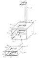
- caulking
- support component
- insertion hole
- Prior art date
- Legal status (The legal status is an assumption and is not a legal conclusion. Google has not performed a legal analysis and makes no representation as to the accuracy of the status listed.)
- Ceased
Links
Images











Classifications
-
- B—PERFORMING OPERATIONS; TRANSPORTING
- B21—MECHANICAL METAL-WORKING WITHOUT ESSENTIALLY REMOVING MATERIAL; PUNCHING METAL
- B21D—WORKING OR PROCESSING OF SHEET METAL OR METAL TUBES, RODS OR PROFILES WITHOUT ESSENTIALLY REMOVING MATERIAL; PUNCHING METAL
- B21D39/00—Application of procedures in order to connect objects or parts, e.g. coating with sheet metal otherwise than by plating; Tube expanders
- B21D39/08—Tube expanders
- B21D39/20—Tube expanders with mandrels, e.g. expandable
- B21D39/203—Tube expanders with mandrels, e.g. expandable expandable by fluid or elastic material
- B21D39/206—Tube expanders with mandrels, e.g. expandable expandable by fluid or elastic material by axially compressing the elastic material
-
- B—PERFORMING OPERATIONS; TRANSPORTING
- B21—MECHANICAL METAL-WORKING WITHOUT ESSENTIALLY REMOVING MATERIAL; PUNCHING METAL
- B21D—WORKING OR PROCESSING OF SHEET METAL OR METAL TUBES, RODS OR PROFILES WITHOUT ESSENTIALLY REMOVING MATERIAL; PUNCHING METAL
- B21D39/00—Application of procedures in order to connect objects or parts, e.g. coating with sheet metal otherwise than by plating; Tube expanders
- B21D39/06—Application of procedures in order to connect objects or parts, e.g. coating with sheet metal otherwise than by plating; Tube expanders of tubes in openings, e.g. rolling-in
-
- B—PERFORMING OPERATIONS; TRANSPORTING
- B21—MECHANICAL METAL-WORKING WITHOUT ESSENTIALLY REMOVING MATERIAL; PUNCHING METAL
- B21D—WORKING OR PROCESSING OF SHEET METAL OR METAL TUBES, RODS OR PROFILES WITHOUT ESSENTIALLY REMOVING MATERIAL; PUNCHING METAL
- B21D39/00—Application of procedures in order to connect objects or parts, e.g. coating with sheet metal otherwise than by plating; Tube expanders
- B21D39/04—Application of procedures in order to connect objects or parts, e.g. coating with sheet metal otherwise than by plating; Tube expanders of tubes with tubes; of tubes with rods
-
- B—PERFORMING OPERATIONS; TRANSPORTING
- B21—MECHANICAL METAL-WORKING WITHOUT ESSENTIALLY REMOVING MATERIAL; PUNCHING METAL
- B21D—WORKING OR PROCESSING OF SHEET METAL OR METAL TUBES, RODS OR PROFILES WITHOUT ESSENTIALLY REMOVING MATERIAL; PUNCHING METAL
- B21D39/00—Application of procedures in order to connect objects or parts, e.g. coating with sheet metal otherwise than by plating; Tube expanders
- B21D39/04—Application of procedures in order to connect objects or parts, e.g. coating with sheet metal otherwise than by plating; Tube expanders of tubes with tubes; of tubes with rods
- B21D39/044—Application of procedures in order to connect objects or parts, e.g. coating with sheet metal otherwise than by plating; Tube expanders of tubes with tubes; of tubes with rods perpendicular
-
- B—PERFORMING OPERATIONS; TRANSPORTING
- B21—MECHANICAL METAL-WORKING WITHOUT ESSENTIALLY REMOVING MATERIAL; PUNCHING METAL
- B21D—WORKING OR PROCESSING OF SHEET METAL OR METAL TUBES, RODS OR PROFILES WITHOUT ESSENTIALLY REMOVING MATERIAL; PUNCHING METAL
- B21D39/00—Application of procedures in order to connect objects or parts, e.g. coating with sheet metal otherwise than by plating; Tube expanders
- B21D39/04—Application of procedures in order to connect objects or parts, e.g. coating with sheet metal otherwise than by plating; Tube expanders of tubes with tubes; of tubes with rods
- B21D39/046—Connecting tubes to tube-like fittings
-
- B—PERFORMING OPERATIONS; TRANSPORTING
- B21—MECHANICAL METAL-WORKING WITHOUT ESSENTIALLY REMOVING MATERIAL; PUNCHING METAL
- B21D—WORKING OR PROCESSING OF SHEET METAL OR METAL TUBES, RODS OR PROFILES WITHOUT ESSENTIALLY REMOVING MATERIAL; PUNCHING METAL
- B21D39/00—Application of procedures in order to connect objects or parts, e.g. coating with sheet metal otherwise than by plating; Tube expanders
- B21D39/08—Tube expanders
- B21D39/20—Tube expanders with mandrels, e.g. expandable
-
- B—PERFORMING OPERATIONS; TRANSPORTING
- B21—MECHANICAL METAL-WORKING WITHOUT ESSENTIALLY REMOVING MATERIAL; PUNCHING METAL
- B21D—WORKING OR PROCESSING OF SHEET METAL OR METAL TUBES, RODS OR PROFILES WITHOUT ESSENTIALLY REMOVING MATERIAL; PUNCHING METAL
- B21D41/00—Application of procedures in order to alter the diameter of tube ends
- B21D41/02—Enlarging
- B21D41/026—Enlarging by means of mandrels
-
- B—PERFORMING OPERATIONS; TRANSPORTING
- B23—MACHINE TOOLS; METAL-WORKING NOT OTHERWISE PROVIDED FOR
- B23P—METAL-WORKING NOT OTHERWISE PROVIDED FOR; COMBINED OPERATIONS; UNIVERSAL MACHINE TOOLS
- B23P11/00—Connecting or disconnecting metal parts or objects by metal-working techniques not otherwise provided for
- B23P11/005—Connecting or disconnecting metal parts or objects by metal-working techniques not otherwise provided for by expanding or crimping
-
- F—MECHANICAL ENGINEERING; LIGHTING; HEATING; WEAPONS; BLASTING
- F16—ENGINEERING ELEMENTS AND UNITS; GENERAL MEASURES FOR PRODUCING AND MAINTAINING EFFECTIVE FUNCTIONING OF MACHINES OR INSTALLATIONS; THERMAL INSULATION IN GENERAL
- F16B—DEVICES FOR FASTENING OR SECURING CONSTRUCTIONAL ELEMENTS OR MACHINE PARTS TOGETHER, e.g. NAILS, BOLTS, CIRCLIPS, CLAMPS, CLIPS OR WEDGES; JOINTS OR JOINTING
- F16B4/00—Shrinkage connections, e.g. assembled with the parts at different temperature; Force fits; Non-releasable friction-grip fastenings
- F16B4/004—Press fits, force fits, interference fits, i.e. fits without heat or chemical treatment
-
- B—PERFORMING OPERATIONS; TRANSPORTING
- B21—MECHANICAL METAL-WORKING WITHOUT ESSENTIALLY REMOVING MATERIAL; PUNCHING METAL
- B21D—WORKING OR PROCESSING OF SHEET METAL OR METAL TUBES, RODS OR PROFILES WITHOUT ESSENTIALLY REMOVING MATERIAL; PUNCHING METAL
- B21D26/00—Shaping without cutting otherwise than using rigid devices or tools or yieldable or resilient pads, i.e. applying fluid pressure or magnetic forces
- B21D26/14—Shaping without cutting otherwise than using rigid devices or tools or yieldable or resilient pads, i.e. applying fluid pressure or magnetic forces applying magnetic forces
-
- B—PERFORMING OPERATIONS; TRANSPORTING
- B21—MECHANICAL METAL-WORKING WITHOUT ESSENTIALLY REMOVING MATERIAL; PUNCHING METAL
- B21D—WORKING OR PROCESSING OF SHEET METAL OR METAL TUBES, RODS OR PROFILES WITHOUT ESSENTIALLY REMOVING MATERIAL; PUNCHING METAL
- B21D53/00—Making other particular articles
- B21D53/88—Making other particular articles other parts for vehicles, e.g. cowlings, mudguards
-
- F—MECHANICAL ENGINEERING; LIGHTING; HEATING; WEAPONS; BLASTING
- F16—ENGINEERING ELEMENTS AND UNITS; GENERAL MEASURES FOR PRODUCING AND MAINTAINING EFFECTIVE FUNCTIONING OF MACHINES OR INSTALLATIONS; THERMAL INSULATION IN GENERAL
- F16B—DEVICES FOR FASTENING OR SECURING CONSTRUCTIONAL ELEMENTS OR MACHINE PARTS TOGETHER, e.g. NAILS, BOLTS, CIRCLIPS, CLAMPS, CLIPS OR WEDGES; JOINTS OR JOINTING
- F16B17/00—Connecting constructional elements or machine parts by a part of or on one member entering a hole in the other and involving plastic deformation
- F16B17/006—Connecting constructional elements or machine parts by a part of or on one member entering a hole in the other and involving plastic deformation of rods or tubes to sheets or plates
-
- Y—GENERAL TAGGING OF NEW TECHNOLOGICAL DEVELOPMENTS; GENERAL TAGGING OF CROSS-SECTIONAL TECHNOLOGIES SPANNING OVER SEVERAL SECTIONS OF THE IPC; TECHNICAL SUBJECTS COVERED BY FORMER USPC CROSS-REFERENCE ART COLLECTIONS [XRACs] AND DIGESTS
- Y10—TECHNICAL SUBJECTS COVERED BY FORMER USPC
- Y10T—TECHNICAL SUBJECTS COVERED BY FORMER US CLASSIFICATION
- Y10T29/00—Metal working
- Y10T29/49—Method of mechanical manufacture
- Y10T29/49826—Assembling or joining
- Y10T29/49908—Joining by deforming
- Y10T29/49909—Securing cup or tube between axially extending concentric annuli
- Y10T29/49911—Securing cup or tube between axially extending concentric annuli by expanding inner annulus
-
- Y—GENERAL TAGGING OF NEW TECHNOLOGICAL DEVELOPMENTS; GENERAL TAGGING OF CROSS-SECTIONAL TECHNOLOGIES SPANNING OVER SEVERAL SECTIONS OF THE IPC; TECHNICAL SUBJECTS COVERED BY FORMER USPC CROSS-REFERENCE ART COLLECTIONS [XRACs] AND DIGESTS
- Y10—TECHNICAL SUBJECTS COVERED BY FORMER USPC
- Y10T—TECHNICAL SUBJECTS COVERED BY FORMER US CLASSIFICATION
- Y10T29/00—Metal working
- Y10T29/49—Method of mechanical manufacture
- Y10T29/49826—Assembling or joining
- Y10T29/49908—Joining by deforming
- Y10T29/49938—Radially expanding part in cavity, aperture, or hollow body
-
- Y—GENERAL TAGGING OF NEW TECHNOLOGICAL DEVELOPMENTS; GENERAL TAGGING OF CROSS-SECTIONAL TECHNOLOGIES SPANNING OVER SEVERAL SECTIONS OF THE IPC; TECHNICAL SUBJECTS COVERED BY FORMER USPC CROSS-REFERENCE ART COLLECTIONS [XRACs] AND DIGESTS
- Y10—TECHNICAL SUBJECTS COVERED BY FORMER USPC
- Y10T—TECHNICAL SUBJECTS COVERED BY FORMER US CLASSIFICATION
- Y10T29/00—Metal working
- Y10T29/49—Method of mechanical manufacture
- Y10T29/49826—Assembling or joining
- Y10T29/49908—Joining by deforming
- Y10T29/49938—Radially expanding part in cavity, aperture, or hollow body
- Y10T29/4994—Radially expanding internal tube
Definitions
- the present invention relates to a method for joining members.
- high-tension steel The structural members of automobiles use high-strength thin steel plates called high-tension steel. These high tension steels are effective in reducing weight and improving safety, but are heavier than low specific gravity materials such as aluminum. Moreover, high tension steel has problems such as a decrease in formability, an increase in forming load, and a decrease in dimensional accuracy because of its high strength. In order to solve these problems, in recent years, multi-materials have been used in which extruded products, cast products, and press-formed products using aluminum having a lighter specific gravity than steel plates are used together with steel parts.
- the problem with multi-materials is the joining of steel plate parts and aluminum parts.
- welding technology typified by spot welding, a weak intermetallic compound (IMC) is generated at the interface between the steel plate and aluminum plate, so electromagnetic forming joining, screw fastening represented by bolts and nuts, friction stir welding ( Joining techniques such as FSW (friction stir welding), rivets, self-piercing rivets (SPR), mechanical clinching, and adhesion have been put into practical use.
- FSW frequency stir welding
- SPR self-piercing rivets
- a solenoid forming coil is inserted inside a pipe-shaped part fitted to a mating part, and an induced current is induced in a conductor pipe by a change in a magnetic field generated by applying an impact current to the coil. .
- An electromagnetic force is generated between the magnetic field generated by the primary current of the coil and the induced current flowing in the opposite direction on the circumferential direction of the pipe.
- the pipe is expanded and deformed and caulked and joined to the mating part. Is done.
- This joining method is suitable for copper and aluminum having good electrical conductivity, and has been practically used in part for joining automobile parts.
- Patent Document 1 discloses a caulking joining technique by electromagnetic forming for making a multi-material.
- a bumper reinforcement made of a metal member having a hollow cross section is expanded and deformed by electromagnetic forming, and is fitted and joined to a hole provided in a bumper stay made of an aluminum alloy.
- An object of the present invention is to improve a joining strength while suppressing an increase in weight of a member in a method for joining members by caulking.
- a first member having a first insertion hole, a hollow second member, and a third member are prepared, and the second member is inserted into the first insertion hole of the first member. Inserting a member, enlarging and deforming the second member, and caulking and joining the second member to the first member, wherein the caulking joining includes at least a part of the third member disposed in the caulking region. Including what is done in the state.
- the joining strength can be improved while suppressing an increase in the weight of the member.
- the joint strength is a concept including pullout strength, bending strength, and fatigue strength.
- the third member since the third member is disposed in the caulking region, the second member can be prevented from coming off from the first member as a retaining member, and the load applied to the first member and the second member as a reinforcing material can be prevented. It can be reduced. Therefore, it is possible to improve the bonding strength without increasing the plate thickness of the first member and the second member, and it is only necessary to dispose the third member only in the caulking region, so that an increase in weight can be minimized.
- the caulking region refers to the joint between the first member and the second member and the vicinity thereof.
- the second member and the third member may be further caulked and joined.
- the joining strength can be further improved.
- the third member may be disposed adjacent to the joint between the first member and the second member.
- the third member is disposed adjacent to the joint portion, when the pulling force is applied to the second member, the third member serves as a retaining member, so that the pulling strength can be improved. Moreover, since the 3rd member also plays the role as a reinforcing material in the vicinity of a junction part, bending strength and fatigue strength also improve.
- the third member has a hollow shape with an insertion hole, the third member is disposed such that an axis extends parallel to the axis of the second member, and the second member is inserted into the insertion hole of the third member.
- a member may be inserted and caulked and joined.
- the pulling strength can be particularly improved.
- the force is transmitted from the second member to the wide area of the first member including the joint portion through the third member as compared to the case where there is no third member. Stress is not concentrated. Therefore, the deformation of the first member can be suppressed, and the second member can be prevented from coming off the first member along with the deformation.
- the third member may be arranged such that the third member and the first member are in surface contact within the caulking region, and an axis extends in a direction different from the axis of the second member. .
- This method can improve the bending strength particularly in the caulking region. Since the third member supports the first member by the surface within the caulking region, the same bending strength as that obtained when the plate thickness of the first member is increased within the caulking region can be obtained.
- At least a part of the third member is disposed in the same plane as the joint between the first member and the second member so that the third member and the second member are in surface contact within the caulking region. May be.
- This method can improve the bending strength particularly in the caulking region. Since the third member supports the second member by the surface within the caulking region, the same bending strength as when the thickness of the second member is increased within the caulking region can be obtained.
- the first member and the third member are of the same type of material, the third member is disposed outside the second member, and an insulating material is interposed between the second member and the third member. Also good.
- This method can prevent electrolytic corrosion that occurs between different metals. Specifically, by using the same material for the first member and the third member, no electrolytic corrosion occurs between different metals between the first member and the third member. Even if the second member and the third member are made of different materials, since an adhesive is interposed between the second member and the third member, it is possible to prevent electrolytic corrosion between them. In particular, when the first member and the second member are different materials, and the first member and the second member are in contact with each other at either end, an adhesive is applied to such an end to cause electric corrosion. It is difficult to prevent, and it is effective to prevent electrolytic corrosion through the third member as in this method.
- the third member has a sheet shape, and the third member may be wound around the second member.
- the application target is not limited by the shape of the third member because the third member is in the form of a sheet.
- the third member can be wound around an arbitrary range, and the third member can be disposed at a portion unrelated to the bonding strength to prevent the weight from increasing more than necessary.
- the weight and bonding strength can be changed by changing the winding thickness, which is applicable.
- the first member is hollow and has a second insertion hole
- the third member is hollow, and the third member is inserted into the second insertion hole of the first member
- the second member may be enlarged and deformed, and the second member may be caulked and joined to the first member.
- the third member may be enlarged and deformed, and the third member may be caulked and joined to the second member.
- the second member since the second member is caulked and joined to the first member, and the third member is caulked and joined to the second member, it can be caulked and joined at at least two locations, and the joining strength can be improved.
- An insulating material may be disposed between at least one of the first member, the second member, and the third member, or at least one of the end portions.
- the first insertion hole of the first member and the outer shape of the second member may be similar.
- This method can minimize the amount of expansion deformation of the second member during caulking, reduce the load on the second member, and prevent cracks and unintentional deformation.
- the joining strength in the joining method of the first member and the second member by caulking joining, the joining strength can be improved while suppressing an increase in the weight of the member by using the third member.
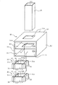
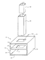
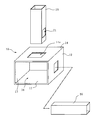
- FIG. 3 is a perspective view before caulking and joining in FIG. 2.
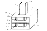
- FIG. 3 is a perspective view after caulking and joining in FIG. 2.
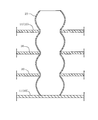
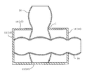
- FIG. 5 is an enlarged cross-sectional view of a caulking region in FIG. 4.
- the perspective view of the 1st modification of the 3rd member which concerns on 1st Embodiment of this invention.
- the perspective view of the 4th modification of the 3rd member concerning a 1st embodiment of the present invention.
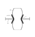
- FIG. 20 is an enlarged cross-sectional view of a joined portion after caulking joining in FIG. 19.
- FIG. 24 is an enlarged cross-sectional view of a joined portion after caulking joining in FIG. 23.
- FIG. 26 is an enlarged cross-sectional view of a joined portion after caulking joining in FIG. 25.
- FIG. 28 is an enlarged cross-sectional view of a joined portion after caulking joining in FIG. 27.
- the material of the individual member is illustrated, but the material of the individual member in all the embodiments is not limited to those specifically illustrated, and the present invention is applied to any material. Is applicable.
- the caulking joining method of the present embodiment joins a steel part (first member) 10 and an aluminum pipe (second member) 20.
- a steel part (first member) 10 an aluminum pipe (second member) 20, and a support part (third member) 30 are prepared.
- the steel part 10 is a square tube made of high-tension steel and having an axis L1 extending in the front-rear direction in FIG.
- the steel part 10 includes a horizontal bottom wall 11, two side walls 12 and 13 rising vertically upward from the bottom wall 11, a horizontal top wall 14 connecting the upper ends of the two side walls 12 and 13, and a bottom wall 11 and the top wall 14 are provided with a horizontal partition wall 15 connecting the two side walls 12 and 13.
- the top wall 14 and the partition wall 15 are provided with square insertion holes (first insertion holes) 14a and 15a, respectively.
- the insertion holes 14a and 15a are provided so as to overlap in a plan view. That is, the insertion holes 14a and 15a are aligned in the horizontal direction.
- a space 17 a having openings 16 at both ends is defined by the top wall 14, the side walls 12 and 13, and the partition wall 15.
- the partition wall 15, the side walls 12, 13 and the bottom wall 11 define a space 17 b having openings 16 at both ends. Therefore, the steel component 10 is formed so that the support component 30 can be inserted into the spaces 17a and 17b from the opening 16 as described later.
- the aluminum pipe 20 of the present embodiment is a hollow tube made of an aluminum alloy, and is a square tube having both ends opened with its axis L2 extending in the vertical direction. No openings are provided in the peripheral walls 20a, 20b, 20c, and 20d of the aluminum pipe 20.
- the aluminum pipe 20 is similar to the shape of the insertion holes 14a and 15a and slightly smaller than the insertion holes 14a and 15a so that the aluminum pipe 20 can be inserted into the insertion holes 14a and 15a of the steel part 10. ing.
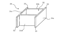
- the support component 30 includes four peripheral walls 31a to 31d made of an aluminum alloy.
- the support component 30 has a hollow shape including an insertion hole 32 defined by the peripheral walls 31a to 31d at the center, and the axis L3 thereof is disposed so as to extend in parallel with the axis L2 of the aluminum pipe 20.
- the support component 30 of the present embodiment is provided with flange portions 33 in which the peripheral walls 31a to 31d extend outward from the insertion holes 32, that is, they are generally # -shaped in plan view.
- the height of the support part 30 is a height that can be inserted between the bottom wall 11 and the partition wall 15 of the steel part 10 and between the partition wall 15 and the top wall 14.
- the steel part 10, the aluminum pipe 20, and the support part 30 are placed in a combined state in a press machine or the like (not shown). The details of the combination will be described in order.
- the support parts 30 are inserted between the bottom wall 11 and the partition wall 15 and between the partition wall 15 and the top wall 14 of the steel part 10, respectively.
- the ten insertion holes 14a and 15a and the insertion hole 32 of the support component 30 are arranged so as to be aligned in plan view.
- the aluminum pipe 20 is inserted into the insertion holes 14a and 15a of the steel part 10 and the insertion holes 32 of the support part 30 and placed on the bottom wall 11, whereby the combination before caulking and joining is completed.
- an elastic body 40 is inserted into the aluminum pipe 20 in order to crimp and join the steel part 10, the aluminum pipe 20, and the support part 30 together.
- the elastic body 40 is made of a rubber material and has a quadrangular prism shape extending in the vertical direction whose dimensions are determined so as to be inserted into the aluminum pipe 20.
- the aluminum pipe 20 is enlarged and deformed and joined to the steel part 10 and the support part 30 by caulking.
- a portion of the aluminum pipe 20 other than the joint 1 with the steel part 10 bulges and is caulked and joined to the steel part 10.
- the caulking is performed in a state where at least a part of the support component 30 is disposed in the caulking region.
- the caulking region refers to the joint 1 between the steel part 10 and the aluminum pipe 20 and the vicinity thereof. Therefore, the aluminum pipe 20 is deformed along the inner surface of the insertion hole 32 of the support component 30, that is, pressed against the inner surface of the support component 30 and caulked and joined to the support component 30.
- the support component 30 is disposed adjacent to the joint 1 between the steel component 10 and the aluminum pipe 20.
- the upper end surface of the support component 30 and the lower surface of the top wall 14 of the steel component 10 are in contact with each other, and the lower end surface of the support component 30 and the upper surface of the partition wall 15 of the steel component 10 are
- the support component 30 is disposed in the caulking region so as to come into contact. Further, the upper end surface of the support component 30 and the lower surface of the partition wall 15 of the steel component 10 are in contact with each other, and the lower end surface of the support component 30 and the upper surface of the bottom wall 11 of the steel component 10 are in contact with each other.
- the support component 30 is disposed in the caulking region.
- the joining strength can be improved while suppressing an increase in the weight of the member in the method of joining the members by caulking.
- the joint strength is a concept including pullout strength, bending strength, and fatigue strength.
- the support component 30 is arranged in the caulking region as described above, the aluminum pipe 20 is prevented from coming off from the steel component 10 as a retaining member, or the steel component 10 or aluminum is used as a reinforcing material.
- the load applied to the pipe 20 can be reduced. Therefore, the joining strength can be improved without increasing the plate thickness of the steel part 10 or the aluminum pipe 20, and the supporting part 30 only needs to be disposed in the vicinity of the joining part 1, so that the weight increase can be minimized.
- the steel part 10 by further caulking and joining the aluminum pipe 20 and the support part 30, the steel part 10, the aluminum pipe 20 and the support part 30 are caulked and joined together, and the joining strength can be further improved.
- the support component 30 also plays a role as a reinforcing material in the vicinity of the joint 1, bending strength and fatigue strength are improved.
- the force is transmitted from the aluminum pipe 20 to the wide area of the steel part 10 including the joint 1 through the support part 30 as compared with the case where there is no support part 30. Therefore, stress is not concentrated. Therefore, the deformation of the steel part 10 can be suppressed, and the aluminum pipe 20 can be more effectively prevented from coming off the steel part 10 along with the deformation.
- the expansion deformation of the aluminum pipe 20 using the elastic body 40 has been described, but the aspect is not particularly limited.
- the aluminum pipe 20 may be expanded and deformed by electromagnetic forming, tube expansion processing using a mandrel or a mold, or the like. The same applies to the following second to fourth embodiments.
- bumper members for automobiles and the like can be cited. That is, the steel part 10 is a bumper member for an automobile, the aluminum pipe 20 is a support pipe connected to the bumper member for an automobile, and the support part 30 is a reinforcing part used with these parts. Take as an example.
- FIGS. 6 to 9 there are shapes shown in FIGS. 6 to 9 in plan view.
- FIG. 6 shows a pure square tube-type support component 30 that does not have the flange portion 33.
- FIG. 7 shows a flange portion 33 in which two peripheral walls 31a and 31c of the four peripheral walls 31a to 31d forming the insertion hole 32 extend outward beyond the two peripheral walls 31b and 31d, respectively.
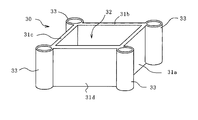
- FIG. 8 shows a support component 30 in which circular flange portions 33 are provided at corners of the four peripheral walls 31a to 31d that form the insertion holes 32.
- FIG. 9 shows a support component 30 in which concentric rectangular tubes similar to each other are connected at each corner.
- FIG. 10 The joining method of the present embodiment shown in FIG. 10 is the same as that of the first embodiment of FIGS. 1 to 5 except for the portion related to the support component 30. Therefore, the same components as those shown in FIGS. 1 to 5 are denoted by the same reference numerals and description thereof is omitted.
- the support component 30 of the present embodiment is a square tube type that is arranged so that its axis L3 extends in a direction different from the axis L2 of the aluminum pipe 20 (in the present embodiment, the front-rear direction).
- the support component 30 includes a horizontal upper wall 34, a horizontal lower wall 35, and two vertical side walls 36 and 37 that connect them.
- the upper wall 34 and the lower wall 35 are provided with rectangular insertion holes 34a and 35a, respectively.
- the rectangular insertion holes 34a and 35a are formed to be similar to the outer shape of the aluminum pipe 20 and slightly larger than the outer shape of the aluminum pipe 20 so that the aluminum pipe 20 can be inserted.
- the support part When combining the steel part 10, the aluminum pipe 20, and the support part 30, the support part is provided between the bottom wall 11 and the partition wall 15 and between the partition wall 15 and the top wall 14 of the steel part 10. 30 and 30 are inserted, respectively, so that the insertion holes 14a and 15a of the steel part 10 and the insertion holes 34a and 35a of the support part 30 are aligned in a plan view.
- the aluminum pipe 20 is inserted into the insertion holes 14 a and 15 a of the steel part 10 and the insertion holes 34 a and 35 a of the support part 30 and placed on the bottom wall 11. From this state, the aluminum pipe 20 is expanded and deformed by using an elastic body or the like as in the first embodiment, and caulked and joined to the steel part 10 and the support part 30.
- the aluminum pipe 20 is swollen except for the joint 1 with the steel part 10 and the joint 1 with the support part 30, and is caulked and joined with the steel part 10 and the support part 30. At this time, the support component 30 and the steel component 10 are in surface contact within the caulking region.
- the bending strength can be improved particularly in the caulking region.
- the support part 30 supports the steel part 10 with the surface in the caulking region, so that the same bending strength as when the plate thickness of the steel part 10 is increased in the caulking area can be obtained.
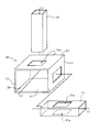
- the aspect of the present embodiment is not limited to the aspect illustrated in FIG. 10, and the support component 30 may be disposed outside the steel component 10 as illustrated in FIG. 12. In such a case, it is preferable that the steel part 10 does not have the partition wall 15.
- the support component 30 and the steel component 10 need to be in surface contact within the caulking region. This is because the support component 30 cannot contact the inner partition wall of the steel component 10 when arranged outside the steel component 10.
- FIGS. 13 to 18 there are the shapes shown in FIGS. 13 to 18 in a front view.
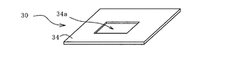
- FIG. 13 shows a plate-like support component 30 composed only of the upper wall 34.
- Shown in FIG. 14 is a channel-type support component 30 further comprising side walls 36, 37.
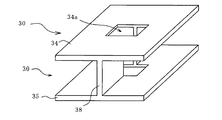
- FIG. 15 shows an H-shaped support component 30 that includes an upper wall 34, a lower wall 35, and an intermediate wall 38 that connects them in the longitudinal direction at the center.
- FIG. 16 shows a support component 30 in which an intermediate wall 39 extending in the lateral direction at the center is further provided with respect to the H-shaped support component 30 of FIG.
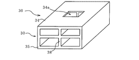
- FIG. 17 shows an intermediate wall 38 that connects the upper wall 34 and the lower wall 35 of the square-shaped support component 30 in the vertical direction at the center, and an intermediate wall 39 that connects the side walls 36 and 37 in the horizontal direction at the center. It is the support component 30 provided with these.
- FIG. 18 shows a circular support component 30.
- the top wall 14, the partition wall 15, and the bottom wall 11 of the steel part 10 need to have corresponding curved shapes.
- Such a modification includes a case where the support component 30 does not have a point-symmetric structure and the axis L3 (see FIG. 10) cannot be accurately defined. In this case, the axis L3 has a center of gravity. Define to pass.
- the support component 30 of this embodiment is a square tube type that is arranged so that its axis L3 extends in a direction parallel to the axis L2 of the aluminum pipe 20 (in the present embodiment, coincides).
- the support component 30 has a rectangular outer shape that is similar to the inner shape of the aluminum pipe 20 and is slightly smaller than the inner shape of the aluminum pipe 20 so as to be inserted into the aluminum pipe 20.
- At least a part of the support component 30 is arranged in the same plane as the joint 1 of the steel component 10 and the aluminum pipe 20, and the support component 30 and the aluminum pipe 20 are in the caulking region. Surface contact.
- the support part 30 is deformed along the aluminum pipe 20, is enlarged and deformed together with the aluminum pipe 20, and is caulked and joined to the steel part 10.
- the bending strength can be improved particularly in the caulking region.
- the support part 30 supports the aluminum pipe 20 with the surface in the caulking region, so that the same bending strength as that obtained when the thickness of the aluminum pipe 20 is increased in the caulking region can be obtained.
- the support component 30 may be disposed outside the aluminum pipe 20. That is, the support component 30 may be disposed between the steel component 10 and the aluminum pipe 20.
- the steel part 10 and the support part 30 are made of the same material (for example, high-tension steel), and an insulating adhesive (insulating material) 41 is interposed between the aluminum pipe 20 and the support part 30.
- the adhesive 41 only needs to have insulating properties, and the type thereof is not particularly limited, and may be, for example, a foaming agent. Further, as illustrated in FIG. 22, the adhesive 41 may be disposed only at the end portion of the support member 30.
- the method of this modification it is possible to prevent electrolytic corrosion occurring between different kinds of metals. Specifically, by using the same kind of material for the steel part 10 and the support part 30, no electrolytic corrosion that occurs between different metals occurs between the steel part 10 and the support part 30. Even if the aluminum pipe 20 and the support component 30 are made of different materials, since the adhesive 41 is interposed between the aluminum pipe 20 and the support component 30, it is possible to prevent electrolytic corrosion between them. In particular, when the steel part 10 and the aluminum pipe 20 are different materials and the steel part 10 and the aluminum pipe 20 are in contact at either end, an adhesive is applied to such an end to It is difficult to prevent erosion, and it is effective to prevent galvanic corrosion via the support component 30 as in this method.
- the adhesive 41 is not disposed in all the gaps between the aluminum pipe 20 and the support component 30 but is disposed so as to seal the gap at the end of the support component 30 (see FIG. 22). Water and air can be prevented from entering the gap, and electric corrosion countermeasures are possible.
- the support component 30 may be a sheet, and the support component 30 may be wound around the aluminum pipe 20 to be caulked and joined.
- the application target is not limited by the shape of the support component 30 because the support component 30 is in the form of a sheet. Further, the support component 30 can be wound around an arbitrary range, and can be disposed at a portion unrelated to the bonding strength to prevent the weight from increasing more than necessary. In addition, the weight and bonding strength can be changed by changing the winding thickness, which is applicable.
- (Fourth embodiment) 25 and 26 is the same as that of the second embodiment of FIGS. 10 to 11 except for the portion related to the insertion direction of the support component 30. Therefore, the same components as those shown in FIGS. 10 to 11 are denoted by the same reference numerals and the description thereof is omitted.
- the steel component 10 of the present embodiment is hollow and has an insertion hole (second insertion hole) 12a for inserting the support component 30 in the side wall 12.
- the partition wall is not provided in the steel part 10, but may be provided.
- the support component 30 of this embodiment is a hollow square tube type.
- the support component 30 is arranged such that its axis L3 extends in a direction different from the axis L1 of the steel component 10 and the axis L2 of the aluminum pipe (in this embodiment, a direction orthogonal to the axes L1 and L2).
- the support component 30 has rectangular insertion holes 34a and 35a similar to the outer shape of the aluminum pipe 20 and slightly larger than the outer shape of the aluminum pipe 20 so that the aluminum pipe 20 can be inserted into the upper wall 34 and the lower wall 35, respectively. Is provided.
- the support part 30 is inserted into the steel part 10, and the aluminum pipe 20 is inserted into the steel part 10 and the support part 30, followed by caulking.
- the support part 30 is inserted into the insertion hole 14a of the steel part 10, and the aluminum pipe 20 is inserted into the insertion hole 14a of the steel part 10 and the insertion holes 34a and 35a of the support part 30.
- the steel part 10 and the support part 30 are caulked and joined by being enlarged and deformed.
- the pulling force and bending force applied to the aluminum pipe 20 are transmitted to both the steel component 10 and the support component 30, so that the pulling force and bending force are not concentrated, and the joint 1
- the joint strength is improved.
- the support component 30 may not have an insertion hole.
- an insertion hole 21 for inserting the support component 30 into the aluminum pipe 20 is provided.
- the aluminum pipe 20 is inserted into the steel part 10 and the support part 30 is inserted into the steel part 10 and the aluminum pipe 20 and then caulked and joined. That is, in the joining method of this modification, first, the aluminum pipe 20 is inserted into the insertion hole 14a of the steel part 10, the aluminum pipe 20 is enlarged and deformed, and the aluminum pipe 20 is caulked and joined to the steel part 10.
- the support part 30 is inserted into the insertion hole 14 a of the steel part 10 and the insertion hole 21 of the aluminum pipe 20, the support part 30 is enlarged and deformed, and the support part 30 is changed into the steel part 10 and the aluminum pipe 20. Caulking and joining.
- the aluminum pipe 20 is caulked and joined to the steel part 10 and the support part 30 is caulked and joined to the aluminum pipe 20, it can be caulked and joined at at least two locations, and the joining strength can be improved.
- an adhesive 41 is used between different kinds of metal materials as shown in FIGS. 21 and 22 through the first to fourth embodiments. That is, when the steel part (first member) 10, the aluminum pipe (second member) 20, and the support part (third member) 30 are formed of different materials, between at least one different material, Or it is preferable that the adhesive agent (insulating material) is arrange
- the insertion holes 14a and 15a of the steel part 10 and the outer shape of the aluminum pipe 20 are similar.
- both are quadrangular and similar, but the present invention is not limited thereto, and may be polygonal or circular and similar.
Landscapes
- Engineering & Computer Science (AREA)
- Mechanical Engineering (AREA)
- General Engineering & Computer Science (AREA)
- Connection Of Plates (AREA)
Abstract
本発明の部材の接合方法では、挿入穴14a,15aを有する鋼製部品10と、中空状のアルミパイプ20と、支持部品30とを準備し、鋼製部品10の挿入穴14a,15aにアルミパイプ20を挿入し、アルミパイプ20を拡大変形させてアルミパイプ20を鋼製部品10にかしめ接合することを含む。このとき、かしめ接合は、かしめ領域に少なくとも支持部品30の一部が配置された状態で行われる。
Description
本発明は、部材の接合方法に関する。
自動車の構造部材では、ハイテンション鋼と呼ばれる高強度の薄鋼板が使用されている。これらのハイテンション鋼は軽量化や安全性向上に有効ではあるが、アルミなどの低比重材料と比べると重い。また、ハイテンション鋼には、高強度ゆえに、成形性の低下、成形荷重の上昇、および寸法精度の低下などの問題がある。これらの問題を解決するために、近年、鋼板よりも比重が軽いアルミを用いた押し出し成形品や鋳造品、プレス成形品を鋼製部品と合わせて活用するマルチマテリアル化が行われている。
マルチマテリアル化で問題となるのは鋼板製部品とアルミ部品の接合である。スポット溶接に代表される溶接技術においては鋼板とアルミ板の界面に脆弱な金属間化合物(IMC:intermetallic compound)が生じるため、電磁成形接合、ボルトとナットに代表されるねじ締結、摩擦撹拌接合(FSW:friction stir welding)、リベット、セルフピアスリベット(SPR:self-piercing rivet)、メカニカルクリンチング、および接着などの接合技術が実用化されている。
電磁成形によるかしめは、相手部品に嵌合させたパイプ状の部品の内側にソレノイド成形コイルを挿入し、コイルに衝撃電流を流すことによって生じる磁界の変化により、導体のパイプに誘導電流を誘起させる。コイルの1次電流による磁界と、パイプの周方向上に反対方向に流れる誘導電流との間に電磁力が発生し、このときパイプは外側に向かう力を受けるため拡大変形され相手部品にかしめ接合される。この接合方法は、電気伝導度の良い銅やアルミに適しており、自動車部品の接合においても一部で実用化されている。
特許文献1には、マルチマテリアル化のための電磁成形によるかしめ接合技術が開示されている。特許文献1では、断面が中空の金属形材からなるバンパーリインフォースを電磁成形により拡大変形し、アルミニウム合金製のバンパーステイに設けられた穴部と嵌合させて接合している。
特許文献1の電磁成形やその他の接合方法において、接合強度の向上が望まれている。接合強度の向上のためには、部材強度を向上させることが好ましい。そのためには、材料の高硬度化や板厚の増加が考えられる。しかし、部材の高硬度化に伴って衝撃時の割れの危険性が増大したり、板厚の増加に伴って部品重量が増加したりする。代替的には、接合強度の向上のために接合部にバーリング等の加工を施すことも考えられるが、接合部の形状によってはバーリング加工が難しい場合がある。また、バーリング加工可能な形状であっても、加工により工数が増加し、製造コストが増大する。
本発明は、かしめ接合による部材の接合方法において、部材の重量増加を抑制しつつ、接合強度を向上させることを課題とする。
本発明の部材の接合方法は、第1挿入穴を有する第1部材と、中空状の第2部材と、第3部材とを準備し、前記第1部材の前記第1挿入穴に前記第2部材を挿入し、前記第2部材を拡大変形させて前記第2部材を前記第1部材にかしめ接合することを含み、前記かしめ接合は、かしめ領域に少なくとも前記第3部材の一部が配置された状態で行われること含んでいる。
この方法によれば、かしめ接合による部材の接合方法において、部材の重量増加を抑制しつつ、接合強度を向上できる。接合強度は、引抜強度と曲げ強度と疲労強度とを含む概念である。具体的には、かしめ領域に第3部材を配置しているので、抜け止めとして第2部材が第1部材から抜けるのを防止したり、補強材として第1部材や第2部材にかかる負荷を軽減したりできる。そのため、第1部材や第2部材の板厚を増加させることなく接合強度を向上でき、かしめ領域にのみ第3部材を配置すればよいため、重量増加を最小限にできる。ここで、かしめ領域とは、第1部材と第2部材の接合部およびその近傍のことをいう。
前記第2部材と前記第3部材をさらにかしめ接合してもよい。
前記第2部材と前記第3部材をさらにかしめ接合することで、第1部材と第2部材と第3部材とが一体としてかしめ接合され、接合強度をさらに向上できる。
前記第3部材を、前記第1部材と前記第2部材の接合部に隣接して配置していてもよい。
接合部に隣接して第3部材が配置されていることで、第2部材に引抜力が付加された際、第3部材が抜け止めとしての役割を果たすため、引抜強度を向上できる。また、第3部材は、接合部の近傍で補強材としての役割も果たすため、曲げ強度と疲労強度も向上する。
前記第3部材は、挿通穴を備える中空状であり、前記第3部材を、軸線が前記第2部材の軸線と平行に延びるように配置し、前記第3部材の前記挿通穴に前記第2部材を挿入してかしめ接合してもよい。
この方法によれば、特に引抜強度を向上できる。第2部材に引抜力が付加された際、第3部材がない場合に比べて、第2部材から第3部材を介して接合部を含む第1部材の広い領域に力が伝達されるため、応力が集中しない。そのため、第1部材の変形を抑制でき、変形に伴って第2部材が第1部材から抜けることを防止できる。
前記第3部材を、前記第3部材と前記第1部材が前記かしめ領域内で面接触するように、かつ、軸線が前記第2部材の軸線とは異なる方向に延びるように配置してもよい。
この方法によれば、特にかしめ領域における曲げ強度を向上できる。第3部材がかしめ領域内で第1部材を面で支持することで、かしめ領域内で第1部材の板厚を増加させた場合と同様の曲げ強度を向上できる効果が得られる。
前記第3部材の少なくとも一部を、前記第3部材と前記第2部材が前記かしめ領域内で面接触するように、前記第1部材と前記第2部材の接合部と同一平面内に配置してもよい。
この方法によれば、特にかしめ領域における曲げ強度を向上できる。第3部材がかしめ領域内で第2部材を面で支持することで、かしめ領域内で第2部材の板厚を増加させた場合と同様の曲げ強度を向上できる効果が得られる。
前記第1部材と前記第3部材は同種の材料であり、前記第3部材を前記第2部材の外側に配置し、前記第2部材と前記第3部材の間には絶縁材を介在させてもよい。
この方法によれば、異種金属間で生じる電食を防止できる。具体的には、第1部材と第3部材を同種の材料にすることで、第1部材と第3部材の間には異種金属間で生じる電食が生じない。第2部材と第3部材は異種の材料であっても、第2部材と第3部材の間には接着剤が介在しているため、これらの間の電食を防止できる。特に、第1部材と第2部材が異種の材料であって、第1部材と第2部材がいずれかの端部で接触する場合、そのような端部に接着材を塗布して電食を防止することは難しく、本方法のように第3部材を介して電食を防止することが有効である。
前記第3部材はシート状であり、前記第3部材を前記第2部材の周囲に巻き付けてもよい。
第3部材がシート状であることで、第3部材の形状によって適用対象が限定されることがない。また、任意の範囲に第3部材を巻きつけることができ、接合強度とは無関係な部分に配置して重量が必要以上に増加することを防止できる。また、巻きつける厚みの変更によって重量や接合強度を変更でき、応用性がある。
前記第1部材は、中空状であり、第2挿入穴を有し、前記第3部材は、中空状であり、前記第3部材を前記第1部材の前記第2挿入穴に挿入し、前記第2部材を拡大変形させ、前記第2部材を前記第1部材にかしめ接合してもよい。
この方法によれば、第2部材に加わる引抜力や曲げ力が、第1部材と第3部材の両方に伝達されるので、引抜力や曲げ力が集中せず、接合部の接合強度が向上する。
さらに前記第3部材を拡大変形させ、前記第3部材を前記第2部材にかしめ接合してもよい。
この方法によれば、第2部材を第1部材にかしめ接合すると共に、第3部材を第2部材にかしめ接合するため、少なくとも2箇所でかしめ接合でき、接合強度を向上できる。
前記第1部材と、前記第2部材と、前記第3部材との少なくともいずれかの間、または少なくともいずれかの端部に絶縁材を配置してもよい。
この方法によれば、絶縁材によって異種金属間で生じる電食を防止できる。
前記第1部材の前記第1挿入穴と、前記第2部材の外形とは相似形であってもよい。
この方法によれば、かしめ接合時の第2部材の拡大変形量を最小限にでき、第2部材に対する負荷を軽減し、割れや意図しない変形を防止できる。
本発明によれば、かしめ接合による第1部材と第2部材の接合方法において、第3部材を使用することで、部材の重量増加を抑制しつつ、接合強度を向上できる。
以下、添付図面を参照して本発明の実施形態を説明する。
以下で説明する各実施形態では、個々の部材の材料を例示しているが、全実施形態において個々の部材の材料は特に例示しているものに限定されず、任意の材料に対して本発明は適用できる。
(第1実施形態)
図1を参照すると、本実施形態のかしめ接合方法は、鋼製部品(第1部材)10とアルミパイプ(第2部材)20を接合するものである。このかしめ接合方法では、まず、鋼製部品(第1部材)10と、アルミパイプ(第2部材)20と、支持部品(第3部材)30とを準備する。
図1を参照すると、本実施形態のかしめ接合方法は、鋼製部品(第1部材)10とアルミパイプ(第2部材)20を接合するものである。このかしめ接合方法では、まず、鋼製部品(第1部材)10と、アルミパイプ(第2部材)20と、支持部品(第3部材)30とを準備する。
鋼製部品10は、ハイテンション鋼からなり、軸線L1が図1において前後方向に延びる四角管である。鋼製部品10は、水平な底壁11と、底壁11から鉛直上方へ立ち上がる2つの側壁12,13と、2つの側壁12,13の上端部を接続する水平な頂壁14と、底壁11と頂壁14との中間で2つの側壁12,13を接続する水平な仕切壁15とを備える。頂壁14と仕切壁15には、四角形の挿入穴(第1挿入穴)14a,15aがそれぞれ設けられている。挿入穴14a,15aは、平面視で重なるように設けられている。即ち、挿入穴14a,15aは、水平方向に位置合わせされている。鋼製部品10では、頂壁14と側壁12,13と仕切壁15とによって、両端に開口部16を有する空間17aが画定されている。また、鋼製部品10では、仕切壁15と側壁12,13と底壁11とによって、両端に開口部16を有する空間17bが画定されている。従って、鋼製部品10は、後述のように開口部16から空間17a,17bに支持部品30を挿入可能に形成されている。
本実施形態のアルミパイプ20は、アルミニウム合金からなる中空状で、その軸線L2が上下方向に延びる両端開口の四角管である。アルミパイプ20の周壁20a,20b,20c,20dには、開口部は設けられていない。平面視において、アルミパイプ20は、鋼製部品10の挿入穴14a,15aに挿入可能なように、挿入穴14a,15aの形状と相似形でわずかに挿入穴14a,15aより小さな外形を有している。
支持部品30は、アルミニウム合金製の4つの周囲壁31a~31dからなる。支持部品30は、中央に周囲壁31a~31dによって画定された挿通穴32を備える中空状であり、その軸線L3がアルミパイプ20の軸線L2と平行に延びるように配置されている。本実施形態の支持部品30は、周囲壁31a~31dが挿通穴32からそれぞれ外側へ向かって延びたフランジ部33が設けられており、即ち平面視において概ね#型である。支持部品30の高さは、鋼製部品10の底壁11と仕切壁15との間および仕切壁15と頂壁14との間に挿入可能な高さである。
図2に示すように、接合前に、鋼製部品10と、アルミパイプ20と、支持部品30とが、組み合わせられた状態で図示しないプレス機等に配置される。組み合わせ方の詳細を順に説明すると、まず、鋼製部品10の底壁11と仕切壁15との間および仕切壁15と頂壁14との間に、支持部品30をそれぞれ挿入し、鋼製部品10の挿入穴14a,15aと、支持部品30の挿通穴32とが平面視において位置合わせされるように配置する。次いで、アルミパイプ20を、鋼製部品10の挿入穴14a,15aと、支持部品30の挿通穴32とに挿入して底壁11に載置することで、かしめ接合前の組み合わせが完了する。
図3に示すように、鋼製部品10と、アルミパイプ20と、支持部品30とが組み合わせられた状態から、これらをかしめ接合するために、アルミパイプ20内に弾性体40を挿入する。弾性体40は、ゴム材質であり、アルミパイプ20内に挿入できるように寸法が決定された上下方向に延びる四角柱状である。
図4に示すように、図3の状態から図示しないプレス装置等の圧子で弾性体40を下方へ押圧すると、弾性体40は上下方向の寸法が縮小するにつれて水平方向の寸法が拡大する。従って、アルミパイプ20は、弾性体40の弾性変形(膨張)に合わせて水平方向に拡大変形される。
このようにして、図5に示すように、鋼製部品10と、支持部品30とに対して、アルミパイプ20を拡大変形させてかしめ接合する。アルミパイプ20は、鋼製部品10との接合部1以外の部分が膨出し、鋼製部品10とかしめ接合される。かしめ接合は、かしめ領域に少なくとも支持部品30の一部が配置された状態で行われる。ここで、かしめ領域とは、鋼製部品10とアルミパイプ20の接合部1およびその近傍のことをいう。そのため、アルミパイプ20は、支持部品30の挿通穴32の内面に沿って変形し、即ち支持部品30の内面に押し付けられて支持部品30とかしめ接合される。支持部品30は、鋼製部品10とアルミパイプ20の接合部1に隣接して配置される。本実施形態では、支持部品30の上端面と、鋼製部品10の頂壁14の下面とが接触し、かつ、支持部品30の下端面と、鋼製部品10の仕切壁15の上面とが接触するように、支持部品30はかしめ領域に配置される。また、支持部品30の上端面と、鋼製部品10の仕切壁15の下面とが接触するように、かつ、支持部品30の下端面と、鋼製部品10の底壁11の上面とが接触するように、支持部品30はかしめ領域に配置される。
本実施形態の方法によれば、かしめ接合による部材の接合方法において、部材の重量増加を抑制しつつ、接合強度を向上できる。接合強度は、引抜強度と曲げ強度と疲労強度とを含む概念である。具体的には、上述のようにかしめ領域に支持部品30を配置しているので、抜け止めとしてアルミパイプ20が鋼製部品10から抜けるのを防止したり、補強材として鋼製部品10やアルミパイプ20にかかる負荷を軽減したりできる。そのため、鋼製部品10やアルミパイプ20の板厚を増加させることなく接合強度を向上でき、接合部1の近傍にのみ支持部品30を配置すればよいため、重量増加を最小限にできる。
また、アルミパイプ20と支持部品30をさらにかしめ接合することで、鋼製部品10とアルミパイプ20と支持部品30とが一体としてかしめ接合され、接合強度をさらに向上できる。
また、支持部品30は、接合部1の近傍で補強材としての役割も果たすため、曲げ強度と疲労強度も向上する。
また、アルミパイプ20に引抜力が付加された際、支持部品30がない場合に比べて、アルミパイプ20から支持部品30を介して接合部1を含む鋼製部品10の広い領域に力が伝達されるため、応力が集中しない。そのため、鋼製部品10の変形を抑制でき、変形に伴ってアルミパイプ20が鋼製部品10から抜けることをより効果的に防止できる。
本実施形態では、弾性体40を利用したアルミパイプ20の拡大変形について説明したが、その態様は特に限定されない。代替的には、例えば、電磁成形、マンドレルや金型を利用した拡管加工等によってアルミパイプ20を拡大変形させてもよい。これは以降の第2から第4実施形態でも同様である。
本実施形態のかしめ接合方法の適用対象例としては、自動車用のバンパー部材等が挙げられる。即ち、鋼製部品10は自動車用のバンパー部材であり、アルミパイプ20は自動車用のバンパー部材に接続される支持パイプであり、支持部品30はこれらと共に使用される補強部品である場合が適用対象例として挙げられる。
また、本実施形態の支持部品30の変形例として、平面視において図6から図9に示す形状が挙げられる。図6に示すのは、フランジ部33を有していない純粋な四角管型の支持部品30である。図7に示すのは、挿通穴32を形成する4つの周囲壁31a~31dのうち、2つの周囲壁31a,31cが2つの周囲壁31b,31dを超えてそれぞれ外側へ延出したフランジ部33を有する支持部品30である。図8に示すのは、挿通穴32を形成する4つの周囲壁31a~31dの角部に円形状のフランジ部33が設けられた支持部品30である。図9に示すのは、互いに相似形の同心の四角管が各角部で接続された支持部品30である。
(第2実施形態)
図10に示す本実施形態の接合方法は、支持部品30に関する部分以外の構成は図1から図5の第1実施形態と同様である。従って、図1から図5に示した構成と同様の部分については同様の符号を付して説明を省略する。
図10に示す本実施形態の接合方法は、支持部品30に関する部分以外の構成は図1から図5の第1実施形態と同様である。従って、図1から図5に示した構成と同様の部分については同様の符号を付して説明を省略する。
本実施形態の支持部品30は、その軸線L3がアルミパイプ20の軸線L2とは異なる方向(本実施形態では前後方向)に延びるように配置された四角管型である。支持部品30は、水平な上壁34と、水平な下壁35と、それらを繋ぐ鉛直な2つの側壁36,37とから構成される。上壁34と下壁35には、四角形の挿通穴34a,35aがそれぞれ設けられている。四角形の挿通穴34a,35aは、アルミパイプ20を挿入可能なように、アルミパイプ20の外形と相似形でアルミパイプ20の外形よりわずかに大きく形成されている。
鋼製部品10と、アルミパイプ20と、支持部品30とを組み合わせる際は、鋼製部品10の底壁11と仕切壁15との間および仕切壁15と頂壁14との間に、支持部品30,30をそれぞれ挿入し、鋼製部品10の挿入穴14a,15aと、支持部品30の挿通穴34a,35aとが平面視において揃えられるように配置する。次いで、アルミパイプ20を、鋼製部品10の挿入穴14a,15aと、支持部品30の挿通穴34a,35aとに挿入し、底壁11に載置する。その状態から第1実施形態と同様に弾性体等を利用して、アルミパイプ20を拡大変形させ、鋼製部品10と支持部品30にかしめ接合する。
図11に示すように、アルミパイプ20は、鋼製部品10との接合部1および支持部品30との接合部1以外で膨出し、鋼製部品10および支持部品30とかしめ接合されている。このとき、支持部品30と鋼製部品10は、かしめ領域内で面接触している。
本実施形態の方法によれば、特にかしめ領域における曲げ強度を向上できる。支持部品30がかしめ領域内で鋼製部品10を面で支持することで、かしめ領域内で鋼製部品10の板厚を増加させた場合と同様の曲げ強度を向上できる効果が得られる。
本実施形態の態様は、図10に示されている態様に限定されず、図12に示されているように、支持部品30が鋼製部品10の外側に配置されてもよい。そのような場合、鋼製部品10は、仕切壁15を有していない方が好ましい。上述のように、支持部品30を鋼製部品10の補強に使用するためには、支持部品30と鋼製部品10は、かしめ領域内で面接触している必要があるが、支持部品30が鋼製部品10の外側に配置された場合、支持部品30は鋼製部品10の内側の仕切壁とは接触できないためである。
本実施形態の支持部品30の変形例として、正面視において図13から図18に示す形状が挙げられる。図13に示すのは、上壁34のみからなる板状の支持部品30である。図14に示すのは、さらに側壁36,37を備えるチャネル型の支持部品30である。図15に示すのは、上壁34と、下壁35と、それらを中央で縦方向に接続する中間壁38とを備えるH型の支持部品30である。図16に示すのは、図15のH型の支持部品30に対して、中央で横方向に延びる中間壁39がさらに設けられた支持部品30である。図17に示すのは、四角型の支持部品30の上壁34と下壁35とを中央で縦方向に接続する中間壁38と、側壁36,37を中央で横方向に接続する中間壁39とを備える支持部品30である。図18に示すのは、円形の支持部品30である。円形の支持部品30を使用する場合、鋼製部品10の頂壁14と仕切壁15と底壁11とは、対応する湾曲形状を有している必要がある。なお、このような変形例には、支持部品30が点対称構造を有しておらず軸線L3(図10参照)が正確に定義できない場合を含んでいるが、その場合の軸線L3は重心を通るように定義する。
(第3実施形態)
図19に示す本実施形態の接合方法は、支持部品30に関する部分以外の構成は図1から図5の第1実施形態と同様である。従って、図1から図5に示した構成と同様の部分については同様の符号を付して説明を省略する。
図19に示す本実施形態の接合方法は、支持部品30に関する部分以外の構成は図1から図5の第1実施形態と同様である。従って、図1から図5に示した構成と同様の部分については同様の符号を付して説明を省略する。
本実施形態の支持部品30は、その軸線L3がアルミパイプ20の軸線L2と平行な方向(本実施形態では一致)に延びるように配置された四角管型である。支持部品30は、アルミパイプ20に挿入可能なように、アルミパイプ20の内形と相似形でわずかにアルミパイプ20の内形より小さな四角形の外形を有している。
図20に示すように、支持部品30の少なくとも一部は、鋼製部品10とアルミパイプ20の接合部1と同一平面内に配置されており、支持部品30とアルミパイプ20がかしめ領域内で面接触している。支持部品30は、アルミパイプ20に沿って変形されており、アルミパイプ20と共に拡大変形されて鋼製部品10にかしめ接合されている。
本実施形態の方法によれば、特にかしめ領域における曲げ強度を向上できる。支持部品30がかしめ領域内でアルミパイプ20を面で支持することで、かしめ領域内でアルミパイプ20の板厚を増加させた場合と同様の曲げ強度を向上できる効果が得られる。
図21に示すように、本実施形態の変形例として、支持部品30は、アルミパイプ20の外側に配置されてもよい。即ち、支持部品30は、鋼製部品10とアルミパイプ20との間に配置されてもよい。その場合、鋼製部品10と支持部品30は同種の材料(例えばハイテンション鋼)とし、アルミパイプ20と支持部品30の間には絶縁性の接着剤(絶縁材)41が介在していることが好ましい。接着剤41は、絶縁性を有していればよく、その種類は特に限定されず、例えば発泡剤であってもよい。また、図22に示すように、接着剤41は、支持部材30の端部にのみ配置されていてもよい。
本変形例の方法によれば、異種金属間で生じる電食を防止できる。具体的には、鋼製部品10と支持部品30を同種の材料にすることで、鋼製部品10と支持部品30の間には異種金属間で生じる電食が生じない。アルミパイプ20と支持部品30は異種の材料であっても、アルミパイプ20と支持部品30の間には接着剤41が介在しているため、これらの間の電食を防止できる。特に、鋼製部品10とアルミパイプ20が異種の材料であって、鋼製部品10とアルミパイプ20がいずれかの端部で接触する場合、そのような端部に接着材を塗布して電食を防止することは難しく、本方法のように支持部品30を介して電食を防止することが有効である。また、接着剤41は、アルミパイプ20と支持部品30の間の隙間の全てに配置せず、支持部品30の端部に該隙間を封止するように配置した場合(図22参照)でも、該隙間への水や空気の浸入を防止でき、電食対策は可能である。
図23,24に示すように、本実施形態の他の変形例として、支持部品30がシート状であり、支持部品30をアルミパイプ20の周囲に巻き付けてかしめ接合してもよい。
支持部品30がシート状であることで、支持部品30の形状によって適用対象が限定されることがない。また、任意の範囲に支持部品30を巻きつけることができ、接合強度とは無関係な部分に配置して重量が必要以上に増加することを防止できる。また、巻きつける厚みの変更によって重量や接合強度を変更でき、応用性がある。
(第4実施形態)
図25,26に示す本実施形態の接合方法は、支持部品30の挿入方向に関する部分以外の構成は図10から図11の第2実施形態と同様である。従って、図10から図11に示した構成と同様の部分については同様の符号を付して説明を省略する。
図25,26に示す本実施形態の接合方法は、支持部品30の挿入方向に関する部分以外の構成は図10から図11の第2実施形態と同様である。従って、図10から図11に示した構成と同様の部分については同様の符号を付して説明を省略する。
本実施形態の鋼製部品10は、中空状であり、側壁12に支持部品30を挿入するための挿入穴(第2挿入穴)12aを有する。本実施形態では、鋼製部品10に仕切壁は設けられていないが、設けられていてもよい。
本実施形態の支持部品30は、中空状の四角管型である。支持部品30は、その軸線L3が、鋼製部品10の軸線L1と、アルミパイプの軸線L2とは異なる方向(本実施形態では軸線L1,L2に直交する方向)に延びるように配置されている。支持部品30は、上壁34と下壁35にアルミパイプ20を挿入可能なように、アルミパイプ20の外形と相似形でわずかにアルミパイプ20の外形より大きな四角形の挿通穴34a,35aがそれぞれ設けられている。接合の際、支持部品30を鋼製部品10に挿入し、アルミパイプ20を鋼製部品10と支持部品30に挿入した後、かしめ接合する。即ち、支持部品30を鋼製部品10の挿入穴14aに挿入し、アルミパイプ20を鋼製部品10の挿入穴14aと、支持部品30の挿通穴34a,35aとに挿入し、アルミパイプ20を拡大変形させて鋼製部品10と支持部品30にかしめ接合する。
本実施形態の方法によれば、アルミパイプ20に加わる引抜力や曲げ力が、鋼製部品10と支持部品30の両方に伝達されるので、引抜力や曲げ力が集中せず、接合部1の接合強度が向上する。
図27,28に示すように、本実施形態の変形例として、支持部品30は、挿通穴を有していなくてもよい。その場合、アルミパイプ20に支持部品30挿通するための挿通穴21が設けられる。接合の際、アルミパイプ20を鋼製部品10に挿入し、支持部品30を鋼製部品10とアルミパイプ20に挿入した後、かしめ接合する。即ち、本変形例の接合方法では、まず、アルミパイプ20を鋼製部品10の挿入穴14aに挿入し、アルミパイプ20を拡大変形させ、アルミパイプ20を鋼製部品10にかしめ接合する。次に、支持部品30を鋼製部品10の挿入穴14aと、アルミパイプ20の挿通穴21とに挿入し、支持部品30を拡大変形させ、支持部品30を鋼製部品10とアルミパイプ20にかしめ接合する。
本変形例の方法によれば、アルミパイプ20を鋼製部品10にかしめ接合すると共に、支持部品30をアルミパイプ20にかしめ接合するため、少なくとも2箇所でかしめ接合でき、接合強度を向上できる。
また、第1から第4実施形態を通じて、異種金属材料間では図21,22に示すように接着剤41が使用されていることが好ましい。即ち、鋼製部品(第1部材)10と、アルミパイプ(第2部材)20と、支持部品(第3部材)30とが異種材料で形成されている場合、少なくとも1つの異種材料間に、または少なくとも1つの部材の端部に異種材料間の隙間を封止するように接着剤(絶縁材)が配置されていることが好ましい。これにより、接着剤(絶縁材)によって異種金属間で生じる電食を防止できる。
また、第1から第4実施形態を通じて、鋼製部品10の挿入穴14a,15aと、アルミパイプ20の外形とは、相似形であることが好ましい。本実施形態では、共に四角形で相似形であったが、これに限らず、多角形や円形で相似形であってもよい。これにより、かしめ接合時のアルミパイプ20の拡大変形量を最小限にでき、アルミパイプ20に対する負荷を軽減し、割れや意図しない変形を防止できる。
1 接合部
10 鋼製部品(第1部材)
11 底壁
12,13 側壁
12a 挿入穴(第2挿入穴)
14 頂壁
14a 挿入穴(第1挿入穴)
15 仕切壁
15a 挿入穴(第1挿入穴)
16 開口部
17a,17b 空間
20 アルミパイプ(第2部材)
21 挿通穴
30 支持部品(第3部材)
31a,31b,31c,31d 周囲壁
32 挿通穴
33 フランジ部
34 上壁
34a 挿通穴
35 下壁
35a 挿通穴
36,37 側壁
38,39 中間壁
40 弾性体
41 接着剤(絶縁材)
10 鋼製部品(第1部材)
11 底壁
12,13 側壁
12a 挿入穴(第2挿入穴)
14 頂壁
14a 挿入穴(第1挿入穴)
15 仕切壁
15a 挿入穴(第1挿入穴)
16 開口部
17a,17b 空間
20 アルミパイプ(第2部材)
21 挿通穴
30 支持部品(第3部材)
31a,31b,31c,31d 周囲壁
32 挿通穴
33 フランジ部
34 上壁
34a 挿通穴
35 下壁
35a 挿通穴
36,37 側壁
38,39 中間壁
40 弾性体
41 接着剤(絶縁材)
Claims (12)
- 第1挿入穴を有する第1部材と、中空状の第2部材と、第3部材とを準備し、
前記第1部材の前記第1挿入穴に前記第2部材を挿入し、
前記第2部材を拡大変形させて前記第2部材を前記第1部材にかしめ接合することを含み、
前記かしめ接合は、かしめ領域に少なくとも前記第3部材の一部が配置された状態で行われる、部材の接合方法。 - 前記第2部材と前記第3部材をさらにかしめ接合する、請求項1に記載の部材の接合方法。
- 前記第3部材を、前記第1部材と前記第2部材の接合部に隣接して配置する、請求項1または請求項2に記載の部材の接合方法。
- 前記第3部材は、挿通穴を備える中空状であり、
前記第3部材を、軸線が前記第2部材の軸線と平行に延びるように配置し、
前記第3部材の前記挿通穴に前記第2部材を挿入してかしめ接合する、請求項1または請求項2に記載の部材の接合方法。 - 前記第3部材を、前記第3部材と前記第1部材が前記かしめ領域内で面接触するように、かつ、軸線が前記第2部材の軸線とは異なる方向に延びるように配置する、請求項1または請求項2に記載の部材の接合方法。
- 前記第3部材の少なくとも一部を、前記第3部材と前記第2部材が前記かしめ領域内で面接触するように、前記第1部材と前記第2部材の接合部と同一平面内に配置する、請求項1または請求項2に記載の部材の接合方法。
- 前記第1部材と前記第3部材は同種の材料であり、
前記第3部材を前記第2部材の外側に配置し、
前記第2部材と前記第3部材の間には絶縁材を介在させる、請求項6に記載の部材の接合方法。 - 前記第3部材はシート状であり、
前記第3部材を前記第2部材の周囲に巻き付ける、請求項6に記載の部材の接合方法。 - 前記第1部材は、中空状であり、第2挿入穴を有し、
前記第3部材は、中空状であり、
前記第3部材を前記第1部材の前記第2挿入穴に挿入し、
前記第2部材を拡大変形させ、前記第2部材を前記第1部材にかしめ接合する、請求項1または請求項2に記載の部材の接合方法。 - さらに前記第3部材を拡大変形させ、前記第3部材を前記第2部材にかしめ接合する、請求項9に記載の部材の接合方法。
- 前記第1部材と、前記第2部材と、前記第3部材との少なくともいずれかの間、または、少なくともいずれかの端部に絶縁材を配置する、請求項1または請求項2に記載の部材の接合方法。
- 前記第1部材の前記第1挿入穴と、前記第2部材の外形とは相似形である、請求項1または請求項2に記載の部材の接合方法。
Priority Applications (1)
| Application Number | Priority Date | Filing Date | Title |
|---|---|---|---|
| US16/084,145 US10850318B2 (en) | 2016-03-29 | 2017-02-21 | Joining method for members |
Applications Claiming Priority (2)
| Application Number | Priority Date | Filing Date | Title |
|---|---|---|---|
| JP2016-066623 | 2016-03-29 | ||
| JP2016066623A JP6708458B2 (ja) | 2016-03-29 | 2016-03-29 | 部材の接合方法 |
Publications (1)
| Publication Number | Publication Date |
|---|---|
| WO2017169307A1 true WO2017169307A1 (ja) | 2017-10-05 |
Family
ID=59963038
Family Applications (1)
| Application Number | Title | Priority Date | Filing Date |
|---|---|---|---|
| PCT/JP2017/006410 Ceased WO2017169307A1 (ja) | 2016-03-29 | 2017-02-21 | 部材の接合方法 |
Country Status (3)
| Country | Link |
|---|---|
| US (1) | US10850318B2 (ja) |
| JP (1) | JP6708458B2 (ja) |
| WO (1) | WO2017169307A1 (ja) |
Citations (3)
| Publication number | Priority date | Publication date | Assignee | Title |
|---|---|---|---|---|
| JP2007203325A (ja) * | 2006-02-01 | 2007-08-16 | Kobe Steel Ltd | 接合構造体 |
| JP2009107005A (ja) * | 2007-10-31 | 2009-05-21 | Showa Denko Kk | フランジ付パイプの製造方法 |
| JP2010046697A (ja) * | 2008-08-22 | 2010-03-04 | Showa Denko Kk | パイプと被接合部材との接合方法 |
Family Cites Families (7)
| Publication number | Priority date | Publication date | Assignee | Title |
|---|---|---|---|---|
| US3766631A (en) * | 1972-05-22 | 1973-10-23 | Arvin Ind Inc | Method of interconnecting a tube to a plate |
| JPS5564938A (en) * | 1978-11-09 | 1980-05-16 | Toshiba Corp | Expanding device |
| JPS55138438U (ja) * | 1979-03-23 | 1980-10-02 | ||
| DE3149285C2 (de) | 1981-12-12 | 1985-11-21 | MTU Motoren- und Turbinen-Union München GmbH, 8000 München | Verfahren zur Verbindung der Rohre einer Wärmetauschermatrix mit dem Wärmetauscherboden eines Sammelbehälters |
| JPH06341355A (ja) * | 1993-06-02 | 1994-12-13 | Aisin Takaoka Ltd | 吸気マニホールド |
| JP2007222877A (ja) * | 2006-02-21 | 2007-09-06 | Showa Denko Kk | 中空部材同士の接合構造体 |
| JP2007284039A (ja) | 2006-03-22 | 2007-11-01 | Kobe Steel Ltd | バンパー構造体及びフレーム構造体 |
-
2016
- 2016-03-29 JP JP2016066623A patent/JP6708458B2/ja active Active
-
2017
- 2017-02-21 WO PCT/JP2017/006410 patent/WO2017169307A1/ja not_active Ceased
- 2017-02-21 US US16/084,145 patent/US10850318B2/en active Active
Patent Citations (3)
| Publication number | Priority date | Publication date | Assignee | Title |
|---|---|---|---|---|
| JP2007203325A (ja) * | 2006-02-01 | 2007-08-16 | Kobe Steel Ltd | 接合構造体 |
| JP2009107005A (ja) * | 2007-10-31 | 2009-05-21 | Showa Denko Kk | フランジ付パイプの製造方法 |
| JP2010046697A (ja) * | 2008-08-22 | 2010-03-04 | Showa Denko Kk | パイプと被接合部材との接合方法 |
Also Published As
| Publication number | Publication date |
|---|---|
| JP6708458B2 (ja) | 2020-06-10 |
| US20200108432A1 (en) | 2020-04-09 |
| JP2017177148A (ja) | 2017-10-05 |
| US10850318B2 (en) | 2020-12-01 |
Similar Documents
| Publication | Publication Date | Title |
|---|---|---|
| JP6628858B2 (ja) | 部材の接合方法 | |
| JP6573517B2 (ja) | バンパー部材の接合方法及びバンパー構造体 | |
| JP5826710B2 (ja) | 自動車のバンパー構造体の製造方法 | |
| WO2016125507A1 (ja) | 部材の接合方法 | |
| US10744552B2 (en) | Joining method for members | |
| US20150101388A1 (en) | Method of manufacturing closed-structure part and apparatus for the same | |
| WO2017065231A1 (ja) | 自動車に取り付けられるフレーム構造体を構成する部材同士の接合方法、および自動車に取り付けられるフレーム構造体 | |
| JP2008169455A (ja) | 部材の強度向上方法 | |
| US11229942B2 (en) | Joining method and joint structure of members | |
| WO2017169307A1 (ja) | 部材の接合方法 | |
| CN111051142A (zh) | 保险杠系统 | |
| WO2018061684A1 (ja) | 部材の接合方法 | |
| JP7059176B2 (ja) | 要素継手およびその製造方法 | |
| JP2019126839A (ja) | 接合方法及び接合部材の製造方法 | |
| JP2010195117A (ja) | 車輌用骨格部品 |
Legal Events
| Date | Code | Title | Description |
|---|---|---|---|
| NENP | Non-entry into the national phase |
Ref country code: DE |
|
| 121 | Ep: the epo has been informed by wipo that ep was designated in this application |
Ref document number: 17773855 Country of ref document: EP Kind code of ref document: A1 |
|
| 122 | Ep: pct application non-entry in european phase |
Ref document number: 17773855 Country of ref document: EP Kind code of ref document: A1 |